EP0287369A2 - Remote disconnection and shortcircuiting apparatus - Google Patents
Remote disconnection and shortcircuiting apparatus Download PDFInfo
- Publication number
- EP0287369A2 EP0287369A2 EP88303366A EP88303366A EP0287369A2 EP 0287369 A2 EP0287369 A2 EP 0287369A2 EP 88303366 A EP88303366 A EP 88303366A EP 88303366 A EP88303366 A EP 88303366A EP 0287369 A2 EP0287369 A2 EP 0287369A2
- Authority
- EP
- European Patent Office
- Prior art keywords
- signal
- pair
- conductors
- switching unit
- mode
- Prior art date
- Legal status (The legal status is an assumption and is not a legal conclusion. Google has not performed a legal analysis and makes no representation as to the accuracy of the status listed.)
- Granted
Links
Images

Classifications
-
- H—ELECTRICITY
- H04—ELECTRIC COMMUNICATION TECHNIQUE
- H04M—TELEPHONIC COMMUNICATION
- H04M3/00—Automatic or semi-automatic exchanges
- H04M3/22—Arrangements for supervision, monitoring or testing
- H04M3/26—Arrangements for supervision, monitoring or testing with means for applying test signals or for measuring
- H04M3/28—Automatic routine testing ; Fault testing; Installation testing; Test methods, test equipment or test arrangements therefor
- H04M3/30—Automatic routine testing ; Fault testing; Installation testing; Test methods, test equipment or test arrangements therefor for subscriber's lines, for the local loop
- H04M3/301—Circuit arrangements at the subscriber's side of the line
-
- H—ELECTRICITY
- H04—ELECTRIC COMMUNICATION TECHNIQUE
- H04M—TELEPHONIC COMMUNICATION
- H04M3/00—Automatic or semi-automatic exchanges
- H04M3/22—Arrangements for supervision, monitoring or testing
- H04M3/26—Arrangements for supervision, monitoring or testing with means for applying test signals or for measuring
- H04M3/28—Automatic routine testing ; Fault testing; Installation testing; Test methods, test equipment or test arrangements therefor
Definitions
- This invention relates to remote disconnection and short-circuiting of a pair of conductors such as those used in telephone or other communications lines.
- One of the most common types of fault in telephone lines is the appearance of resistive paths between legs of a pair to earth, or from one conductor of a pair to another.
- the resistance of such faults may vary from zero ohms to a megohm or more.
- the most common technique for locating such faults is to use a Varley bridge type fault locator which requires a short-circuit strap to be placed to one end of the suspect pair.
- a telephone technician places an audio-frequency oscillator on the pair at one end and then proceeds to the other end of the line.
- the technician then identifies the pair using a very high gain receiver which converts a received signal to an audio output.
- the technician is able to locate the correct pair by looking for the conductors carrying the loudest signal and detecting the null, or area of no signal, in the gap midway between the conductors of the pair. This detection confirms and positively identifies the pair.
- Varley fault location is only able to proceed when the oscillator end of the line is strapped, that is, short-circuited. At present, such an operation requires the technician to travel to the other end of the line, connect a strap to the line, and then travel back to the remote end, where the pair identification has taken place. He then connects the Varley fault locator and proceeds with the location of the fault.
- the telephone pair is connected to a functioning telephone exchange, and thus has typically, 50V between the legs or conductors of the pair.
- the telephone installer connects an oscillator to the pair at the exchange, or at an intermediate point between the exchange and the subscriber's premises, and then proceeds to the cable joint nearest to the premises to locate the particular pair to which the telephone or other apparatus is to be connected.
- the installer must connect the telephone and undertake dial and ringback tests. Such tests are only able to be undertaken if the oscillator is firstly removed from the exchange end of - or intermediate point in - the line. This requires the installer to travel to the exchange or intermediate point to disconnect the oscillator from the pair. The installer then returns to the subscriber's premises, connects the telephone or other apparatus and is then able to call the exchange and ask for ringback tests to confirm that the line is operational.
- the present installation procedure involves the technician in travel which is time- consuming and, as a result, costly.
- a technician at the non-exchange end of a line has access to a telephone operating on another line, or to radio communications equipment, he may be able to instruct a second technician at the exchange to perform certain functions at the exchange end of the line in question.
- access is not usually available, and the use of a second technician would also be costly.
- many unmanned exchanges are now used, and if such an exchange were involved, or an intermediate pillar, such a second technician could in any event not be readily utilized.
- the invention provides apparatus for remote disconnection and short-circuiting of a pair of conductors, characterized by: a) a switching unit adapted to be connected to one end of said pair of conductors, and b) a probe unit adapted to be connected to the other end of said pair of conductors, said probe unit having signal generation means for generating a signal having predetermined characteristics, said signal being capable of being sent by said prove unit along said pair of conductors, said switching unit including detection means for detecting said signal, and switching means for carrying out switching operation on said pair of conductors in response to the receipt of said signal.
- the invention also provides a method for disconnecting and short-circuiting a pair of conductors, characterized by the steps of connecting a switching unit to one end of said pair, and connecting a probe unit to the other end of said pair of conductors, causing said probe unit to apply a predetermined signal to said pair, said switching unit being responsive to said signal to switch said conductors between a number of predetermined modes.
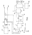
- the apparatus for short-circuiting and disconnecting a line 18 includes a switching unit 10 and a probe unit 12.
- the switching unit 10 is connected to one end of a pair 14,16 of conductors constituting, for example, a telephone line 18, and the probe unit 12 is used at the other end thereof.
- units 10 and 12 are hand-held and battery-operated. Firstly, with particular reference to Fig. 2, we describe switching unit 10.
- the switching unit 10 includes an audio-frequency oscillator 20 which is capable of producing a tone such as a warble tone, preferably in the range 1.5 kHz to 3.0 kHz.
- the oscillator 20 may be shunted by resistor R2, which preferably has a value of one kilohm.
- the switching unit 10 also includes a preamplifier 26, a narrow band filter 28, preferably operating at about 175 Hz, a diode pump rectifier 30, a Schmitt trigger 32, flip-flops 34 and bistable relays A and B (with relay contacts A1 and B1 respectively).
- Other elements are a power source V - as mentioned earlier, this is preferably provided by batteries - a reset switch 36, an on/off switch 38, a sensitive current transformer T1, capacitors C1 (preferably 0.0033 microfarad) and C2 and resistor R1, which is preferably a one megohm resistor.
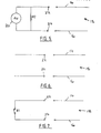
- switching unit 10 When unit 10 is switched on at 38, the oscillator 20 comes up in warble tone mode using the switch-on reset 36 to trigger the flip-flops 34 so that relay A is closed and relay B is open. It can be seen that the warble tone of oscillator 20 is provided to line 18 through contacts 22,24. The first mode is shown in Fig. 5. The output across pair 14,16 is in the vicinity of 0.7V.
- the mode of switching unit 10 changes to a second 'disconnect' mode (Fig. 2) in which case relay A opens and relay B remains open.
- the telephone line 18, looking 'into' the unit 10 is an open circuit with C1 and R1 appearing as shunts.
- the value of C1 is, as stated, preferably small, and from a telephone apparatus viewpoint, simply appears as cable mutual capacitance.
- the value of R1 is chosen high, as stated, preferably 1 megohm, to further make the condition of line 18 look like an open circuit.
- switching unit 10 On receipt of a further signal, again from probe component 12 and again preferably about 175 Hz, a different manner of signal detection is employed by switching unit 10. Current generated by the signal flows through relay contact B1 and current transformer T1. Transformer T1 takes a sample of the 175 Hz signal, which sample is then preamplified by pre-amplifier 26 before being applied to narrow-band filter 28, the Schmitt trigger 32 and the flip-flop array 34. Relay B opens and A closes so that the switching unit 10 returns to the first mode ( Figure 5).
- the transformer T1 may be replaced by a series resistor, typically having a value of 50 milliohm, although the switching unit 10 does not then operate as accurately in the Varley fault location mode.
- the switching unit 10 can switch from one mode to another mode, for example sequentially from first mode to second mode to third mode and back to first mode as required.
- FIG. 3 shows an enhanced version 40 of switching unit 10.
- a third conductor 42 is added to provide a third contact 44, with an additional relay contact B2, to the pair (14,16) under test.
- This third conductor 42 is commonly used in Varley fault location procedure, and, if available, its use provides for greater fault location accuracy.
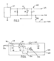
- FIG. 4 shows probe unit 12.
- the probe unit 12 includes a sensitive high-gain receiver 46, which is used to detect the preferred 1.5 kHz - 2.5 kHz warble tone applied to a line 18 by switching unit 10.
- Receiver 46 consists of a high-gain high input impedance preamplifier 48, preferably an audio preamplifier, and a power amplifier 50 which drives an acoustic or other signal device such as a loudspeaker 52 or piezoelectric device.
- a piezoelectric transducer has the benefit of reducing current drain from the battery. Typically, the drain is 5mA with such a transducer, compared to around 40mA with another component.
- the output of the high impedance amplifier 48 is fed via an ideal rectifier, acting as a frequency doubler, to the piezoelectric transducer, the purpose of the frequency doubler being to match the frequency of the identification tone more closely to the resonant frequency of the piezoelectric transducer to obtain the maximum effective audio signal output. More preferably, the output of the frequency doubler is fed via two amplifiers out of phase to the two sides of the piezoelectric transducer, so that the effective output signal from the transducer is effectively doubled.
- Coupling of the receiver 46 to line 18 is capacitive via an insulated metal probe 54.
- the probe 54 By introducing the probe 54 near the cable including the line pair carrying the warble tone a signal is received and that reception is signalled to the technician by device 52. As the probe 54 is moved closer to the pair 14,16 without direct electrical connection the volume of the signal increases, thus allowing identification of the pair.
- the probe unit 12 is capable of being used to detect the null referred to in the introduction to this specification, by moving the probe 54 to find the desired position.
- the probe unit 12 also includes an oscillator 56, preferably a 175 Hz oscillator.
- the oscillator 56 functions when push-button switch 62 is operated, and the output of oscillator 56 is applied to a pair 14,16 by contacts 58,60.
- the units 10,12 of the present embodiment are used by a fault-locating technician as follows.
- the technician couples a switching unit 10 to a desired pair 14,16 via contacts 22,24.
- the switching unit 10 is switched on, and automatically resets via the 'power on' reset switch 36 to the first mode ( Figure 5).
- the technician then travels to a remote end of the line 18 formed of pair 14,16, taking with him a probe unit 12.
- a remote end of the line 18 formed of pair 14,16, taking with him a probe unit 12.
- he arrives at the remote end of the line 18, he identifies the pair 14, 16 using the probe 54 and the technique described hereinbefore.
- the technician Having located the pair, or if the pair is known, the technician connects contacts 58,60 to conductors 14,16. By depressing push-button switch 62 he generates a signal which travels down the line to switching unit 10. The switching unit 10 then switches to the second mode. A further signal burst then switches the switching unit 10 to the third mode, in which state the technician is able to conduct Varley fault location. If the technician were installing a telephone set or other such equipment, he would leave the switching unit 10 in the second mode.
- the technician When the technician has finished his task at the remote end of the line, he disconnects probe unit 12 and departs. Back at the exchange or at the intermediate junction, the technician removes the switching unit 10 from the line 18.
- telephone lines on which the present invention is intended to be used are subject to transient voltages of quite a high order, and consequently protection diodes and transient suppression devices in the form of metal oxide varistors are used where possible to minimize the damaging effects of such transients.
Abstract
Description
- This invention relates to remote disconnection and short-circuiting of a pair of conductors such as those used in telephone or other communications lines.
- One of the most common types of fault in telephone lines is the appearance of resistive paths between legs of a pair to earth, or from one conductor of a pair to another. The resistance of such faults may vary from zero ohms to a megohm or more. The most common technique for locating such faults is to use a Varley bridge type fault locator which requires a short-circuit strap to be placed to one end of the suspect pair.
- Usually the following fault location procedure is followed. A telephone technician places an audio-frequency oscillator on the pair at one end and then proceeds to the other end of the line. The technician then identifies the pair using a very high gain receiver which converts a received signal to an audio output. By searching through the cabling at the remote end of the line, the technician is able to locate the correct pair by looking for the conductors carrying the loudest signal and detecting the null, or area of no signal, in the gap midway between the conductors of the pair. This detection confirms and positively identifies the pair.
- Varley fault location is only able to proceed when the oscillator end of the line is strapped, that is, short-circuited. At present, such an operation requires the technician to travel to the other end of the line, connect a strap to the line, and then travel back to the remote end, where the pair identification has taken place. He then connects the Varley fault locator and proceeds with the location of the fault.
- Clearly, this manner of pair identification for fault location is inefficient and costly. The same disadvantages exist in present methods for the installation of telephones or other communications equipment.
- In such a situation, the telephone pair is connected to a functioning telephone exchange, and thus has typically, 50V between the legs or conductors of the pair. The telephone installer connects an oscillator to the pair at the exchange, or at an intermediate point between the exchange and the subscriber's premises, and then proceeds to the cable joint nearest to the premises to locate the particular pair to which the telephone or other apparatus is to be connected.
- Having located the pair, the installer must connect the telephone and undertake dial and ringback tests. Such tests are only able to be undertaken if the oscillator is firstly removed from the exchange end of - or intermediate point in - the line. This requires the installer to travel to the exchange or intermediate point to disconnect the oscillator from the pair. The installer then returns to the subscriber's premises, connects the telephone or other apparatus and is then able to call the exchange and ask for ringback tests to confirm that the line is operational.
- As with fault location, the present installation procedure involves the technician in travel which is time- consuming and, as a result, costly. In some circumstances, when a technician at the non-exchange end of a line has access to a telephone operating on another line, or to radio communications equipment, he may be able to instruct a second technician at the exchange to perform certain functions at the exchange end of the line in question. However, such access is not usually available, and the use of a second technician would also be costly. Of course, many unmanned exchanges are now used, and if such an exchange were involved, or an intermediate pillar, such a second technician could in any event not be readily utilized.
- It is an object of the invention to provide a method and apparatus for remote short-circuiting and disconnection of a pair of conductors in a line, which does not involve a technician in travel between ends of a line.
- The invention provides apparatus for remote disconnection and short-circuiting of a pair of conductors, characterized by:
a) a switching unit adapted to be connected to one end of said pair of conductors, and
b) a probe unit adapted to be connected to the other end of said pair of conductors,
said probe unit having signal generation means for generating a signal having predetermined characteristics, said signal being capable of being sent by said prove unit along said pair of conductors, said switching unit including detection means for detecting said signal, and switching means for carrying out switching operation on said pair of conductors in response to the receipt of said signal. - The invention also provides a method for disconnecting and short-circuiting a pair of conductors, characterized by the steps of connecting a switching unit to one end of said pair, and connecting a probe unit to the other end of said pair of conductors, causing said probe unit to apply a predetermined signal to said pair, said switching unit being responsive to said signal to switch said conductors between a number of predetermined modes.
- Preferred embodiments of the invention will be described in detail hereinafter, with reference to the accompanying drawings, in which:-
- Figure 1 is a block diagram of a telephone line with the switching unit and the probe unit of one embodiment of the apparatus of this invention in position to be attached thereto;
- Figure 2 is a block diagram of the switching unit of the apparatus of Figure 1;
- Figure 3 is a block diagram of a switching unit enhancement;
- Figure 4 is a block diagram of the probe unit of the apparatus of Figure 1;
- Figure 5 is a line situation diagram with the switching unit in a first mode;
- Figure 6 is a line situation diagram with the switching unit in a second mode; and
- Figure 7 is a line situation diagram with the switching unit in a third mode.
- The apparatus for short-circuiting and disconnecting a
line 18 includes aswitching unit 10 and aprobe unit 12. In use, as is discussed in detail hereinafter, theswitching unit 10 is connected to one end of apair telephone line 18, and theprobe unit 12 is used at the other end thereof. - In this embodiment,
units unit 10. - The
switching unit 10 includes an audio-frequency oscillator 20 which is capable of producing a tone such as a warble tone, preferably in the range 1.5 kHz to 3.0 kHz. Theoscillator 20 may be shunted by resistor R2, which preferably has a value of one kilohm. -
Contacts telephone line 18. Theswitching unit 10 also includes apreamplifier 26, anarrow band filter 28, preferably operating at about 175 Hz, adiode pump rectifier 30, a Schmitt trigger 32, flip-flops 34 and bistable relays A and B (with relay contacts A1 and B1 respectively). Other elements are a power source V - as mentioned earlier, this is preferably provided by batteries - areset switch 36, an on/off switch 38, a sensitive current transformer T1, capacitors C1 (preferably 0.0033 microfarad) and C2 and resistor R1, which is preferably a one megohm resistor. - The operation of switching
unit 10 will now be described. Whenunit 10 is switched on at 38, theoscillator 20 comes up in warble tone mode using the switch-onreset 36 to trigger the flip-flops 34 so that relay A is closed and relay B is open. It can be seen that the warble tone ofoscillator 20 is provided toline 18 throughcontacts pair - When a signal - preferably a 175 Hz signal - appears on line 18 [as a result of
probe unit 12 being activated (to be described hereinafter)] the signal is sampled, and that sample is supplied to narrow-band filter 28 via C1 and R1. Thediode pump rectifier 30 raises the voltage on C2 to operate Schmitttrigger 32, which in turn operates the flip-flops 34 and bistable relays A and B. - Thus the mode of switching
unit 10 changes to a second 'disconnect' mode (Fig. 2) in which case relay A opens and relay B remains open. To all intents and purposes, thetelephone line 18, looking 'into' theunit 10, is an open circuit with C1 and R1 appearing as shunts. The value of C1 is, as stated, preferably small, and from a telephone apparatus viewpoint, simply appears as cable mutual capacitance. The value of R1 is chosen high, as stated, preferably 1 megohm, to further make the condition ofline 18 look like an open circuit. - On receipt of a second signal on
line 18, again fromprobe unit 12 and again is sampled, the sample being supplied to filter 28 via C1 and R1, thence to thediode pump rectifier 30, Schmitt trigger 32 and to flip-flops 34. Relay B closes, and relay A remains open. In this mode,line 18, 'looking into' switchingunit 10, sees a DC short circuit. In this mode (Figure 7)line 18 is in a condition where it may be used for Varley fault location or DC resistance checks. - On receipt of a further signal, again from
probe component 12 and again preferably about 175 Hz, a different manner of signal detection is employed by switchingunit 10. Current generated by the signal flows through relay contact B1 and current transformer T1. Transformer T1 takes a sample of the 175 Hz signal, which sample is then preamplified by pre-amplifier 26 before being applied to narrow-band filter 28, the Schmitt trigger 32 and the flip-flop array 34. Relay B opens and A closes so that the switchingunit 10 returns to the first mode (Figure 5). The transformer T1 may be replaced by a series resistor, typically having a value of 50 milliohm, although theswitching unit 10 does not then operate as accurately in the Varley fault location mode. - It can be seen that by sending repetitive bursts of signal from
probe unit 12, the switchingunit 10 can switch from one mode to another mode, for example sequentially from first mode to second mode to third mode and back to first mode as required. - Figure 3 shows an
enhanced version 40 of switchingunit 10. - In Figure 3, a
third conductor 42 is added to provide athird contact 44, with an additional relay contact B2, to the pair (14,16) under test. Thisthird conductor 42 is commonly used in Varley fault location procedure, and, if available, its use provides for greater fault location accuracy. - Figure 4 shows
probe unit 12. Theprobe unit 12 includes a sensitive high-gain receiver 46, which is used to detect the preferred 1.5 kHz - 2.5 kHz warble tone applied to aline 18 by switchingunit 10. -
Receiver 46 consists of a high-gain highinput impedance preamplifier 48, preferably an audio preamplifier, and apower amplifier 50 which drives an acoustic or other signal device such as aloudspeaker 52 or piezoelectric device. The use of piezoelectric transducer has the benefit of reducing current drain from the battery. Typically, the drain is 5mA with such a transducer, compared to around 40mA with another component. Preferably, the output of thehigh impedance amplifier 48 is fed via an ideal rectifier, acting as a frequency doubler, to the piezoelectric transducer, the purpose of the frequency doubler being to match the frequency of the identification tone more closely to the resonant frequency of the piezoelectric transducer to obtain the maximum effective audio signal output. More preferably, the output of the frequency doubler is fed via two amplifiers out of phase to the two sides of the piezoelectric transducer, so that the effective output signal from the transducer is effectively doubled. - Coupling of the
receiver 46 toline 18 is capacitive via aninsulated metal probe 54. By introducing theprobe 54 near the cable including the line pair carrying the warble tone a signal is received and that reception is signalled to the technician bydevice 52. As theprobe 54 is moved closer to thepair probe unit 12 is capable of being used to detect the null referred to in the introduction to this specification, by moving theprobe 54 to find the desired position. - The
probe unit 12 also includes anoscillator 56, preferably a 175 Hz oscillator. Theoscillator 56 functions when push-button switch 62 is operated, and the output ofoscillator 56 is applied to apair contacts - The
units - Before leaving the exchange or an intermediate junction, the technician couples a switching
unit 10 to a desiredpair contacts unit 10 is switched on, and automatically resets via the 'power on'reset switch 36 to the first mode (Figure 5). - The technician then travels to a remote end of the
line 18 formed ofpair probe unit 12. When he arrives at the remote end of theline 18, he identifies thepair probe 54 and the technique described hereinbefore. - Having located the pair, or if the pair is known, the technician connects
contacts conductors button switch 62 he generates a signal which travels down the line to switchingunit 10. The switchingunit 10 then switches to the second mode. A further signal burst then switches the switchingunit 10 to the third mode, in which state the technician is able to conduct Varley fault location. If the technician were installing a telephone set or other such equipment, he would leave theswitching unit 10 in the second mode. - When the technician has finished his task at the remote end of the line, he disconnects
probe unit 12 and departs. Back at the exchange or at the intermediate junction, the technician removes the switchingunit 10 from theline 18. - It can be seen that the use of the described embodiment of the invention permits a technician to detect faults or otherwise test telephone lines, without having to undertake unnecessary travel. Accordingly, use of the invention will result in the saving of time, with a resultant saving in cost.
- It should be noted that the preferred signalling frequency for the probe until 12 of around 175 kHz has been selected for Australian use for the following reasons:
- a) It is not a harmonic of the commonly used
power frequency 50 Hz and hence there is less likelihood of switchingunit 10 tripping on the receipt of spurious signals from mains-borne interference sources; - b) The signal, having a frequency beneath the nominal telephone bandwidth of 300 Hz to 3500 Hz, would be substantially inaudible to a subscriber;
- c) Some telephone lines use loading coils or other line equalization devices which are in nature generally low pass filters. The 175 Hz signal is therefore not attenuated by such filters.
- It should be noted that in other countries, that other signalling frequencies may be used. 150 Hz could be used in the United States of America.
- It should also be understood that telephone lines on which the present invention is intended to be used are subject to transient voltages of quite a high order, and consequently protection diodes and transient suppression devices in the form of metal oxide varistors are used where possible to minimize the damaging effects of such transients.
Claims (31)
a) a switching unit (10) adapted to be connected to one end of said pair of conductors, and
b) a probe unit (12) adapted to be connected to the other end of said pair of conductors,
said probe unit (12) having signal generation means (56) for generating a signal having predetermined characteristics, said signal being capable of being sent by said probe unit (12) along said pair of conductors (14,16), said switching unit (10) including detection means for detecting said signal, and switching means for carrying out switching operation on said pair of conductors in response to the receipt of said signal.
Priority Applications (1)
| Application Number | Priority Date | Filing Date | Title |
|---|---|---|---|
| AT88303366T ATE96963T1 (en) | 1987-04-14 | 1988-04-14 | REMOTE INTERRUPTION AND SHORT CIRCUIT DEVICE. |
Applications Claiming Priority (2)
| Application Number | Priority Date | Filing Date | Title |
|---|---|---|---|
| AUPI147387 | 1987-04-14 | ||
| AU1473/87 | 1987-04-14 |
Publications (3)
| Publication Number | Publication Date |
|---|---|
| EP0287369A2 true EP0287369A2 (en) | 1988-10-19 |
| EP0287369A3 EP0287369A3 (en) | 1989-09-13 |
| EP0287369B1 EP0287369B1 (en) | 1993-11-03 |
Family
ID=3772120
Family Applications (1)
| Application Number | Title | Priority Date | Filing Date |
|---|---|---|---|
| EP88303366A Expired - Lifetime EP0287369B1 (en) | 1987-04-14 | 1988-04-14 | Remote disconnection and shortcircuiting apparatus |
Country Status (7)
| Country | Link |
|---|---|
| US (1) | US4862491A (en) |
| EP (1) | EP0287369B1 (en) |
| JP (1) | JPS6447135A (en) |
| AT (1) | ATE96963T1 (en) |
| CA (1) | CA1282883C (en) |
| DE (1) | DE3885329T2 (en) |
| ES (1) | ES2050156T3 (en) |
Cited By (4)
| Publication number | Priority date | Publication date | Assignee | Title |
|---|---|---|---|---|
| WO1994013090A1 (en) * | 1992-11-20 | 1994-06-09 | Atlas Telecom International Ltd. | Network termination unit |
| EP0880258A2 (en) * | 1997-05-22 | 1998-11-25 | Teletech Pty Ltd | Remote testing of a communications line |
| EP1001554A2 (en) * | 1998-11-10 | 2000-05-17 | Pittway Corporation | Line shunt and ground fault detection apparatus and method |
| GB2368487A (en) * | 2000-10-25 | 2002-05-01 | Alan Robert Perrett | Remote testing system |
Families Citing this family (11)
| Publication number | Priority date | Publication date | Assignee | Title |
|---|---|---|---|---|
| US4985917A (en) * | 1989-08-17 | 1991-01-15 | Altimier Jr David F | Personal artificial loop (p.a.l.) |
| GB9213992D0 (en) * | 1992-07-01 | 1992-08-12 | Raychem Ltd | Remotely actuated switch and protection circuit |
| GB9218134D0 (en) * | 1992-08-26 | 1992-10-14 | Raychem Sa Nv | Communication channel switching arrangement |
| US5721524A (en) * | 1995-06-07 | 1998-02-24 | Power Parts, Inc. | Stator apparatus for small engine ignition system having improved grounding arrangement |
| GB9602247D0 (en) * | 1996-02-05 | 1996-04-03 | British Telecomm | Telecommunications networks |
| US5771285A (en) * | 1996-02-07 | 1998-06-23 | Lucent Technologies | Circuit and method for detecting telephone line status and telephone instrument embodying the same |
| US5825850A (en) * | 1996-10-02 | 1998-10-20 | Time Warner Entertainment Co. L.P. | Automatic bypass switch for signal conductor |
| SE9800249L (en) * | 1998-01-29 | 1999-07-30 | Telia Ab | Improvements to, or with regard to, telecommunications |
| US6160405A (en) * | 1998-03-30 | 2000-12-12 | Jovial Test Equipment, Inc. | Method and apparatus for remotely changing signal characteristics of a signal generator |
| US6212258B1 (en) * | 1998-11-25 | 2001-04-03 | Westell Technologies, Inc. | Device for remotely testing a twisted pair transmission line |
| US7010096B1 (en) * | 1999-11-24 | 2006-03-07 | Teletech Pty., Ltd. | Remote testing of a communications line |
Citations (6)
| Publication number | Priority date | Publication date | Assignee | Title |
|---|---|---|---|---|
| US3843848A (en) * | 1973-01-12 | 1974-10-22 | Magnetic Controls Co | Telephone looptest system |
| US3912882A (en) * | 1973-12-07 | 1975-10-14 | Tm Systems | Remote loop-back terminating unit for testing telephone |
| EP0091267A2 (en) * | 1982-04-05 | 1983-10-12 | THE GENERAL ELECTRIC COMPANY, p.l.c. | Telecommunication system loop-back unit |
| US4489220A (en) * | 1983-06-08 | 1984-12-18 | International Teldata Ii Corp. | Test set |
| US4550225A (en) * | 1983-10-31 | 1985-10-29 | Keptel, Inc. | AC Signal-activated switching apparatus |
| US4581494A (en) * | 1984-10-09 | 1986-04-08 | James A. Mayberry | Telephone interface-test device |
Family Cites Families (2)
| Publication number | Priority date | Publication date | Assignee | Title |
|---|---|---|---|---|
| US4536703A (en) * | 1982-05-27 | 1985-08-20 | At&T Technologies, Inc. | Method and apparatus for testing cable wire connected to terminals at a remote location |
| US4686696A (en) * | 1985-12-02 | 1987-08-11 | Keptel, Inc. | Transmission line signal sensing circuit employing means for conserving power, especially for use with a telephone disconnect circuit, and associated method |
-
1988
- 1988-04-13 US US07/181,533 patent/US4862491A/en not_active Expired - Lifetime
- 1988-04-14 ES ES88303366T patent/ES2050156T3/en not_active Expired - Lifetime
- 1988-04-14 AT AT88303366T patent/ATE96963T1/en not_active IP Right Cessation
- 1988-04-14 DE DE3885329T patent/DE3885329T2/en not_active Expired - Lifetime
- 1988-04-14 EP EP88303366A patent/EP0287369B1/en not_active Expired - Lifetime
- 1988-04-14 CA CA000564200A patent/CA1282883C/en not_active Expired - Lifetime
- 1988-04-14 JP JP9263688A patent/JPS6447135A/en active Pending
Patent Citations (6)
| Publication number | Priority date | Publication date | Assignee | Title |
|---|---|---|---|---|
| US3843848A (en) * | 1973-01-12 | 1974-10-22 | Magnetic Controls Co | Telephone looptest system |
| US3912882A (en) * | 1973-12-07 | 1975-10-14 | Tm Systems | Remote loop-back terminating unit for testing telephone |
| EP0091267A2 (en) * | 1982-04-05 | 1983-10-12 | THE GENERAL ELECTRIC COMPANY, p.l.c. | Telecommunication system loop-back unit |
| US4489220A (en) * | 1983-06-08 | 1984-12-18 | International Teldata Ii Corp. | Test set |
| US4550225A (en) * | 1983-10-31 | 1985-10-29 | Keptel, Inc. | AC Signal-activated switching apparatus |
| US4581494A (en) * | 1984-10-09 | 1986-04-08 | James A. Mayberry | Telephone interface-test device |
Non-Patent Citations (1)
| Title |
|---|
| D.G. FINK et al.: "Electronics engineers' handbook", 2nd edition, 1982, pages 12.34-12.35, Mcgraw-Hill Book Co., New York, US * |
Cited By (9)
| Publication number | Priority date | Publication date | Assignee | Title |
|---|---|---|---|---|
| WO1994013090A1 (en) * | 1992-11-20 | 1994-06-09 | Atlas Telecom International Ltd. | Network termination unit |
| US5550894A (en) * | 1992-11-20 | 1996-08-27 | Atlas Telecom International Ltd. | Device for sequentially altering a communication line for remote diagnostic checks |
| US5661776A (en) * | 1992-11-20 | 1997-08-26 | Atlas Telecom International Ltd. | Method and apparatus for performing impedance measurements on a communication line |
| EP0880258A2 (en) * | 1997-05-22 | 1998-11-25 | Teletech Pty Ltd | Remote testing of a communications line |
| EP0880258A3 (en) * | 1997-05-22 | 2002-07-17 | Teletech Pty Ltd | Remote testing of a communications line |
| EP1001554A2 (en) * | 1998-11-10 | 2000-05-17 | Pittway Corporation | Line shunt and ground fault detection apparatus and method |
| EP1001554A3 (en) * | 1998-11-10 | 2000-06-14 | Pittway Corporation | Line shunt and ground fault detection apparatus and method |
| US6292541B1 (en) | 1998-11-10 | 2001-09-18 | Pittway Corporation | Line shunt and ground fault apparatus method |
| GB2368487A (en) * | 2000-10-25 | 2002-05-01 | Alan Robert Perrett | Remote testing system |
Also Published As
| Publication number | Publication date |
|---|---|
| US4862491A (en) | 1989-08-29 |
| ES2050156T3 (en) | 1994-05-16 |
| CA1282883C (en) | 1991-04-09 |
| ATE96963T1 (en) | 1993-11-15 |
| EP0287369B1 (en) | 1993-11-03 |
| JPS6447135A (en) | 1989-02-21 |
| EP0287369A3 (en) | 1989-09-13 |
| DE3885329T2 (en) | 1994-05-26 |
| DE3885329D1 (en) | 1993-12-09 |
Similar Documents
| Publication | Publication Date | Title |
|---|---|---|
| US3882287A (en) | Method and apparatus for detecting faults and locating conductors in multi-conductor cables | |
| US4862491A (en) | Remote disconnection and short-circuiting apparatus and method | |
| US3843848A (en) | Telephone looptest system | |
| US6763108B1 (en) | Apparatus and method for line pair testing and fault diagnostics | |
| US6181775B1 (en) | Dual test mode network interface unit for remote testing of transmission line and customer equipment | |
| US3636280A (en) | Telephone line testing from remote locations | |
| US3912882A (en) | Remote loop-back terminating unit for testing telephone | |
| US6212258B1 (en) | Device for remotely testing a twisted pair transmission line | |
| US4169220A (en) | Telephone instrument connection block with remotely actuated line test | |
| US4415779A (en) | Methods of and apparatus for testing telephone subscriber loop to locate a fault relative to a reference point | |
| US5115462A (en) | Remotely controlled apparatus for conditioning telephone line exclusive of metallic DC bypass pair | |
| US3766336A (en) | Circuit isolating switching arrangement | |
| JPS5882170A (en) | Test system detecting short circuit and release of two conductor type circuit | |
| US3919487A (en) | Telephone instrument disconnect circuit | |
| US4413163A (en) | Portable line tester for telecommunication system | |
| AU604878B2 (en) | Telephone line remote looping method and apparatus | |
| US4440985A (en) | Apparatus for determining the location of faults in a transmission line | |
| US4336422A (en) | Toll restrictor | |
| JPH0422595Y2 (en) | ||
| US3749857A (en) | Cable testing device for long-distance cables, particularly for occupied cables | |
| JP3657064B2 (en) | High voltage insulation constant monitoring device | |
| US4081608A (en) | Arrangement for remote control apparatus | |
| EP1151596A1 (en) | The testing of telephone lines | |
| EP1107552A2 (en) | Apparatus and method for testing subscriber loop interface circuits | |
| EP0530153A2 (en) | Intermediate telephone line sectioning device |
Legal Events
| Date | Code | Title | Description |
|---|---|---|---|
| PUAI | Public reference made under article 153(3) epc to a published international application that has entered the european phase |
Free format text: ORIGINAL CODE: 0009012 |
|
| AK | Designated contracting states |
Kind code of ref document: A2 Designated state(s): AT BE CH DE ES FR GB GR IT LI LU NL SE |
|
| PUAL | Search report despatched |
Free format text: ORIGINAL CODE: 0009013 |
|
| AK | Designated contracting states |
Kind code of ref document: A3 Designated state(s): AT BE CH DE ES FR GB GR IT LI LU NL SE |
|
| 17P | Request for examination filed |
Effective date: 19900307 |
|
| 17Q | First examination report despatched |
Effective date: 19920312 |
|
| GRAA | (expected) grant |
Free format text: ORIGINAL CODE: 0009210 |
|
| AK | Designated contracting states |
Kind code of ref document: B1 Designated state(s): AT BE CH DE ES FR GB GR IT LI LU NL SE |
|
| PG25 | Lapsed in a contracting state [announced via postgrant information from national office to epo] |
Ref country code: LI Effective date: 19931103 Ref country code: CH Effective date: 19931103 |
|
| REF | Corresponds to: |
Ref document number: 96963 Country of ref document: AT Date of ref document: 19931115 Kind code of ref document: T |
|
| REF | Corresponds to: |
Ref document number: 3885329 Country of ref document: DE Date of ref document: 19931209 |
|
| ITF | It: translation for a ep patent filed |
Owner name: FUMERO BREVETTI S.N.C. |
|
| REG | Reference to a national code |
Ref country code: CH Ref legal event code: PL |
|
| ET | Fr: translation filed | ||
| REG | Reference to a national code |
Ref country code: GR Ref legal event code: FG4A Free format text: 3010662 |
|
| REG | Reference to a national code |
Ref country code: ES Ref legal event code: FG2A Ref document number: 2050156 Country of ref document: ES Kind code of ref document: T3 |
|
| EPTA | Lu: last paid annual fee | ||
| PLBE | No opposition filed within time limit |
Free format text: ORIGINAL CODE: 0009261 |
|
| STAA | Information on the status of an ep patent application or granted ep patent |
Free format text: STATUS: NO OPPOSITION FILED WITHIN TIME LIMIT |
|
| 26N | No opposition filed | ||
| EAL | Se: european patent in force in sweden |
Ref document number: 88303366.4 |
|
| REG | Reference to a national code |
Ref country code: GB Ref legal event code: IF02 |
|
| PGFP | Annual fee paid to national office [announced via postgrant information from national office to epo] |
Ref country code: SE Payment date: 20070412 Year of fee payment: 20 Ref country code: LU Payment date: 20070412 Year of fee payment: 20 |
|
| PGFP | Annual fee paid to national office [announced via postgrant information from national office to epo] |
Ref country code: AT Payment date: 20070413 Year of fee payment: 20 Ref country code: NL Payment date: 20070413 Year of fee payment: 20 |
|
| PGFP | Annual fee paid to national office [announced via postgrant information from national office to epo] |
Ref country code: DE Payment date: 20070423 Year of fee payment: 20 |
|
| PGFP | Annual fee paid to national office [announced via postgrant information from national office to epo] |
Ref country code: ES Payment date: 20070427 Year of fee payment: 20 |
|
| PGFP | Annual fee paid to national office [announced via postgrant information from national office to epo] |
Ref country code: BE Payment date: 20070502 Year of fee payment: 20 |
|
| PGFP | Annual fee paid to national office [announced via postgrant information from national office to epo] |
Ref country code: GB Payment date: 20070426 Year of fee payment: 20 |
|
| PGFP | Annual fee paid to national office [announced via postgrant information from national office to epo] |
Ref country code: IT Payment date: 20070628 Year of fee payment: 20 |
|
| BE20 | Be: patent expired |
Owner name: *TELETECH PTY LTD Effective date: 20080414 |
|
| PGFP | Annual fee paid to national office [announced via postgrant information from national office to epo] |
Ref country code: FR Payment date: 20070416 Year of fee payment: 20 |
|
| REG | Reference to a national code |
Ref country code: GB Ref legal event code: PE20 Expiry date: 20080413 |
|
| PG25 | Lapsed in a contracting state [announced via postgrant information from national office to epo] |
Ref country code: NL Free format text: LAPSE BECAUSE OF EXPIRATION OF PROTECTION Effective date: 20080414 |
|
| PGFP | Annual fee paid to national office [announced via postgrant information from national office to epo] |
Ref country code: GR Payment date: 20070420 Year of fee payment: 20 |
|
| NLV7 | Nl: ceased due to reaching the maximum lifetime of a patent |
Effective date: 20080414 |
|
| EUG | Se: european patent has lapsed | ||
| REG | Reference to a national code |
Ref country code: ES Ref legal event code: FD2A Effective date: 20080415 |
|
| PG25 | Lapsed in a contracting state [announced via postgrant information from national office to epo] |
Ref country code: ES Free format text: LAPSE BECAUSE OF EXPIRATION OF PROTECTION Effective date: 20080415 |
|
| PG25 | Lapsed in a contracting state [announced via postgrant information from national office to epo] |
Ref country code: GB Free format text: LAPSE BECAUSE OF EXPIRATION OF PROTECTION Effective date: 20080413 |