EP0288239A2 - Perforating gun firing tool - Google Patents
Perforating gun firing tool Download PDFInfo
- Publication number
- EP0288239A2 EP0288239A2 EP88303501A EP88303501A EP0288239A2 EP 0288239 A2 EP0288239 A2 EP 0288239A2 EP 88303501 A EP88303501 A EP 88303501A EP 88303501 A EP88303501 A EP 88303501A EP 0288239 A2 EP0288239 A2 EP 0288239A2
- Authority
- EP
- European Patent Office
- Prior art keywords
- valve
- annulus
- pressure
- flow
- pipe string
- Prior art date
- Legal status (The legal status is an assumption and is not a legal conclusion. Google has not performed a legal analysis and makes no representation as to the accuracy of the status listed.)
- Ceased
Links
Images


Classifications
-
- E—FIXED CONSTRUCTIONS
- E21—EARTH DRILLING; MINING
- E21B—EARTH DRILLING, e.g. DEEP DRILLING; OBTAINING OIL, GAS, WATER, SOLUBLE OR MELTABLE MATERIALS OR A SLURRY OF MINERALS FROM WELLS
- E21B23/00—Apparatus for displacing, setting, locking, releasing, or removing tools, packers or the like in the boreholes or wells
- E21B23/004—Indexing systems for guiding relative movement between telescoping parts of downhole tools
- E21B23/006—"J-slot" systems, i.e. lug and slot indexing mechanisms
-
- E—FIXED CONSTRUCTIONS
- E21—EARTH DRILLING; MINING
- E21B—EARTH DRILLING, e.g. DEEP DRILLING; OBTAINING OIL, GAS, WATER, SOLUBLE OR MELTABLE MATERIALS OR A SLURRY OF MINERALS FROM WELLS
- E21B34/00—Valve arrangements for boreholes or wells
- E21B34/06—Valve arrangements for boreholes or wells in wells
- E21B34/10—Valve arrangements for boreholes or wells in wells operated by control fluid supplied from outside the borehole
-
- E—FIXED CONSTRUCTIONS
- E21—EARTH DRILLING; MINING
- E21B—EARTH DRILLING, e.g. DEEP DRILLING; OBTAINING OIL, GAS, WATER, SOLUBLE OR MELTABLE MATERIALS OR A SLURRY OF MINERALS FROM WELLS
- E21B43/00—Methods or apparatus for obtaining oil, gas, water, soluble or meltable materials or a slurry of minerals from wells
- E21B43/11—Perforators; Permeators
- E21B43/116—Gun or shaped-charge perforators
- E21B43/1185—Ignition systems
- E21B43/11852—Ignition systems hydraulically actuated
-
- E—FIXED CONSTRUCTIONS
- E21—EARTH DRILLING; MINING
- E21B—EARTH DRILLING, e.g. DEEP DRILLING; OBTAINING OIL, GAS, WATER, SOLUBLE OR MELTABLE MATERIALS OR A SLURRY OF MINERALS FROM WELLS
- E21B49/00—Testing the nature of borehole walls; Formation testing; Methods or apparatus for obtaining samples of soil or well fluids, specially adapted to earth drilling or wells
- E21B49/001—Testing the nature of borehole walls; Formation testing; Methods or apparatus for obtaining samples of soil or well fluids, specially adapted to earth drilling or wells specially adapted for underwater installations
-
- E—FIXED CONSTRUCTIONS
- E21—EARTH DRILLING; MINING
- E21B—EARTH DRILLING, e.g. DEEP DRILLING; OBTAINING OIL, GAS, WATER, SOLUBLE OR MELTABLE MATERIALS OR A SLURRY OF MINERALS FROM WELLS
- E21B2200/00—Special features related to earth drilling for obtaining oil, gas or water
- E21B2200/04—Ball valves
Definitions
- the invention relates to apparatus for completing a cased borehole and, more particularly, to a tool for use in activating an explosive charge downhole in a wellbore.
- One prior art means of firing the gun is to use a firing head which is actuated by a metal bar dropped down the tubing string. While this means has the advantage that the gun does not go off prematurely, it obviously cannot be used in wellbores that deviate significantly from the vertical. Another disadvantage is that the firing head may become fouled by heavy drilling mud or debris before the bar is dropped, preventing actuation of the gun.
- One method is to apply pressure through the tubing string to a pressure responsive firing device, an example of which is disclosed in U.S. Patent No. 4,544,034 to George.
- the firing device is in fluid communication with the surface, either using a liquid or nitrogen, and pressure applied at the surface is communicated through the fluid column to the firing device. While this is a useful system in many applications, it is not suitable in those circumstances where a full column of fluid in the tubing string cannot be used. It may also be unsuitable when the formation pressure is low, and it is not possible to bleed off sufficient fluid between actuation and firing to produce a condition of underbalance at the time of perforation.
- annulus pressure is used to operate a pressure activated firing device for a perforating gun without obstructing the tube bore. It is particularly suited to situations where a full column of fluid in the tube cannot be used, or where it is necessary or desirable to perforate the casing underbalanced.
- the apparatus comprises a pipe string with a packer, and a perforating gun at the end of the string.
- the string is fitted with a flow valve located above the packer which prevents fluid flow through the bore of the pipe when it is closed.
- Below the flow valve and above the packer the wall of the pipe is provided with one or more valves giving access from the annulus to the tube bore when open. Means are provided which operate the valves, opening one while closing the other.
- the or each access annulus valve comprises a circulation port in the wall of the pipe string and a valve sleeve which slides longitudinally against the inside wall of the pipe string and which contains circulation apertures alignable with the circulation ports.
- valve sleeve is moved by a tubular mandrel which slides up and down against the interior wall of the tool.
- This mandrel is also adapted to open and close the flow valve so that the flow valve opens when the circulation valve closes and vice versa.
- the mandrel moves in response to changes in the upper annulus pressure.
- Movement of the mandrel is effected by an operating fluid housed between the tool wall and the mandrel which is in communication with the pressure in the upper annulus and a double acting piston which moves in response to pressure differentials across it caused by pressure changes in the operating fluid.
- the piston moves the mandrel, preferably through a ball and slot ratchet mechanism which controls the longitudinal movement of the mandrel.
- the double-acting pistons have means for dumping the fluid when they reach the end of their stroke, thus equalizing the pressure on both sides of the piston and preventing further movement.
- the access annulus valve is a chemical injection type valve which opens when there is sufficient pressure in the upper annulus and closes when that pressure is released. This is preferably used in conjunction with a flow valve operated by annulus pressure.
- the method of using the apparatus of the invention to complete a well comprises suspending the apparatus in the well with the perforating gun in the location to be perforated, and setting the packer to form an upper and lower annulus.
- the flow valve is closed and the annulus access valves are opened.
- the pressure in the upper annulus is then increased to the pressure required to activate the pressure-activated firing head of the perforating gun.
- the annulus access valves are closed and the flow valve is opened, permitting fluids to flow from the formation through the well perforation up the pipe string to the surface. If a time delay firing head is used, pressure can be bled off the tool through the open flow valve after the firing head is activated and before the gun detonates to permit perforation at underbalance.
- the present invention provides a safe, pressure activated means of detonating a perforating gun in response to a predetermined pressure applied from the surface, while maintaining an unobstructed flow bore throughout the pipe string.
- the tool of the present invention can be readily cycled to test packer seal integrity, to activate the firing head and to allow firing the perforating gun underbalanced.
- FIG. 1 the present invention is shown schematically incorporated in a perforating gun firing string deployed in an offshore oil or gas well
- Platform 2 is shown positioned over a submerged oil or gas well bore 4 located in sea floor 6, well bore 4 penetrating potential producing formation 8.
- Well bore 4 is shown to be lined with steel casing 10, which is cemented into place.
- a subsea conduit 12 extends from the deck 14 of platform 2 into a subsea wellhead 16, which includes a blowout preventer 18 therein.
- Platform 2 carries a derrick 20 thereon, as well as a hoisting apparatus 22, and a pump 24 which communicates with the well bore 4 via control conduit 26, which extends below blowout preventer 18.
- Perforating gun firing string 30 is shown disposed in well bore 4, with blowout preventer 18 closed thereabout.
- Perforating gun firing string 30 includes upper drill pipe string 32 which extends downward from platform 2 to wellhead 16, below which extends intermediate pipe string 36.
- Slip joint 38 may be included in string 36 to compensate for vertical motion imparted to platform 2 by wave action; slip joint 38 may be similar to that disclosed in U.S. Patent No. 3,354,950 to Hyde.
- Below slip joint 38 intermediate string 36 extends downwardly to perforating gun firing tool 50 of present invention.
- Below firing tool 50 is lower pipe string 40, extending to tubing seal assembly 42, which stabs into packer 44. When set, packer 44 isolates well bore annulus 46 from lower well bore annulus 48.
- Packer 44 may be any suitable packer well known in the art, such as, for example, a Baker Oil Tool Model D packer, an Otis Engineering Corporation type W packer, or Halliburton Services CHAMP®, RTTS or EZ DRILL® SV packers.
- perforating gun 52 which may be any type of tubing pressure actuated perforating gun known in the art. Particularly preferred is the perforating gun with time delay firing mechanism disclosed in U.S. Patent No. 4,614,156 to Colle et al.
- Perforating gun 52 is actuated by a pressure responsive firing head 54 located in the pipe string below packer 44.
- tool 50 is shown in section, commencing at the bottom of the tool with lower adapter 100 having threads 102 therein at its lower end, whereby tool 50 is secured to lower pipe string 40.
- Lower adapter 100 is secured to nitrogen valve housing 104 at threaded connection 106, housing 104 containing a valve assembly (not shown), such as is well known in the art, in lateral bore 108 in the wall thereof, from which extends up longitudinal nitrogen charging channel 110.
- Valve housing 104 is secured by threaded connection 112 at its outer upper end to tubular pressure case 114, and by threaded connection 116 at its inner upper end to gas chamber mandrel 118, case 114 and mandrel 118 defining pressurized gas chamber 120 and lower oil chamber 122, the two being separated by floating annular piston 124.
- the lower end of oil channel coupling 126 extends between case 114 and gas chamber mandrel 118, and is secured to the upper end of case 114 at threaded connection 128.
- a plurality of longitudinal oil channels 130 (one shown) extend from the lower end of coupling 126 to the upper end thereof.
- Radially drilled oil fill ports 132 extend from the exterior of tool 50, intersecting channels 130 and are closed with plugs 134.
- Annular shoulder 136 extends radially inward from inner wall 138 of coupling 126.
- the upper end of coupling 126, including annular overshot 127, is secured at threaded connection 140 to the lower end of ratchet case 142, through which oil fill ports 144 extend at annular shoulder 146, being closed by plugs 148.
- At the upper end of ratchet case 142 are additional oil fill ports 150 closed by plugs 152 and open pressure ports 154.
- Ratchet slot mandrel 156 extends downward within the upper end of oil channel coupling 126.
- Annular ratchet chamber 158 is defined between mandrel 156 and case 142.
- the lower exterior 160 of mandrel 156 is of substantially uniform diameter, while the upper exterior 162 is of greater diameter so as to provide sufficient wall thickness for ratchet slot 164.
- Fig. 4 shows the pattern of ratchet slot 164 extending 180° around the exterior of ratchet slot mandrel 156. The same pattern is repeated on the second 180° of the exterior of mandrel 156, making a continuous slot 164 around mandrel 156.
- Ball sleeve assembly 166 surrounds ratchet slot mandrel 156, and comprises lower sleeve 168 including radially outwardly extending annular shoulder 170 having annular piston seat 172 thereon. Above shoulder 170, ratchet piston support surface 173 extends to the upper end of lower sleeve 168, which is overshot by the lower end of upper sleeve 174 having annular piston seat 176 thereon, and to which is secured at threaded connection 178. Ball sleeve 180 is disposed at the top of upper sleeve 174, and is secured thereto at swivel bearing race 182 by a plurality of bearings 184.
- Two ratchet balls 186 each extend into a ball seat 188 on diametrically opposite sides of ball sleeve 180 and into a ratchet slot 164 of semicircular cross-section. Due to this structure, when balls 186 follow the path of slots 164, ball sleeve 180 rotates with respect to upper sleeve 174, the remainder of ball sleeve assembly 166 does not rotate, and only longitudinal movement is transmitted to ratchet mandrel 156 by balls 186.
- Lower annular ratchet piston 190 and upper annular ratchet piston 192 ride on piston support surface 173 on lower sleeve 168, coil spring 194 being disposed therebetween.
- Lower ratchet piston 190 carries radial sealing surface 196 on its lower end, while upper ratchet piston 192 carries radial sealing surface 198 on its upper end.
- ratchet slot mandrel 156 is secured at threaded connection 202 to extension mandrel 204 having relief ports 208 extending therethrough.
- Annular upper oil chamber 210 is defined by ratchet case 142 and extension mandrel 204.
- Annular floating piston 212 slidingly seals the bottom of upper oil chamber 210 and divides it from well fluid chamber 214 into which pressure ports 154 opens.
- the upper end of ratchet case 142 is secured at threaded connection 218, to extension case 216, which surrounds extension mandrel 204.
- Circulation housing 220 is threaded at 222 to extension case 216, and possesses a plurality of circumferentially spaced radially extending circulation ports 224 extending through the wall thereof.
- a plurality of apertures 226 are provided to prevent fluid lock when circulation ports 224 are in communication with the interior bore of tube 50.
- Circulation port sleeve 228 is threaded to extension mandrel 204 at 230.
- Valve apertures 232 extend through the wall of circulation valve sleeve 238, and are isolated from circulation ports 224 by annular seal 234, which is disposed in seal recess 236 formed by the junction of circulation valve sleeve 228 with displacement valve sleeve 238, the two being threaded together at 240.
- Above valve apertures 232 is annular seal 242 disposed in a groove on external surface of displacement valve sleeve 238.
- operating mandrel 260 extends upwardly to exterior annular recess 267, which separates annular shoulder 268 from the main body of mandrel 260.
- Collet sleeve 270 having collet fingers 272 extending downward therefrom, engages operating mandrel 260 through the accommodation of radially inwardly extending protuberances 274 by annular recess 267.
- protuberances 274 and the lower portions of fingers 272 are confined between the exterior of mandrel 260 and the interior of circulation displacement housing 220.
- coupling 276 comprising flanges 278 and 280, with exterior annular recess 282 therebetween, grips coupling 284, comprising inwardly extending flanges 286 and 288 with interior recess 290 therebetween, on each of two ball operating arms 292.
- Couplings 276 and 284 are maintained in engagement by their location in annular recess 296 between ball case 294, which is threaded at 295 to circulation displacement housing 220, and ball housing 298.
- Ball housing 298 is of substantially tubular configuration, having a lower smaller diameter portion 300 and an upper, larger diameter portion 302 which has two windows 304 cut through the wall thereof to accommodate the inward protrusion of lugs 306 from each of the two ball operating arms 292.
- Windows 304 extend from shoulder 311 upward to shoulder 314 adjacent threaded connection 316 with ball support 340.
- two longitudinal channels (location shown by arrow 308) of arcuate cross-section and circumferentially aligned with windows 304, extend from shoulder 310 upward to shoulder 311.
- Ball operating arms 292 which are of substantially the same arcuate cross-section as channels 308 and lower portion 302 of ball housing 298, lie in channels 308 and across windows 304, and are maintained in place by the interior wall 318 of ball case 294 and the exterior of ball support 340.
- the interior of ball housing 298 possesses lower annular seat recess 320, within which annular ball seat 322 is disposed, being biased upwardly against ball 330 by ring spring 324.
- Surface 326 of lower seat 322 comprises a metal sealing surface, which provides a sliding seal with the exterior 332 of valve ball 300.
- Valve ball 330 includes a diametrical bore 334 therethrough, of substantially the same diameter as bore 328 of ball housing 298.
- Two lug recesses 336 extend from the exterior 332 of valve ball 330 to bore 334.
- the upper end 342 of ball support 340 extends into ball housing 298, and carries upper ball seat recess 344 in which annular upper ball seat 346 is disposed.
- Upper ball seat 346 possesses arcuate metal sealing surface 348 which slidingly seals against the exterior 332 of valve ball 330.
- Exterior annular shoulder 350 on ball support 340 is contacted by the lower ends 352 of splines 354 on the exterior of ball case 294, whereby the assembly of ball housing 294, ball operating arms 292, valve ball 330, ball seats 322 and 346 and spring 324 are maintained in position inside of ball case 294.
- Splines 354 engage splines 356 on the exterior of ball support 340, and thus rotation of the ball support 340 and ball housing 298 within ball case 298 is prevented.
- Upper adapter 360 protrudes at its lower end 362 between ball case 298 and ball support 340, sealing therebetween, when made up with ball support 340 at threaded connection 364.
- the upper end of upper adapter 360 carries on its interior threads 366 for making up with portions of drill string above tool 50.
- valve ball 330 When valve ball 330 is in its open position, as shown in Fig. 2G, a "full open" bore 370 extends throughout tool 50, providing an unimpeded path for formation fluids and/or for perforating guns, wireline instrumentation, etc.
- piston 190 reaches overshot 127 which prevents further downward movement. Further fluid pressure acts on shoulder 170 of lower sleeve 168, spreading piston seat 172 from seating surface 196, breaking the seal and dumping oil past lower sleeve 168 which equalizes the pressures on both sides of piston 190, stopping further movement of ball sleeve assembly 166.
- pressure is increased in annulus 46 by pump 24 via control conduit 26.
- This increase in pressure is transmitted through pressure ports 154 into well fluid chamber 214, where it acts upon floating piston 212, moving it downward.
- the pressure is transmitted through the fluid in upper oil chamber 210 to ratchet chamber 158, where the pressurized oil presses on lower ratchet piston 190.
- the oil is prevented from bypassing piston 190 by the metal to metal seal of sealing surface 196 on piston seat 172. Piston 190 therefore pushes against shoulder 170 on lower sleeve 168, which in turn pulls upper sleeve 174, ball sleeve 180 and balls 186 downward in slots 164 to position "d".
- the string is then run further into the well until the perforating gun reaches the position adjacent to the formation to be perforated, and the packer is set.
- the packer is then tested by again pressuring the upper annulus 46.
- This increase of pressure moves balls 186 to positions "f" in slots 164 shown in Fig. 4, by the same means as described above.
- the pressure is then decreased, moving balls 186 to position "g" where they shoulder against slots 164 and effect upwards movement of ratchet mandrel 156, extension mandrel 204, circulation valve sleeve 238, operating mandrel 260 and collet sleeve 270.
- This has the effect of closing circulation ports 224 by moving apertures 232 out of alignment and opening flow valve 330 by means of arms 292.
- Pressure is then increased in the annulus until a sufficient pressure to actuate the firing head 54 is reached. This increase in pressure moves balls 186 to position "m” shown on Fig. 5. Once the firing head 54 has been actuated, the pressure in the annulus is decreased, moving the balls 186 to position "n" where the flow valve 330 is opened and the circulation valves 232 are closed. The pressure in the tubing string can then be bled off before the perforating gun fires, if a time delay firing system is used, creating a suitable underbalance at the time of perforation.
- the tool 50 may be run down the well in the position shown in Figs. 3A and B, with ball valve 330 closed and circulation valves 232 open. This would be done if no cushion was desired, or if a cushion is to be supplied by fluids injected from the surface after the perforating gun 52 is in position. In this mode the balls 186 would start at position "d" on Fig. 5, and would thereafter follow the same cycle.
- FIG. 5 An alternative embodiment of the present invention is shown in Fig. 5.
- the circulation valve with slideable sleeve of the above described embodiment is replaced by injection valve 400.
- the valve 400 is lodged in bore 402 which connects the exterior 404 of valve housing 406 with interior 408.
- the head 410 of valve 400 is maintained in sealing contact with the sloping shoulders 412 of bore 402 by coil spring 414.
- the spring 414 is selected so that it will begin to compress at a predetermined pressure dependent upon the particular circumstances in which the invention is to be used, which is readily calcuable by those of ordinary skill in the art. When this pressure is present in the annulus fluid, the head 410 is forced out of sealing contact with shoulders 412 and fluid flows past valve 400 through bore 402 into the interior 408.
- spring 414 forces head 410 back into sealing contact with shoulders 412, closing valve 400 and preventing flow in either direction through bore 402.
- Valve housing 406 is connected at its upper end through upper adapter 416 to the housing of a conventional tubing valve which prevents flow through the pipe string when closed.
- a conventional tubing valve which prevents flow through the pipe string when closed.
- an annulus pressure actuated tubing valve is used, arranged so that it closes at the same annulus pressure which opens injection valve 400 and opens when the pressure has dropped to the point at which injection valve 400 closes.
- Particularly preferred is the Halliburton APR ®-N Tester Valve.
- Valve housing 408 is connected at its lower end through lower adaptor 418 to the lower string with the packer 44 and the pressure responsive firing head 54 and perforating gun 52.
- the operation of this embodiment follows the same cycles as the operation of a preferred embodiment described above.
- the pipe string is run into the well with the tubing valve open and the injection valve shut.
- the tubing is shut in by increasing the annulus pressure to close the tubing valve and open the injection valve.
- the pipe string then is run further in until the perforating gun is in position.
- the packer is set, and the annulus pressure released to open the tubing valve and close the injection valve.
- the annulus pressure is increased to test the packer, but is left below the predetermined pressure so that the valves do not change position.
- the annulus pressure is increased to open the injection valve and close the tubing valve, and then increased to a sufficient pressure to actuate the firing head. Once the firing head is actuated, the annulus pressure is released, closing the injection valve and opening the tubing valve so that pressure in the tubing can be bled off.
Landscapes
- Geology (AREA)
- Life Sciences & Earth Sciences (AREA)
- Engineering & Computer Science (AREA)
- Mining & Mineral Resources (AREA)
- Environmental & Geological Engineering (AREA)
- Fluid Mechanics (AREA)
- Physics & Mathematics (AREA)
- General Life Sciences & Earth Sciences (AREA)
- Geochemistry & Mineralogy (AREA)
- Soil Working Implements (AREA)
- Earth Drilling (AREA)
- Consolidation Of Soil By Introduction Of Solidifying Substances Into Soil (AREA)
- Check Valves (AREA)
Abstract
Description
- The invention relates to apparatus for completing a cased borehole and, more particularly, to a tool for use in activating an explosive charge downhole in a wellbore.
- After a wellbore has been cased and the casing cemented into place, it is common practice to form perforations in the casing and cement in the region of hydrocarbon bearing formation using a perforating gun. This is lowered into position, and then fired.
- One prior art means of firing the gun is to use a firing head which is actuated by a metal bar dropped down the tubing string. While this means has the advantage that the gun does not go off prematurely, it obviously cannot be used in wellbores that deviate significantly from the vertical. Another disadvantage is that the firing head may become fouled by heavy drilling mud or debris before the bar is dropped, preventing actuation of the gun.
- Various means have been proposed to use pressure applied at the wellhead to actuate the perforating gun. Because of the potentially serious consequences of premature detonation, the actuating mechanism must be able to prevent accidental detonation by pressure changes while the gun is being put into position.
- One method is to apply pressure through the tubing string to a pressure responsive firing device, an example of which is disclosed in U.S. Patent No. 4,544,034 to George. The firing device is in fluid communication with the surface, either using a liquid or nitrogen, and pressure applied at the surface is communicated through the fluid column to the firing device. While this is a useful system in many applications, it is not suitable in those circumstances where a full column of fluid in the tubing string cannot be used. It may also be unsuitable when the formation pressure is low, and it is not possible to bleed off sufficient fluid between actuation and firing to produce a condition of underbalance at the time of perforation.
- A method of using the annulus pressure to activate the firing mechanism is disclosed in U.S. Patents Nos. 4,484,632 to Vann and 4,564,076 to Vann et al. When the perforating gun is in position a packer is set above the formation. An increase in the annulus pressure above the packer is communicated to a lever mechanism inside the tube. At a predetermined pressure, shear pins break and the lever operates the firing mechanism of the perforating gun. This method permits shooting underbalanced, but has the disadvantage that the lever mechanism obstructs part of the tube bore, so that the full bore tools cannot be passed down the tube beyond the firing device.
- We have now devised an apparatus wherein annulus pressure is used to operate a pressure activated firing device for a perforating gun without obstructing the tube bore. It is particularly suited to situations where a full column of fluid in the tube cannot be used, or where it is necessary or desirable to perforate the casing underbalanced.
- The apparatus comprises a pipe string with a packer, and a perforating gun at the end of the string. The string is fitted with a flow valve located above the packer which prevents fluid flow through the bore of the pipe when it is closed. Below the flow valve and above the packer the wall of the pipe is provided with one or more valves giving access from the annulus to the tube bore when open. Means are provided which operate the valves, opening one while closing the other.
- In a preferred embodiment, the or each access annulus valve comprises a circulation port in the wall of the pipe string and a valve sleeve which slides longitudinally against the inside wall of the pipe string and which contains circulation apertures alignable with the circulation ports.
- Preferably, the valve sleeve is moved by a tubular mandrel which slides up and down against the interior wall of the tool. This mandrel is also adapted to open and close the flow valve so that the flow valve opens when the circulation valve closes and vice versa. The mandrel moves in response to changes in the upper annulus pressure.
- Movement of the mandrel is effected by an operating fluid housed between the tool wall and the mandrel which is in communication with the pressure in the upper annulus and a double acting piston which moves in response to pressure differentials across it caused by pressure changes in the operating fluid. The piston moves the mandrel, preferably through a ball and slot ratchet mechanism which controls the longitudinal movement of the mandrel.
- In the preferred embodiment, the double-acting pistons have means for dumping the fluid when they reach the end of their stroke, thus equalizing the pressure on both sides of the piston and preventing further movement.
- In an alternative embodiment, the access annulus valve is a chemical injection type valve which opens when there is sufficient pressure in the upper annulus and closes when that pressure is released. This is preferably used in conjunction with a flow valve operated by annulus pressure.
- The method of using the apparatus of the invention to complete a well comprises suspending the apparatus in the well with the perforating gun in the location to be perforated, and setting the packer to form an upper and lower annulus. The flow valve is closed and the annulus access valves are opened. The pressure in the upper annulus is then increased to the pressure required to activate the pressure-activated firing head of the perforating gun. Once the firing head is actuated the annulus access valves are closed and the flow valve is opened, permitting fluids to flow from the formation through the well perforation up the pipe string to the surface. If a time delay firing head is used, pressure can be bled off the tool through the open flow valve after the firing head is activated and before the gun detonates to permit perforation at underbalance.
- Thus, the present invention provides a safe, pressure activated means of detonating a perforating gun in response to a predetermined pressure applied from the surface, while maintaining an unobstructed flow bore throughout the pipe string. Further, the tool of the present invention can be readily cycled to test packer seal integrity, to activate the firing head and to allow firing the perforating gun underbalanced.
- In order that the invention may be more fully understood, reference is made to the accompanying drawings, in which:
- FIG. 1 is a schematic illustration of an offshore rig and well bore, with a pipe string incorporating an embodiment of apparatus of the present invention;
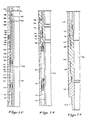
- FIGS. 2A to 2G are half, vertical, sectional views of a tool of the invention;
- FIGS. 3A and 3B show parts of the tool of Fig. 2 in more detail;
- FIG. 4 shows one embodiment of ratchet slot which may be used; and
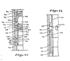
- FIG. 5 is a schematic vertical sectional view of part of a tool of the invention, including another embodiment of access valve.
- Referring to Fig. 1, the present invention is shown schematically incorporated in a perforating gun firing string deployed in an offshore oil or gas well,
Platform 2 is shown positioned over a submerged oil or gas well bore 4 located in sea floor 6, well bore 4 penetrating potential producing formation 8. Well bore 4 is shown to be lined withsteel casing 10, which is cemented into place. A subsea conduit 12 extends from thedeck 14 ofplatform 2 into asubsea wellhead 16, which includes ablowout preventer 18 therein.Platform 2 carries aderrick 20 thereon, as well as a hoistingapparatus 22, and a pump 24 which communicates with the well bore 4 viacontrol conduit 26, which extends belowblowout preventer 18. - A perforating gun firing string 30 is shown disposed in well bore 4, with
blowout preventer 18 closed thereabout. Perforating gun firing string 30 includes upperdrill pipe string 32 which extends downward fromplatform 2 towellhead 16, below which extendsintermediate pipe string 36.Slip joint 38 may be included instring 36 to compensate for vertical motion imparted toplatform 2 by wave action;slip joint 38 may be similar to that disclosed in U.S. Patent No. 3,354,950 to Hyde. Belowslip joint 38intermediate string 36 extends downwardly to perforatinggun firing tool 50 of present invention. Belowfiring tool 50 islower pipe string 40, extending totubing seal assembly 42, which stabs intopacker 44. When set, packer 44 isolates well boreannulus 46 from lowerwell bore annulus 48.Packer 44 may be any suitable packer well known in the art, such as, for example, a Baker Oil Tool Model D packer, an Otis Engineering Corporation type W packer, or Halliburton Services CHAMP®, RTTS or EZ DRILL® SV packers. Below the tubing seal assembly is perforatinggun 52, which may be any type of tubing pressure actuated perforating gun known in the art. Particularly preferred is the perforating gun with time delay firing mechanism disclosed in U.S. Patent No. 4,614,156 to Colle et al.Perforating gun 52 is actuated by a pressureresponsive firing head 54 located in the pipe string belowpacker 44. - Referring to Figs. 2A-2G,
tool 50 is shown in section, commencing at the bottom of the tool withlower adapter 100 havingthreads 102 therein at its lower end, wherebytool 50 is secured to lowerpipe string 40.Lower adapter 100 is secured tonitrogen valve housing 104 at threadedconnection 106,housing 104 containing a valve assembly (not shown), such as is well known in the art, inlateral bore 108 in the wall thereof, from which extends up longitudinalnitrogen charging channel 110. - Valve
housing 104 is secured by threadedconnection 112 at its outer upper end totubular pressure case 114, and by threaded connection 116 at its inner upper end togas chamber mandrel 118,case 114 andmandrel 118 defining pressurizedgas chamber 120 andlower oil chamber 122, the two being separated by floatingannular piston 124. - The lower end of
oil channel coupling 126 extends betweencase 114 andgas chamber mandrel 118, and is secured to the upper end ofcase 114 at threadedconnection 128. A plurality of longitudinal oil channels 130 (one shown) extend from the lower end ofcoupling 126 to the upper end thereof. Radially drilled oil fillports 132 extend from the exterior oftool 50, intersecting channels 130 and are closed withplugs 134.Annular shoulder 136 extends radially inward frominner wall 138 ofcoupling 126. The upper end ofcoupling 126, including annular overshot 127, is secured at threadedconnection 140 to the lower end ofratchet case 142, through which oil fillports 144 extend atannular shoulder 146, being closed byplugs 148. At the upper end ofratchet case 142 are additional oil fillports 150 closed byplugs 152 andopen pressure ports 154. -
Ratchet slot mandrel 156 extends downward within the upper end ofoil channel coupling 126.Annular ratchet chamber 158 is defined betweenmandrel 156 andcase 142. Thelower exterior 160 ofmandrel 156 is of substantially uniform diameter, while the upper exterior 162 is of greater diameter so as to provide sufficient wall thickness forratchet slot 164. Fig. 4 shows the pattern ofratchet slot 164 extending 180° around the exterior ofratchet slot mandrel 156. The same pattern is repeated on the second 180° of the exterior ofmandrel 156, making acontinuous slot 164 aroundmandrel 156. -
Ball sleeve assembly 166 surroundsratchet slot mandrel 156, and comprises lower sleeve 168 including radially outwardly extendingannular shoulder 170 havingannular piston seat 172 thereon. Aboveshoulder 170, ratchetpiston support surface 173 extends to the upper end of lower sleeve 168, which is overshot by the lower end ofupper sleeve 174 havingannular piston seat 176 thereon, and to which is secured at threadedconnection 178. Ball sleeve 180 is disposed at the top ofupper sleeve 174, and is secured thereto atswivel bearing race 182 by a plurality ofbearings 184. Tworatchet balls 186 each extend into aball seat 188 on diametrically opposite sides of ball sleeve 180 and into aratchet slot 164 of semicircular cross-section. Due to this structure, whenballs 186 follow the path ofslots 164, ball sleeve 180 rotates with respect toupper sleeve 174, the remainder ofball sleeve assembly 166 does not rotate, and only longitudinal movement is transmitted to ratchetmandrel 156 byballs 186. - Lower
annular ratchet piston 190 and upperannular ratchet piston 192 ride onpiston support surface 173 on lower sleeve 168,coil spring 194 being disposed therebetween.Lower ratchet piston 190 carriesradial sealing surface 196 on its lower end, whileupper ratchet piston 192 carriesradial sealing surface 198 on its upper end. - The
upper end 200 ofratchet slot mandrel 156 is secured at threadedconnection 202 toextension mandrel 204 havingrelief ports 208 extending therethrough. Annularupper oil chamber 210 is defined byratchet case 142 andextension mandrel 204. Annular floatingpiston 212 slidingly seals the bottom ofupper oil chamber 210 and divides it from wellfluid chamber 214 into whichpressure ports 154 opens. The upper end ofratchet case 142 is secured at threadedconnection 218, toextension case 216, which surroundsextension mandrel 204. -
Circulation housing 220 is threaded at 222 toextension case 216, and possesses a plurality of circumferentially spaced radially extendingcirculation ports 224 extending through the wall thereof. A plurality ofapertures 226 are provided to prevent fluid lock whencirculation ports 224 are in communication with the interior bore oftube 50. -
Circulation port sleeve 228 is threaded toextension mandrel 204 at 230.Valve apertures 232 extend through the wall ofcirculation valve sleeve 238, and are isolated fromcirculation ports 224 byannular seal 234, which is disposed in seal recess 236 formed by the junction ofcirculation valve sleeve 228 withdisplacement valve sleeve 238, the two being threaded together at 240. Abovevalve apertures 232 isannular seal 242 disposed in a groove on external surface ofdisplacement valve sleeve 238. - Above
valve apertures 232, operatingmandrel 260 extends upwardly to exteriorannular recess 267, which separatesannular shoulder 268 from the main body ofmandrel 260. -
Collet sleeve 270, havingcollet fingers 272 extending downward therefrom, engages operatingmandrel 260 through the accommodation of radially inwardly extendingprotuberances 274 byannular recess 267. As is readily noted in Fig. 2G,protuberances 274 and the lower portions offingers 272 are confined between the exterior ofmandrel 260 and the interior ofcirculation displacement housing 220. - At the upper end of
collet sleeve 270, coupling 276 comprisingflanges annular recess 282 therebetween, gripscoupling 284, comprising inwardly extendingflanges 286 and 288 withinterior recess 290 therebetween, on each of twoball operating arms 292.Couplings 276 and 284 are maintained in engagement by their location inannular recess 296 betweenball case 294, which is threaded at 295 tocirculation displacement housing 220, andball housing 298.Ball housing 298 is of substantially tubular configuration, having a lowersmaller diameter portion 300 and an upper,larger diameter portion 302 which has twowindows 304 cut through the wall thereof to accommodate the inward protrusion oflugs 306 from each of the twoball operating arms 292.Windows 304 extend fromshoulder 311 upward toshoulder 314 adjacent threadedconnection 316 withball support 340. On the exterior of theball housing 298, two longitudinal channels (location shown by arrow 308) of arcuate cross-section and circumferentially aligned withwindows 304, extend from shoulder 310 upward toshoulder 311.Ball operating arms 292, which are of substantially the same arcuate cross-section aschannels 308 andlower portion 302 ofball housing 298, lie inchannels 308 and acrosswindows 304, and are maintained in place by theinterior wall 318 ofball case 294 and the exterior ofball support 340. - The interior of
ball housing 298 possesses lowerannular seat recess 320, within whichannular ball seat 322 is disposed, being biased upwardly againstball 330 byring spring 324.Surface 326 oflower seat 322 comprises a metal sealing surface, which provides a sliding seal with theexterior 332 ofvalve ball 300. -
Valve ball 330 includes adiametrical bore 334 therethrough, of substantially the same diameter asbore 328 ofball housing 298. Two lug recesses 336 extend from theexterior 332 ofvalve ball 330 to bore 334. - The
upper end 342 ofball support 340 extends intoball housing 298, and carries upperball seat recess 344 in which annularupper ball seat 346 is disposed.Upper ball seat 346 possesses arcuatemetal sealing surface 348 which slidingly seals against theexterior 332 ofvalve ball 330. Whenball housing 298 is made up withball support 340, lower and upper ball seats 322 and 346 are biased into sealing engagement withvalve ball 330 byspring 324. - Exterior
annular shoulder 350 onball support 340 is contacted by the lower ends 352 ofsplines 354 on the exterior ofball case 294, whereby the assembly ofball housing 294,ball operating arms 292,valve ball 330, ball seats 322 and 346 andspring 324 are maintained in position inside ofball case 294.Splines 354 engagesplines 356 on the exterior ofball support 340, and thus rotation of theball support 340 andball housing 298 withinball case 298 is prevented. -
Upper adapter 360 protrudes at itslower end 362 betweenball case 298 andball support 340, sealing therebetween, when made up withball support 340 at threadedconnection 364. The upper end ofupper adapter 360 carries on itsinterior threads 366 for making up with portions of drill string abovetool 50. - When
valve ball 330 is in its open position, as shown in Fig. 2G, a "full open" bore 370 extends throughouttool 50, providing an unimpeded path for formation fluids and/or for perforating guns, wireline instrumentation, etc. - Referring to Figs. 1 through 4, operation of the
firing tool 50 of the present invention is described hereafter. - As
tool 50 is run into the well on string 30 it is in the position shown in Figs. 2A-G, withball valve 330 open andcirculation valves 232 closed. With respect to Fig. 4,balls 186 will be in position "a" inslots 164 astool 50 is run into the well bore 10. - As
tool 50 is being run into the well, well fluids enter the pipe string through perforations in the string belowtool 50 and pass throughflow valve 330 to form a fluid cushion abovetool 50. Astool 50 descends, the hydrostatic pressure increases on it. The effect of this pressure, communicated to the tool throughhydrostatic ports 154, is to move floatingpiston 212 downward. This increases the pressure on the fluid inupper oil chamber 210, which is in fluid communication withratchet chamber 158.Lower ratchet piston 190 is pushed downwards, movingball sleeve assembly 166 andballs 186 downwards. The oil is prevented from by-passingpiston 190 by the metal to metal seal of sealingsurface 196 onpiston seat 172. Whenballs 186 reach position "b" shown on Fig. 5,piston 190 reaches overshot 127 which prevents further downward movement. Further fluid pressure acts onshoulder 170 of lower sleeve 168, spreadingpiston seat 172 from seatingsurface 196, breaking the seal and dumping oil past lower sleeve 168 which equalizes the pressures on both sides ofpiston 190, stopping further movement ofball sleeve assembly 166. - In order to shut the cushion in at the desired depth, it is necessary to close the flow valve, to prevent any further well fluid entering the string, and to open the circulating valve. To perform this operation, the annulus pressure is increased, moving
balls 186 to position "b". The annulus pressure is then reduced. This reduction in pressure causes floatingpiston 212 to move upward, pulling ball sleeve assembly 116 upward, and causingballs 186 to move into positions "c". This operation effects no change in the position of the valves. - In order to close the
flow valve 330 to shut the cushion in, pressure is increased inannulus 46 by pump 24 viacontrol conduit 26. This increase in pressure is transmitted throughpressure ports 154 into wellfluid chamber 214, where it acts upon floatingpiston 212, moving it downward. The pressure is transmitted through the fluid inupper oil chamber 210 to ratchetchamber 158, where the pressurized oil presses onlower ratchet piston 190. The oil is prevented from bypassingpiston 190 by the metal to metal seal of sealingsurface 196 onpiston seat 172.Piston 190 therefore pushes againstshoulder 170 on lower sleeve 168, which in turn pullsupper sleeve 174, ball sleeve 180 andballs 186 downward inslots 164 to position "d". This movesratchet mandrel 156 downwards, which pullsextension mandrel 204,circulation port sleeve 228,circulation valve sleeve 238 andoperating mandrel 260 downwards. Operatingmandrel 260 pullscollet sleeve 270 downwards, which pullsarms 292 and rotatesflow valve 330.Flow valve 330 is now closed andcirculation ports 224 are aligned withapertures 232 as shown in Figs. 3A and B. The annulus pressure is then released. - When the annulus pressure is decreased, the pressurized nitrogen in
chamber 120 pushes against floatingpiston 124, and the pressure is transmitted throughlower oil chamber 122, channels 130 and ratchetchamber 158 againstupper ratchet piston 192. Aspiston 192 is biased againstpiston seat 176, a metal to metal seal is effected at sealingsurface 198 andball sleeve assembly 166 is pushed upwards. Theratchet balls 186 are now in position "e" inslots 164 as shown in Fig. 4. At this point further travel ofupper ratchet piston 192 is prevented byannular shoulder 146, and further action of the pressurized fluidspreads sealing surface 198 fromseat 176. Fluid pressures are thereby equalized on either side ofpiston 192, preventing further travel ofball sleeve assembly 166 andballs 186 remain in position "e". - The string is then run further into the well until the perforating gun reaches the position adjacent to the formation to be perforated, and the packer is set.
- The packer is then tested by again pressuring the
upper annulus 46. This increase of pressure movesballs 186 to positions "f" inslots 164 shown in Fig. 4, by the same means as described above. The pressure is then decreased, movingballs 186 to position "g" where they shoulder againstslots 164 and effect upwards movement ofratchet mandrel 156,extension mandrel 204,circulation valve sleeve 238, operatingmandrel 260 andcollet sleeve 270. This has the effect of closingcirculation ports 224 by movingapertures 232 out of alignment andopening flow valve 330 by means ofarms 292. - The packer is then tested by increasing the annulus pressure. This increase in pressure moves the
ball sleeve assembly 166 upwards untilballs 186 are in position "h" shown in Fig. 4. At this point further travel is prevented bylower pistons 190 reaching overshot 127 and fluid breaking the seal and equalizing the pressure on both sides ofpiston 190, and no change in valve positions is effected. - When the packer test is completed the annulus pressure is released, moving
balls 186 to position "j" shown on Fig. 4. The annulus is then pressured to moveballs 186 into position "k" inslot 164 shown on Fig. 4, at which point flowvalve 330 closes andcirculation valve 232 opens. Pressure is then released, movingballs 186 to position "1". - Pressure is then increased in the annulus until a sufficient pressure to actuate the firing
head 54 is reached. This increase in pressure movesballs 186 to position "m" shown on Fig. 5. Once the firinghead 54 has been actuated, the pressure in the annulus is decreased, moving theballs 186 to position "n" where theflow valve 330 is opened and thecirculation valves 232 are closed. The pressure in the tubing string can then be bled off before the perforating gun fires, if a time delay firing system is used, creating a suitable underbalance at the time of perforation. - In an alternative mode of operation, the
tool 50 may be run down the well in the position shown in Figs. 3A and B, withball valve 330 closed andcirculation valves 232 open. This would be done if no cushion was desired, or if a cushion is to be supplied by fluids injected from the surface after the perforatinggun 52 is in position. In this mode theballs 186 would start at position "d" on Fig. 5, and would thereafter follow the same cycle. - An alternative embodiment of the present invention is shown in Fig. 5. The circulation valve with slideable sleeve of the above described embodiment is replaced by
injection valve 400. Thevalve 400 is lodged inbore 402 which connects theexterior 404 ofvalve housing 406 withinterior 408. Thehead 410 ofvalve 400 is maintained in sealing contact with the slopingshoulders 412 ofbore 402 bycoil spring 414. Thespring 414 is selected so that it will begin to compress at a predetermined pressure dependent upon the particular circumstances in which the invention is to be used, which is readily calcuable by those of ordinary skill in the art. When this pressure is present in the annulus fluid, thehead 410 is forced out of sealing contact withshoulders 412 and fluid flowspast valve 400 throughbore 402 into the interior 408. - When the pressure in the annulus is reduced below the predetermined pressure,
spring 414 forces head 410 back into sealing contact withshoulders 412, closingvalve 400 and preventing flow in either direction throughbore 402. -
Valve housing 406 is connected at its upper end through upper adapter 416 to the housing of a conventional tubing valve which prevents flow through the pipe string when closed. Preferably, an annulus pressure actuated tubing valve is used, arranged so that it closes at the same annulus pressure which opensinjection valve 400 and opens when the pressure has dropped to the point at whichinjection valve 400 closes. Particularly preferred is the Halliburton APR ®-N Tester Valve. -
Valve housing 408 is connected at its lower end throughlower adaptor 418 to the lower string with thepacker 44 and the pressureresponsive firing head 54 and perforatinggun 52. - The operation of this embodiment follows the same cycles as the operation of a preferred embodiment described above. The pipe string is run into the well with the tubing valve open and the injection valve shut. When the desired cushion depth is reached, the tubing is shut in by increasing the annulus pressure to close the tubing valve and open the injection valve. The pipe string then is run further in until the perforating gun is in position. The packer is set, and the annulus pressure released to open the tubing valve and close the injection valve. The annulus pressure is increased to test the packer, but is left below the predetermined pressure so that the valves do not change position. When the packer tests satisfactorily, the annulus pressure is increased to open the injection valve and close the tubing valve, and then increased to a sufficient pressure to actuate the firing head. Once the firing head is actuated, the annulus pressure is released, closing the injection valve and opening the tubing valve so that pressure in the tubing can be bled off.
- Additional advantages and modifications will be readily apparent to those skilled in the art. The invention in its broader aspects is therefore not limited to the specific details, representative apparatus or the illustrative example shown and described. Accordingly, departures may be made from the detail without departing from the spirit or scope of the disclosed general inventive concept.
Claims (9)
Applications Claiming Priority (2)
| Application Number | Priority Date | Filing Date | Title |
|---|---|---|---|
| US07/040,219 US4804044A (en) | 1987-04-20 | 1987-04-20 | Perforating gun firing tool and method of operation |
| US40219 | 2001-10-29 |
Publications (2)
| Publication Number | Publication Date |
|---|---|
| EP0288239A2 true EP0288239A2 (en) | 1988-10-26 |
| EP0288239A3 EP0288239A3 (en) | 1989-10-11 |
Family
ID=21909786
Family Applications (1)
| Application Number | Title | Priority Date | Filing Date |
|---|---|---|---|
| EP88303501A Ceased EP0288239A3 (en) | 1987-04-20 | 1988-04-19 | Perforating gun firing tool |
Country Status (7)
| Country | Link |
|---|---|
| US (1) | US4804044A (en) |
| EP (1) | EP0288239A3 (en) |
| AU (1) | AU593732B2 (en) |
| CA (1) | CA1303971C (en) |
| DK (1) | DK198988A (en) |
| MY (1) | MY102797A (en) |
| NO (1) | NO881684L (en) |
Cited By (5)
| Publication number | Priority date | Publication date | Assignee | Title |
|---|---|---|---|---|
| EP0370652A2 (en) * | 1988-11-23 | 1990-05-30 | Halliburton Company | Downhole well tool valve |
| US5044437A (en) * | 1989-06-20 | 1991-09-03 | Institut Francais Du Petrole | Method and device for performing perforating operations in a well |
| EP0554013A1 (en) * | 1992-01-23 | 1993-08-04 | Halliburton Company | Drill stem testing with tubing conveyed perforation |
| EP0606981A1 (en) * | 1993-01-14 | 1994-07-20 | Halliburton Company | Downhole valve apparatus |
| WO2019105861A1 (en) * | 2017-11-29 | 2019-06-06 | Dynaenergetics Gmbh & Co. Kg | Hydraulic underbalance initiated safety firing head, well completion apparatus incorporating same, and method of use |
Families Citing this family (14)
| Publication number | Priority date | Publication date | Assignee | Title |
|---|---|---|---|---|
| US5509482A (en) * | 1994-09-26 | 1996-04-23 | Trico Industries, Inc. | Perforation trigger bypass assembly and method |
| US6598682B2 (en) * | 2000-03-02 | 2003-07-29 | Schlumberger Technology Corp. | Reservoir communication with a wellbore |
| US7284612B2 (en) * | 2000-03-02 | 2007-10-23 | Schlumberger Technology Corporation | Controlling transient pressure conditions in a wellbore |
| US7013977B2 (en) * | 2003-06-11 | 2006-03-21 | Halliburton Energy Services, Inc. | Sealed connectors for automatic gun handling |
| US8006779B2 (en) * | 2009-02-18 | 2011-08-30 | Halliburton Energy Services, Inc. | Pressure cycle operated perforating firing head |
| US8534361B2 (en) * | 2009-10-07 | 2013-09-17 | Baker Hughes Incorporated | Multi-stage pressure equalization valve assembly for subterranean valves |
| GB2479552B (en) * | 2010-04-14 | 2015-07-08 | Aker Subsea Ltd | Subsea wellhead providing controlled access to a casing annulus |
| CA2983660C (en) * | 2015-05-06 | 2019-12-17 | Thru Tubing Solutions, Inc. | Multi-cycle circulating valve assembly |
| US11773690B2 (en) * | 2017-11-15 | 2023-10-03 | Schlumberger Technology Corporation | Combined valve system and methodology |
| US10907447B2 (en) | 2018-05-27 | 2021-02-02 | Stang Technologies Limited | Multi-cycle wellbore clean-out tool |
| US10927623B2 (en) | 2018-05-27 | 2021-02-23 | Stang Technologies Limited | Multi-cycle wellbore clean-out tool |
| US10927648B2 (en) | 2018-05-27 | 2021-02-23 | Stang Technologies Ltd. | Apparatus and method for abrasive perforating and clean-out |
| US11346184B2 (en) | 2018-07-31 | 2022-05-31 | Schlumberger Technology Corporation | Delayed drop assembly |
| US11668147B2 (en) | 2020-10-13 | 2023-06-06 | Thru Tubing Solutions, Inc. | Circulating valve and associated system and method |
Citations (6)
| Publication number | Priority date | Publication date | Assignee | Title |
|---|---|---|---|---|
| EP0092476A2 (en) * | 1982-04-16 | 1983-10-26 | Schlumberger Technology Corporation | Pressure activated well perforating technique |
| US4485876A (en) * | 1983-09-26 | 1984-12-04 | Baker Oil Tools, Inc. | Valving apparatus for downhole tools |
| US4544034A (en) * | 1983-03-31 | 1985-10-01 | Geo Vann, Inc. | Actuation of a gun firing head |
| US4633952A (en) * | 1984-04-03 | 1987-01-06 | Halliburton Company | Multi-mode testing tool and method of use |
| US4655298A (en) * | 1985-09-05 | 1987-04-07 | Halliburton Company | Annulus pressure firer mechanism with releasable fluid conduit force transmission means |
| EP0155128B1 (en) * | 1984-03-08 | 1988-08-03 | Halliburton Company | Devices for actuating explosive charges in wellbores, and methods of perforating boreholes |
Family Cites Families (6)
| Publication number | Priority date | Publication date | Assignee | Title |
|---|---|---|---|---|
| US3675718A (en) * | 1970-09-11 | 1972-07-11 | Exxon Production Research Co | Conducting operations in a well through a normally closed valve |
| US4560000A (en) * | 1982-04-16 | 1985-12-24 | Schlumberger Technology Corporation | Pressure-activated well perforating apparatus |
| US4484632A (en) * | 1982-08-30 | 1984-11-27 | Geo Vann, Inc. | Well completion method and apparatus |
| US4564076A (en) * | 1983-04-11 | 1986-01-14 | Geo Vann, Inc. | Well completion method and apparatus |
| US4614156A (en) * | 1984-03-08 | 1986-09-30 | Halliburton Company | Pressure responsive explosion initiator with time delay and method of use |
| US4901802A (en) * | 1987-04-20 | 1990-02-20 | George Flint R | Method and apparatus for perforating formations in response to tubing pressure |
-
1987
- 1987-04-20 US US07/040,219 patent/US4804044A/en not_active Expired - Fee Related
-
1988
- 1988-04-12 DK DK198988A patent/DK198988A/en unknown
- 1988-04-13 AU AU14582/88A patent/AU593732B2/en not_active Ceased
- 1988-04-19 EP EP88303501A patent/EP0288239A3/en not_active Ceased
- 1988-04-19 MY MYPI88000389A patent/MY102797A/en unknown
- 1988-04-19 NO NO881684A patent/NO881684L/en unknown
- 1988-04-20 CA CA000564604A patent/CA1303971C/en not_active Expired - Fee Related
Patent Citations (6)
| Publication number | Priority date | Publication date | Assignee | Title |
|---|---|---|---|---|
| EP0092476A2 (en) * | 1982-04-16 | 1983-10-26 | Schlumberger Technology Corporation | Pressure activated well perforating technique |
| US4544034A (en) * | 1983-03-31 | 1985-10-01 | Geo Vann, Inc. | Actuation of a gun firing head |
| US4485876A (en) * | 1983-09-26 | 1984-12-04 | Baker Oil Tools, Inc. | Valving apparatus for downhole tools |
| EP0155128B1 (en) * | 1984-03-08 | 1988-08-03 | Halliburton Company | Devices for actuating explosive charges in wellbores, and methods of perforating boreholes |
| US4633952A (en) * | 1984-04-03 | 1987-01-06 | Halliburton Company | Multi-mode testing tool and method of use |
| US4655298A (en) * | 1985-09-05 | 1987-04-07 | Halliburton Company | Annulus pressure firer mechanism with releasable fluid conduit force transmission means |
Cited By (8)
| Publication number | Priority date | Publication date | Assignee | Title |
|---|---|---|---|---|
| EP0370652A2 (en) * | 1988-11-23 | 1990-05-30 | Halliburton Company | Downhole well tool valve |
| EP0370652A3 (en) * | 1988-11-23 | 1991-10-23 | Halliburton Company | Downhole well tool valve |
| US5044437A (en) * | 1989-06-20 | 1991-09-03 | Institut Francais Du Petrole | Method and device for performing perforating operations in a well |
| EP0554013A1 (en) * | 1992-01-23 | 1993-08-04 | Halliburton Company | Drill stem testing with tubing conveyed perforation |
| EP0606981A1 (en) * | 1993-01-14 | 1994-07-20 | Halliburton Company | Downhole valve apparatus |
| WO2019105861A1 (en) * | 2017-11-29 | 2019-06-06 | Dynaenergetics Gmbh & Co. Kg | Hydraulic underbalance initiated safety firing head, well completion apparatus incorporating same, and method of use |
| US10865626B2 (en) | 2017-11-29 | 2020-12-15 | DynaEnergetics Europe GmbH | Hydraulic underbalance initiated safety firing head, well completion apparatus incorporating same, and method of use |
| US11408258B2 (en) | 2017-11-29 | 2022-08-09 | DynaEnergetics Europe GmbH | Hydraulic underbalance initiated safety firing head, well completion apparatus incorporating same, and method of use |
Also Published As
| Publication number | Publication date |
|---|---|
| US4804044A (en) | 1989-02-14 |
| NO881684D0 (en) | 1988-04-19 |
| AU593732B2 (en) | 1990-02-15 |
| MY102797A (en) | 1992-10-31 |
| AU1458288A (en) | 1988-10-20 |
| DK198988D0 (en) | 1988-04-12 |
| EP0288239A3 (en) | 1989-10-11 |
| CA1303971C (en) | 1992-06-23 |
| DK198988A (en) | 1988-10-21 |
| NO881684L (en) | 1988-10-21 |
Similar Documents
| Publication | Publication Date | Title |
|---|---|---|
| US4804044A (en) | Perforating gun firing tool and method of operation | |
| US4509604A (en) | Pressure responsive perforating and testing system | |
| US5048611A (en) | Pressure operated circulation valve | |
| US7926575B2 (en) | Hydraulic lockout device for pressure controlled well tools | |
| US6216785B1 (en) | System for installation of well stimulating apparatus downhole utilizing a service tool string | |
| US5398760A (en) | Methods of perforating a well using coiled tubing | |
| US5174379A (en) | Gravel packing and perforating a well in a single trip | |
| US4116272A (en) | Subsea test tree for oil wells | |
| EP0187690B1 (en) | Downhole tool with liquid spring | |
| US4560000A (en) | Pressure-activated well perforating apparatus | |
| US5180015A (en) | Hydraulic lockout device for pressure controlled well tools | |
| US4144937A (en) | Valve closing method and apparatus for use with an oil well valve | |
| EP0089740B1 (en) | Annulus pressure responsive tester valve | |
| CA2445870C (en) | Automatic tubing filler | |
| US6199632B1 (en) | Selectively locking locator | |
| US5297629A (en) | Drill stem testing with tubing conveyed perforation | |
| US4523643A (en) | Well perforating and completion apparatus and associated method | |
| EP0301734B1 (en) | Downhole circulation valve | |
| EP0190864B1 (en) | Pressure-responsive downhole well tool | |
| EP0212814B1 (en) | Method of operating apr valve in wellbore | |
| US4655288A (en) | Lost-motion valve actuator | |
| US4917189A (en) | Method and apparatus for perforating a well | |
| US4690227A (en) | Gun firing head | |
| CA3145373A1 (en) | Modified float collar and methods of use | |
| US10465478B2 (en) | Toe valve |
Legal Events
| Date | Code | Title | Description |
|---|---|---|---|
| PUAI | Public reference made under article 153(3) epc to a published international application that has entered the european phase |
Free format text: ORIGINAL CODE: 0009012 |
|
| AK | Designated contracting states |
Kind code of ref document: A2 Designated state(s): DE ES FR GB IT NL |
|
| PUAL | Search report despatched |
Free format text: ORIGINAL CODE: 0009013 |
|
| AK | Designated contracting states |
Kind code of ref document: A3 Designated state(s): DE ES FR GB IT NL |
|
| 17P | Request for examination filed |
Effective date: 19900215 |
|
| 17Q | First examination report despatched |
Effective date: 19910521 |
|
| STAA | Information on the status of an ep patent application or granted ep patent |
Free format text: STATUS: THE APPLICATION HAS BEEN REFUSED |
|
| 18R | Application refused |
Effective date: 19921225 |