EP0289749A1 - Device for unwinding a web from a roll - Google Patents
Device for unwinding a web from a roll Download PDFInfo
- Publication number
- EP0289749A1 EP0289749A1 EP88103997A EP88103997A EP0289749A1 EP 0289749 A1 EP0289749 A1 EP 0289749A1 EP 88103997 A EP88103997 A EP 88103997A EP 88103997 A EP88103997 A EP 88103997A EP 0289749 A1 EP0289749 A1 EP 0289749A1
- Authority
- EP
- European Patent Office
- Prior art keywords
- roll
- support arms
- shaft
- web
- axis
- Prior art date
- Legal status (The legal status is an assumption and is not a legal conclusion. Google has not performed a legal analysis and makes no representation as to the accuracy of the status listed.)
- Granted
Links
Images


Classifications
-
- B—PERFORMING OPERATIONS; TRANSPORTING
- B65—CONVEYING; PACKING; STORING; HANDLING THIN OR FILAMENTARY MATERIAL
- B65H—HANDLING THIN OR FILAMENTARY MATERIAL, e.g. SHEETS, WEBS, CABLES
- B65H19/00—Changing the web roll
- B65H19/10—Changing the web roll in unwinding mechanisms or in connection with unwinding operations
- B65H19/12—Lifting, transporting, or inserting the web roll; Removing empty core
- B65H19/126—Lifting, transporting, or inserting the web roll; Removing empty core with both-ends supporting arrangements
Abstract
Description
Die Erfindung betrifft eine Vorrichtung zum Abwickeln einer Materialbahn von einer Rolle mit zwei quer zur Bahn in Abstand voneinander hochschwenkbar gelagerten Tragarmen, die Mittel zum Aufnehmen und drehbaren Halten der Rolle aufweisen.The invention relates to a device for unwinding a web of material from a roll with two support arms which are mounted so that they can be swiveled up at a distance from one another transversely to the web and which have means for receiving and rotatably holding the roll.
Vorrichtungen dieser Art dienen insbesondere zum Abrollen von Papierbahnen in der papierverarbeitenden Industrie.Devices of this type are used in particular for unrolling paper webs in the paper processing industry.
Die abzuwickelnde Papierrolle wird zwischen den Tragarmen eingehängt und zum Abwickeln angehoben. Beim achslosen Abwickeln einer auf eine Hülse aufgewickelten Papierbahn werden dazu zwei an den Tragarmen drehbar befestigte Spannköpfe in die beiden seitlichen Öffnungen der Wickelhülse eingefahren. Derartige Abwickelvorrichtungen sind z.B. in dem DE-GM 85 11 986 und in der DE-OS 29 51 336 beschrieben.The paper roll to be unwound is suspended between the support arms and raised for unwinding. When unwinding a paper web wound onto a tube, two clamping heads rotatably fastened to the support arms are inserted into the two lateral openings of the winding tube. Such unwinding devices are described for example in DE-GM 85 11 986 and in DE-OS 29 51 336.
Üblicherweise erfolgt die Zufuhr einer neuen Rolle zum Rollenwechsel auf Unterflurförderern, die die Rolle in den Aufnahmebereich der Spannköpfe fördern, die zur Aufnahme einer Rolle auseinander und nach unten gefahren werden können. Bei mehreren, in Bahnlaufrichtung hintereinander angeordneten Abrollungen ist es für einen schnellen Rollenwechsel vorteilhaft, die neuen Rollen von der Seite, quer zur Bahnlaufrichtung zuzuführen. Bei Vorrichtungen mit in seitlichen Ständern befestigten Tragarmen muß dazu zwischen den Abrollstationen Platz gelassen werden, da die Ständer einer seitlichen Beschickung im Wege stehen, und es ist eine zusätzliche Förderung in Bahnlaufrichtung erforderlich, der die Rolle in die Aufnahmeposition der Spannköpfe bringt.Usually, a new roll for changing rolls is fed on underfloor conveyors which convey the roll into the receiving area of the clamping heads, which can be moved apart and down to receive a roll. If there are several unwinds arranged one behind the other in the web running direction, it is advantageous for a quick roll change to feed the new rolls from the side, transversely to the web running direction. In devices with support arms attached in side stands, space must be left between the unwinding stations because the stands stand in the way of a side loading, and an additional conveying in the direction of web travel is required, which brings the roll into the receiving position of the clamping heads.
Um diesen zusätzliche Förderung zu vermeiden und um einen platzsparenderen Aufbau zu erreichen, sind in der gattungsgemäßen Vorrichtung nach dem DE-GM 85 11 986 die in einem Gestell aufgehängten Tragbalken an der Beschickungsseite zum Einfahren einer neuen Rolle hochschwenkbar. Die Tragbalken schwenken zur Aufnahme einer neuen Rolle in eine vertikale Stellung, anschließend wird durch Verkürzung der Tragarme die Rolle angehoben. An dieser Vorrichtung ist nachteilig, daß alle Kräfte von horizontalen Trägern des Gestells übertragen werden, das daher aus Stabilitätsgründen sehr schwer ausgeführt sein muß.In order to avoid this additional funding and to achieve a more space-saving structure, the supporting beams suspended in a frame in the generic device according to DE-GM 85 11 986 can be swiveled up on the loading side for insertion of a new roll. The support beams swivel into a vertical position to accommodate a new roll, then the roll is raised by shortening the support arms. A disadvantage of this device is that all forces are transmitted by horizontal supports of the frame, which must therefore be made very difficult for reasons of stability.
Es sind auch bereits Vorrichtungen bekannt, bei denen die Tragarme an Ständern vertikal beweglich befestigt sind und zusätzlich zum Einfahren einer neuen Rolle hochgeschwenkt werden können. Zum Anheben in die Abwickelposition werden die in etwa waagerecht abstehenden Tragarme vertikal in den Ständern verfahren. Dies verlangt eine aufwendige senkrechte Führung der Tragarme in den seitlichen Ständern.Devices are also already known in which the support arms are fastened to stands in a vertically movable manner and can additionally be swiveled up in order to retract a new roll. To lift it into the unwinding position, the approximately horizontally projecting support arms are moved vertically in the stands. This requires complex vertical guidance of the support arms in the side stands.
Der Erfindung liegt die Aufgabe zugrunde, eine gattungsgemäße Vorrichtung zu schaffen, die konstruktiv einfach und platzsparend aufbaubar ist.The invention has for its object to provide a generic device that is structurally simple and space-saving.
Diese Aufgabe wird durch die Merkmale des Patentanspruchs 1 gelöst.This object is achieved by the features of patent claim 1.
Nach der Erfindung läßt sich das Hochheben der Rolle in die Abwickelposition durch eine Schwenkbewegung bewerkstelligen, so daß eine aufwendige vertikale Führung überflüssig ist. Gleichzeitig lassen sich die Rollenaufnahmeeinrichtungen an den Enden der Tragarme in horizontaler Richtung bewegen, so daß beim Rollenwechsel die neue Rolle nicht quer zu ihrer Achse positioniert werden muß. Dieses Prinzip ermöglicht so sowohl einen platzsparenden Aufbau, als auch eine vereinfachte Konstruktion, da die Tragarme beim Hochschwenken am Boden abgestützt werden können.According to the invention, the lifting of the roll into the unwinding position can be accomplished by a pivoting movement, so that an expensive vertical guide is unnecessary. At the same time, the roll receiving devices can be moved at the ends of the support arms in a horizontal direction, so that the new roll does not have to be positioned transversely to its axis when changing rolls. This principle enables both a space-saving structure and a simplified construction, since the support arms can be supported on the ground when swiveling up.
Als weiterer Vorteil tritt hinzu, daß sich die Tragarme in Abwickelposition in etwa senkrecht stellen lassen und so die an den Schwenkachsen wirkenden Drehmomente wesentlich verringert werden können. Bei einer nachträglichen axialen Korrektur der Abwickelposition werden so die Elemente, die ein Schwenken der Tragarme verhindern, erheblich weniger belastet.Another advantage is that the support arms can be set approximately vertically in the unwinding position and the torques acting on the swivel axes can be significantly reduced. In the event of a subsequent axial correction of the unwinding position, the elements which prevent the support arms from pivoting are thus subjected to considerably less stress.
Die Unteransprüche enthalten konstruktiv vorteilhafte Ausführungsformen der Erfindung.The subclaims contain constructively advantageous embodiments of the invention.
Während bei den Vorrichtungen nach den Ansprüchen 2 bis 6 die Horizontalbewegung der Schwenklager dadurch ermöglicht wird, daß die Tragarme hochschwenkbar in einer am Boden verfahrbaren Konstruktion gelagert sind, enthält der Patentanspruch 7 eine Ausführungsform, bei der die Tragarme an feststehenden Ständern über Hebel angelenkt sind.While in the devices according to
Die Zeichnungen dienen zur Erläuterung der Erfindung anhand vereinfacht dargestellter Ausführungsbeispiele.
- Figur 1 zeigt einen Querschnitt durch eine verfahrbare Vorrichtung. Die Tragarme sind zur besseren Sichtbarkeit um 90 ° gegenüber der Abwickelposition abgeschwenkt.
Figur 2 zeigt eine Seitenansicht einer Vorrichtung nach Figur 1 mit hochgeschwenkten Tragarmen.- Die Figuren 3 - 6 zeigen das Abwickeln und Aufnehmen einer neuen Rolle bei einer Vorrichtung nach Figur 1.
- Die
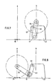
Figuren 7 und 8 zeigen als Prinzipskizze eine erfindungsgemäße Vorrichtung, bei der die Tragarme in feststehenden Ständern aufgehängt sind.
- Figure 1 shows a cross section through a movable device. The support arms are swiveled 90 ° from the unwinding position for better visibility.
- FIG. 2 shows a side view of a device according to FIG. 1 with the support arms pivoted up.
- FIGS. 3-6 show the unwinding and taking up of a new roll in a device according to FIG. 1.
- Figures 7 and 8 show a schematic diagram of a device according to the invention, in which the support arms are suspended in fixed stands.
Die in den Figuren 1 und 2 beschriebene erfindungsgemäße Vorrichtung ist auf zwei horizontalen Grundplatten 1, 2, die in einem Abstand größer als die maximale Rollenbreite voneinander angeordnet sind, quer zur Achse der abzuwickelnden Rolle 3 horizontal verfahrbar abgestützt, in Figur 2 von links nach rechts und umgekehrt.The device according to the invention described in Figures 1 and 2 is supported on two
Sie weist zwei Tragarme 4, 5 mit einander zugewandten Spannköpfen 6, 7 zur Aufnahme einer Papierrolle 3 auf, wobei die Tragarme 4, 5 auf einer Welle 8 verschiebbar und durch eine Paßfeder 9 drehfest befestigt sind. Die Welle 8 weist an beiden Enden freilaufende Rollen 10, 11 auf, mit denen sie auf den Grundplatten 1, 2 hin- und hergefahren werden kann. Die Lager 12 der Welle 8 in den Rollen 10,11 sind zugleich die Schwenklager für die Schwenkbewegung der Tragarme 4,5. Der Antrieb für diese Bewegung befindet sich an einer Seite (in Fig. 1 rechts) auf der Grundplatte 2.It has two
Er besteht aus einer Kolben-Zylinder-Einheit 13, die einerseits an der Grundplatte 2, andererseits an einem fahrbaren Wagen befestigt ist. Der Wagen baut sich aus zwei parallelen Seitenteilen 14, 15 auf, durch die an einem Ende die Welle 8 parallel zur Achse der Rolle 3 und frei drehbar geführt ist, so daß der Wagen auf der Welle 8 abgestützt ist. Das andere Ende des Wagens ist auf einer Rolle 16 abgestützt, die auf einer Welle 17 zwischen den beiden Seitenteilen 14, 15 sitzt und zwischen einer Führungsschiene 18 und der Grundplatte 2 läuft. Anstelle der Kolben-Zylinder-Einheit 13 kann als Antrieb ebenso ein Elektromotor mit Kette eingesetzt werden.It consists of a piston-
Damit die Vorrichtung auf beiden Seiten exakt gleich verfahren wird, enthält sie eine Gleichlaufvorrichtung. Diese besteht aus einer sich quer über die Arbeitsbreite erstreckenden Synchronwelle 19, die auf der Antriebsseite in dem Seitenteil 14 und auf der anderen Seite in einer am Ende der Welle 8 eingehängten Verbindungsplatte 20 drehbar gelagert ist. Auf beiden Enden der Synchronwelle 19 sind Ritzel 21, 22 befestigt, die jeweils in einer mit der jeweiligen Grundplatte 1, 2 verbundenen Zahnstange 23, 24 laufen. Am äußersten Ende der Synchronwelle 9 hinter der Verbindungsplatte 20 ist ein Rad 25 befestigt, das in einer Führungsschiene 26 mit U-förmigem Querschnitt läuft, um jederzeit den Eingriff des Ritzels 21 in die Zahnstange 23 sicherzustellen. Alternativ zu den Zahnstangen 23,24 können auch Triebstöcke oder Ketten eingesetzt werden.So that the device is moved exactly the same on both sides, it contains a synchronizing device. This consists of a
Anstelle nur eines Fahrantriebs mit einer Gleichlaufvorrichtung ist der Einsatz von zwei getrennten Antrieben an beiden Seiten möglich, wobei die Bewegung der beiden Antriebe aufeinander abgestimmt ist.Instead of only one travel drive with a synchronizing device, the use of two separate drives on both sides is possible, the movement of the two drives being coordinated with one another.
Zum Hoch- und Niederschwenken der Tragarme 4, 5 ist auf der Welle 8 im Bereich zwischen den beiden Seitenteilen 14, 15 ein Schwenkhebel 27 befestigt und mit einer Paßfeder 28 gegen Verdrehung gesichert. Am anderen Ende des Schwenkhebels 27 ist in einer Gabel eine Spindelmutter 29 um eine zur Welle 8 parallele Achse drehbar gelagert.For pivoting the
Durch die Spindelmutter 29 ist eine Gewindespindel 30 geführt, die von einem Getriebemotor 31 angetrieben wird, der an den Seitenteilen 14, 15 oberhalb der Rolle 16 drehbar befestigt ist. Mit dem Getriebemotor 31 läßt sich so der Hebel 27 schwenken, dadurch wird die Welle 8 gedreht, und die auf diesem befestigten Tragarme 4, 5 werden mitgeschwenkt. Anstelle des Spindelwerks 29,30 mit Getriebemotor 31 ist auch der Einsatz einer hydraulischen Kolben-Zylinder-Einheit möglich.A threaded
Der Abstand der Spannköpfe 6, 7 voneinander ist zur Aufnahme einer neuen Rolle 3 und zur Anpassung an verscheidene Rollenbreiten verstellbar. Dazu ist in jedem Tragarm 4, 5 eine Spindelmutter 32, 33 befestigt, durch die jeweils eine Gewindespindel 34, 35 Parallel zur Welle 8 nach außen führt. Die Gewindespindel 34 des Tragarms 4 ist außen in einem auf der Welle 8 befestigten Hebel 36 gelagert, an dem ein Getriebemotor 37 als Antrieb befestigt ist. Die Gewindespindel 35 des Tragarms 5 ist an der Außenseite in dem Schwenkhebel 27 gelagert und wird von einem an diesem befestigten Getriebemotor 38 angetrieben.The distance between the
Im folgenden wird die Arbeitsweise der erfindungsgemäßen Abrollvorrichtung anhand der Figuren 3 - 6 beschrieben:The mode of operation of the rolling device according to the invention is described below with reference to FIGS. 3 to 6:
Fig. 3 zeigt die Abrollvorrichtung in Abwickelposition. Die Papierrolle 3 ist an ihrer Wickelhülse zwischen den Spannköpfen 6, 7 eingespannt und wird in angehobener Position von den Tragarmen 4, 5 freilaufend gehalten. Aus Stabilitätsgründen befindet sich die Drehachse der Rolle 3 nicht exakt vertikal oberhalb der Welle 8, sondern in einer horizontalen Position b, die etwas in Richtung des Schwenkantriebs 31 versetzt ist. In Abwickelposition befindet sich die Welle 8 in minimalem Abstand von einem sich quer zur Bahn erstreckenden Unterflurförderer 39. Die Papierbahn 40 wird oben von der Rolle 3 annähernd waagerecht in Richtung des eingezeichneten Pfeils abgezogen.Fig. 3 shows the unwinding device in the unwinding position. The
Die Beschickung mit einer neuen Rolle 3 wird in den Figuren 4 - 6 gezeigt. Nachdem eine Rolle abgewickelt ist, fährt die Vorrichtung von dem Unterflurförderer 39 weg - in den Figuren 4 - 6 nach rechts - und schafft so Platz für die Zufuhr einer neuen vollen Rolle 3 durch den Förderer 39. Die Drehachse der Spannköpfe 6, 7 befindet sich nun in Position c. Die Zufuhr der neuen Rolle 3 erfolgt in axialer Richrung von der dem Hebeantrieb 29 - 31 entgegengesetzten Seite her. Die Gewindespindel 30 stört nicht, da sie an der Antriebsseite außerhalb der Arbeitsbreite angeordnet ist.(Figur 4)The loading with a
Zur Aufnahme einer neuen Rolle werden die Spannköpfe 6, 7 auf einen Abstand größer als die Rollenbreite auseinander gefahren und die leere Wickelhülse wird entfernt. Dies kann während der Zufuhr der neuen Rolle 3 in die Aufnahmeposition erfolgen. Da die Vorrichtung auf der der Rollenzufuhr entgegengesetzten Seite (in Fig. 4 rechts) frei zugänglich ist, kann die leere Wickelhülse an dieser Seite entnommen werden.To take up a new roll, the clamping heads 6, 7 are moved apart a distance larger than the roll width and the empty winding tube is removed. This can be done while the
Der Unterflurförderer 39 führt die Rolle ausschließlich in eine Richtung quer zur Bahn 40 in die Aufnahmeposition. Ein Transport der Rolle quer zu dieser Richtung ist nicht erforderlich.The
Nachdem die neue Rolle 3 ihre axiale Position zwischen den Tragarme 4, 5 erreicht hat, werden die Spannköpfe 6, 7 in eine zur Rollenachse koaxiale Position gebracht (Fig. 5). Diese Positionierung erfolgt durch die Kombination einer Horizontalbewegung der Vorrichtung in Richtung auf den Unterflurförderer 39 mit einer Schwenkbewegung der Tragarme 4, 5.After the
Durch diese kombinierte Horizontal- und Schwenkbewegung der Tragarme 4, 5 ist es möglich, mit den Spannköpfen 6, 7 jede mögliche Position der Rollenachse, die sich in Abhängigkeit vom Rollendurchmesser entlang der vertikalen Linie a verschiebt, exakt anzufahren. In Fig. 6 ist die Aufnahmeposition der Spannköpfe 6, 7 bei einem kleinen Rollendurchmesser gezeigt.Through this combined horizontal and pivoting movement of the
Nachdem die Spannköpfe 6, 7 ihre Position koaxial zur Rollenachse erreicht haben, werden sie durch Zusammenfahren der Tragarme 4, 5 in die Wickelhülse eingefahren und spannen so die Rolle 3 ein. Anschließend wird die eingespannte Rolle 3 durch Hochschwenken der Tragarme 4, 5 in die vertikale Abwickelposition angehoben und durch Bewegung der Vorrichtung in horizontaler Richtung in die horizontale Abwickelposition b gebracht. Die Abrollvorrichtung mit eingespannter Rolle befindet sich dann wieder in der in Fig. 3 gezeigten Stellung.After the clamping heads 6, 7 have reached their position coaxially to the roll axis, they are moved into the winding tube by moving the
In den Figuren 7 und 8 wird das Prinzip einer anderen Ausführungsform der Erfindung gezeigt, bei der die horizontale Bewegung der Schwenklager 41 nicht durch Verfahren der gesamten Abrollvorrichtung, sondern mit einer Doppellenkeraufhängung der Tragarme bewirkt wird.FIGS. 7 and 8 show the principle of another embodiment of the invention, in which the horizontal movement of the
Die dort gezeigte Vorrichtung weist feststehende Stander 42 an beiden Seiten quer zur Papierbahn auf, an denen jeweils ein Hebel 43 angelenkt ist. An den nicht am Ständer 42 angelenkten Enden der Hebel 43 ist jeweils ein Tragarme 44 über eine Welle hochschwenkbar befestigt. Durch nicht dargestellte Antriebe sind die Hebel 43 an den Ständern 42 um die Anlenkachse 45 und die Tragarme 44 an den Hebel 43 im Schwenklager 41 unabhängig voneinander schwenkbar.The device shown there has fixed stands 42 on both sides transverse to the paper web, on each of which a
Die Horizontalbewegung der Schwenklager 41 in Richtung des Unterflurförderers 39 zum Positionieren der Spannköpfe in die horizontalen Aufnahmestellung a wird durch Verschwenken der Hebel 43 bewirkt (Figur 8). Die vertikale Positionierung der Spannköpfe entlang der Linie a erfolgt durch die vertikalen Komponenten der beiden Schwenkbewegungen.The horizontal movement of the
Das Anheben der Rolle 3 und ihre Bewegung in die horizontale Abwickelposition b -Figur7- wird ebenfalls durch die Kombination der Hochschwenkbewegung der Tragarme 44 und der Schwenkbewegung der Hebel 43 durchgeführt.The lifting of the
In dieser Ausführungsform bewegen sich die Schwenklager 41 der Tragarme 45 nicht exakt horizontal, sondern auf einem Kreisbogen mit einer horizontalen Komponente.In this embodiment, the
Claims (8)
Priority Applications (1)
| Application Number | Priority Date | Filing Date | Title |
|---|---|---|---|
| AT88103997T ATE82223T1 (en) | 1987-05-08 | 1988-03-14 | DEVICE FOR UNWINDING A WEB OF MATERIAL FROM A ROLL. |
Applications Claiming Priority (2)
| Application Number | Priority Date | Filing Date | Title |
|---|---|---|---|
| DE3715475 | 1987-05-08 | ||
| DE19873715475 DE3715475A1 (en) | 1987-05-08 | 1987-05-08 | DEVICE FOR UNWINDING A MATERIAL COIL FROM A ROLL |
Publications (2)
| Publication Number | Publication Date |
|---|---|
| EP0289749A1 true EP0289749A1 (en) | 1988-11-09 |
| EP0289749B1 EP0289749B1 (en) | 1992-11-11 |
Family
ID=6327154
Family Applications (1)
| Application Number | Title | Priority Date | Filing Date |
|---|---|---|---|
| EP88103997A Expired - Lifetime EP0289749B1 (en) | 1987-05-08 | 1988-03-14 | Device for unwinding a web from a roll |
Country Status (9)
| Country | Link |
|---|---|
| US (1) | US4895314A (en) |
| EP (1) | EP0289749B1 (en) |
| JP (1) | JPS63295353A (en) |
| AT (1) | ATE82223T1 (en) |
| AU (1) | AU603660B2 (en) |
| CA (1) | CA1318901C (en) |
| DE (2) | DE3715475A1 (en) |
| ES (1) | ES2036228T3 (en) |
| FI (1) | FI882148A (en) |
Cited By (3)
| Publication number | Priority date | Publication date | Assignee | Title |
|---|---|---|---|---|
| DE4101036A1 (en) * | 1991-01-16 | 1992-07-23 | Kampf Gmbh & Co Maschf | Roll cutting and winding machine - has automatically acting safety device to avoid accidental release of tension heads and lowering of winding arms |
| DE4224309A1 (en) * | 1992-07-25 | 1994-01-27 | Basterra Laureano Ozcariz | Tensioning device for coils |
| EP0968945A2 (en) * | 1998-06-03 | 2000-01-05 | BHS CORRUGATED MASCHINEN- UND ANLAGENBAU GmbH | Unwinding device |
Families Citing this family (7)
| Publication number | Priority date | Publication date | Assignee | Title |
|---|---|---|---|---|
| DE3906506A1 (en) * | 1989-03-01 | 1990-09-13 | Kampf Gmbh & Co Maschf | TROLLEY FOR TAPE-SHAPED MATERIAL |
| DE19725223A1 (en) * | 1997-06-14 | 1998-12-17 | Rovema Gmbh | Shell material carrier |
| CA2340838A1 (en) * | 2001-03-15 | 2002-09-15 | Gerard Pin | Apparatus for bagging material |
| SE526790C2 (en) * | 2004-03-17 | 2005-11-08 | Stora Enso Ab | Paper machine comprising a translation device |
| DE102007053588A1 (en) | 2007-11-08 | 2009-05-20 | E.C.H. Will Gmbh | Unwinding device for bobbins |
| JP4976524B2 (en) * | 2010-07-06 | 2012-07-18 | 株式会社東京機械製作所 | Winding paper loading device |
| US10577208B2 (en) * | 2015-07-22 | 2020-03-03 | Hewlett-Packard Development Company, L.P. | Apparatuses for large format printers |
Citations (3)
| Publication number | Priority date | Publication date | Assignee | Title |
|---|---|---|---|---|
| US3743198A (en) * | 1971-10-13 | 1973-07-03 | R Lucas | Apparatus for handling rolls of strip material for unrolling thereof |
| US3743206A (en) * | 1970-07-16 | 1973-07-03 | P Riegger | Device for unwinding and winding webs of material from or on to spools |
| DD136489A5 (en) * | 1977-06-02 | 1979-07-11 | Aldo Bugnone | END STATION OF A MACHINE FOR TREATING BELT-FAMOUS MATERIAL, FOR EXAMPLE A PRINTING MACHINE |
Family Cites Families (10)
| Publication number | Priority date | Publication date | Assignee | Title |
|---|---|---|---|---|
| US2973914A (en) * | 1956-02-16 | 1961-03-07 | H G Weber And Company Inc | Roll stand |
| US2991953A (en) * | 1957-01-23 | 1961-07-11 | Samuel M Langston Co | Mill roll stand |
| US3057571A (en) * | 1959-06-29 | 1962-10-09 | Cameron Machine Co | Web roll pick-up and supporting apparatus |
| US3097808A (en) * | 1961-08-21 | 1963-07-16 | Charles R Tidland | Expansion chuck |
| US3175779A (en) * | 1962-12-19 | 1965-03-30 | Samuel M Langston Co | Roll lift shaft mounting |
| US3276711A (en) * | 1964-01-23 | 1966-10-04 | Merrill D Martin | Unwind stand for web rolls |
| US3321147A (en) * | 1965-08-24 | 1967-05-23 | Merrill D Martin | Pick-up roll stand |
| FR2304556A1 (en) * | 1975-03-20 | 1976-10-15 | Monomatic Sa | IMPROVEMENTS IN UNWINDING OR WINDING MACHINES |
| DE2951336A1 (en) * | 1979-12-20 | 1981-07-02 | E.C.H. Will (Gmbh & Co), 2000 Hamburg | Carrier for unrolling alternate paper supply rolls - has parallel swivel frames with roll end supports on extendable telescopic beam ends |
| GB2106875B (en) * | 1981-10-05 | 1985-06-26 | Rengo Co Ltd | Automatically mounting a web roll on a mill roll stand |
-
1987
- 1987-05-08 DE DE19873715475 patent/DE3715475A1/en active Granted
-
1988
- 1988-03-14 DE DE8888103997T patent/DE3875787D1/en not_active Expired - Fee Related
- 1988-03-14 ES ES198888103997T patent/ES2036228T3/en not_active Expired - Lifetime
- 1988-03-14 AT AT88103997T patent/ATE82223T1/en not_active IP Right Cessation
- 1988-03-14 EP EP88103997A patent/EP0289749B1/en not_active Expired - Lifetime
- 1988-04-26 US US07/186,338 patent/US4895314A/en not_active Expired - Fee Related
- 1988-05-04 CA CA000565858A patent/CA1318901C/en not_active Expired - Fee Related
- 1988-05-05 AU AU15606/88A patent/AU603660B2/en not_active Ceased
- 1988-05-06 JP JP63109252A patent/JPS63295353A/en active Pending
- 1988-05-06 FI FI882148A patent/FI882148A/en not_active Application Discontinuation
Patent Citations (3)
| Publication number | Priority date | Publication date | Assignee | Title |
|---|---|---|---|---|
| US3743206A (en) * | 1970-07-16 | 1973-07-03 | P Riegger | Device for unwinding and winding webs of material from or on to spools |
| US3743198A (en) * | 1971-10-13 | 1973-07-03 | R Lucas | Apparatus for handling rolls of strip material for unrolling thereof |
| DD136489A5 (en) * | 1977-06-02 | 1979-07-11 | Aldo Bugnone | END STATION OF A MACHINE FOR TREATING BELT-FAMOUS MATERIAL, FOR EXAMPLE A PRINTING MACHINE |
Cited By (4)
| Publication number | Priority date | Publication date | Assignee | Title |
|---|---|---|---|---|
| DE4101036A1 (en) * | 1991-01-16 | 1992-07-23 | Kampf Gmbh & Co Maschf | Roll cutting and winding machine - has automatically acting safety device to avoid accidental release of tension heads and lowering of winding arms |
| DE4224309A1 (en) * | 1992-07-25 | 1994-01-27 | Basterra Laureano Ozcariz | Tensioning device for coils |
| EP0968945A2 (en) * | 1998-06-03 | 2000-01-05 | BHS CORRUGATED MASCHINEN- UND ANLAGENBAU GmbH | Unwinding device |
| EP0968945A3 (en) * | 1998-06-03 | 2000-08-23 | BHS CORRUGATED MASCHINEN- UND ANLAGENBAU GmbH | Unwinding device |
Also Published As
| Publication number | Publication date |
|---|---|
| DE3715475A1 (en) | 1988-12-22 |
| CA1318901C (en) | 1993-06-08 |
| EP0289749B1 (en) | 1992-11-11 |
| FI882148A (en) | 1988-11-09 |
| DE3715475C2 (en) | 1992-12-10 |
| US4895314A (en) | 1990-01-23 |
| DE3875787D1 (en) | 1992-12-17 |
| ATE82223T1 (en) | 1992-11-15 |
| AU603660B2 (en) | 1990-11-22 |
| JPS63295353A (en) | 1988-12-01 |
| ES2036228T3 (en) | 1993-05-16 |
| FI882148A0 (en) | 1988-05-06 |
| AU1560688A (en) | 1988-11-10 |
Similar Documents
| Publication | Publication Date | Title |
|---|---|---|
| DE3906506C2 (en) | ||
| EP0054903B1 (en) | Packaging apparatus for rolls with interior sleeves | |
| DE2752817C2 (en) | Device for winding or unwinding a strand-shaped winding material | |
| DE102008000921B4 (en) | Track with linear can pass | |
| DE3026995A1 (en) | METHOD AND DEVICE FOR CONNECTING PACKAGING MATERIAL LINES IN PACKAGING MACHINES | |
| DE3903270C2 (en) | Device for sliding several winding cores onto spreadable shafts in the correct position | |
| DE3738973C1 (en) | Device for changing elastic supercalender rolls | |
| EP0909253B1 (en) | Unwinder device for reels | |
| DE3715475C2 (en) | ||
| DE1474238B2 (en) | DEVICE FOR SUPPORTING A HEAVY ROLLER ABOVE THE GROUND | |
| DE3907136A1 (en) | DEVICE FOR JOINING MATERIAL RAILS | |
| DE4334582A1 (en) | Reel changer | |
| DE3235436A1 (en) | MATERIAL ROLL STAND | |
| DE19616322A1 (en) | Gluing press for front edge of replacement coiled web edge to end of processed web | |
| DE4304469A1 (en) | Winding apparatus with a roll-changing device for web-like winding material to be wound up | |
| EP0365912A2 (en) | Device for winding webs onto reel cores | |
| DE2649289B2 (en) | Roll changing device in a roll-up device for webs | |
| EP0497105B1 (en) | Unwinding device for reels | |
| DE19612729C2 (en) | Device for receiving or taking over winding cores | |
| EP0208884A2 (en) | Unwinder for cable drums | |
| DE2159114C3 (en) | Strip rolling line for cold rolling foils such as aluminum foils | |
| DE2928543C3 (en) | Double drum winding machine | |
| EP0629574A1 (en) | Loading device for material, in particular for paper rolls | |
| EP0296407B1 (en) | Device for axial shifting the supports of roll bearings | |
| EP0008784B1 (en) | Apparatus for obtaining fast wound coils of equal diameters by coiling several small bands |
Legal Events
| Date | Code | Title | Description |
|---|---|---|---|
| PUAI | Public reference made under article 153(3) epc to a published international application that has entered the european phase |
Free format text: ORIGINAL CODE: 0009012 |
|
| AK | Designated contracting states |
Kind code of ref document: A1 Designated state(s): AT CH DE ES FR GB IT LI NL SE |
|
| 17P | Request for examination filed |
Effective date: 19881021 |
|
| 17Q | First examination report despatched |
Effective date: 19900906 |
|
| GRAA | (expected) grant |
Free format text: ORIGINAL CODE: 0009210 |
|
| AK | Designated contracting states |
Kind code of ref document: B1 Designated state(s): AT CH DE ES FR GB IT LI NL SE |
|
| PG25 | Lapsed in a contracting state [announced via postgrant information from national office to epo] |
Ref country code: NL Effective date: 19921111 |
|
| REF | Corresponds to: |
Ref document number: 82223 Country of ref document: AT Date of ref document: 19921115 Kind code of ref document: T |
|
| ITF | It: translation for a ep patent filed |
Owner name: DE DOMINICIS & MAYER S. |
|
| REF | Corresponds to: |
Ref document number: 3875787 Country of ref document: DE Date of ref document: 19921217 |
|
| ET | Fr: translation filed | ||
| GBT | Gb: translation of ep patent filed (gb section 77(6)(a)/1977) |
Effective date: 19921221 |
|
| PG25 | Lapsed in a contracting state [announced via postgrant information from national office to epo] |
Ref country code: AT Effective date: 19930314 |
|
| PG25 | Lapsed in a contracting state [announced via postgrant information from national office to epo] |
Ref country code: LI Effective date: 19930331 Ref country code: CH Effective date: 19930331 |
|
| NLV1 | Nl: lapsed or annulled due to failure to fulfill the requirements of art. 29p and 29m of the patents act | ||
| REG | Reference to a national code |
Ref country code: ES Ref legal event code: FG2A Ref document number: 2036228 Country of ref document: ES Kind code of ref document: T3 |
|
| PLBE | No opposition filed within time limit |
Free format text: ORIGINAL CODE: 0009261 |
|
| STAA | Information on the status of an ep patent application or granted ep patent |
Free format text: STATUS: NO OPPOSITION FILED WITHIN TIME LIMIT |
|
| 26N | No opposition filed | ||
| REG | Reference to a national code |
Ref country code: CH Ref legal event code: PL |
|
| PGFP | Annual fee paid to national office [announced via postgrant information from national office to epo] |
Ref country code: GB Payment date: 19940215 Year of fee payment: 7 |
|
| PGFP | Annual fee paid to national office [announced via postgrant information from national office to epo] |
Ref country code: FR Payment date: 19940218 Year of fee payment: 7 |
|
| PGFP | Annual fee paid to national office [announced via postgrant information from national office to epo] |
Ref country code: SE Payment date: 19940223 Year of fee payment: 7 |
|
| EAL | Se: european patent in force in sweden |
Ref document number: 88103997.8 |
|
| PG25 | Lapsed in a contracting state [announced via postgrant information from national office to epo] |
Ref country code: GB Effective date: 19950314 |
|
| PG25 | Lapsed in a contracting state [announced via postgrant information from national office to epo] |
Ref country code: SE Effective date: 19950315 |
|
| GBPC | Gb: european patent ceased through non-payment of renewal fee |
Effective date: 19950314 |
|
| PG25 | Lapsed in a contracting state [announced via postgrant information from national office to epo] |
Ref country code: FR Free format text: LAPSE BECAUSE OF NON-PAYMENT OF DUE FEES Effective date: 19951130 |
|
| EUG | Se: european patent has lapsed |
Ref document number: 88103997.8 |
|
| REG | Reference to a national code |
Ref country code: FR Ref legal event code: ST |
|
| PGFP | Annual fee paid to national office [announced via postgrant information from national office to epo] |
Ref country code: DE Payment date: 19980221 Year of fee payment: 11 |
|
| PGFP | Annual fee paid to national office [announced via postgrant information from national office to epo] |
Ref country code: ES Payment date: 19980316 Year of fee payment: 11 |
|
| PG25 | Lapsed in a contracting state [announced via postgrant information from national office to epo] |
Ref country code: ES Free format text: LAPSE BECAUSE OF NON-PAYMENT OF DUE FEES Effective date: 19990315 |
|
| PG25 | Lapsed in a contracting state [announced via postgrant information from national office to epo] |
Ref country code: DE Free format text: LAPSE BECAUSE OF NON-PAYMENT OF DUE FEES Effective date: 20000101 |
|
| REG | Reference to a national code |
Ref country code: ES Ref legal event code: FD2A Effective date: 20010503 |
|
| PG25 | Lapsed in a contracting state [announced via postgrant information from national office to epo] |
Ref country code: IT Free format text: LAPSE BECAUSE OF NON-PAYMENT OF DUE FEES;WARNING: LAPSES OF ITALIAN PATENTS WITH EFFECTIVE DATE BEFORE 2007 MAY HAVE OCCURRED AT ANY TIME BEFORE 2007. THE CORRECT EFFECTIVE DATE MAY BE DIFFERENT FROM THE ONE RECORDED. Effective date: 20050314 |