EP0290274B1 - Examination apparatus for measuring oxygenation - Google Patents
Examination apparatus for measuring oxygenation Download PDFInfo
- Publication number
- EP0290274B1 EP0290274B1 EP88304132A EP88304132A EP0290274B1 EP 0290274 B1 EP0290274 B1 EP 0290274B1 EP 88304132 A EP88304132 A EP 88304132A EP 88304132 A EP88304132 A EP 88304132A EP 0290274 B1 EP0290274 B1 EP 0290274B1
- Authority
- EP
- European Patent Office
- Prior art keywords
- light
- electromagnetic radiation
- detection
- photomultiplier tube
- transmission
- Prior art date
- Legal status (The legal status is an assumption and is not a legal conclusion. Google has not performed a legal analysis and makes no representation as to the accuracy of the status listed.)
- Expired - Lifetime
Links
Images


Classifications
-
- G—PHYSICS
- G01—MEASURING; TESTING
- G01N—INVESTIGATING OR ANALYSING MATERIALS BY DETERMINING THEIR CHEMICAL OR PHYSICAL PROPERTIES
- G01N21/00—Investigating or analysing materials by the use of optical means, i.e. using sub-millimetre waves, infrared, visible or ultraviolet light
- G01N21/17—Systems in which incident light is modified in accordance with the properties of the material investigated
- G01N21/25—Colour; Spectral properties, i.e. comparison of effect of material on the light at two or more different wavelengths or wavelength bands
- G01N21/31—Investigating relative effect of material at wavelengths characteristic of specific elements or molecules, e.g. atomic absorption spectrometry
-
- A—HUMAN NECESSITIES
- A61—MEDICAL OR VETERINARY SCIENCE; HYGIENE
- A61B—DIAGNOSIS; SURGERY; IDENTIFICATION
- A61B5/00—Measuring for diagnostic purposes; Identification of persons
- A61B5/145—Measuring characteristics of blood in vivo, e.g. gas concentration, pH value; Measuring characteristics of body fluids or tissues, e.g. interstitial fluid, cerebral tissue
- A61B5/1455—Measuring characteristics of blood in vivo, e.g. gas concentration, pH value; Measuring characteristics of body fluids or tissues, e.g. interstitial fluid, cerebral tissue using optical sensors, e.g. spectral photometrical oximeters
- A61B5/14551—Measuring characteristics of blood in vivo, e.g. gas concentration, pH value; Measuring characteristics of body fluids or tissues, e.g. interstitial fluid, cerebral tissue using optical sensors, e.g. spectral photometrical oximeters for measuring blood gases
- A61B5/14553—Measuring characteristics of blood in vivo, e.g. gas concentration, pH value; Measuring characteristics of body fluids or tissues, e.g. interstitial fluid, cerebral tissue using optical sensors, e.g. spectral photometrical oximeters for measuring blood gases specially adapted for cerebral tissue
Definitions
- the present invention relates to the apparatus for measuring the oxygen concentration in objects such as organs, e.g. the cerebral tissues, of a human body or animals, especially relates to the apparatus for measuring the oxygenation of hemoglobin in blood and that of cytochrome in cells by detecting their effect on electromagnetic radiation.
- the oxygen quantity in the body organ is sufficient and it is suitably used.
- Supplying body organs with sufficient quantity of oxygen is indispensable for the growth ability of foetuses and new-born infants. If the supply of oxygen is insufficient, the death rates of foetuses and new-born infants are high, and even if they live serious problems in body organs may remain as a consequence.
- the insufficiency of oxygen affects every body organ, especially causes a serious damage in the cerebral tissues.
- the absorption spectra of near infrared light (700 to 1300 nm), ⁇ HbO2 and ⁇ Hb by oxygenated hemoglobin (HbO2) and disoxygenated hemoglobin (Hb), respectively, are different from each other.
- the absorption spectra of that, ⁇ CyO2 and ⁇ Cy by oxidized cytochrome a, a3 (CyO2) and reduced cytochrome a, a3 (Cy), respectively, are different from each other.
- This examination apparatus utilizes the above-described absorption spectra of near infrared light.
- ⁇ 1, ⁇ 2, ⁇ 3 and ⁇ 4 are applied to one side of the patient's head with a time-sharing method and the transmission light rays from the opposite side of the head are in turn detected.
- ⁇ 1, ⁇ 2, ⁇ 3 and ⁇ 4 e.g. 775 nm, 800 nm, 825 nm and 850 nm
- HbO2 oxygenated hemoglobin
- Hb disoxygenated hemoglobin
- oxidized cytochrome a a3 (CyO2)
- reduced cytochrome a a3 (Cy)
- Fig. 2 shows a system outline of the above-described conventional examination apparatus 45.
- the conventional examination apparatus 45 includes; light sources such as laser diodes LD1 to LD4 which emit four near infrared light rays with different wavelengths of ⁇ 1, ⁇ 1, ⁇ 3 and ⁇ 4, respectively; a light source control device 55 which controls output timing of the light sources LD1 to LD4; optical fibers 50-1 to 50-4 which introduces near infrared light rays emitted by the light sources LD1 to LD4 to a patient's head 40; an illumination-side fixture 51 which bundles and holds end portions of the optical fibers 50-1 to 50-4; a detection-side fixture 52 which is fitted to the prescribed position of the opposite side of the patient's head 40; a optical fiber 53 which is held by the detection-side fixture 52 and introduces transmitted near infrared light from the patient's head 40; a transmission light detection device 54 which measures transmission quantity of near infrared light by counting photons of near infrared
- the computer system 56 is equipped with a processor 62, a memory 63, output devices 64 such as a display and a printer, and an input device 65 such as a keyboard, and these devices are connected each other by a system bus 66.
- the light source control device 55 and the transmission light detection device 54 are connected to the system bus 66 as external I/O's.
- the light source control device 55 drives the light sources LD1 to LD4 by respective driving signals ACT1 to ACT4 as shown in Figs. 3(a) to 3(d) according to instructions from the computer system 56.
- no light source of LD1 to LD4 is driven and therefore the patient's head 40 is not illuminated by the near infrared light from the light sources LD1 to LD4.
- the light source LD1 is driven and the near infrared light with the wavelength of for example 775 nm is emitted from it.
- the light source control device 55 drives the light sources LD1 to LD4 sequentially with a time-sharing method.
- the transmission light detection device 54 is equipped with a filter 57 which adjusts the quantity of near infrared light outputted from the optical fiber 53; lenses 70 and 71; a photomultiplier tube 58 which converts the light from the filter 57 into pulse current and outputs it; an amplifier 59 which amplifies the pulse current from the photomultiplier tube 58; an amplitude discriminator 60 which eliminates the pulse current from the amplifier 59 whose amplitude is smaller than the prescribed threshold value; a multi-channel photon-counter 61 which detects photon frequency in every channel; for example a detection controller 67 which controls detection periods of the multi-channel photon-counter 61; a temperature controller 68 which controls the temperature of a cooler 69 containing the photomultiplier tube 58.
- the illumination-side fixture and the detection-side fixture are firmly fitted to the prescribed positions of the patient's head 40 by using a tape or the like.
- the light sources LD1 to LD4 are driven by the light source control device 55 as shown in Figs. 3(a) to 3(d), respectively, so that the four near infrared light rays with different wavelengths are emitted from the light sources LD1 to LD4 sequentially with the time-sharing method, and the light rays are introduced by the optical fibers 50-1 to 50-4 to the patient's head 40.
- the near infrared light is partially absorbed mainly by hemoglobin in blood and cytochrome a, a3 in cells and outputted to the optical fiber 53.
- the optical fiber 53 introduces the light to the transmission light detection device 54.
- no light source of LD1 to LD4 is driven, so that the transmission light detection device 54 does not receive the transmission light originally emitted from the light sources LD1 to LD4.
- the transmission light detection device 54 detects dark light.
- the photomultiplier tube 58 in the transmission light detection device 54 is the one for photon-counting which has high sensitivity and operates at high response speed.
- the output pulse current from the photomultiplier tube 58 is sent to the amplitude discriminator 60 through the amplifier 59.
- the amplitude discriminator 60 eliminates the noise component whose amplitude is smaller than the prescribed amplitude threshold and sends only the signal pulse to the multi-channel photon-counter 61.
- the multi-channel photon-counter 61 detects photon number only in the periods T0 which is made synchronized with the driving signals ACT1 to ACT4 for the respective light sources LD1 to LD4 as shown in Figs. 3(a) to 3(d) by a control signal CTL as shown in Fig. 3(e) from the detection controller 67, and counts detected photon number of every light with each wavelength sent from the optical fiber 53.
- the transmission data of every near infrared light with each wavelength are obtained through the above-described procedure.
- the processor 62 performs the subtraction of the dark light component by using the combination of the transmission data and the dark data (T ⁇ 1 , T ⁇ 2 , T ⁇ 3 , T ⁇ 4 , D) Mk being stored in the memory 63 after one measuring period M k and the combination of those (T ⁇ 1 , T ⁇ 2 , T ⁇ 3 , T ⁇ 4 , D) M0 at the start of measuring, and calculates the variation rates of the transmission light ⁇ T ⁇ 1 , ⁇ T ⁇ 2 , ⁇ T ⁇ 3 , and ⁇ T ⁇ 4 .
- the use of logarithm in the above calculation of ⁇ T ⁇ j is to express the variation as an optical density.
- each of density variations of ⁇ X HbO2 ⁇ X Hb , ⁇ X CyO2 and ⁇ X Cy is calculated as: where ⁇ ij is an absorption coefficient of each component i (HbO2, Hb, CyO2, Cy) for each wavelength ⁇ j ( ⁇ 1, ⁇ 2, ⁇ 3, ⁇ 4) and is predetermined from Figs. 1(a) and 1(b), and l is the length of the patient's head 40 along the travelling direction of the near infrared light.
- ⁇ X HbO2 , ⁇ X Hb , ⁇ X CyO2 and ⁇ X Cy reflect the variation of oxygen quantity in the brain
- the variation of oxygen quantity in the brain can be known by outputting these detected results from the output device 64 and the diagnosis is made being based on these results.
- the transmission quantity of the near infrared light greatly varies in the order of 104 to 105 with the size of the head 40, that is, the length l of the head 40 in the traveling direction of the near infrared light.
- the size of the head 40 is kept constant being independent of the patient, as the output powers of the light sources (laser diodes) LD1 to LD4 vary in the order of 101 to 102 with their wavelengths of ⁇ 1, ⁇ 2, ⁇ 3 and ⁇ 4 (775 nm, 800 nm, 825 nm and 850 nm, respectively), the transmission quantities also vary sequentially in the order of 101 to 102.
- the light quantity which is made incident on the photomultiplier tube 58 in the transmission light detection device 54 during the measurement should be kept almost constant being independent of the length l of the head 40 and the variation of the output powers of the light sources LD1 to LD4 with the wavelengths, because the dynamic range of the photomultiplier tube 58 is approximately in the order of 102.
- a variable light-attenuating ND (Neutral-Density) filter is employed as the filter 57, whose transmission factor can be manually adjusted.
- the transmission factor of the filter 57 and each of the output powers of the light sources LD1 to LD4 are manually adjusted so that the incident light quantity on the photomultiplier tube 58, that is, the transmission light quantity becomes an optimum value.
- the conventional examination apparatus has a problem that because of the manual adjustments of the filter 57 and the output powers of the light sources LD1 to LD4 it is difficult to adjust the transmission light quantity to the optimum value quickly and accurately.
- the transmission quantity information incident on the photomultiplier tube 58 is cut off through attenuating the transmission quantity by the filter 57, which prevents the improvement of the measurement accuracy.
- Another problem is that as the transmission factor of the filter 57 is kept constant after adjustment at the start of measurement, the variation of the transmission factor during the measurement caused by the position change of the filter 57 cannot be restored. This also prevents the accurate measurement.
- an examination apparatus for measuring the oxygenation of an object with electromagnetic radiation transmission spectrophotometry, comprises: light source means for emitting electromagnetic radiation at a number of different wavelengths; light source control means for controlling the light source means so as to sequentially emit the electromagnetic radiation; an illumination-side fixture for contacting the electromagnetic radiation generated by the light source means with an object; a detection-side fixture for detecting electromagnetic radiation transmitted through the object and sending the transmitted electromagnetic radiation to transmitted light detection means; the transmitted light detection means detecting the transmitted electromagnetic radiation with a photomultiplier tube and outputting transmission light data; and, a computer system for controlling the light source control means and the transmission light detection means, and for receiving the transmission light data from the transmission light detection means and calculating the oxygenation in the object; characterised in that the transmitted light detection means has two detection modes and detects the transmitted electromagnetic radiation with the appropriate detection mode for the intensity of the transmitted electromagnetic radiation, for each wavelength in the period M o from the beginning of the examination, and in that the transmitted light detection means further includes a photon-counter and an analogue detector
- the present invention provides an examination apparatus which can adjust quickly and accurately to differences in the basic light transmission characteristics of the object and thereby obtains a more accurate measurement result.
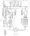
- Fig. 4 shows a system constitution of an examination apparatus according to the invention.
- the same blocks, parts or signals in Fig. 4 as those in Fig.2 are designated by the same reference numerals or numbers as those in Fig. 2 and the description of those will be omitted.
- the computer system 27 in the same manner as in the conventional computer system 56, has a constitution that a processor 28, a memory 29, an output device 30 and input device 31 are connected to a system bus 32. Furthermore, the computer system controls the light source control device 55 so that the light source control device 55 automatically controls the output powers of the light sources LD1 to LD4.
- a transmission light detection device 22 is equipped with a detection controller 23 which controls a detection period of a multi-channel photon-counter 61 and adjusts the gain of a photomultiplier tube 58 by controlling a voltage applied to the photomultiplier tube 58. More specifically, the detection controller 23 controls the detection period of the multi-channel photon-counter 61 according to an instruction from a computer system 22 and also adjusts the voltage applied to the photomultiplier tube 58 according to an amplitude of current which is obtained through photoelectric conversion by the photomultiplier tube 58, amplification by an amplifier 59 and amplitude discrimination by an amplitude discriminator 60. The voltage applied to the photomultiplier tube 58 is adjusted through a control signal CTL'.
- the transmission factor of a filter 24 is set on the basis of the case in which the light quantity of the transmission light is minimum. Therefore, when the light quantity of the transmission light introduced by an optical fiber 53 is small, an prescribed quantity of the transmission light is made incident on the photomultiplier tube 58, a pulse current is outputted from the photomultiplier tube 58, and the detection controller 23 controls the voltage applied to the photomultiplier tube 58 (that is, the gain of the photomultiplier tube) on the basis of the pulse current so that the photomultiplier tube 58 operates with a "photon-counting mode".
- the detection controller 23 controls the gain of the photomultiplier tube 58 on the basis of the analog current so that the photomultiplier tube 58 operates with an "analog detection mode".
- the transmission light detection device 22 of the examination apparatus 21 in Fig. 4 is equipped with the multi-channel photon-counter 61 which is the same as the conventional one and counts in a digital method the number of pulse currents (that is, the number of photons) outputted from the photomultiplier tube 58 when the transmission light quantity incident on the photomultiplier tube 58 is small, and also equipped with an analog detector 25 which detects the analog current outputted from the photomultiplier tube 58 when the transmission light quantity incident on the photomultiplier tube 58 is large.
- the selection of the device for detecting the output current from the photomultiplier tube 58 from the multi-channel photon-counter 61 and the analog detector 25 is made by changing over of switch SW through a selection signal SL.
- the analog detector 25 has a wide dynamic range and the analog current detected by the analog detector 25 is sent to the computer system 27 after being A/D-converted by an A/D converter 26.
- a processor 28, a memory 29, an output device 30 and an input device 31 are connected to a system bus 32 in the same manner as in the conventional computer system 56. Furthermore, the computer system 27 has a function to control the detection controller 23 as described above.
- the transmission factor of the filter 24 is previously set on the basis of the case with the minimum light quantity of the transmission light introduced by the optical fiber 53, the light quantity of the transmission light incident on the photomultiplier tube 58 greatly varies depending on the size of the head 40 or the variation in the absorption quantity by the head 40 with the wavelength. Therefore, it is necessary before the actual oxygenation measurement to initially test whether the transmission light quantity is small and the photomultiplier tube 58 is operating with the photon-counting mode, or the transmission light quantity is large and the photomultiplier tube 58 is operating with the analog detection mode.
- This initial test can be performed in the period M o of the beginning of the examination.
- the near infrared light with the wavelength of ⁇ 1 is emitted from the light source LD1 and the transmission light with the wavelength of ⁇ 1 from the head 40 is made incident on the photomultiplier tube 58 through the filter 24.
- the output current corresponding to the transmission light quantity is outputted from the photomultiplier tube 58 and sent to the detection controller 23.
- the near infrared light rays with the respective wavelengths of ⁇ 2, ⁇ 3 and ⁇ 4 are sequentially emitted from the respective light sources LD2, LD3 and LD4.
- the transmission light rays with the wavelengths of ⁇ 2, ⁇ 3 and ⁇ 4 from the head 40 are sequentially made incident on the photomultiplier tube 58 through the filter 24 in a time-sharing method.
- the output currents corresponding to the respective transmission light quantities are outputted from the photomultiplier tube 58 and sent to the detection controller 23.
- the detection controller 23 judges whether the output currents correspond to the photon-counting mode or the analog detection mode. The result of this judgment is stored in the memory 29 of the computer system 27. The initial setting of the detection modes at every wavelength is completed with the foregoing procedure.
- the detection modes initially set for every wavelength of ⁇ 1 to ⁇ 4 are used in each of the cycles CYl to CYN in the measuring period M k in which the actual oxygenation measurements are performed. That is, at the phase ⁇ n2 in the cycle CYn in the measuring period M k , the detection controller 23 gets the detection mode initially set for the wavelength ⁇ 1 out of the memory 29, adjusts the gain of the photomultiplier tube 58 through the control signal CTL' according to this detection mode, and changes over the switch SW through the selection signal SL.
- the detection controller adjusts the gain of the photomultiplier tube 58 to the value suitable for the photon-counting mode and changes over the switch SW to the multi-channel photon-counter 61.
- the detection controller 23 gets the detection modes initially set for the respective wavelengths ⁇ 2, ⁇ 3 and ⁇ 4 out of the memory 29, adjusts the gain of the photomultiplier tube 58 through the control signal CTL' according to these detection modes, and changes over the switch SW through the selection signal SL.
- the transmission light quantity can be measured with the appropriate detection mode corresponding to the transmission light quantity incident on the photomultiplier tube 58, it is not necessary to cut off the information of the transmission quantity even when the transmission quantity is large and thereby the accurate measurement results can be obtained.
- the detection modes are initially set in the period M o of the beginning of the examination, without performing the initial setting of the detection modes the transmission light quantity may be detected with both detection modes regardless of the magnitude of the transmission light quantity by changing over the photon-counting mode and the analog detection mode within one phase with the time-sharing method.
- two kinds of the transmission quantity data which are detected with the photon-counting mode and the analog detection mode are stored in the memory 29 at the end of the one measuring period M k .
- the processor 28 judges which data are appropriate, selects the appropriate data, and outputs the selected data to the output device 30.
- the number of the light sources is not limited to four, but may be two or more than four.
- the electromagnetic waves with different wavelengths may be obtained by using only one white light source and filtering the white light emitted from the white light source.
- the application of the examination apparatus according to the invention is not limited to the medical field, but covers many fields including mere measurements.
- the measuring object is not limited to body organ, but may be general object such as a piece of flesh.
- the electromagnetic wave emitted from the light source is not limited to the near infrared light, but may be far infrared light, visible light, or microwave.
Description
- The present invention relates to the apparatus for measuring the oxygen concentration in objects such as organs, e.g. the cerebral tissues, of a human body or animals, especially relates to the apparatus for measuring the oxygenation of hemoglobin in blood and that of cytochrome in cells by detecting their effect on electromagnetic radiation.
- In general, in diagnosing the function of the body organ, e.g. the cerebral tissues, it is a fundamental and important parameter whether the oxygen quantity in the body organ is sufficient and it is suitably used. Supplying body organs with sufficient quantity of oxygen is indispensable for the growth ability of foetuses and new-born infants. If the supply of oxygen is insufficient, the death rates of foetuses and new-born infants are high, and even if they live serious problems in body organs may remain as a consequence. The insufficiency of oxygen affects every body organ, especially causes a serious damage in the cerebral tissues.
- To examine the oxygen quantity in body organs readily and at the early stage of illness, an examination apparatus disclosed in US-A-4,281,645 has been developed. In this kind of examination apparatus, the variation of oxygen quantity in body organs, especially in the brain is measured through the absorption spectrum of near infrared light in which the absorption is caused by the hemoglobin which is an oxygen-carrying medium in blood and the cytochrome a, a₃ which performs oxydation-reduction reaction in cells. As shown in Fig. 1(a), the absorption spectra of near infrared light (700 to 1300 nm), αHbO2 and αHb by oxygenated hemoglobin (HbO₂) and disoxygenated hemoglobin (Hb), respectively, are different from each other. And as shown in Fig. 1(b), the absorption spectra of that, αCyO2 and αCy by oxidized cytochrome a, a₃ (CyO₂) and reduced cytochrome a, a₃ (Cy), respectively, are different from each other. This examination apparatus utilizes the above-described absorption spectra of near infrared light. Four near infrared light rays with different wavelengths, λ₁, λ₂, λ₃ and λ₄ (e.g. 775 nm, 800 nm, 825 nm and 850 nm) are applied to one side of the patient's head with a time-sharing method and the transmission light rays from the opposite side of the head are in turn detected. By processing these four detected results with the prescribed calculation program, four unknown quantities, i.e. the density variations of oxygenated hemoglobin (HbO₂), disoxygenated hemoglobin (Hb), oxidized cytochrome a, a₃ (CyO₂) and reduced cytochrome a, a₃ (Cy) are calculated and being based on these parameters, for example the variation of a cerebral oxygen quantity is obtained.
- Fig. 2 shows a system outline of the above-described conventional examination apparatus 45. The conventional examination apparatus 45 includes; light sources such as laser diodes LD1 to LD4 which emit four near infrared light rays with different wavelengths of λ₁, λ₁, λ₃ and λ₄, respectively; a light
source control device 55 which controls output timing of the light sources LD1 to LD4; optical fibers 50-1 to 50-4 which introduces near infrared light rays emitted by the light sources LD1 to LD4 to a patient'shead 40; an illumination-side fixture 51 which bundles and holds end portions of the optical fibers 50-1 to 50-4; a detection-side fixture 52 which is fitted to the prescribed position of the opposite side of the patient'shead 40; aoptical fiber 53 which is held by the detection-side fixture 52 and introduces transmitted near infrared light from the patient'shead 40; a transmissionlight detection device 54 which measures transmission quantity of near infrared light by counting photons of near infrared light introduced by theoptical fiber 53; and acomputer system 56 which controls the total examination apparatus and determines the variation of oxygen quantity in cerebral tissues being based on the transmission quantity of near infrared light. - The
computer system 56 is equipped with aprocessor 62, amemory 63,output devices 64 such as a display and a printer, and an input device 65 such as a keyboard, and these devices are connected each other by asystem bus 66. The lightsource control device 55 and the transmissionlight detection device 54 are connected to thesystem bus 66 as external I/O's. - The light
source control device 55 drives the light sources LD1 to LD4 by respective driving signals ACT1 to ACT4 as shown in Figs. 3(a) to 3(d) according to instructions from thecomputer system 56. As shown in Fig. 3 one measuring period Mk (k = 1, 2, .....) consists of N cycles of CY1 to CYn. At a phase φn1 in an arbitrary cycle CYn, no light source of LD1 to LD4 is driven and therefore the patient'shead 40 is not illuminated by the near infrared light from the light sources LD1 to LD4. At the phase φn2 the light source LD1 is driven and the near infrared light with the wavelength of for example 775 nm is emitted from it. In the same manner, at the phase φn3 the light source LD2 is driven and the near infrared light with the wavelength of for example 800 nm is emitted from it; at the phase φn4 the light source LD3 is driven and the near infrared light with the wavelength of for example 825 nm is emitted from it; and at the phase φn5 the light source LD4 is driven and the near infrared light with the wavelength of for example 850 nm is emitted from it. In this manner the lightsource control device 55 drives the light sources LD1 to LD4 sequentially with a time-sharing method. - The transmission
light detection device 54 is equipped with afilter 57 which adjusts the quantity of near infrared light outputted from theoptical fiber 53;lenses photomultiplier tube 58 which converts the light from thefilter 57 into pulse current and outputs it; anamplifier 59 which amplifies the pulse current from thephotomultiplier tube 58; an amplitude discriminator 60 which eliminates the pulse current from theamplifier 59 whose amplitude is smaller than the prescribed threshold value; a multi-channel photon-counter 61 which detects photon frequency in every channel; for example adetection controller 67 which controls detection periods of the multi-channel photon-counter 61; atemperature controller 68 which controls the temperature of acooler 69 containing thephotomultiplier tube 58. - In use of the above-described examination apparatus, the illumination-side fixture and the detection-side fixture are firmly fitted to the prescribed positions of the patient's
head 40 by using a tape or the like. After that, the light sources LD1 to LD4 are driven by the lightsource control device 55 as shown in Figs. 3(a) to 3(d), respectively, so that the four near infrared light rays with different wavelengths are emitted from the light sources LD1 to LD4 sequentially with the time-sharing method, and the light rays are introduced by the optical fibers 50-1 to 50-4 to the patient'shead 40. As bones and soft tissues in the patient'shead 40 are transparent to the near infrared light, the near infrared light is partially absorbed mainly by hemoglobin in blood and cytochrome a, a₃ in cells and outputted to theoptical fiber 53. And theoptical fiber 53 introduces the light to the transmissionlight detection device 54. At the phase φn1 no light source of LD1 to LD4 is driven, so that the transmissionlight detection device 54 does not receive the transmission light originally emitted from the light sources LD1 to LD4. At this phase the transmissionlight detection device 54 detects dark light. - The
photomultiplier tube 58 in the transmissionlight detection device 54 is the one for photon-counting which has high sensitivity and operates at high response speed. The output pulse current from thephotomultiplier tube 58 is sent to the amplitude discriminator 60 through theamplifier 59. The amplitude discriminator 60 eliminates the noise component whose amplitude is smaller than the prescribed amplitude threshold and sends only the signal pulse to the multi-channel photon-counter 61. The multi-channel photon-counter 61 detects photon number only in the periods T₀ which is made synchronized with the driving signals ACT1 to ACT4 for the respective light sources LD1 to LD4 as shown in Figs. 3(a) to 3(d) by a control signal CTL as shown in Fig. 3(e) from thedetection controller 67, and counts detected photon number of every light with each wavelength sent from theoptical fiber 53. The transmission data of every near infrared light with each wavelength are obtained through the above-described procedure. - That is, as shown in Figs. 3(a) to 3(e), at the phase φn1 in the cycle CYn of light
source control device 55 no light source of LD1 to LD4 is driven, therefore the dark light data d are counted by the transmissionlight detection device 54. At the phases φn2 to φn5 the light sources LD1 to LD4 are sequentially driven with the time-sharing method and the transmissionlight detection device 54 sequentially counts the transmission data tλ1, tλ2, tλ3 and tλ4 of the respective near infrared light rays with different wavelengths λ₁, λ₂, λ₃ and λ₄. - The counting of the dark light data d and the transmission data tλ1, tλ2, tλ3 and tλ4 which is sequentially performed in the cycle CYn, is continued N times from CY1 to CYn. That is, one measuring period Mk (k = 1, 2, .....) includes N cycles. A concrete example is as follows; if one cycle is 200 µsec and N is 10000, the measuring period Mk becomes 2 sec. At the time of finishing of one measuring period Mk, the counting result of the dark light data D

and the counting results of the transmission data Tλ1, Tλ2, Tλ3 and Tλ4
are transferred to thecomputer system 56 and stored in thememory 63. - The
processor 62 performs the subtraction of the dark light component by using the combination of the transmission data and the dark data (Tλ1, Tλ2, Tλ3, Tλ4, D)Mk being stored in thememory 63 after one measuring period Mk and the combination of those (Tλ1, Tλ2, Tλ3, Tλ4, D)M0 at the start of measuring, and calculates the variation rates of the transmission light ΔTλ1, ΔTλ2, ΔTλ3, and ΔTλ4. That is, the variation rates of the transmission light ΔTλ1, ΔTλ2, ΔTλ3 and ΔTλ4 are calculated as:

The use of logarithm in the above calculation of ΔTλj is to express the variation as an optical density. - Using the above-calculated variation rates of the transmission light ΔTλ1, ΔTλ2, ΔTλ3 and ΔTλ4, density variations of oxygenated hemoglobin (HbO₂), disoxygenated hemoglobin (Hb), oxidized cytochrome a, a₃ (CyO₂) and reduced cytochrome a, a₃ which are expressed as ΔXHbO₂ ΔXHb, ΔXCyO₂ and ΔXCy, respectively, can be determined. That is, each of density variations of ΔXHbO₂ ΔXHb, ΔXCyO₂ and ΔXCy is calculated as:

where αij is an absorption coefficient of each component i (HbO₂, Hb, CyO₂, Cy) for each wavelength λj ( λ₁, λ₂, λ₃, λ₄) and is predetermined from Figs. 1(a) and 1(b), and ℓ is the length of the patient'shead 40 along the travelling direction of the near infrared light. - As the above-detected density variation components, ΔXHbO₂, ΔXHb, ΔXCyO₂ and ΔXCy, reflect the variation of oxygen quantity in the brain, the variation of oxygen quantity in the brain can be known by outputting these detected results from the
output device 64 and the diagnosis is made being based on these results. - By the way, the transmission quantity of the near infrared light greatly varies in the order of 10⁴ to 10⁵ with the size of the
head 40, that is, the length ℓ of thehead 40 in the traveling direction of the near infrared light. Even if it is assumed that the size of thehead 40 is kept constant being independent of the patient, as the output powers of the light sources (laser diodes) LD1 to LD4 vary in the order of 10¹ to 10² with their wavelengths of λ₁, λ₂, λ₃ and λ₄ (775 nm, 800 nm, 825 nm and 850 nm, respectively), the transmission quantities also vary sequentially in the order of 10¹ to 10². - On the other hand, it is desired that the light quantity which is made incident on the
photomultiplier tube 58 in the transmissionlight detection device 54 during the measurement should be kept almost constant being independent of the length ℓ of thehead 40 and the variation of the output powers of the light sources LD1 to LD4 with the wavelengths, because the dynamic range of thephotomultiplier tube 58 is approximately in the order of 10². - Therefore, in the conventional examination apparatus 45, a variable light-attenuating ND (Neutral-Density) filter is employed as the
filter 57, whose transmission factor can be manually adjusted. When the examination of one object person is started, the transmission factor of thefilter 57 and each of the output powers of the light sources LD1 to LD4 are manually adjusted so that the incident light quantity on thephotomultiplier tube 58, that is, the transmission light quantity becomes an optimum value. - As described above, the conventional examination apparatus has a problem that because of the manual adjustments of the
filter 57 and the output powers of the light sources LD1 to LD4 it is difficult to adjust the transmission light quantity to the optimum value quickly and accurately. In addition, when the near infrared light transmitted from thehead 40 is too intense the transmission quantity information incident on thephotomultiplier tube 58 is cut off through attenuating the transmission quantity by thefilter 57, which prevents the improvement of the measurement accuracy. - Another problem is that as the transmission factor of the
filter 57 is kept constant after adjustment at the start of measurement, the variation of the transmission factor during the measurement caused by the position change of thefilter 57 cannot be restored. This also prevents the accurate measurement. - According to this invention, an examination apparatus for measuring the oxygenation of an object with electromagnetic radiation transmission spectrophotometry, comprises:
light source means for emitting electromagnetic radiation at a number of different wavelengths;
light source control means for controlling the light source means so as to sequentially emit the electromagnetic radiation;
an illumination-side fixture for contacting the electromagnetic radiation generated by the light source means with an object;
a detection-side fixture for detecting electromagnetic radiation transmitted through the object and sending the transmitted electromagnetic radiation to transmitted light detection means;
the transmitted light detection means detecting the transmitted electromagnetic radiation with a photomultiplier tube and outputting transmission light data; and,
a computer system for controlling the light source control means and the transmission light detection means, and for receiving the transmission light data from the transmission light detection means and calculating the oxygenation in the object;
characterised in that
the transmitted light detection means has two detection modes and detects the transmitted electromagnetic radiation with the appropriate detection mode for the intensity of the transmitted electromagnetic radiation, for each wavelength in the period Mo from the beginning of the examination, and in that the transmitted light detection means further includes a photon-counter and an analogue detector for detecting an output current from the photomultiplier tube; and,
the output current from the photomultiplier tube is detected by the photon-counter in a photon-counting mode when the transmitted light quantity incident on the photomultiplier tube is small, or is detected by the analogue detector in an analogue detection mode when the transmitted light quantity is large wherein appropriate detection modes for the respective electromagnetic radiation of different wavelengths are previously determined at the beginning of the measurement and stored in the computer system. - The present invention provides an examination apparatus which can adjust quickly and accurately to differences in the basic light transmission characteristics of the object and thereby obtains a more accurate measurement result.
- Particular embodiments of examination apparatus in accordance with this invention will now be described with reference to the accompanying drawings; in which:-
- Figures 1(a) and 1(b) are graphs showing the absorption spectra of hemoglobin and cytochrome, respectively;
- Figure 2 is a block diagram of a conventional examination apparatus;
- Figures 3(a) to 3(d) are timing-charts of driving signals ACT1 to ACT4 and a control signal CTL, respectively; and
- Figure 4 is a block diagram of an examination apparatus according to the present invention.
- Fig. 4 shows a system constitution of an examination apparatus according to the invention. The same blocks, parts or signals in Fig. 4 as those in Fig.2 are designated by the same reference numerals or numbers as those in Fig. 2 and the description of those will be omitted.
- The
computer system 27, in the same manner as in theconventional computer system 56, has a constitution that aprocessor 28, amemory 29, anoutput device 30 andinput device 31 are connected to asystem bus 32. Furthermore, the computer system controls the lightsource control device 55 so that the lightsource control device 55 automatically controls the output powers of the light sources LD1 to LD4. - In an examination apparatus 21 in Fig. 4, a transmission
light detection device 22 is equipped with adetection controller 23 which controls a detection period of a multi-channel photon-counter 61 and adjusts the gain of aphotomultiplier tube 58 by controlling a voltage applied to thephotomultiplier tube 58. More specifically, thedetection controller 23 controls the detection period of the multi-channel photon-counter 61 according to an instruction from acomputer system 22 and also adjusts the voltage applied to thephotomultiplier tube 58 according to an amplitude of current which is obtained through photoelectric conversion by thephotomultiplier tube 58, amplification by anamplifier 59 and amplitude discrimination by anamplitude discriminator 60. The voltage applied to thephotomultiplier tube 58 is adjusted through a control signal CTL'. - In this embodiment, the transmission factor of a
filter 24 is set on the basis of the case in which the light quantity of the transmission light is minimum. Therefore, when the light quantity of the transmission light introduced by anoptical fiber 53 is small, an prescribed quantity of the transmission light is made incident on thephotomultiplier tube 58, a pulse current is outputted from thephotomultiplier tube 58, and thedetection controller 23 controls the voltage applied to the photomultiplier tube 58 (that is, the gain of the photomultiplier tube) on the basis of the pulse current so that thephotomultiplier tube 58 operates with a "photon-counting mode". On the other hand, when the light quantity of the transmission light is large, a large quantity of the transmission light is made incident on thephotomultiplier tube 58 and an analog current is outputted from thephotomultiplier tube 58. Thedetection controller 23 controls the gain of thephotomultiplier tube 58 on the basis of the analog current so that thephotomultiplier tube 58 operates with an "analog detection mode". - The transmission
light detection device 22 of the examination apparatus 21 in Fig. 4 is equipped with the multi-channel photon-counter 61 which is the same as the conventional one and counts in a digital method the number of pulse currents (that is, the number of photons) outputted from thephotomultiplier tube 58 when the transmission light quantity incident on thephotomultiplier tube 58 is small, and also equipped with ananalog detector 25 which detects the analog current outputted from thephotomultiplier tube 58 when the transmission light quantity incident on thephotomultiplier tube 58 is large. The selection of the device for detecting the output current from thephotomultiplier tube 58 from the multi-channel photon-counter 61 and theanalog detector 25 is made by changing over of switch SW through a selection signal SL. theanalog detector 25 has a wide dynamic range and the analog current detected by theanalog detector 25 is sent to thecomputer system 27 after being A/D-converted by an A/D converter 26. - In the
computer system 27, aprocessor 28, amemory 29, anoutput device 30 and aninput device 31 are connected to asystem bus 32 in the same manner as in theconventional computer system 56. Furthermore, thecomputer system 27 has a function to control thedetection controller 23 as described above. - In the examination apparatus 21 with the above-described constitution, as the transmission factor of the
filter 24 is previously set on the basis of the case with the minimum light quantity of the transmission light introduced by theoptical fiber 53, the light quantity of the transmission light incident on thephotomultiplier tube 58 greatly varies depending on the size of thehead 40 or the variation in the absorption quantity by thehead 40 with the wavelength. Therefore, it is necessary before the actual oxygenation measurement to initially test whether the transmission light quantity is small and thephotomultiplier tube 58 is operating with the photon-counting mode, or the transmission light quantity is large and thephotomultiplier tube 58 is operating with the analog detection mode. - This initial test can be performed in the period Mo of the beginning of the examination. At the phase φn2 in one cycle CYn in the period Mo, the near infrared light with the wavelength of λ₁ is emitted from the light source LD1 and the transmission light with the wavelength of λ₁ from the
head 40 is made incident on thephotomultiplier tube 58 through thefilter 24. The output current corresponding to the transmission light quantity is outputted from thephotomultiplier tube 58 and sent to thedetection controller 23. - In the same manner, at the phases φn3, φn4 and φn5 in one cycle CYn in the period Mo the near infrared light rays with the respective wavelengths of λ₂, λ₃ and λ₄ are sequentially emitted from the respective light sources LD2, LD3 and LD4. And the transmission light rays with the wavelengths of λ₂, λ₃ and λ₄ from the
head 40 are sequentially made incident on thephotomultiplier tube 58 through thefilter 24 in a time-sharing method. The output currents corresponding to the respective transmission light quantities are outputted from thephotomultiplier tube 58 and sent to thedetection controller 23. In this procedure, on the basis of the output currents at every wavelength outputted over prescribed times of cycles CYl to CYN in the period Mo of the beginning of the examination, thedetection controller 23 judges whether the output currents correspond to the photon-counting mode or the analog detection mode. The result of this judgment is stored in thememory 29 of thecomputer system 27. The initial setting of the detection modes at every wavelength is completed with the foregoing procedure. - The detection modes initially set for every wavelength of λ₁ to λ₄ are used in each of the cycles CYl to CYN in the measuring period Mk in which the actual oxygenation measurements are performed. That is, at the phase φn2 in the cycle CYn in the measuring period Mk, the
detection controller 23 gets the detection mode initially set for the wavelength λ₁ out of thememory 29, adjusts the gain of thephotomultiplier tube 58 through the control signal CTL' according to this detection mode, and changes over the switch SW through the selection signal SL. For example, if the detection mode for the wavelength of λ₁ stored in thememory 29 is the photon-counting mode, the detection controller adjusts the gain of thephotomultiplier tube 58 to the value suitable for the photon-counting mode and changes over the switch SW to the multi-channel photon-counter 61. - At other phases φn3, φn4 and φn5 in the cycle CYn, the
detection controller 23 gets the detection modes initially set for the respective wavelengths λ₂, λ₃ and λ₄ out of thememory 29, adjusts the gain of thephotomultiplier tube 58 through the control signal CTL' according to these detection modes, and changes over the switch SW through the selection signal SL. - As described in the foregoing, as the transmission light quantity can be measured with the appropriate detection mode corresponding to the transmission light quantity incident on the
photomultiplier tube 58, it is not necessary to cut off the information of the transmission quantity even when the transmission quantity is large and thereby the accurate measurement results can be obtained. - Though in the foregoing embodiment the detection modes are initially set in the period Mo of the beginning of the examination, without performing the initial setting of the detection modes the transmission light quantity may be detected with both detection modes regardless of the magnitude of the transmission light quantity by changing over the photon-counting mode and the analog detection mode within one phase with the time-sharing method. In this case, two kinds of the transmission quantity data which are detected with the photon-counting mode and the analog detection mode are stored in the
memory 29 at the end of the one measuring period Mk. Theprocessor 28 judges which data are appropriate, selects the appropriate data, and outputs the selected data to theoutput device 30. - Though the foregoing embodiments are described with four light sources of LD1 to LD4, the number of the light sources is not limited to four, but may be two or more than four.
- Moreover, though the foregoing embodiments are described with plural light sources, the electromagnetic waves with different wavelengths may be obtained by using only one white light source and filtering the white light emitted from the white light source. The application of the examination apparatus according to the invention is not limited to the medical field, but covers many fields including mere measurements. The measuring object is not limited to body organ, but may be general object such as a piece of flesh. Furthermore, the electromagnetic wave emitted from the light source is not limited to the near infrared light, but may be far infrared light, visible light, or microwave.
Claims (4)
- An examination apparatus (21) for measuring the oxygenation of an object with electromagnetic radiation transmission spectrophotometry, comprising:
light source means (LD1-LD4) for emitting electromagnetic radiation at a number of different wavelengths;
light source control means (55) for controlling the light source means (LD1-LD4) so as to sequentially emit the electromagnetic radiation;
an illumination-side fixture (51) for contacting the electromagnetic radiation generated by the light source means (LD1-LD4) with an object (40);
a detection-side fixture (52) for detecting electromagnetic radiation transmitted through the object (40) and sending the transmitted electromagnetic radiation to transmitted light detection means (22);
the transmitted light detection means (22) detecting the transmitted electromagnetic radiation with a photomultiplier tube (58) and outputting transmission light data; and,
a computer system (27) for controlling the light source control means (55) and the transmission light detection means (22), and for receiving the transmission light data from the transmission light detection means (22) and calculating the oxygenation in the object (40);
characterised in that
the transmitted light detection means (22) has two detection modes and detects the transmitted electromagnetic radiation with the appropriate detection mode for the intensity of the transmitted electromagnetic radiation, for each wavelength in the period Mo from the beginning of the examination, and in that the transmitted light detection means (22) further includes a photon-counter (61) and an analogue detector (25) for detecting an output current from the photomultiplier tube (58); and,
the output current from the photomultiplier tube (58) is detected by the photon-counter (61) in a photon-counting mode when the transmitted light quantity incident on the photomultiplier tube (58) is small, or is detected by the analogue detector (25) in an analogue detection mode when the transmitted light quantity is large wherein appropriate detection modes for the respective electromagnetic radiation of different wavelengths are previously determined at the beginning of the measurement and stored in the computer system (27). - An examination apparatus as claimed in claim 1, wherein the transmitted light detection means (22) further includes a detection controller (23) for receiving the output current from the photomultiplier tube (58) and for selecting the detection mode and controlling a voltage applied to the photomultiplier tube (58) in accordance with the received output current.
- An examination apparatus as claimed in claim 1, wherein the computer system (27) controls the transmitted light detection means (22) on the basis of the stored appropriate detection modes so that the detection mode is appropriately selected during the oxygenation measurement.
- An examination apparatus as claimed in any of the preceding claims, wherein the output current from the photomultiplier tube is detected by both the photon-counter (61) and the analogue detector (25) for the electromagnetic radiation of different wavelength, and the computer system (22) selects the appropriate transmission light data from transmission light data obtained in both the photon-counting the analogue detection mode.
Applications Claiming Priority (4)
| Application Number | Priority Date | Filing Date | Title |
|---|---|---|---|
| JP110472/87 | 1987-05-08 | ||
| JP62110472A JPS63277040A (en) | 1987-05-08 | 1987-05-08 | Diagnostic apparatus |
| JP62110465A JPS63275327A (en) | 1987-05-08 | 1987-05-08 | Diagnostic apparatus |
| JP110465/87 | 1987-05-08 |
Publications (2)
| Publication Number | Publication Date |
|---|---|
| EP0290274A1 EP0290274A1 (en) | 1988-11-09 |
| EP0290274B1 true EP0290274B1 (en) | 1993-07-14 |
Family
ID=26450096
Family Applications (1)
| Application Number | Title | Priority Date | Filing Date |
|---|---|---|---|
| EP88304132A Expired - Lifetime EP0290274B1 (en) | 1987-05-08 | 1988-05-06 | Examination apparatus for measuring oxygenation |
Country Status (3)
| Country | Link |
|---|---|
| US (1) | US4907876A (en) |
| EP (1) | EP0290274B1 (en) |
| DE (1) | DE3882273T2 (en) |
Families Citing this family (42)
| Publication number | Priority date | Publication date | Assignee | Title |
|---|---|---|---|---|
| DE3810008C1 (en) * | 1988-03-24 | 1989-10-26 | Johannes Dr. 8000 Muenchen De Buschmann | |
| JPH02257929A (en) * | 1989-03-09 | 1990-10-18 | Makutaa Kk | Instrument for measuring transmissivity through living organism |
| DD298677A5 (en) * | 1989-11-16 | 1992-03-05 | ��������`������������@�������@�������@M�������]k�� | METHOD FOR DETERMINING THE VOLUME FLOW |
| US5902235A (en) * | 1989-03-29 | 1999-05-11 | Somanetics Corporation | Optical cerebral oximeter |
| DE3932421A1 (en) * | 1989-09-28 | 1991-04-11 | Cammann Karl Prof Dr | METHOD AND DEVICE FOR MEASURING ATOMIC SPECTRES FOR DETERMINING THE AMOUNT OF A SEARCHED ELEMENT |
| WO1991018549A1 (en) * | 1990-05-29 | 1991-12-12 | Yue Samuel K | Fetal probe apparatus |
| US5127408A (en) * | 1990-09-14 | 1992-07-07 | Duke University | Apparatus for intravascularly measuring oxidative metabolism in body organs and tissues |
| US5349952A (en) * | 1991-03-05 | 1994-09-27 | Sensormedics Corp. | Photoplethysmographics using phase-division multiplexing |
| WO1992021283A1 (en) * | 1991-06-06 | 1992-12-10 | Somanetics Corporation | Optical cerebral oximeter |
| EP0549835B1 (en) * | 1991-12-30 | 1996-03-13 | Hamamatsu Photonics K.K. | Diagnostic apparatus |
| US5308919A (en) * | 1992-04-27 | 1994-05-03 | Minnich Thomas E | Method and apparatus for monitoring the arteriovenous oxygen difference from the ocular fundus |
| EP0615723A1 (en) * | 1993-03-04 | 1994-09-21 | Hamamatsu Photonics K.K. | Method and apparatus for measuring blood flow |
| US5715326A (en) * | 1994-09-08 | 1998-02-03 | Neopath, Inc. | Cytological system illumination integrity checking apparatus and method |
| US5879294A (en) * | 1996-06-28 | 1999-03-09 | Hutchinson Technology Inc. | Tissue chromophore measurement system |
| US5935076A (en) * | 1997-02-10 | 1999-08-10 | University Of Alabama In Huntsville | Method and apparatus for accurately measuring the transmittance of blood within a retinal vessel |
| US5776060A (en) * | 1997-02-20 | 1998-07-07 | University Of Alabama In Huntsville | Method and apparatus for measuring blood oxygen saturation within a retinal vessel with light having several selected wavelengths |
| US5891024A (en) * | 1997-04-09 | 1999-04-06 | Ohmeda Inc. | Two stage calibration and analyte measurement scheme for spectrophotomeric analysis |
| US7047054B2 (en) | 1999-03-12 | 2006-05-16 | Cas Medical Systems, Inc. | Laser diode optical transducer assembly for non-invasive spectrophotometric blood oxygenation monitoring |
| US6456862B2 (en) | 2000-05-02 | 2002-09-24 | Cas Medical Systems, Inc. | Method for non-invasive spectrophotometric blood oxygenation monitoring |
| WO2001082786A2 (en) * | 2000-05-03 | 2001-11-08 | Flock Stephen T | Optical imaging of subsurface anatomical structures and biomolecules |
| AU2003254135B2 (en) | 2002-07-26 | 2006-11-16 | Cas Medical Systems, Inc. | Method for spectrophotometric blood oxygenation monitoring |
| US7196783B2 (en) | 2002-11-15 | 2007-03-27 | Accurate Machining, Inc. | Optical fiber bundle utilizing electromagnetic radiation feedback |
| WO2004088289A1 (en) * | 2003-04-01 | 2004-10-14 | Siemens Aktiengesellschaft | Process absorption spectrometer |
| EP1682002A4 (en) * | 2003-10-15 | 2010-03-31 | Univ British Columbia | Methods and apparatus for urodynamic analysis |
| US8260389B2 (en) * | 2003-10-15 | 2012-09-04 | Hegln (Dalian) Pharmaceuticals, Inc. | Bladder function monitoring methods, apparatuses, media and signals |
| KR100634498B1 (en) * | 2004-01-12 | 2006-10-13 | 삼성전자주식회사 | Apparatus and method for measuring constituents of body |
| US8190223B2 (en) | 2005-03-01 | 2012-05-29 | Masimo Laboratories, Inc. | Noninvasive multi-parameter patient monitor |
| US7937129B2 (en) * | 2005-03-21 | 2011-05-03 | Masimo Corporation | Variable aperture sensor |
| EP1885235B1 (en) * | 2005-05-12 | 2013-12-18 | Cas Medical Systems, Inc. | Improved method for spectrophotometric blood oxygenation monitoring |
| CA2614968A1 (en) * | 2005-07-11 | 2007-01-18 | Simon Fraser University | Method and apparatus for venipuncture site location |
| WO2008118993A1 (en) | 2007-03-27 | 2008-10-02 | Masimo Laboratories, Inc. | Multiple wavelength optical sensor |
| US8374665B2 (en) | 2007-04-21 | 2013-02-12 | Cercacor Laboratories, Inc. | Tissue profile wellness monitor |
| US8391942B2 (en) * | 2008-10-06 | 2013-03-05 | Cas Medical Systems, Inc. | Method and apparatus for determining cerebral desaturation in patients undergoing deep hypothermic circulatory arrest |
| US20100105998A1 (en) * | 2008-10-28 | 2010-04-29 | Cas Medical Systems, Inc. | Method and apparatus for spectrophotometric based oximetry of spinal tissue |
| US9839381B1 (en) | 2009-11-24 | 2017-12-12 | Cercacor Laboratories, Inc. | Physiological measurement system with automatic wavelength adjustment |
| DE112010004682T5 (en) | 2009-12-04 | 2013-03-28 | Masimo Corporation | Calibration for multi-level physiological monitors |
| US9775545B2 (en) | 2010-09-28 | 2017-10-03 | Masimo Corporation | Magnetic electrical connector for patient monitors |
| JP5710767B2 (en) | 2010-09-28 | 2015-04-30 | マシモ コーポレイション | Depth of consciousness monitor including oximeter |
| US20120184831A1 (en) * | 2011-01-18 | 2012-07-19 | Radiation Monitoring Devices, Inc. | Systems, devices and methods for monitoring hemodynamics |
| US9848808B2 (en) | 2013-07-18 | 2017-12-26 | Cas Medical Systems, Inc. | Method for spectrophotometric blood oxygenation monitoring |
| WO2016057553A1 (en) | 2014-10-07 | 2016-04-14 | Masimo Corporation | Modular physiological sensors |
| CN113777058A (en) * | 2021-09-09 | 2021-12-10 | 武汉爱可泰思医疗科技有限公司 | Human brain dynamic body-simulating device and near-infrared optical instrument accuracy calibration method |
Family Cites Families (7)
| Publication number | Priority date | Publication date | Assignee | Title |
|---|---|---|---|---|
| US3794425A (en) * | 1972-08-22 | 1974-02-26 | Shell Oil Co | Scanning infrared spectroscopic analyzer using rotating variable filter |
| US3905706A (en) * | 1973-12-17 | 1975-09-16 | Us Navy | Light responsive bathyirradiometer |
| US4158505A (en) * | 1976-12-27 | 1979-06-19 | International Business Machines Corporation | Spectrum analyzing system with photodiode array |
| US4281645A (en) * | 1977-06-28 | 1981-08-04 | Duke University, Inc. | Method and apparatus for monitoring metabolism in body organs |
| AU8706982A (en) * | 1981-09-17 | 1983-05-12 | Miles Laboratories Inc. | Spectrophotometer for analytic and diagnostic purposes |
| EP0102816A3 (en) * | 1982-09-02 | 1985-08-28 | Nellcor Incorporated | Pulse oximeter |
| CH665026A5 (en) * | 1983-07-15 | 1988-04-15 | Ritzl Hermann | SPECTROMETER. |
-
1988
- 1988-05-02 US US07/188,957 patent/US4907876A/en not_active Expired - Fee Related
- 1988-05-06 DE DE88304132T patent/DE3882273T2/en not_active Expired - Fee Related
- 1988-05-06 EP EP88304132A patent/EP0290274B1/en not_active Expired - Lifetime
Also Published As
| Publication number | Publication date |
|---|---|
| EP0290274A1 (en) | 1988-11-09 |
| US4907876A (en) | 1990-03-13 |
| DE3882273T2 (en) | 1993-10-21 |
| DE3882273D1 (en) | 1993-08-19 |
Similar Documents
| Publication | Publication Date | Title |
|---|---|---|
| EP0290274B1 (en) | Examination apparatus for measuring oxygenation | |
| EP0290279B1 (en) | Examination apparatus for measuring oxygenation | |
| EP0290272B1 (en) | Examination apparatus for measuring oxygenation | |
| EP0525107B1 (en) | Method and apparatus for measuring the concentration of absorbing substances | |
| US6018674A (en) | Fast-turnoff photodiodes with switched-gain preamplifiers in photoplethysmographic measurement instruments | |
| US4407290A (en) | Blood constituent measuring device and method | |
| US4942877A (en) | Device for measuring oxygen saturation degree in arterial blood | |
| US5253646A (en) | Diagnostic apparatus for measuring changes of arterial and venous blood volumes in brain with respiration signal modulation | |
| US5088493A (en) | Multiple wavelength light photometer for non-invasive monitoring | |
| US4114604A (en) | Catheter oximeter apparatus and method | |
| EP0497021A1 (en) | Oximeter with monitor | |
| EP0329115B1 (en) | Tissue metabolism measuring apparatus | |
| EP0290275B1 (en) | Examination apparatus for measuring oxygenation | |
| JPS63275325A (en) | Diagnostic apparatus | |
| EP0290273A1 (en) | Examination apparatus for measuring oxygenation | |
| EP0290278A1 (en) | Examination apparatus for measuring oxygenation | |
| EP1690495B1 (en) | Biological photometric equipment | |
| RU2040912C1 (en) | Optical method and device for determining blood oxygenation | |
| JPS63275327A (en) | Diagnostic apparatus | |
| JP3524976B2 (en) | Concentration measuring device | |
| KR900000843B1 (en) | Tissue metabolism measuring apparatus | |
| JP2000300569A (en) | Biological light measuring instrument | |
| JP2807272B2 (en) | Diagnostic device by light | |
| JPS63277040A (en) | Diagnostic apparatus | |
| JPH06181930A (en) | Organismic light measuring device |
Legal Events
| Date | Code | Title | Description |
|---|---|---|---|
| PUAI | Public reference made under article 153(3) epc to a published international application that has entered the european phase |
Free format text: ORIGINAL CODE: 0009012 |
|
| AK | Designated contracting states |
Kind code of ref document: A1 Designated state(s): DE GB |
|
| 17P | Request for examination filed |
Effective date: 19890420 |
|
| 17Q | First examination report despatched |
Effective date: 19920120 |
|
| GRAA | (expected) grant |
Free format text: ORIGINAL CODE: 0009210 |
|
| AK | Designated contracting states |
Kind code of ref document: B1 Designated state(s): DE GB |
|
| REF | Corresponds to: |
Ref document number: 3882273 Country of ref document: DE Date of ref document: 19930819 |
|
| PLBE | No opposition filed within time limit |
Free format text: ORIGINAL CODE: 0009261 |
|
| STAA | Information on the status of an ep patent application or granted ep patent |
Free format text: STATUS: NO OPPOSITION FILED WITHIN TIME LIMIT |
|
| 26N | No opposition filed | ||
| PGFP | Annual fee paid to national office [announced via postgrant information from national office to epo] |
Ref country code: DE Payment date: 20000502 Year of fee payment: 13 |
|
| PGFP | Annual fee paid to national office [announced via postgrant information from national office to epo] |
Ref country code: GB Payment date: 20000503 Year of fee payment: 13 |
|
| PG25 | Lapsed in a contracting state [announced via postgrant information from national office to epo] |
Ref country code: GB Free format text: LAPSE BECAUSE OF NON-PAYMENT OF DUE FEES Effective date: 20010506 |
|
| GBPC | Gb: european patent ceased through non-payment of renewal fee |
Effective date: 20010506 |
|
| PG25 | Lapsed in a contracting state [announced via postgrant information from national office to epo] |
Ref country code: DE Free format text: LAPSE BECAUSE OF NON-PAYMENT OF DUE FEES Effective date: 20020301 |