EP0293226A1 - Apparatus for inspecting glass bottles - Google Patents
Apparatus for inspecting glass bottles Download PDFInfo
- Publication number
- EP0293226A1 EP0293226A1 EP88304834A EP88304834A EP0293226A1 EP 0293226 A1 EP0293226 A1 EP 0293226A1 EP 88304834 A EP88304834 A EP 88304834A EP 88304834 A EP88304834 A EP 88304834A EP 0293226 A1 EP0293226 A1 EP 0293226A1
- Authority
- EP
- European Patent Office
- Prior art keywords
- measuring
- bottle
- bottles
- station
- inspecting
- Prior art date
- Legal status (The legal status is an assumption and is not a legal conclusion. Google has not performed a legal analysis and makes no representation as to the accuracy of the status listed.)
- Granted
Links
Images

Classifications
-
- G—PHYSICS
- G01—MEASURING; TESTING
- G01B—MEASURING LENGTH, THICKNESS OR SIMILAR LINEAR DIMENSIONS; MEASURING ANGLES; MEASURING AREAS; MEASURING IRREGULARITIES OF SURFACES OR CONTOURS
- G01B5/00—Measuring arrangements characterised by the use of mechanical techniques
- G01B5/24—Measuring arrangements characterised by the use of mechanical techniques for measuring angles or tapers; for testing the alignment of axes
-
- B—PERFORMING OPERATIONS; TRANSPORTING
- B07—SEPARATING SOLIDS FROM SOLIDS; SORTING
- B07C—POSTAL SORTING; SORTING INDIVIDUAL ARTICLES, OR BULK MATERIAL FIT TO BE SORTED PIECE-MEAL, e.g. BY PICKING
- B07C5/00—Sorting according to a characteristic or feature of the articles or material being sorted, e.g. by control effected by devices which detect or measure such characteristic or feature; Sorting by manually actuated devices, e.g. switches
- B07C5/04—Sorting according to size
- B07C5/12—Sorting according to size characterised by the application to particular articles, not otherwise provided for
- B07C5/122—Sorting according to size characterised by the application to particular articles, not otherwise provided for for bottles, ampoules, jars and other glassware
- B07C5/124—Sorting according to size characterised by the application to particular articles, not otherwise provided for for bottles, ampoules, jars and other glassware by means of mechanical measuring devices which may also control electrical contacts
-
- B—PERFORMING OPERATIONS; TRANSPORTING
- B07—SEPARATING SOLIDS FROM SOLIDS; SORTING
- B07C—POSTAL SORTING; SORTING INDIVIDUAL ARTICLES, OR BULK MATERIAL FIT TO BE SORTED PIECE-MEAL, e.g. BY PICKING
- B07C5/00—Sorting according to a characteristic or feature of the articles or material being sorted, e.g. by control effected by devices which detect or measure such characteristic or feature; Sorting by manually actuated devices, e.g. switches
- B07C5/34—Sorting according to other particular properties
-
- B—PERFORMING OPERATIONS; TRANSPORTING
- B07—SEPARATING SOLIDS FROM SOLIDS; SORTING
- B07C—POSTAL SORTING; SORTING INDIVIDUAL ARTICLES, OR BULK MATERIAL FIT TO BE SORTED PIECE-MEAL, e.g. BY PICKING
- B07C5/00—Sorting according to a characteristic or feature of the articles or material being sorted, e.g. by control effected by devices which detect or measure such characteristic or feature; Sorting by manually actuated devices, e.g. switches
- B07C5/36—Sorting apparatus characterised by the means used for distribution
-
- G—PHYSICS
- G01—MEASURING; TESTING
- G01B—MEASURING LENGTH, THICKNESS OR SIMILAR LINEAR DIMENSIONS; MEASURING ANGLES; MEASURING AREAS; MEASURING IRREGULARITIES OF SURFACES OR CONTOURS
- G01B5/00—Measuring arrangements characterised by the use of mechanical techniques
- G01B5/08—Measuring arrangements characterised by the use of mechanical techniques for measuring diameters
Definitions
- This invention relates to an apparatus for inspecting glass bottles, and more particularly to an apparatus for inspecting a glass bottles capable of automatically measuring various portions of each glass bottle such as the weight thereof, inclination of the sealing surface of the top lip opening, outer diameter of the shell or barrel portion, perpendicularity thereof, outer and inner diameters of the top lip opening and the like in a sequential measuring process by means of a plurality of inspecting devices located circumferentially of an inspecting table.
- the inclination of the top surface of the lip opening of a glass bottle relative to the reference surface of the bottom of the glass bottle is generally called down sealing surface
- the down sealing surface has been measured in a conventional technique by abutting the contact of a dial gauge against the top portion of the lip opening to measure distances from the reference surface to the top surface at a plurality of portions of the glass bottle while rotating the glass bottle placed on a rotary measuring table about the vertical axis of the bottle, and by comparing the measured distances, whereby the down sealing surface is calculated.
- the top surface of the lip opening portion of a glass bottle often has minutely waved portions formed during the manufacturing process, and accordingly, in the conventional measuring method by using a dial gauge, it has not been expected to exactly measure the down sealing surface because of the existence of the waved portions formed on the top surface of the glass bottle.
- this conventional measuring technique since the glass bottles are periodically sampled during the manufacturing process for randomly measuring the dimensions of the glass bottle such as the lip portion, the neck portion, the barrel portion and the bottom portion and measured or inspected by means of a vernier caliper or other measuring gauges, this conventional measuring technique also gives rise to problems of the measuring accuracy, the measuring efficiency or the like, which result in deficient quality control.
- an object of this invention is to substantially eliminate the difficulties or problems encountered in the conventional technique described above and to provide an apparatus for inspecting glass bottles in order to obtain glass bottles having superior quality.
- Another object of this invention is to provide an apparatus for inspecting glass bottles in a sequential manner with a plurality of stations for inspecting or measuring the down sealing surface of each glass bottle, outer diameters of various portions thereof, perpendicularlity thereof, the inner diameter of the lip opening thereof, and the like.
- a further object of this invention is to provide an apparatus for inspecting glass bottles capable of automatically performing various inspections and measurements simultaneously at respective stations.
- an apparatus for inspecting glass bottles comprising an operation table, an annular conveyer which is mounted on the operation table and on which bottles to be inspected are mounted in slidable manner, an annular turn table coaxially disposed inside the annular conveyer and provided with a plurality of guide members circumferentially disposed on the peripheral surface of the turn table, a take-in conveyer operatively connected to the annular conveyer for introducing bottles to be inspected one by one thereinto, a take-out conveyer operatively connected to the annular conveyer for discharging the bottles inspected one by one therefrom, and a plurality of inspecting stations arranged with equal spacing in the circumferential direction around the outer peripheral surface of the annular conveyer, the inspecting stations including a down sealing surface measuring station, an outer diameter measuring station, and an inner diameter and perpendicularity measuring station.
- the glass bottles are conveyed one-by-one intermittently on the annular conveyer and stopped at every inspecting station arranged in an equally spaced manner, so that the various measurements or inspections of the respective portions of the glass bottles can be automatically simultaneously performed.
- a control chart can be easily prepared on the basis of the data from the respective stations, thereby being capable of carrying out the highly graded quality control of the bottles manufactured.
- the down sealing surface measuring station is equipped with an improved measuring device which includes a measuring plate having a flat surface to be forcibly contacted with the top surface of the lip portion of a bottle to be inspected.
- the down sealing surface of the lip top portion of the bottle can be measured precisely by measuring the vertical distances of predetermined portions of the lip top portion from the reference surface by means of linear gauges arranged on the circumferential portions of a circle having a diameter larger than that of the lip opening.
- the outer diameter measuring station is equipped with a device having a linear gauge to measure the outer diameters of various portions of the bottle to be inspected.
- the linear gauge for measuring the diameter of the lower lip portion is supported by a resilient member to be vertically movable so that the measuring probe of the linear gauge can abut positively against the lower lip portion to be measured.
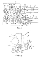
- FIG. 1 is a plan view of a glass bottle inspecting apparatus according to this invention
- an annular conveying passage 2 is stationarily secured to an operation table 1
- a turn table 5 is coaxially disposed inside the annular conveying passage 2 to be rotatable in the clockwise direction as viewed in FIG. 1 from above about a central shaft 3.
- a plurality of guide pushers 6, six in the illustrated example, are mounted at equally spaced intervals on the outer peripheral surface of the turn table 5.
- the guide pushers 6 are secured to the turn table 5 in a floating manner with a slight space and provided with recesses 6a in their front surfaces, respectively, with respect to the rotating direction of the turn table 5, each of the recesses 6a having a shape suitable for receiving the barrel portions of a respective glass bottle 8 conveyed on the conveying passage 2.
- the glass bottle 8 is then pushed by the guide pusher 6 to be slidably moved on the conveying passage 2 in the clockwise direction.
- a plurality of inspecting stations are disposed on the operation. table 1 around the outer peripheral portion of the conveying passage 2, the inspecting stations being equipped with various respective devices or equipment for inspecting or measuring the various portions of each glass bottle.
- the six inspecting stations comprise a first station A for measuring the weight of each glass bottle 8, a second station B for measuring the bottom rising, the down sealing surface and the overall height of the glass bottle 8, a third station C for measuring the barrel diameter, the outer diameter of the lip portion, and the perpendicularity of the glass bottle, a fourth station D for measuring the inner diameter of the lip opening, a fifth empty station E provided as a spare, and a sixth station F for discriminating the respective code or reference numbers of the respective glass bottles 8.
- the details of the respective stations A to F will be described hereinafter.
- a take-in conveyer 10 for taking each glass bottle 8 to be inspected into the conveying passage 2 is operatively connected to the inlet side of the weight measuring station A and a take-out conveyer 11 for taking out each inspected glass bottle 8 is connected to the outlet side of the code number designating station F .
- the take-in conveyer 10 in belt form, is equipped with guide members 12 at both sides and a conveyer passage 13 formed between the guide members 12, both extending in the longitudinal direction of the take-in conveyer 10.
- the conveyer passage 13 is reduced in width towards the operation table 1 and has a narrowest portion 13A enabling only one glass bottle 8 to pass, and two piston-cylinder assemblies 14 and 15 are supported in parallel to each other on portions of the guide member 12 corresponding to the narrowest portion 13a of the conveyer passage 13.
- the piston-cylinder assemblies 14 and 15 are equipped at their respective front ends with stop members 14a and 15a so as to be freely advanced into or retracted from the conveyer passage 13.
- a sensor, not shown, for detecting the arrival of each bottle 8 at the outlet portion of the passage 13 is disposed at a portion denoted by the reference character G.
- the stop members 14a and 15a define a space therebetween having a longitudinal distance suitable for substantially accommodating one bottle 8.
- the stop members 14a and 15a are so operated that when the stop member 14a is retracted, the bottle 8 is conveyed to the portion G, when the stop member 14a is advanced and the stop member 15a is retracted, the bottle 8 is received in the space defined therebetween, and when the stop member 15a is advanced, the entrance of the next bottle 8 on the passage 13 on the upstreamside thereof is prevented, whereby the bottles 8 can be positively and precisely conveyed to the portion G one by one.
- a transfer piston-cylinder assembly 18 is disposed on the operation table 1 at a portion between the station A and the portion G and has a piston rod 18a to the front end of which is secured a transfer claw member 19 which operates to transfer the bottle 8 from the portion G to the station A in accordance with the retraction of the piston rod 18a.
- a weighing device not shown, connected to a load cell supporting the glass bottle 8 in a float-off condition is provided on the conveying passage 2 of the weight measuring station A so as to measure the weight of the bottle 8 placed on the weighing device.
- the bottle is then transferred to the second station B for measuring. the down sealing surface of the lip portion thereof.
- This transfer is performed by rotating the turn table 5 about the central shaft 3 thereof by controlling an electric drive motor, not shown, so that the turn table is intermittently rotated by angular increments each of 60 degrees in the illustrated example.
- the rotation angles may be set to, for example 45° or 30°, in accordance with the number of stations.
- FIG. 2 is a plan view showing a mechanism for intermittently stopping the rotation of the turn table 5, in which a sensor mounting plate 20 is positioned on the operation table 1 at one portion thereof along the outer periphery of the conveying passage 2, and a pair of sensors 21 and 22 are disposed on the sensor mounting 20, while all guide members 6 are provided with protruding portions 23 respectively at end portions thereof on the side opposed to the sensors 21 and 22.
- the sensor mounting plate 20 is adapted to be circumferentially movable, and the circumferential displacement is measured by means of a micro-gauge 24.
- the sensor 21 detects the approaching of the guide member 6 and operates to reduce the rotating speed of the turn table 5 to finally stop the guide member 6 when this guide member approaches the other sensor 22 as shown by solid lines precisely at a position corresponding to the sensor 22.
- the turn table 5 is reversely rotated to a position at which the protruding portion 23 corresponds to the first mentioned sensor 21 for the various other measuring processes described hereinlater.
- the guide member 6 is returned to a position corresponding to the sensor 21, whereas the glass bottle 8 to be inspected remains on the conveying passage 2 at a portion shown by two-dot and dash line in FIG. 2, and accordingly, in the case where six stations A to F are disposed as in this example. six bottles 8 remain as shown on the conveying passage with respect to the respective guide members 6.
- the micro-gauge 24 is utilized for minute adjustment of the stopping position, and in fact, when the barrel diameters of the respective bottles 8 are different from each other, the minute adjustment is performed by the micro-gauge 24. Therefore, according to the apparatus of this invention, the glass bottles 8 can be stopped exactly at predetermined of the respective stations A to E only by stopping the turn table 5 exactly at one part corresponding to one station.
- a down sealing surface measuring device 25 is mounted at a part of the down sealing surface measuring station B at which the bottom rising of the bottle 8 is simultaneously measured or inspected.
- a support column 26 stands vertically on the operation table 1, and a support stand 27 is supported as a cantilever by the upper part of the support column 26 in parallel to the table 1.
- a mounting device 28 comprising leg parts 28a and an attachment plate 28b is mounted on the upper surface of the support stand 27.
- a piston-cylinder assembly 29 provided with a piston rod 29a having an outer end by which a measuring plate 31 is supported by way of a rod 30.
- a small gap 30a is defined by a connecting space between the measuring plate 31 and the rod 30 to allow free inclination of the plate 31, and a coil spring 32 having an outer diameter larger than the inner diameter of the lip opening of the bottle 8 is interposed between the measuring plate 31 and the lower surface of the support stand 27.
- Three linear gauge means 33 are mounted on the support stand 27 in an arrangement schematically indicated in FIG. 5, in which the front probing ends of the linear gauges 33A, 33B and 33C. constitute the apexes of a equilateral triangle.
- the measuring probe 33A of the linear gauge 33a for example, is urged downwardly so as to abut against the upper surface 31a of the measuring plate 31.
- a gauge means as a linear gauge in which a linear displacement can be taken out as an output of a differential transferring device in which a core of a probe is moved in a coil is utilized.
- the down sealing surface K is calculated as follows: in which: m1, m2 and m3 are values measured by the gauges 33A, 33B and 33C, respectivley; the letter r denotes the radius of the circumscribing circle of the triangle shown in FIG. 5; and the letter D denotes the outer diameter of the lip opening of the bottle being inspected.
- the down sealing surface K can be thus calculated by substituting the measured values of the linear gauges 33 into the equation (1) and can be easily and speedily obtained by storing the operating equation (1) in a computer, for example.
- the overall bottle height T shown in FIG. 3, can be calculated by substituting the measured values m1, m2 and m3 into the following equation (2).
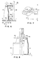
- FIG. 6 is a side view of the diameter measuring device 34, in which a stand 35 is mounted on the operation table 1 in a vertically extending manner.
- a plurality of, five in the illustrated embodiment, sensors 36 (36A, 36B, 36C, 36D and 36E) for detecting and measuring outer diameters of respective portions of the bottle are mounted on the vertical stand 35 in a vertically separated arrangement.
- the sensors 36A, 36B, 36C, 36D and 36E respectively detect and measure the diameter of the upper lip portion, the diameter of the lower lip portion, the diameter of a swoller portion of the lower lip, the diameter of the barrel portion, and the diameter of the lowermost bottom portion of the bottle 8.
- the glass bottle 8 to be inspected is placed on an annular rotating plate 38, and the bottom of the bottle 8 can be stationarily held by means of a sucking device 40 provided with a sucking head 39. That is, as shown in FIG. 6, since the bottom portion 8b of the glass bottle 8 is downwardly sucked by means of the sucking head 39, the bottle 8 is rotated with the circumferential surface of the bottom portion 8b pressed downwardly against the annular rotating plate 38. As described above, since the bottle 8 is forcibly sucked downwardly, there is no need for positioning an extra mechanism for supporting the bottle on the side thereof.
- the principle of measuring the outer diameter of the glass bottle will be described hereunder with reference to FIG. 7, in which it is prescribed that the rotational axis O of the rotary measuring table 38 is spacedfrom a reference axis X-X by a distance D, and the glass bottle 8 to be inspected is placed on the measuring table 38 at a position offset by a distance ⁇ from the center of the measuring table 38.
- the characters m i and m i+ ⁇ represent the measured values at positions at times when the glass bottle 8 is counterclockwisely rotated by the circumferential angles of ⁇ and ⁇ + ⁇ from the reference line P.
- the outer diameter at any portion of the bottle can be calculated on the basis of the equation (6) by detecting the distances m i and m i+ ⁇ from the reference axis of the circumferential two points on the diameter at an optional part of the glass bottle.
- the values m i and m i+ ⁇ can be measured by means of a linear gauge, the outer diameter at the desired portion of the glass bottle being thus measured, according to the principle described with reference to FIG. 7.
- the sensors 36A and 36B for measuring the outer diameters of the upper and lower lip portions of the glass bottle 8 are fixed to predetermined parts of the vertical stand 35.
- the measurement of the overall height of the glass bottle ordinarily includes a measurement error caused in the manufacturing process thereof, and accordingly, the vertical height of the lip portion is not always uniform.
- the sensors for measuring the diameter of the lower lip portion of the bottle 8 in a position suitable for always correctly measuring the same lip portions of the bottles to be measured.
- FIG. 8 shows one device according to this invention for satisfying this requirement, in which the diameter measuring sensor is resiliently suspended in a manner described hereunder.
- a support column 40 is vertically mounted on the operation table 1 and is provided with a guide rail 41 extending vertically, along which a slider 42 is mounted to be vertically slidable.
- a diameter measuring means such as a pneumatically operated micrometer 43 disposed in a horizontal plane and having a measuring element 43a of a short column shape suitable for measuring the outer diameters of the lower lip portions of the glass bottle 8.
- the pneumatic micrometer 43 is suspended by a fixing plate 45 through a resilient member such as a coil spring 44.
- the perpendicularity is measured by calculating outputs from a lip diameter sensor (36A) and a bottom portion sensor (36E).
- a lip diameter sensor 36A
- a bottom portion sensor 36E
- the outer circumference of a bottle is divided in 100 sections, determining central coordinates of the lip and those of the bottom portion, at each 100 point, determining the absolute values of the differences between the central coordinates at the 100 points, and using the largest one of the absolute values as a perpendicularity.
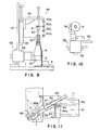
- the station D for measuring the inner diameter of the lip opening of the glass bottle 8 has a structure described hereunder with reference to FIG. 9.
- a device 46 for measuring the inner diameter of the lip opening of the glass bottle 8 is provided at the station D and is supported by a movable plate 49 to be vertically movable.
- the movable plate 49 is also supported by a vertical column 47 standing vertically on the upper surface of the operation table 1 to be vertically movable through a cylinder assembly 48.
- the measuring device 46 comprises a gauge rod 50 supported by the movable plate 49 through a floating member 51 so as to extend in a direction, perpendicular thereto and three ball gauges 52 coaxially mounted on the gauge rod 50 in a vertically separated state, the uppermost ball gauge having a diameter slightly larger than that of the intermediate ball gauge, which has a diameter slightly larger than that of the lowermost ball gauge.
- the inner diameter of the lip opening of the bottle 8 can be accordingly measured by inserting the ball gauges 52 in the manner of limit gauges and sensing the state of passage of the ball gauges through the lip opening by means of sensors 53 (53a through 53d).
- the glass bottle 8 is stationarily held by a bottle holding mechanism 54 which holds the barrel portion of the glass bottle 8.
- the bottle holding mechanism 54 comprises a bottle holding claw 56 and a cylinder assembly 55 adapted to open or close the claw 56. Accordingly, the insertion of the ball gauges 52 into the lip opening of the bottle 8 can be carried out smoothly without accidentally toppling down the glass bottle 8.
- the various values or data measured at the respective stations are transferred together with the reference numbers of the glass bottles inspected or measured into a control box, not shown, and the controlled data is then transferred into a computer, in which mold cavity numbers of glass bottle molding machines are preliminarily stored.
- Data concerning the respective mold cavities can thus be regulated or adjusted on the basis of the data from the control box and displayed as a control chart. Accordingly, the occurrence of a detective glass bottle as a product can be easily discriminated by viewing the control chart, based on which quick action against further occurrence of the defective product can be promptly taken.
- the respective dimensions of the various portions of the glass bottles to be continuously inspected have tendency to gradually increase or decrease with respect to the prescribed standard values, and according to this tendency, quick action can be taken for manufacturing glass bottles having substantially the same dimensions or sizes, whereby quality control of the glass bottles to be manufactured as products can be precisely and quickly performed.
- FIG. 11 is a plan view of a take-out conveyer 11 operatively sequentially connected to the reference number discriminating station F .
- the take-out conveyer 11 comprises an defective product conveyer 60 and a non-defective or satisfactory product conveyer 61.
- a director plate 63 is swingably supported on a pivot shaft 62 at the entrance of the conveyers 60 and 61.
- a base end part of the director plate 63 is coupled to the outer end of a piston rod 64a of a swingable piston-cylinder assembly 64 secured to the operation table 1 so that the free end, i.e., the distal end, of the director plate 63 can be projected into a guide passage 67 defined by a pair of guide plates 65 and 66.
- a discharge piston-cylinder assembly 69 is installed above the guide passage 67 and provided with a member 68 movable along the passage 67.
- This discharge piston-cylinder assembly 69 has a piston rod 69a.
- the glass bottles 8 after being inspected or measured are directed to the entrances of the conveyors 60 and 61 from the station F in accordance with the quality of the inspected bottles.
- the director plate 63 is projected into the guide passage 67 by the action of the swingable piston-cylinder assembly 64, the glass bottles are conveyed onto the satisfactory product conveyer 61, whereas the glass bottles are conveyed into the defective product conveyer when the direction plate 63 is retracted from the guide passage 67.
- the actuation of the swingable piston-cylinder assembly 64 may be controlled manually or in response to a control signal from the computer, whereby the discharge or recovery of the defective products can be easily made.
- the defective glass bottles will be discharged in the order in which they are measured by constructing the directing and conveying mechanism so that only one bottle can rest on the defective product conveyer 60. Then, according to this, arrangement, the discharged defective glass bottles and the data obtained by the control box can be easily referred to correspondingly to each other even if the reference number discriminating mechanism fails to discriminate the reference number of the defective glass bottle.
- the glass bottle products can be separated into defective ones and satisfactory ones on one take-out conveyer 11, so that the space for installation of the take-out conveying system can be minimized.
Abstract
Description
- This invention relates to an apparatus for inspecting glass bottles, and more particularly to an apparatus for inspecting a glass bottles capable of automatically measuring various portions of each glass bottle such as the weight thereof, inclination of the sealing surface of the top lip opening, outer diameter of the shell or barrel portion, perpendicularity thereof, outer and inner diameters of the top lip opening and the like in a sequential measuring process by means of a plurality of inspecting devices located circumferentially of an inspecting table.
- In general, bottles made of glass, called glass bottles or merely bottles hereinafter, are periodically taken out as samples during the production process thereof for spot inspecting or measuring the respective portions thereof, for example, measuring the weight of the glass bottle, the inclination of the top surface of the lip opening, the diameter of the barrel or shell portion, the overall height, and the like of the glass bottle. A control chart is drawn on the basis of the thus measured results for quality control of the glass bottles being manufactured.
- The inclination of the top surface of the lip opening of a glass bottle relative to the reference surface of the bottom of the glass bottle is generally called down sealing surface, and the down sealing surface has been measured in a conventional technique by abutting the contact of a dial gauge against the top portion of the lip opening to measure distances from the reference surface to the top surface at a plurality of portions of the glass bottle while rotating the glass bottle placed on a rotary measuring table about the vertical axis of the bottle, and by comparing the measured distances, whereby the down sealing surface is calculated.
- However, the top surface of the lip opening portion of a glass bottle often has minutely waved portions formed during the manufacturing process, and accordingly, in the conventional measuring method by using a dial gauge, it has not been expected to exactly measure the down sealing surface because of the existence of the waved portions formed on the top surface of the glass bottle.
- Moreover, in the conventional measuring method, since the glass bottles are periodically sampled during the manufacturing process for randomly measuring the dimensions of the glass bottle such as the lip portion, the neck portion, the barrel portion and the bottom portion and measured or inspected by means of a vernier caliper or other measuring gauges, this conventional measuring technique also gives rise to problems of the measuring accuracy, the measuring efficiency or the like, which result in deficient quality control.
- Accordingly, an object of this invention is to substantially eliminate the difficulties or problems encountered in the conventional technique described above and to provide an apparatus for inspecting glass bottles in order to obtain glass bottles having superior quality.
- Another object of this invention is to provide an apparatus for inspecting glass bottles in a sequential manner with a plurality of stations for inspecting or measuring the down sealing surface of each glass bottle, outer diameters of various portions thereof, perpendicularlity thereof, the inner diameter of the lip opening thereof, and the like.
- A further object of this invention is to provide an apparatus for inspecting glass bottles capable of automatically performing various inspections and measurements simultaneously at respective stations.
- These and other objects can be achieved according to this invention by providing an apparatus for inspecting glass bottles comprising an operation table, an annular conveyer which is mounted on the operation table and on which bottles to be inspected are mounted in slidable manner, an annular turn table coaxially disposed inside the annular conveyer and provided with a plurality of guide members circumferentially disposed on the peripheral surface of the turn table, a take-in conveyer operatively connected to the annular conveyer for introducing bottles to be inspected one by one thereinto, a take-out conveyer operatively connected to the annular conveyer for discharging the bottles inspected one by one therefrom, and a plurality of inspecting stations arranged with equal spacing in the circumferential direction around the outer peripheral surface of the annular conveyer, the inspecting stations including a down sealing surface measuring station, an outer diameter measuring station, and an inner diameter and perpendicularity measuring station.
- According to the structural or arrangement of the bottle inspecting apparatus of this invention, the glass bottles are conveyed one-by-one intermittently on the annular conveyer and stopped at every inspecting station arranged in an equally spaced manner, so that the various measurements or inspections of the respective portions of the glass bottles can be automatically simultaneously performed. Thus, a control chart can be easily prepared on the basis of the data from the respective stations, thereby being capable of carrying out the highly graded quality control of the bottles manufactured.
- In a preferred embodiment, the down sealing surface measuring station is equipped with an improved measuring device which includes a measuring plate having a flat surface to be forcibly contacted with the top surface of the lip portion of a bottle to be inspected. The down sealing surface of the lip top portion of the bottle can be measured precisely by measuring the vertical distances of predetermined portions of the lip top portion from the reference surface by means of linear gauges arranged on the circumferential portions of a circle having a diameter larger than that of the lip opening.
- In a further preferred embodiment, the outer diameter measuring station is equipped with a device having a linear gauge to measure the outer diameters of various portions of the bottle to be inspected. The linear gauge for measuring the diameter of the lower lip portion is supported by a resilient member to be vertically movable so that the measuring probe of the linear gauge can abut positively against the lower lip portion to be measured.
- These and other preferred embodiments of the glass bottle inspecting apparatus of this invention will be described in further detail hereunder with reference to accompanying drawings.
- In the accompanying drawings:
- FIG. 1 is a plan view showing one embodiment of a glass bottle inspecting apparatus according to this invention;
- FIG. 2 is a partial plan view of a device for intermittently stopping a rotary table of the apparatus shown in FIG. 1;
- FIG. 3 is an elevation of a down sealing surface measuring device of the apparatus shown in FIG. 1;
- FIG. 4 is a partial elevation, part in section, of the down sealing surface measuring device with a measuring plate abutting against the top lip surface of the bottle to be inspected;
- FIG. 5 is a planar diagram showing an arrangement of three linear gauges;
- FIG. 6 is an elevation of a device for measuring an outer diameter of a bottle portion provided in the apparatus shown in FIG. 1;
- FIG. 7 is a diagram for an explanation of the principle for measuring the outer diameter of the glass portion;
- FIG. 8 is an elevation showing one example of a device for measuring the outer diameter of the lower lip portion of a bottle;
- FIG. 9 is an elevation of a device for measuring the inner diameter of the lip opening of the glass bottle;
- FIG. 10 is a plan view of a bottle holding mechanism; and
- FIG. 11 is a plan view showing a system for conveying bottles from the bottle inspection apparatus.
- Referring to FIG. 1, which is a plan view of a glass bottle inspecting apparatus according to this invention, an
annular conveying passage 2 is stationarily secured to an operation table 1, and a turn table 5 is coaxially disposed inside theannular conveying passage 2 to be rotatable in the clockwise direction as viewed in FIG. 1 from above about a central shaft 3. A plurality ofguide pushers 6, six in the illustrated example, are mounted at equally spaced intervals on the outer peripheral surface of the turn table 5. Theguide pushers 6 are secured to the turn table 5 in a floating manner with a slight space and provided withrecesses 6a in their front surfaces, respectively, with respect to the rotating direction of the turn table 5, each of therecesses 6a having a shape suitable for receiving the barrel portions of arespective glass bottle 8 conveyed on theconveying passage 2. Theglass bottle 8 is then pushed by theguide pusher 6 to be slidably moved on theconveying passage 2 in the clockwise direction. - A plurality of inspecting stations, six in the illustrated embodiment, are disposed on the operation. table 1 around the outer peripheral portion of the
conveying passage 2, the inspecting stations being equipped with various respective devices or equipment for inspecting or measuring the various portions of each glass bottle. The six inspecting stations comprise a first station A for measuring the weight of eachglass bottle 8, a second station B for measuring the bottom rising, the down sealing surface and the overall height of theglass bottle 8, a third station C for measuring the barrel diameter, the outer diameter of the lip portion, and the perpendicularity of the glass bottle, a fourth station D for measuring the inner diameter of the lip opening, a fifth empty station E provided as a spare, and a sixth station F for discriminating the respective code or reference numbers of therespective glass bottles 8. The details of the respective stations A to F will be described hereinafter. - A take-
in conveyer 10 for taking eachglass bottle 8 to be inspected into the conveyingpassage 2 is operatively connected to the inlet side of the weight measuring station A and a take-out conveyer 11 for taking out each inspectedglass bottle 8 is connected to the outlet side of the code number designating station F. - The take-
in conveyer 10, in belt form, is equipped withguide members 12 at both sides and aconveyer passage 13 formed between theguide members 12, both extending in the longitudinal direction of the take-inconveyer 10. Theconveyer passage 13 is reduced in width towards the operation table 1 and has a narrowest portion 13A enabling only oneglass bottle 8 to pass, and two piston-cylinder assemblies 14 and 15 are supported in parallel to each other on portions of theguide member 12 corresponding to thenarrowest portion 13a of theconveyer passage 13. The piston-cylinder assemblies 14 and 15 are equipped at their respective front ends withstop members conveyer passage 13. - A sensor, not shown, for detecting the arrival of each
bottle 8 at the outlet portion of thepassage 13 is disposed at a portion denoted by the reference character G. Thestop members bottle 8. Thestop members stop member 14a is retracted, thebottle 8 is conveyed to the portion G, when thestop member 14a is advanced and thestop member 15a is retracted, thebottle 8 is received in the space defined therebetween, and when thestop member 15a is advanced, the entrance of thenext bottle 8 on thepassage 13 on the upstreamside thereof is prevented, whereby thebottles 8 can be positively and precisely conveyed to the portion G one by one. When abottle 8 arrives at the portion G, the sensor detects this fact and serves to stop the operation of the take-inconveyer 10. A transfer piston-cylinder assembly 18 is disposed on the operation table 1 at a portion between the station A and the portion G and has apiston rod 18a to the front end of which is secured atransfer claw member 19 which operates to transfer thebottle 8 from the portion G to the station A in accordance with the retraction of thepiston rod 18a. - A weighing device, not shown, connected to a load cell supporting the
glass bottle 8 in a float-off condition is provided on theconveying passage 2 of the weight measuring station A so as to measure the weight of thebottle 8 placed on the weighing device. After the measurement of the weight of thebottle 8, the bottle is then transferred to the second station B for measuring. the down sealing surface of the lip portion thereof. This transfer is performed by rotating the turn table 5 about the central shaft 3 thereof by controlling an electric drive motor, not shown, so that the turn table is intermittently rotated by angular increments each of 60 degrees in the illustrated example. The rotation angles may be set to, for example 45° or 30°, in accordance with the number of stations. - FIG. 2 is a plan view showing a mechanism for intermittently stopping the rotation of the turn table 5, in which a
sensor mounting plate 20 is positioned on the operation table 1 at one portion thereof along the outer periphery of theconveying passage 2, and a pair ofsensors guide members 6 are provided with protrudingportions 23 respectively at end portions thereof on the side opposed to thesensors sensor mounting plate 20 is adapted to be circumferentially movable, and the circumferential displacement is measured by means of a micro-gauge 24. - During the clockwise rotation of the turn table 5, when the protruding
portion 23 of oneguide member 6 approaches thesensor 21 disposed upstreamside of the rotation, shown by dotted lines in FIG. 2, thesensor 21 detects the approaching of theguide member 6 and operates to reduce the rotating speed of the turn table 5 to finally stop theguide member 6 when this guide member approaches theother sensor 22 as shown by solid lines precisely at a position corresponding to thesensor 22. According to this invention, the turn table 5 is reversely rotated to a position at which the protrudingportion 23 corresponds to the first mentionedsensor 21 for the various other measuring processes described hereinlater. That is, in this state, theguide member 6 is returned to a position corresponding to thesensor 21, whereas theglass bottle 8 to be inspected remains on theconveying passage 2 at a portion shown by two-dot and dash line in FIG. 2, and accordingly, in the case where six stations A to F are disposed as in this example. sixbottles 8 remain as shown on the conveying passage with respect to therespective guide members 6. - The micro-gauge 24 is utilized for minute adjustment of the stopping position, and in fact, when the barrel diameters of the
respective bottles 8 are different from each other, the minute adjustment is performed by themicro-gauge 24. Therefore, according to the apparatus of this invention, theglass bottles 8 can be stopped exactly at predetermined of the respective stations A to E only by stopping the turn table 5 exactly at one part corresponding to one station. - A down sealing
surface measuring device 25 is mounted at a part of the down sealing surface measuring station B at which the bottom rising of thebottle 8 is simultaneously measured or inspected. - Referring to FIG. 3 showing a side view of the down sealing
surface measuring device 25, asupport column 26 stands vertically on the operation table 1, and asupport stand 27 is supported as a cantilever by the upper part of thesupport column 26 in parallel to the table 1. A mounting device 28 comprisingleg parts 28a and an attachment plate 28b is mounted on the upper surface of thesupport stand 27. To the mounting plate 28b is vertically secured a piston-cylinder assembly 29 provided with apiston rod 29a having an outer end by which a measuringplate 31 is supported by way of arod 30. Asmall gap 30a is defined by a connecting space between the measuringplate 31 and therod 30 to allow free inclination of theplate 31, and acoil spring 32 having an outer diameter larger than the inner diameter of the lip opening of thebottle 8 is interposed between the measuringplate 31 and the lower surface of thesupport stand 27. - Three linear gauge means 33 (33A, 33B and 33C) are mounted on the support stand 27 in an arrangement schematically indicated in FIG. 5, in which the front probing ends of the
linear gauges probe 33A of thelinear gauge 33a, for example, is urged downwardly so as to abut against theupper surface 31a of the measuringplate 31. In a preferred embodiment, a gauge means as a linear gauge in which a linear displacement can be taken out as an output of a differential transferring device in which a core of a probe is moved in a coil is utilized. - FIG. 4 shows a state in which the measuring
plate 31 is lowered from the position shown in FIG. 3 to a position at which the lower surface 31b thereof abuts against theend surface 8a of the lip opening of theglass bottle 8. The measuringplate 31, which is supported by way of therod 30 as described before, is pressed against the lip portion of thebottle 8 with an inclination coincident with the top inclination of thebottle lip surface 8a. The down sealing surface is measured by means of the threelinear gauges plate 31 relative the reference surface which is the upper surface of the conveyingpassage 2. The threelinear gauges 33 abut against theupper surface 31a of the measuringplate 31 in the positional relationship shown in FIG. 5. Under these conditions, the down sealing surface K is calculated as follows:
gauges
The down sealing surface K can be thus calculated by substituting the measured values of thelinear gauges 33 into the equation (1) and can be easily and speedily obtained by storing the operating equation (1) in a computer, for example. - According to the above described example, the overall bottle height T, shown in FIG. 3, can be calculated by substituting the measured values m1, m2 and m3 into the following equation (2).

- At the diameter measuring station C is mounted a
diameter measuring device 34 for measuring the outer diameter of the barrel portion, the lip portion and the like portion of thebottle 8 and a perpendicularity of a glass bottle. FIG. 6 is a side view of thediameter measuring device 34, in which astand 35 is mounted on the operation table 1 in a vertically extending manner. A plurality of, five in the illustrated embodiment, sensors 36 (36A, 36B, 36C, 36D and 36E) for detecting and measuring outer diameters of respective portions of the bottle are mounted on thevertical stand 35 in a vertically separated arrangement. Thesensors bottle 8. - At the station C, the
glass bottle 8 to be inspected is placed on an annularrotating plate 38, and the bottom of thebottle 8 can be stationarily held by means of a suckingdevice 40 provided with a suckinghead 39. That is, as shown in FIG. 6, since thebottom portion 8b of theglass bottle 8 is downwardly sucked by means of the suckinghead 39, thebottle 8 is rotated with the circumferential surface of thebottom portion 8b pressed downwardly against the annularrotating plate 38. As described above, since thebottle 8 is forcibly sucked downwardly, there is no need for positioning an extra mechanism for supporting the bottle on the side thereof. - The principle of measuring the outer diameter of the glass bottle will be described hereunder with reference to FIG. 7, in which it is prescribed that the rotational axis O of the rotary measuring table 38 is spacedfrom a reference axis X-X by a distance D, and the
glass bottle 8 to be inspected is placed on the measuring table 38 at a position offset by a distance ε from the center of the measuring table 38. The characters mi and mi+π represent the measured values at positions at times when theglass bottle 8 is counterclockwisely rotated by the circumferential angles of ϑ and ϑ+π from the reference line P. - Under the condition indicated in FIG. 7, the values mi and mi+π are expressed following equations:
mi = D-ε·cosϑi-r (3)
mi+π = D + ε·cos(ϑi+π) - r (4).
The sum of these values is expressed as:
mi + mi+π = 2(D - r) (5).
Therefore, an outer diameter d at a portion of the bottle to be measured is expressed as:
d = 2r = 2D - (mi + mi+π) (6).
Accordingly, the outer diameter at any portion of the bottle can be calculated on the basis of the equation (6) by detecting the distances mi and mi+π from the reference axis of the circumferential two points on the diameter at an optional part of the glass bottle. The values mi and mi+π can be measured by means of a linear gauge, the outer diameter at the desired portion of the glass bottle being thus measured, according to the principle described with reference to FIG. 7. - In the example shown in and described with reference to FIG. 6, the
sensors glass bottle 8 are fixed to predetermined parts of thevertical stand 35. In an actual measurement, the measurement of the overall height of the glass bottle ordinarily includes a measurement error caused in the manufacturing process thereof, and accordingly, the vertical height of the lip portion is not always uniform. In order to compensate for this error, it is necessary to arrange the sensors for measuring the diameter of the lower lip portion of thebottle 8 in a position suitable for always correctly measuring the same lip portions of the bottles to be measured. FIG. 8 shows one device according to this invention for satisfying this requirement, in which the diameter measuring sensor is resiliently suspended in a manner described hereunder. - Referring to FIG. 8, a
support column 40 is vertically mounted on the operation table 1 and is provided with aguide rail 41 extending vertically, along which aslider 42 is mounted to be vertically slidable. On theslider 42 is mounted a diameter measuring means such as a pneumatically operatedmicrometer 43 disposed in a horizontal plane and having a measuringelement 43a of a short column shape suitable for measuring the outer diameters of the lower lip portions of theglass bottle 8. Thepneumatic micrometer 43 is suspended by a fixingplate 45 through a resilient member such as acoil spring 44. By the installation of the device shown in FIG. 8, the manufacturing error in height of the glass bottle can be absorbed, and the measuringelement 43a can be always positioned exactly at the lip portions of the bottle to be inspected. - The perpendicularity is measured by calculating outputs from a lip diameter sensor (36A) and a bottom portion sensor (36E). In the calculation the outer circumference of a bottle is divided in 100 sections, determining central coordinates of the lip and those of the bottom portion, at each 100 point, determining the absolute values of the differences between the central coordinates at the 100 points, and using the largest one of the absolute values as a perpendicularity.
- The station D for measuring the inner diameter of the lip opening of the
glass bottle 8 has a structure described hereunder with reference to FIG. 9. - A
device 46 for measuring the inner diameter of the lip opening of theglass bottle 8 is provided at the station D and is supported by amovable plate 49 to be vertically movable. Themovable plate 49 is also supported by avertical column 47 standing vertically on the upper surface of the operation table 1 to be vertically movable through acylinder assembly 48. The measuringdevice 46 comprises agauge rod 50 supported by themovable plate 49 through a floatingmember 51 so as to extend in a direction, perpendicular thereto and three ball gauges 52 coaxially mounted on thegauge rod 50 in a vertically separated state, the uppermost ball gauge having a diameter slightly larger than that of the intermediate ball gauge, which has a diameter slightly larger than that of the lowermost ball gauge. The inner diameter of the lip opening of thebottle 8 can be accordingly measured by inserting the ball gauges 52 in the manner of limit gauges and sensing the state of passage of the ball gauges through the lip opening by means of sensors 53 (53a through 53d). - During this measurement of the inner diameter of the lip portion by means of the ball gauges 52, the
glass bottle 8 is stationarily held by abottle holding mechanism 54 which holds the barrel portion of theglass bottle 8. Thebottle holding mechanism 54 comprises abottle holding claw 56 and acylinder assembly 55 adapted to open or close theclaw 56. Accordingly, the insertion of the ball gauges 52 into the lip opening of thebottle 8 can be carried out smoothly without accidentally toppling down theglass bottle 8. - Concerning the station E, as described hereinbefore, since no specific member or device is provided on the conveying
passage 2, the existence of such an empty station will leave the possibility for its use in the future as a spare station. - There is further provided a reference or code number discriminating mechanism, not shown, for reading out the reference numbers of the respective bottles marked on the bottom surfaces thereof on the downstream side of the station F, but since such a designation mechanism per se is known, the details thereof are omitted herein.
- As described hereinbefore, the various values or data measured at the respective stations are transferred together with the reference numbers of the glass bottles inspected or measured into a control box, not shown, and the controlled data is then transferred into a computer, in which mold cavity numbers of glass bottle molding machines are preliminarily stored. Data concerning the respective mold cavities can thus be regulated or adjusted on the basis of the data from the control box and displayed as a control chart. Accordingly, the occurrence of a detective glass bottle as a product can be easily discriminated by viewing the control chart, based on which quick action against further occurrence of the defective product can be promptly taken. Moreover, in view of the control chart, it will be found that the respective dimensions of the various portions of the glass bottles to be continuously inspected have tendency to gradually increase or decrease with respect to the prescribed standard values, and according to this tendency, quick action can be taken for manufacturing glass bottles having substantially the same dimensions or sizes, whereby quality control of the glass bottles to be manufactured as products can be precisely and quickly performed.
- FIG. 11 is a plan view of a take-out conveyer 11 operatively sequentially connected to the reference number discriminating station F. The take-out conveyer 11 comprises an
defective product conveyer 60 and a non-defective orsatisfactory product conveyer 61. Adirector plate 63 is swingably supported on apivot shaft 62 at the entrance of theconveyers director plate 63 is coupled to the outer end of apiston rod 64a of a swingable piston-cylinder assembly 64 secured to the operation table 1 so that the free end, i.e., the distal end, of thedirector plate 63 can be projected into aguide passage 67 defined by a pair ofguide plates - A discharge piston-
cylinder assembly 69 is installed above theguide passage 67 and provided with amember 68 movable along thepassage 67. This discharge piston-cylinder assembly 69 has apiston rod 69a. When thispiston rod 69a is retracted, theglass bottles 8 after being inspected or measured are directed to the entrances of theconveyors director plate 63 is projected into theguide passage 67 by the action of the swingable piston-cylinder assembly 64, the glass bottles are conveyed onto thesatisfactory product conveyer 61, whereas the glass bottles are conveyed into the defective product conveyer when thedirection plate 63 is retracted from theguide passage 67. The actuation of the swingable piston-cylinder assembly 64 may be controlled manually or in response to a control signal from the computer, whereby the discharge or recovery of the defective products can be easily made. - In a preferred modification, the defective glass bottles will be discharged in the order in which they are measured by constructing the directing and conveying mechanism so that only one bottle can rest on the
defective product conveyer 60. Then, according to this, arrangement, the discharged defective glass bottles and the data obtained by the control box can be easily referred to correspondingly to each other even if the reference number discriminating mechanism fails to discriminate the reference number of the defective glass bottle. In addition, the glass bottle products can be separated into defective ones and satisfactory ones on one take-out conveyer 11, so that the space for installation of the take-out conveying system can be minimized. - It should be understood that this invention has been described hereinabove with reference to a preferred embodiment thereof, but is not limited to this embodiment and various changes and modifications may be made without departing from the scope or spirit of the inventions.
Claims (8)
an operation table;
an annular conveying passage means which is mounted on said operation table and on which bottles to be inspected are moved in a slidable manner;
a turn table coaxially disposed inside said annular conveying passage means and provided with a plurality of guide means circumferentially disposed on a peripheral surface of said turn table;
a take-in conveying means operatively connected to said conveying passage means for introducing bottles to be inspected one by one thereonto;
a take-out conveying means operatively connected to said conveying passage means for discharging inspected bottles one-by-one therefrom; and
a plurality of inspecting stations arranged with equal spacing in the circumferential direction on said operation table close to the outer periphery of said conveying passage means, and provided with inspection means for performing respective inspection operations, said inspecting stations including a down sealing surface measuring station, an outer diameter and perpendicularity measuring station, and an inner diameter measuring station.
Applications Claiming Priority (6)
| Application Number | Priority Date | Filing Date | Title |
|---|---|---|---|
| JP13047587A JPS63293406A (en) | 1987-05-27 | 1987-05-27 | Measuring instrument for lip diameter size of glass bottle |
| JP130475/87 | 1987-05-27 | ||
| JP20521487A JPS6449906A (en) | 1987-08-20 | 1987-08-20 | Measuring instrument for top inclination of glass bottle |
| JP205214/87 | 1987-08-20 | ||
| JP214082/87 | 1987-08-27 | ||
| JP21408287A JPS6457114A (en) | 1987-08-27 | 1987-08-27 | Measuring apparatus of sizes of glass bottle |
Publications (2)
| Publication Number | Publication Date |
|---|---|
| EP0293226A1 true EP0293226A1 (en) | 1988-11-30 |
| EP0293226B1 EP0293226B1 (en) | 1993-07-07 |
Family
ID=27316122
Family Applications (1)
| Application Number | Title | Priority Date | Filing Date |
|---|---|---|---|
| EP88304834A Expired - Lifetime EP0293226B1 (en) | 1987-05-27 | 1988-05-27 | Apparatus for inspecting glass bottles |
Country Status (4)
| Country | Link |
|---|---|
| US (1) | US4955227A (en) |
| EP (1) | EP0293226B1 (en) |
| AU (1) | AU594241B2 (en) |
| DE (1) | DE3882172T2 (en) |
Cited By (12)
| Publication number | Priority date | Publication date | Assignee | Title |
|---|---|---|---|---|
| EP0358627A2 (en) * | 1988-09-06 | 1990-03-14 | Reinhold Hakansson | A method and apparatus for grading objects in accordance to size |
| EP0709649A3 (en) * | 1994-10-27 | 1996-11-27 | American Glass Res | Container inspection apparatus having diameter measuring means and associated method |
| EP1371944A2 (en) * | 2002-06-10 | 2003-12-17 | Heye International GmbH | Apparatus for inspecting a container's mouth with respect to the presence of an inclination |
| EP2103897A1 (en) * | 2006-12-14 | 2009-09-23 | Alfonso Saiz Gallego | Automatic screw verifier |
| CN105964563A (en) * | 2013-11-08 | 2016-09-28 | 东南大学 | Automatic detection method for power lithium ion battery pole pieces |
| CN106915587A (en) * | 2017-05-02 | 2017-07-04 | 苏州市厚宏智能科技有限公司 | Bin device and sorting system |
| CN106956922A (en) * | 2017-05-02 | 2017-07-18 | 苏州市厚宏智能科技有限公司 | Sort conveying arrangement and sorting system |
| WO2017089188A3 (en) * | 2015-11-25 | 2017-08-17 | Esomatec Gmbh | Device and method for separating and/or testing containers |
| CN109515898A (en) * | 2018-12-30 | 2019-03-26 | 苏州市厚宏智能科技有限公司 | Infusion bag transmission device and method |
| CN109738290A (en) * | 2019-03-08 | 2019-05-10 | 广东嘉仪仪器集团有限公司 | Vial normal load tester |
| CN109975318A (en) * | 2019-04-01 | 2019-07-05 | 安徽省科亿信息科技有限公司 | A kind of plastic bottle open defect detection method and equipment |
| CN112526931A (en) * | 2020-11-27 | 2021-03-19 | 江苏科技大学 | Quality control method for boring process of marine diesel engine body hole system |
Families Citing this family (22)
| Publication number | Priority date | Publication date | Assignee | Title |
|---|---|---|---|---|
| US5313847A (en) * | 1991-01-17 | 1994-05-24 | Emhart Industries, Inc. | Bottle inspecting machine |
| US5675516A (en) * | 1995-09-27 | 1997-10-07 | Inex Vision Systems, Inc. | System and method for determining pushup of a molded glass container |
| US6536294B1 (en) * | 1997-05-14 | 2003-03-25 | Emhart Glass S.A. | Inspection machine |
| JP2004205288A (en) * | 2002-12-24 | 2004-07-22 | Mori Seiki Co Ltd | Measuring instrument and accuracy analyzer equipped with the same |
| US6871415B2 (en) * | 2003-07-31 | 2005-03-29 | Owens-Brockway Glass Container Inc. | Container plug gauge and method of use |
| US7387039B1 (en) | 2003-08-11 | 2008-06-17 | Owens-Brockway Glass Container Inc. | Container finish inspection |
| CN102109417B (en) * | 2009-12-25 | 2015-08-05 | 上海康德莱企业发展集团股份有限公司 | A kind of rotating disk on core bar detector and inductor mechanism |
| FR2965344B1 (en) * | 2010-09-28 | 2013-04-05 | Tiama | INSPECTION DEVICE FOR RINGS AND COLLARS OF CONTAINERS |
| KR20150023696A (en) * | 2012-06-13 | 2015-03-05 | 윌코아게 | X-ray detection of flaws in containers and/or in their contents |
| CN103212538A (en) * | 2013-03-19 | 2013-07-24 | 常州机电职业技术学院 | Mechanical part quality test sorting device and method |
| RU2727082C2 (en) * | 2015-10-21 | 2020-07-17 | Тиама | Method and apparatus for providing optical inspection of vessels by their profile, including a bottom |
| CN106628301B (en) * | 2016-10-29 | 2018-11-20 | 芜湖市恒浩机械制造有限公司 | A kind of cargo trisection boxing apparatus |
| CN106394999B (en) * | 2016-10-29 | 2018-09-14 | 芜湖市恒浩机械制造有限公司 | A kind of third separating device of cargo |
| CN108760636A (en) * | 2018-07-11 | 2018-11-06 | 浙江乌程酒业有限公司 | A kind of white wine processing winebottle-like lamp boxes detecting device |
| CN110871175B (en) * | 2018-08-31 | 2021-11-26 | 上海中国弹簧制造有限公司 | Spring inner and outer diameter sorting device |
| CN109974556B (en) * | 2019-03-29 | 2020-11-06 | 泰州润骐防务科技有限公司 | Comprehensive measuring instrument and measuring method |
| CN109974557B (en) * | 2019-04-01 | 2020-10-16 | 泰州润骐防务科技有限公司 | Rotatable comprehensive measuring instrument and measuring method |
| CN109900188B (en) * | 2019-04-01 | 2020-11-06 | 泰州润骐防务科技有限公司 | Comprehensive measuring instrument with double measuring meters and measuring method |
| CN109974558B (en) * | 2019-04-02 | 2020-10-13 | 泰州润骐防务科技有限公司 | Automatic comprehensive measuring instrument and measuring method |
| CN112816675A (en) * | 2021-01-21 | 2021-05-18 | 佛山市粤玻实业有限公司 | Metal detector for glass bottle |
| CN114964442B (en) * | 2022-05-25 | 2023-04-07 | 肇庆市艾特易仪器设备有限公司 | Integrated detection equipment for bottled products |
| CN117170324B (en) * | 2023-09-04 | 2024-03-08 | 荆门市齐楚机电科技有限公司 | Method, device, system, equipment and medium for producing glass bottle |
Citations (5)
| Publication number | Priority date | Publication date | Assignee | Title |
|---|---|---|---|---|
| GB623032A (en) * | 1946-04-27 | 1949-05-11 | Hartford Empire Co | Improvements in or relating to gauging machine |
| US3313409A (en) * | 1964-02-07 | 1967-04-11 | Owens Illinois Inc | Apparatus for inspecting glassware |
| GB1296784A (en) * | 1969-05-02 | 1972-11-15 | ||
| US4278173A (en) * | 1979-09-10 | 1981-07-14 | Owens-Illinois, Inc. | Combined plug and air warp neck finish gauge |
| US4579227A (en) * | 1984-04-30 | 1986-04-01 | Owens-Illinois, Inc. | Inspection and sorting of glass containers |
Family Cites Families (13)
| Publication number | Priority date | Publication date | Assignee | Title |
|---|---|---|---|---|
| US2734627A (en) * | 1956-02-14 | A shields | ||
| US2925835A (en) * | 1958-03-31 | 1960-02-23 | Kartridg Pak Machine Co | Automatic filling and weight checking machine |
| US3080659A (en) * | 1961-03-06 | 1963-03-12 | Owens Illinois Glass Co | Container gauging apparatus |
| US3249223A (en) * | 1963-09-25 | 1966-05-03 | Owens Illinois Inc | Inspecting containers with lug finishes |
| US3273251A (en) * | 1964-11-02 | 1966-09-20 | American Instr Corp | Device for measuring the unevenness of a surface |
| US3400815A (en) * | 1966-07-20 | 1968-09-10 | Nat Dairy Prod Corp | Apparatus for testing containers according to height and lip seal |
| US3819047A (en) * | 1973-06-05 | 1974-06-25 | Owens Illinois Inc | Bottle gauging apparatus and method |
| US3923158A (en) * | 1973-06-20 | 1975-12-02 | Platmanufaktur Ab | On-line multistation inspection device for machine moulded products |
| US3869802A (en) * | 1973-09-14 | 1975-03-11 | Gillette Co | Gauging apparatus |
| US4407379A (en) * | 1981-06-12 | 1983-10-04 | Diffracto Ltd. | High accuracy filling machines |
| US4433785A (en) * | 1981-06-24 | 1984-02-28 | Owens-Illinois, Inc. | Leaner gauge for narrow neck containers |
| US4693012A (en) * | 1985-07-16 | 1987-09-15 | Speedfam Corporation | Measuring bar for free abrasive machines |
| JPS62106880A (en) * | 1985-08-06 | 1987-05-18 | アメリカン グラス リサ−チ,インコ−ポレ−テツド | Tracking device |
-
1988
- 1988-05-25 US US07/209,952 patent/US4955227A/en not_active Expired - Fee Related
- 1988-05-26 AU AU16703/88A patent/AU594241B2/en not_active Ceased
- 1988-05-27 DE DE88304834T patent/DE3882172T2/en not_active Expired - Fee Related
- 1988-05-27 EP EP88304834A patent/EP0293226B1/en not_active Expired - Lifetime
Patent Citations (5)
| Publication number | Priority date | Publication date | Assignee | Title |
|---|---|---|---|---|
| GB623032A (en) * | 1946-04-27 | 1949-05-11 | Hartford Empire Co | Improvements in or relating to gauging machine |
| US3313409A (en) * | 1964-02-07 | 1967-04-11 | Owens Illinois Inc | Apparatus for inspecting glassware |
| GB1296784A (en) * | 1969-05-02 | 1972-11-15 | ||
| US4278173A (en) * | 1979-09-10 | 1981-07-14 | Owens-Illinois, Inc. | Combined plug and air warp neck finish gauge |
| US4579227A (en) * | 1984-04-30 | 1986-04-01 | Owens-Illinois, Inc. | Inspection and sorting of glass containers |
Cited By (20)
| Publication number | Priority date | Publication date | Assignee | Title |
|---|---|---|---|---|
| EP0358627A3 (en) * | 1988-09-06 | 1992-08-12 | Reinhold Hakansson | A method and apparatus for grading objects in accordance to size |
| EP0358627A2 (en) * | 1988-09-06 | 1990-03-14 | Reinhold Hakansson | A method and apparatus for grading objects in accordance to size |
| EP0709649A3 (en) * | 1994-10-27 | 1996-11-27 | American Glass Res | Container inspection apparatus having diameter measuring means and associated method |
| EP1371944A2 (en) * | 2002-06-10 | 2003-12-17 | Heye International GmbH | Apparatus for inspecting a container's mouth with respect to the presence of an inclination |
| EP1371944A3 (en) * | 2002-06-10 | 2004-08-25 | Heye International GmbH | Apparatus for inspecting a container's mouth with respect to the presence of an inclination |
| US6967319B2 (en) | 2002-06-10 | 2005-11-22 | Heye International Gmbh | Device for checking the neck of a container for the presence of an incline |
| EP2103897A1 (en) * | 2006-12-14 | 2009-09-23 | Alfonso Saiz Gallego | Automatic screw verifier |
| EP2103897A4 (en) * | 2006-12-14 | 2012-02-08 | Gallego Alfonso Saiz | Automatic screw verifier |
| CN105964563A (en) * | 2013-11-08 | 2016-09-28 | 东南大学 | Automatic detection method for power lithium ion battery pole pieces |
| CN105964563B (en) * | 2013-11-08 | 2018-02-02 | 东南大学 | Power lithium ion battery pole piece automatic testing method |
| WO2017089188A3 (en) * | 2015-11-25 | 2017-08-17 | Esomatec Gmbh | Device and method for separating and/or testing containers |
| CN106956922A (en) * | 2017-05-02 | 2017-07-18 | 苏州市厚宏智能科技有限公司 | Sort conveying arrangement and sorting system |
| CN106915587A (en) * | 2017-05-02 | 2017-07-04 | 苏州市厚宏智能科技有限公司 | Bin device and sorting system |
| CN106956922B (en) * | 2017-05-02 | 2022-07-08 | 苏州市厚宏智能科技有限公司 | Sorting and transporting device and sorting system |
| CN106915587B (en) * | 2017-05-02 | 2022-07-08 | 苏州市厚宏智能科技有限公司 | Stock bin device and sorting system |
| CN109515898A (en) * | 2018-12-30 | 2019-03-26 | 苏州市厚宏智能科技有限公司 | Infusion bag transmission device and method |
| CN109738290A (en) * | 2019-03-08 | 2019-05-10 | 广东嘉仪仪器集团有限公司 | Vial normal load tester |
| CN109738290B (en) * | 2019-03-08 | 2023-12-01 | 广东嘉仪仪器集团有限公司 | Glass bottle vertical load tester |
| CN109975318A (en) * | 2019-04-01 | 2019-07-05 | 安徽省科亿信息科技有限公司 | A kind of plastic bottle open defect detection method and equipment |
| CN112526931A (en) * | 2020-11-27 | 2021-03-19 | 江苏科技大学 | Quality control method for boring process of marine diesel engine body hole system |
Also Published As
| Publication number | Publication date |
|---|---|
| DE3882172T2 (en) | 1994-02-10 |
| AU594241B2 (en) | 1990-03-01 |
| AU1670388A (en) | 1989-02-02 |
| EP0293226B1 (en) | 1993-07-07 |
| US4955227A (en) | 1990-09-11 |
| DE3882172D1 (en) | 1993-08-12 |
Similar Documents
| Publication | Publication Date | Title |
|---|---|---|
| EP0293226B1 (en) | Apparatus for inspecting glass bottles | |
| US6417918B1 (en) | Tire Inspecting method and apparatus | |
| US7197837B1 (en) | Gauge assembly for measuring diameter and total indicated runout | |
| SE7308776L (en) | ||
| CA1294362C (en) | Apparatus and method for measuring properties of cylindrical objects | |
| US4209387A (en) | Contour and width gauge for paneled containers | |
| US4433785A (en) | Leaner gauge for narrow neck containers | |
| EP0119681B1 (en) | Inspection apparatus for inspecting articles moving on a conveyor | |
| CN110788852B (en) | Calibration method and calibration device for manipulator and semiconductor processing equipment | |
| US6460264B1 (en) | Part Measurement test fixture | |
| US4589082A (en) | Nuclear fuel rod straightness measuring system and method | |
| CN216297165U (en) | Spring automated inspection machine | |
| JP4499222B2 (en) | Inner diameter measuring device | |
| US3420369A (en) | Bottle gauging | |
| US5675516A (en) | System and method for determining pushup of a molded glass container | |
| CN109443280A (en) | A kind of lens detection device | |
| GB1099690A (en) | Flaw detection method and apparatus | |
| WO2023172552A1 (en) | A cassette logistics system | |
| CN108458650A (en) | A kind of bearing inner race track groove measurement device | |
| KR101327273B1 (en) | Vision apparatus for inspecting nut and method for inspecting nut | |
| CN205463238U (en) | High -speed automated inspection appearance of separation piece thickness | |
| CN114212462B (en) | Detect transport mechanism | |
| CN218502697U (en) | Friction block detection device | |
| CN208269819U (en) | A kind of bearing inner race track groove measurement device | |
| CN113959378A (en) | Bore diameter measuring device |
Legal Events
| Date | Code | Title | Description |
|---|---|---|---|
| PUAI | Public reference made under article 153(3) epc to a published international application that has entered the european phase |
Free format text: ORIGINAL CODE: 0009012 |
|
| 17P | Request for examination filed |
Effective date: 19880615 |
|
| AK | Designated contracting states |
Kind code of ref document: A1 Designated state(s): DE FR GB IT |
|
| 17Q | First examination report despatched |
Effective date: 19910122 |
|
| GRAA | (expected) grant |
Free format text: ORIGINAL CODE: 0009210 |
|
| AK | Designated contracting states |
Kind code of ref document: B1 Designated state(s): DE FR GB IT |
|
| REF | Corresponds to: |
Ref document number: 3882172 Country of ref document: DE Date of ref document: 19930812 |
|
| ET | Fr: translation filed | ||
| ITF | It: translation for a ep patent filed |
Owner name: MODIANO & ASSOCIATI S.R |
|
| PLBE | No opposition filed within time limit |
Free format text: ORIGINAL CODE: 0009261 |
|
| STAA | Information on the status of an ep patent application or granted ep patent |
Free format text: STATUS: NO OPPOSITION FILED WITHIN TIME LIMIT |
|
| 26N | No opposition filed | ||
| PGFP | Annual fee paid to national office [announced via postgrant information from national office to epo] |
Ref country code: GB Payment date: 20010419 Year of fee payment: 14 |
|
| PGFP | Annual fee paid to national office [announced via postgrant information from national office to epo] |
Ref country code: FR Payment date: 20010523 Year of fee payment: 14 |
|
| PGFP | Annual fee paid to national office [announced via postgrant information from national office to epo] |
Ref country code: DE Payment date: 20010727 Year of fee payment: 14 |
|
| REG | Reference to a national code |
Ref country code: GB Ref legal event code: IF02 |
|
| PG25 | Lapsed in a contracting state [announced via postgrant information from national office to epo] |
Ref country code: GB Free format text: LAPSE BECAUSE OF NON-PAYMENT OF DUE FEES Effective date: 20020527 |
|
| PG25 | Lapsed in a contracting state [announced via postgrant information from national office to epo] |
Ref country code: DE Free format text: LAPSE BECAUSE OF NON-PAYMENT OF DUE FEES Effective date: 20021203 |
|
| GBPC | Gb: european patent ceased through non-payment of renewal fee |
Effective date: 20020527 |
|
| PG25 | Lapsed in a contracting state [announced via postgrant information from national office to epo] |
Ref country code: FR Free format text: LAPSE BECAUSE OF NON-PAYMENT OF DUE FEES Effective date: 20030131 |
|
| REG | Reference to a national code |
Ref country code: FR Ref legal event code: ST |
|
| PG25 | Lapsed in a contracting state [announced via postgrant information from national office to epo] |
Ref country code: IT Free format text: LAPSE BECAUSE OF NON-PAYMENT OF DUE FEES;WARNING: LAPSES OF ITALIAN PATENTS WITH EFFECTIVE DATE BEFORE 2007 MAY HAVE OCCURRED AT ANY TIME BEFORE 2007. THE CORRECT EFFECTIVE DATE MAY BE DIFFERENT FROM THE ONE RECORDED. Effective date: 20050527 |