EP0295802A1 - Liquid crystal display device - Google Patents
Liquid crystal display device Download PDFInfo
- Publication number
- EP0295802A1 EP0295802A1 EP88304847A EP88304847A EP0295802A1 EP 0295802 A1 EP0295802 A1 EP 0295802A1 EP 88304847 A EP88304847 A EP 88304847A EP 88304847 A EP88304847 A EP 88304847A EP 0295802 A1 EP0295802 A1 EP 0295802A1
- Authority
- EP
- European Patent Office
- Prior art keywords
- liquid crystal
- crystal display
- frames
- polarity
- display device
- Prior art date
- Legal status (The legal status is an assumption and is not a legal conclusion. Google has not performed a legal analysis and makes no representation as to the accuracy of the status listed.)
- Granted
Links
Images


Classifications
-
- G—PHYSICS
- G09—EDUCATION; CRYPTOGRAPHY; DISPLAY; ADVERTISING; SEALS
- G09G—ARRANGEMENTS OR CIRCUITS FOR CONTROL OF INDICATING DEVICES USING STATIC MEANS TO PRESENT VARIABLE INFORMATION
- G09G3/00—Control arrangements or circuits, of interest only in connection with visual indicators other than cathode-ray tubes
- G09G3/20—Control arrangements or circuits, of interest only in connection with visual indicators other than cathode-ray tubes for presentation of an assembly of a number of characters, e.g. a page, by composing the assembly by combination of individual elements arranged in a matrix no fixed position being assigned to or needed to be assigned to the individual characters or partial characters
- G09G3/34—Control arrangements or circuits, of interest only in connection with visual indicators other than cathode-ray tubes for presentation of an assembly of a number of characters, e.g. a page, by composing the assembly by combination of individual elements arranged in a matrix no fixed position being assigned to or needed to be assigned to the individual characters or partial characters by control of light from an independent source
- G09G3/36—Control arrangements or circuits, of interest only in connection with visual indicators other than cathode-ray tubes for presentation of an assembly of a number of characters, e.g. a page, by composing the assembly by combination of individual elements arranged in a matrix no fixed position being assigned to or needed to be assigned to the individual characters or partial characters by control of light from an independent source using liquid crystals
- G09G3/3611—Control of matrices with row and column drivers
- G09G3/3614—Control of polarity reversal in general
Definitions
- the present invention relates to a liquid crystal display device containing an X-Y matrix type liquid crystal display panel.
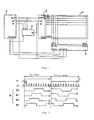
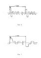
- an X-Y matrix type liquid crystal display panel is driven in either of the following two well-known methods: so-called A method in which the polarity of applied voltage is reversed in one horizontal scanning period as shown in Fig. 6, and so-called B method in which the polarity of applied voltage is reversed for each frame as shown in Fig. 7.
- the waveforms shown in Figs. 6 and 7 include waveform distortion caused by the electrostatic capacity of the liquid crystal panel and by the resistance of the transparent electrodes.
- the A method provides a smaller ratio of waveform frequency variation by display pattern than the B method does (the frequency change ratio is 2 in the A method whereas it is N in the B method when the duty ratio is N), but provides higher frequency in general, resulting in larger power consumption.
- the A method is influenced significantly by waveform distortion so that the effective applied voltage drops. Because of this reason, the A method is hardly used for large liquid crystal display panels.
- an X-Y matrix type liquid crystal display panel is driven mostly by the B method.
- the B method tends to cause irregular picture and crosstalk which deteriorates the picture quality seriously.
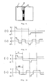
- Fig. 8 shows a typical crosstalk phenomenon. It is shown that a pattern where black portions 2 should be normally displayed against the white background 1 suffers crosstalk so that portion 3 which should be white become gray.
- the driving waveforms for the portions 1 and 3 are shown in Figs. 9(1) and 9(2), respectively.
- the waveform of Fig. 9(1) that is, in the portion 1 in Fig. 8
- the driving frequency component by the display pattern is mainly low frequency
- the driving frequency component by the display pattern is mainly high frequency.
- the difference in the frequency component of the driving waveforms results in a conspicuous crosstalk phenomenon.
- crosstalk can be caused by the diversified frequency characteristic of the threshold voltage of the liquid crystal display panel or by the variation of effective voltage caused by distorted driving waveform.
- the former cause occurs when the threshold voltage of the liquid crystal display panel changes in a driving frequency band although the effective voltage is constant.
- the driving frequency band varies depending upon the driving method.
- the frequency variation ratios of the conventional A and B methods are 2 and N (N is a duty ratio), respectively.
- N is a duty ratio
- a driving method from which the above problems are eliminated has been proposed.
- the proposed method is to reverse the polarity of driving voltage applied to the liquid crystal display panel at intervals of specified horizontal scanning periods.
- the advantage of the B method can be made use of, while power consumption is minimized.
- the driving waveforms in which the polarity of the waveforms of Figs. 9(1) and 9(2) is reversed every four horizontal scanning periods (4H) are shown in Figs. 10(1) and 10(2), respectively.
- the frequency of polarity reversing signal is the major component of the driving frequency, so that the influence by the frequency by display pattern is reduced.
- the driving frequency having a low frequency component near the frame frequency is shifted to the higher frequency side so as to contract and equalize the driving frequency component for each picture element.
- the waveform distortion is also equalized as shown in Fig. 10, and the effective voltage value is levelled to some extent in this method.
- the above proposed method has an effect of reducing crosstalk phenomenon. But it has another problem that linear display irregularity is generated along the scanning lines when polarity is reversed. This display irregularity is caused by the following reason.
- Figs. 11(1) through 11(5) show examples of driving waveforms in the liquid crystal display device.
- waveform distortion caused by the electrostatic capacity of the liquid crystal panel and by the resistance of the transparent electrodes is also taken into account.
- Figs. 11(1) and 11(2) show the waveform of driving voltage applied to the scanning electrodes.
- the waveform of Fig. 11(1) is for the case where a selection pulse is generated immediately after the reversal of polarity, and the waveform of Fig. 11(2) is for another case.
- Fig. 11(3) shows the waveform of driving voltage applied to the signal electrodes. This waveform is for the case where all picture elements are turned off.
- Fig. 11(4) shows the potential difference between the waveform of Fig. 11(1) and that of Fig. 11(3)
- Fig. 11(5) shows the potential difference between the waveform of Fig. 11(2) and that of Fig. 11(3). Both are the waveforms of voltage applied to the picture elements. As shown, waveform distortion is different between Fig.
- crosstalk occurs in the conventional liquid crystal display device, and if measure is taken to eliminate the crosstalk, linear display irregularity or meandering phenomenon is observed on the screen.
- an object of the present invention is to provide a liquid crystal display device capable of producing a uniform and high quality display.
- Another object of the present invention is to provide a liquid crystal display device driving method which realizes a uniform and high quality display free from crosstalk, display irregularity and meandering phenomenon.
- a liquid crystal display device comprises an X-Y matrix type liquid crystal display panel in which M pcs. of signal electrodes (M > 1) and N pcs. of scanning electrodes (N ⁇ 1) are arranged in a matrix, and means for reversing the polarity of the voltage applied to the liquid crystal display panel at an interval of n horizontal scanning period (1 ⁇ n ⁇ N) as well as for setting the reversing timing at random at an interval of the predetermined number of frames.
- the driving frequency is independent of the display pattern and governed by the frequency of a polarity-reversing signal.
- the polarity reversing timing changes at randam every predetermined number of frames, say, every two frames, so that the effective voltage values on the scanning lines are levelled.
- a liquid crystal display device contain an X-Y matrix type liquid crystal display panel comprising a pair of insulating substrates with a liquid crystal layer sandwitched therebetween, N pcs. of scanning electrodes provided on the inner side of one of the insulating substrates, M pcs. of signal electrodes provided on the inner side of the other substrate, the scanning electrodes and the signal electrodes crossing each other at a right angle.
- N 200
- M is 640, although the numbers for M and N are not limited to these.
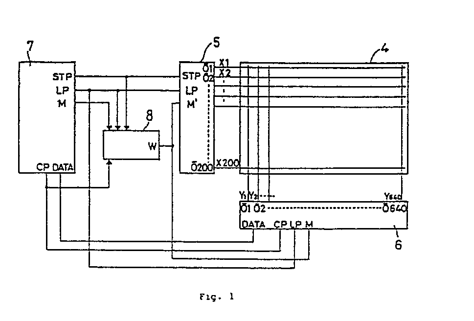
- an X-Y matrix type liquid crystal display panel 4 (hereinafter referred to simply as a liquid crystal panel) comprises a liquid crystal layer placed between a pair of insulating substrates, scanning electrodes X1, X2, ... X200 formed on the inner side of one of the pair of insulating substrates, and signal electrodes Y1, Y2, ... Y640 formed on the inner side of the other insulating substrate, the scanning electrodes crossing the signal electrodes.
- the insulating substrate may be made of a conducting member with insulating film applied thereon, or made of a conducting member alone. Insulating films are provided on the signal electrodes and scanning electrodes.
- a controller 7 supplies the drivers 5 and 6 with specified signals. Specifically, the controller 7 outputs display data DATA, dot clock pulse CP for taking the display data and latch pulse LP to the signal electrode driver 6. When 640 dot clock pulses CP have been output to take the data for one line in the signal electrode driver 6, the latch pulse LP is output, making the signal electrode driver 6 latch the data for one line.
- the signal electrode driver 6 outputs 640 liquid crystal-driving signals on the basis of the latched data. In the present embodiment of the invention, it is assumed the latch pulse is output every one horizontal scanning period (1H) as shown in Fig. 2.
- the controller 7 outputs start pulse STP and latch pulse LP to the scanning electrode driver 5.
- the scanning electrode driver 5 uses the latch pulse LP as a clock pulse, the scanning electrode driver 5 shifts the selection waveform sequentially.
- the period required for outputting 200 latch pulses LP to complete selection of all the scanning electrodes is one frame.
- One frame is normally set at 50 to 60 Hz.
- a polarity reversal control circuit 8 generates a reversal control signal W which reverses the polarity of the voltage waveform applied to the liquid crystal panel 4 at an interval of n (1 ⁇ n ⁇ 200) horizontal scanning lines and which changes the reversing timing at random every predetermined number of frames, say, every two frames.
- Start pulse STP, latch pulse LP, dot clock pulse CP and alternating signal M are supplied from the controller 7 to the polarity reversal control circuit 8.
- the alternating signal M is a binary signal which reverses for each frame, as shown in Fig. 2.
- the B driving method uses an alternating signal M whose polarity reverses for each frame.
- the A method uses an alternating signal M whose polarity changes for each 1/2 horizontal scanning period.
- the alternating signal M is supplied as it is to the scanning and signal electrode drivers 5 and 6.
- the alternating signal M is changed into a reversal control signal W by the polarity reversal control circuit 8 before being supplied to the drivers 5 and 6.
- the reversal control signal W provides four different phases ⁇ 0, ⁇ 1, ⁇ 2, ⁇ 3.
- Reversal control signal W of one of the four phases is selected at random at an interval of predetermined number of frames, say, of two frames. This irregularity or randomness of the phase contributes to the uniform display free from crosstalk.
- the reversing period need not be limited to 4H.
- the polarity reversal control circuit 8 comprises a random number generating circuit 9, a latch circuit 10 for storing the output from the random number generating circuit 9 for predetermined number of frames, say, for two frames, a frequency dividing counter 11 which starts counting by reading the initial value at an interval of the predetermined number of frames, say , two frames, an exclusive OR circuit 12 which generates a reversal control signal W by taking the exclusive OR between the output from the frequency dividing counter 11 and an alternating signal M, a first circuit 13 for supplying clock signals S1 to the latch circuit 10, and a second circuit 14 for supplying operation signals S2 to the frequency dividing counter 11.
- the first and second circuits 13 and 14 contain first and second D flip flops 15 and 16, respectively.
- the random number generating circuit 9 comprises an oscillator 17 which oscillates by itself at nearly the same frequency as the horizontal scanning frequency, and a quaternary counter 18 which divides the output from the oscillator 17 into four.
- the quaternary counter 18 comprises third and fourth D flip flops 19 and 20.
- the quaternary counter 18 sets the polarity reversing period "n" at 4H.
- n is set at 10H.
- the polarity reversing period set by the quaternary or decimal counter is determined by the frequency of the self oscillator 17, the value for "n" can be changed as desired.
- This second function is based on the self oscillator 17 which oscillates by itself at a certain appropriate frequency, independent of the signal systems of the controller 7.
- the output from the quaternary counter 18 of the random number generating circuit 9 is retained by a signal S1 in the latch circuit 10 at an interval of predetermined number of frames, say, two frames. The output thus retained is further latched by a signal S2 in the frequency dividing counter 11.
- the frequency dividing counter 11 generates a signal for reversing polarity at 4H intervals.
- the exclusive OR circuit 12 generates a polarity reversal control signal W by taking the exclusive OR between the output from the frequency dividing counter 11 and an alternating signal M from the controller 7. The signal W is supplied to the input terminals M and M′ of the drivers 5 and 6 to change the driving voltage at random.
- Fig. 4 The signal waveform at each part of Fig. 3 is shown in Fig. 4.
- the waveform of a polarity reversal control signal W is shown in comparison with that of an alternating signal M in Fig. 5.
- Fig. 5 indicates that a polarity reversal control signal W of the phase ⁇ 3 is generated for the Fth and (F+1)th frames, a polarity reversal control signal W of the phase ⁇ 0 for the (F+2)th and (F+3)th frames, and a polarity reversal control signal W of the phase ⁇ 1 for the (F+4)th and (F+5)th frames at random.
- the polarity reversal control signal W of each phase is reversed in its polarity for each frame so as to enable alternating drive which helps lengthen the life of the liquid crystal. This reversal of the polarity is realized by the function of the exclusive OR circuit 12.
- the waveform of the voltage applied to the liquid crystal panel (namely the liquid crystal-driving voltage) is reversed in its polarity at intervals of a plurality of scanning lines in each frame, the driving frequency change ratio is small, and the driving frequency component is independent of the display pattern and dominated by the frequency of a polarity-reversing signal. Consequently, crosstalk is hardly generated.
- the polarity reversing timing is set at random for every predetermined number of frames, say, every two frames, the effective voltage values on the scanning lines are equalized. Therefore, the present invention is extremely effective in producing a picture free from linear display irregularity attributed to the polarity reversal and therefore free from the meandering irregularity.
- the interval of changing the polarity-reversing timing is two frames, although it need not be limited to two frames.
- the polarity-reversing timing may be changed at any intervals of a plurality of frames.
Abstract
Description
- The present invention relates to a liquid crystal display device containing an X-Y matrix type liquid crystal display panel.
- Conventionally, an X-Y matrix type liquid crystal display panel is driven in either of the following two well-known methods: so-called A method in which the polarity of applied voltage is reversed in one horizontal scanning period as shown in Fig. 6, and so-called B method in which the polarity of applied voltage is reversed for each frame as shown in Fig. 7. The waveforms shown in Figs. 6 and 7 include waveform distortion caused by the electrostatic capacity of the liquid crystal panel and by the resistance of the transparent electrodes. The A method provides a smaller ratio of waveform frequency variation by display pattern than the B method does (the frequency change ratio is 2 in the A method whereas it is N in the B method when the duty ratio is N), but provides higher frequency in general, resulting in larger power consumption. Besides, with a larger liquid crystal display panel in which the liquid crystal capacity and the electrode resistance increase, the A method is influenced significantly by waveform distortion so that the effective applied voltage drops. Because of this reason, the A method is hardly used for large liquid crystal display panels.
- Presently, therefore, an X-Y matrix type liquid crystal display panel is driven mostly by the B method. For a large high density liquid crystal panel in which the number of time divisions exceeds 100, however, the B method tends to cause irregular picture and crosstalk which deteriorates the picture quality seriously.
- Fig. 8 shows a typical crosstalk phenomenon. It is shown that a pattern where
black portions 2 should be normally displayed against thewhite background 1 suffers crosstalk so thatportion 3 which should be white become gray. The driving waveforms for theportions portion 1 in Fig. 8, the driving frequency component by the display pattern is mainly low frequency, whereas in the waveform of Fig. 9(2), that is, in theportions 3 in Fig. 8, the driving frequency component by the display pattern is mainly high frequency. The difference in the frequency component of the driving waveforms results in a conspicuous crosstalk phenomenon. In other words, crosstalk can be caused by the diversified frequency characteristic of the threshold voltage of the liquid crystal display panel or by the variation of effective voltage caused by distorted driving waveform. - The former cause occurs when the threshold voltage of the liquid crystal display panel changes in a driving frequency band although the effective voltage is constant. The driving frequency band varies depending upon the driving method. As mentioned above, the frequency variation ratios of the conventional A and B methods are 2 and N (N is a duty ratio), respectively. When the threshold voltage of the liquid crystal display panel changes with frequency, the A method is advantageous over the B method in terms of the crosstalk phenomenon because the driving frequency variation ratio is smaller in the A method. On the other hand, the A method has a disadvantage of larger power consumption.
- A driving method from which the above problems are eliminated has been proposed. The proposed method is to reverse the polarity of driving voltage applied to the liquid crystal display panel at intervals of specified horizontal scanning periods. According to this method, the advantage of the B method can be made use of, while power consumption is minimized. To explain this method, the driving waveforms in which the polarity of the waveforms of Figs. 9(1) and 9(2) is reversed every four horizontal scanning periods (4H) are shown in Figs. 10(1) and 10(2), respectively. In these waveforms, the frequency of polarity reversing signal is the major component of the driving frequency, so that the influence by the frequency by display pattern is reduced. Namely, in this method, the driving frequency having a low frequency component near the frame frequency is shifted to the higher frequency side so as to contract and equalize the driving frequency component for each picture element. Moreover, the waveform distortion is also equalized as shown in Fig. 10, and the effective voltage value is levelled to some extent in this method.
- The above proposed method has an effect of reducing crosstalk phenomenon. But it has another problem that linear display irregularity is generated along the scanning lines when polarity is reversed. This display irregularity is caused by the following reason.
- Figs. 11(1) through 11(5) show examples of driving waveforms in the liquid crystal display device. In these figures, waveform distortion caused by the electrostatic capacity of the liquid crystal panel and by the resistance of the transparent electrodes is also taken into account.
- Figs. 11(1) and 11(2) show the waveform of driving voltage applied to the scanning electrodes. The waveform of Fig. 11(1) is for the case where a selection pulse is generated immediately after the reversal of polarity, and the waveform of Fig. 11(2) is for another case. Fig. 11(3) shows the waveform of driving voltage applied to the signal electrodes. This waveform is for the case where all picture elements are turned off. Fig. 11(4) shows the potential difference between the waveform of Fig. 11(1) and that of Fig. 11(3), and Fig. 11(5) shows the potential difference between the waveform of Fig. 11(2) and that of Fig. 11(3). Both are the waveforms of voltage applied to the picture elements. As shown, waveform distortion is different between Fig. 11(4) and Fig. 11(5). This difference in the waveform distortion causes a uniform effective voltage to be applied to picture elements, resulting in the linear display irregularity. This problem can be solved by shifting the polarity reversing point by 1H (one horizontal scanning period) in each frame to equalize the waveform distortion in each scanning line, thereby making the effective voltage uniform. In this case, however, a driving frequency component smaller than the frame frequency is produced. This results in meandering display irregularity which occurs in the downward direction on the screen during the sequential scanning.
- As mentioned above, crosstalk occurs in the conventional liquid crystal display device, and if measure is taken to eliminate the crosstalk, linear display irregularity or meandering phenomenon is observed on the screen.
- Accordingly, an object of the present invention is to provide a liquid crystal display device capable of producing a uniform and high quality display.
- Another object of the present invention is to provide a liquid crystal display device driving method which realizes a uniform and high quality display free from crosstalk, display irregularity and meandering phenomenon.
- Other objects and further scope of applicability of the present invention will become apparent from the detailed description given hereinafter. It should be understood, however, that the detailed description and specific examples, while indicating preferred embodiments of the invention, are given by way of illustration only, since various changes and modifications within the spirit and scope of the invention will become apparent to those skilled in the art from this detailed description.
- To achieve the above objects, according to an embodiment of the present invention, a liquid crystal display device comprises an X-Y matrix type liquid crystal display panel in which M pcs. of signal electrodes (M > 1) and N pcs. of scanning electrodes (N < 1) are arranged in a matrix, and means for reversing the polarity of the voltage applied to the liquid crystal display panel at an interval of n horizontal scanning period (1 < n < N) as well as for setting the reversing timing at random at an interval of the predetermined number of frames.
- In the liquid crystal display device of the above construction, the driving frequency is independent of the display pattern and governed by the frequency of a polarity-reversing signal. In addition, the polarity reversing timing changes at randam every predetermined number of frames, say, every two frames, so that the effective voltage values on the scanning lines are levelled.
- The present invention will become more fully understood from the detailed description given hereinbelow and the accompanying drawings which are given by way of illustration only, and thus are not limitative of the present invention and wherein:
- Fig. 1 is a block circuit diagram of the liquid crystal display device of an embodiment of the present invention;
- Fig. 2 is a chart of signal waveforms in the essential parts thereof;
- Fig. 3 is a circuit diagram showing in detail the polarity-reversal control circuit shown in Fig. 1;
- Fig. 4 is a waveform chart of signals supplied to various parts of the circuit shown in Fig. 3;
- Fig. 5 is a chart for explaining one of the signals shown in Fig. 4; and
- Figs. 6, 7, 8, 9, 10 and 11 are the drawings explaining the conventional liquid crystal display device.
- According to an embodiment of the present invention, a liquid crystal display device contain an X-Y matrix type liquid crystal display panel comprising a pair of insulating substrates with a liquid crystal layer sandwitched therebetween, N pcs. of scanning electrodes provided on the inner side of one of the insulating substrates, M pcs. of signal electrodes provided on the inner side of the other substrate, the scanning electrodes and the signal electrodes crossing each other at a right angle. In the following description, it is assumed that N is 200 and M is 640, although the numbers for M and N are not limited to these.
- Referring to Fig. 1 which shows the embodiment of the invention, an X-Y matrix type liquid crystal display panel 4 (hereinafter referred to simply as a liquid crystal panel) comprises a liquid crystal layer placed between a pair of insulating substrates, scanning electrodes X₁, X₂, ... X₂₀₀ formed on the inner side of one of the pair of insulating substrates, and signal electrodes Y₁, Y₂, ... Y₆₄₀ formed on the inner side of the other insulating substrate, the scanning electrodes crossing the signal electrodes. Here, the insulating substrate may be made of a conducting member with insulating film applied thereon, or made of a conducting member alone. Insulating films are provided on the signal electrodes and scanning electrodes. 5 is a scanning electrodes driver, and 6 is a signal electrode driver. A controller 7 supplies the
drivers signal electrode driver 6. When 640 dot clock pulses CP have been output to take the data for one line in thesignal electrode driver 6, the latch pulse LP is output, making thesignal electrode driver 6 latch the data for one line. Thesignal electrode driver 6 outputs 640 liquid crystal-driving signals on the basis of the latched data. In the present embodiment of the invention, it is assumed the latch pulse is output every one horizontal scanning period (1H) as shown in Fig. 2. - The controller 7 outputs start pulse STP and latch pulse LP to the
scanning electrode driver 5. Using the latch pulse LP as a clock pulse, thescanning electrode driver 5 shifts the selection waveform sequentially. The period required for outputting 200 latch pulses LP to complete selection of all the scanning electrodes is one frame. One frame is normally set at 50 to 60 Hz. - A polarity
reversal control circuit 8 generates a reversal control signal W which reverses the polarity of the voltage waveform applied to theliquid crystal panel 4 at an interval of n (1 < n < 200) horizontal scanning lines and which changes the reversing timing at random every predetermined number of frames, say, every two frames. Start pulse STP, latch pulse LP, dot clock pulse CP and alternating signal M are supplied from the controller 7 to the polarityreversal control circuit 8. The alternating signal M is a binary signal which reverses for each frame, as shown in Fig. 2. - The B driving method uses an alternating signal M whose polarity reverses for each frame. The A method uses an alternating signal M whose polarity changes for each 1/2 horizontal scanning period. Conventionally, the alternating signal M is supplied as it is to the scanning and
signal electrode drivers reversal control circuit 8 before being supplied to thedrivers reversal control signal 8 reverses its polarity at n = 4H (4 horizontal scanning periods) interval in each frame, and the polarity of the signal W at the beginning of each frame is opposite to that at the beginning of the preceding frame. The reversal control signal W provides four different phases φ₀, φ₁, φ₂, φ₃. Reversal control signal W of one of the four phases is selected at random at an interval of predetermined number of frames, say, of two frames. This irregularity or randomness of the phase contributes to the uniform display free from crosstalk. The reversing period need not be limited to 4H. - Fig. 3 shows a specific example of the polarity
reversal control circuit 8. Referring to Fig. 3, the polarityreversal control circuit 8 comprises a random number generating circuit 9, a latch circuit 10 for storing the output from the random number generating circuit 9 for predetermined number of frames, say, for two frames, a frequency dividing counter 11 which starts counting by reading the initial value at an interval of the predetermined number of frames, say , two frames, an exclusive ORcircuit 12 which generates a reversal control signal W by taking the exclusive OR between the output from the frequency dividing counter 11 and an alternating signal M, afirst circuit 13 for supplying clock signals S₁ to the latch circuit 10, and asecond circuit 14 for supplying operation signals S₂ to the frequency dividing counter 11. The first andsecond circuits D flip flops - The random number generating circuit 9 comprises an
oscillator 17 which oscillates by itself at nearly the same frequency as the horizontal scanning frequency, and a quaternary counter 18 which divides the output from theoscillator 17 into four. The quaternary counter 18 comprises third and fourthD flip flops self oscillator 17, the value for "n" can be changed as desired. - In addition to the function of determining the value for "n", the random number generating circuit 9 has a function of generating "n" kinds of phase (four kinds when n = 4H, and 10 kinds when n = 10H). This second function is based on the
self oscillator 17 which oscillates by itself at a certain appropriate frequency, independent of the signal systems of the controller 7. The output from the quaternary counter 18 of the random number generating circuit 9 is retained by a signal S₁ in the latch circuit 10 at an interval of predetermined number of frames, say, two frames. The output thus retained is further latched by a signal S₂ in the frequency dividing counter 11. The frequency dividing counter 11 generates a signal for reversing polarity at 4H intervals. The exclusive ORcircuit 12 generates a polarity reversal control signal W by taking the exclusive OR between the output from the frequency dividing counter 11 and an alternating signal M from the controller 7. The signal W is supplied to the input terminals M and M′ of thedrivers - The signal waveform at each part of Fig. 3 is shown in Fig. 4. The waveform of a polarity reversal control signal W is shown in comparison with that of an alternating signal M in Fig. 5. Fig. 5 indicates that a polarity reversal control signal W of the phase φ₃ is generated for the Fth and (F+1)th frames, a polarity reversal control signal W of the phase φ₀ for the (F+2)th and (F+3)th frames, and a polarity reversal control signal W of the phase φ₁ for the (F+4)th and (F+5)th frames at random. The polarity reversal control signal W of each phase is reversed in its polarity for each frame so as to enable alternating drive which helps lengthen the life of the liquid crystal. This reversal of the polarity is realized by the function of the exclusive OR
circuit 12. - As a result, driving voltage, whose polarity is reversed regularly at intervals of n horizontal periods in each frame at a timing which changes randomly every predetermined number of frames, say, every two frames, is applied to the liquid crystal cells constituting the liquid crystal panel.
- An embodiment of the present invention has been described above. All the other components than the polarity
reversal control circuit 8 shown in Fig. 1 are conventional ones. Therefore, the liquid crystal display device of the present invention is realized easily by connecting the polarityreversal control circuit 8 to an existing system. - According to the present invention, as described above, since the waveform of the voltage applied to the liquid crystal panel (namely the liquid crystal-driving voltage) is reversed in its polarity at intervals of a plurality of scanning lines in each frame, the driving frequency change ratio is small, and the driving frequency component is independent of the display pattern and dominated by the frequency of a polarity-reversing signal. Consequently, crosstalk is hardly generated. Moreover, since the polarity reversing timing is set at random for every predetermined number of frames, say, every two frames, the effective voltage values on the scanning lines are equalized. Therefore, the present invention is extremely effective in producing a picture free from linear display irregularity attributed to the polarity reversal and therefore free from the meandering irregularity.
- In the above embodiment, the interval of changing the polarity-reversing timing is two frames, although it need not be limited to two frames. The polarity-reversing timing may be changed at any intervals of a plurality of frames.
- The above description is based on the assumption that the number of scanning electrodes is 200 and the number of signal electrodes is 640. These figures for the numbers of electrodes may be changed as desired. These numbers of electrodes may be considered to be provided in the effective display region.
- While only certain embodiments of the present invention have been described, it will be apparent to those skilled in the art that various changes and modifications may be made therein without departing from the spirit and scope of the present invention as claimed.
- There are described above novel features which the skilled man will appreciate give rise to advantages. These are each independent aspects of the invention to be covered by the present application, irrespective of whether or not they are included within the scope of the following claims.
Claims (5)
Applications Claiming Priority (2)
| Application Number | Priority Date | Filing Date | Title |
|---|---|---|---|
| JP133817/87 | 1987-05-29 | ||
| JP62133817A JPS63298287A (en) | 1987-05-29 | 1987-05-29 | Liquid crystal display device |
Publications (2)
| Publication Number | Publication Date |
|---|---|
| EP0295802A1 true EP0295802A1 (en) | 1988-12-21 |
| EP0295802B1 EP0295802B1 (en) | 1992-03-11 |
Family
ID=15113736
Family Applications (1)
| Application Number | Title | Priority Date | Filing Date |
|---|---|---|---|
| EP88304847A Expired EP0295802B1 (en) | 1987-05-29 | 1988-05-27 | Liquid crystal display device |
Country Status (4)
| Country | Link |
|---|---|
| US (1) | US4926168A (en) |
| EP (1) | EP0295802B1 (en) |
| JP (1) | JPS63298287A (en) |
| DE (1) | DE3868990D1 (en) |
Cited By (15)
| Publication number | Priority date | Publication date | Assignee | Title |
|---|---|---|---|---|
| EP0525852A1 (en) * | 1991-07-09 | 1993-02-03 | Koninklijke Philips Electronics N.V. | Display device |
| EP0597117A1 (en) * | 1992-05-14 | 1994-05-18 | Seiko Epson Corporation | Liquid crystal display and electronic equipment using the liquid crystal display |
| US6295043B1 (en) | 1994-06-06 | 2001-09-25 | Canon Kabushiki Kaisha | Display and its driving method |
| WO2006121753A2 (en) * | 2005-05-05 | 2006-11-16 | Qualcomm Incorporated | System and method of driving a mems display device |
| US7601571B2 (en) | 2004-07-02 | 2009-10-13 | Idc, Llc | Methods of manufacturing interferometric modulators with thin film transistors |
| US7852542B2 (en) | 2004-08-27 | 2010-12-14 | Qualcomm Mems Technologies, Inc. | Current mode display driver circuit realization feature |
| US7957589B2 (en) | 2007-01-25 | 2011-06-07 | Qualcomm Mems Technologies, Inc. | Arbitrary power function using logarithm lookup table |
| US8085461B2 (en) | 2004-09-27 | 2011-12-27 | Qualcomm Mems Technologies, Inc. | Systems and methods of actuating MEMS display elements |
| US8243014B2 (en) | 2004-09-27 | 2012-08-14 | Qualcomm Mems Technologies, Inc. | Method and system for reducing power consumption in a display |
| US8344997B2 (en) | 2004-09-27 | 2013-01-01 | Qualcomm Mems Technologies, Inc. | Method and system for writing data to electromechanical display elements |
| US8405649B2 (en) | 2009-03-27 | 2013-03-26 | Qualcomm Mems Technologies, Inc. | Low voltage driver scheme for interferometric modulators |
| US8514169B2 (en) | 2004-09-27 | 2013-08-20 | Qualcomm Mems Technologies, Inc. | Apparatus and system for writing data to electromechanical display elements |
| US8928967B2 (en) | 1998-04-08 | 2015-01-06 | Qualcomm Mems Technologies, Inc. | Method and device for modulating light |
| US8971675B2 (en) | 2006-01-13 | 2015-03-03 | Qualcomm Mems Technologies, Inc. | Interconnect structure for MEMS device |
| US9110289B2 (en) | 1998-04-08 | 2015-08-18 | Qualcomm Mems Technologies, Inc. | Device for modulating light with multiple electrodes |
Families Citing this family (44)
| Publication number | Priority date | Publication date | Assignee | Title |
|---|---|---|---|---|
| DE68920239T2 (en) * | 1988-09-07 | 1995-05-04 | Seiko Epson Corp | Method of operating a liquid crystal display. |
| EP0374845B1 (en) * | 1988-12-23 | 1995-04-12 | Fujitsu Limited | Method and apparatus for driving a liquid crystal display panel |
| US5301047A (en) * | 1989-05-17 | 1994-04-05 | Hitachi, Ltd. | Liquid crystal display |
| JPH0335219A (en) * | 1989-06-30 | 1991-02-15 | Sharp Corp | Display device |
| JPH03132692A (en) * | 1989-10-18 | 1991-06-06 | Matsushita Electric Ind Co Ltd | Method for driving liquid crystal display device and its driving circuit |
| US5610627A (en) * | 1990-08-10 | 1997-03-11 | Sharp Kabushiki Kaisha | Clocking method and apparatus for display device with calculation operation |
| JP2826772B2 (en) * | 1991-01-07 | 1998-11-18 | キヤノン株式会社 | Liquid crystal display |
| JP3001317B2 (en) * | 1992-02-05 | 2000-01-24 | 日本電気株式会社 | Driving method of active matrix type liquid crystal display device |
| US5526014A (en) * | 1992-02-26 | 1996-06-11 | Nec Corporation | Semiconductor device for driving liquid crystal display panel |
| US5594466A (en) * | 1992-10-07 | 1997-01-14 | Sharp Kabushiki Kaisha | Driving device for a display panel and a driving method of the same |
| JP3306173B2 (en) * | 1993-07-06 | 2002-07-24 | オリンパス光学工業株式会社 | Video display device |
| JP2962985B2 (en) * | 1993-12-22 | 1999-10-12 | シャープ株式会社 | Liquid crystal display |
| JP3648689B2 (en) * | 1994-09-06 | 2005-05-18 | 日本テキサス・インスツルメンツ株式会社 | Liquid crystal panel driving method and apparatus |
| JP3107980B2 (en) * | 1994-09-29 | 2000-11-13 | シャープ株式会社 | Liquid crystal display |
| JPH08101669A (en) * | 1994-09-30 | 1996-04-16 | Semiconductor Energy Lab Co Ltd | Display device drive circuit |
| JP3612895B2 (en) * | 1996-10-23 | 2005-01-19 | カシオ計算機株式会社 | Liquid crystal display |
| US6496172B1 (en) * | 1998-03-27 | 2002-12-17 | Semiconductor Energy Laboratory Co., Ltd. | Liquid crystal display device, active matrix type liquid crystal display device, and method of driving the same |
| US6057818A (en) * | 1998-08-05 | 2000-05-02 | Hewlett-Packard Company | Liquid crystal display driven by raised cosine drive signal |
| JP2000258750A (en) | 1999-03-11 | 2000-09-22 | Toshiba Corp | Liquid crystal display device |
| US7098884B2 (en) * | 2000-02-08 | 2006-08-29 | Semiconductor Energy Laboratory Co., Ltd. | Semiconductor display device and method of driving semiconductor display device |
| KR100438521B1 (en) * | 2001-05-25 | 2004-07-03 | 엘지.필립스 엘시디 주식회사 | Liquid Crystal Display With Light Shutter and Apparatus and Method of Driving The Same |
| TW552573B (en) * | 2001-08-21 | 2003-09-11 | Samsung Electronics Co Ltd | Liquid crystal display and driving method thereof |
| JP4599897B2 (en) * | 2004-06-10 | 2010-12-15 | ソニー株式会社 | Apparatus and method for driving display optical device |
| US7889163B2 (en) | 2004-08-27 | 2011-02-15 | Qualcomm Mems Technologies, Inc. | Drive method for MEMS devices |
| US7843410B2 (en) | 2004-09-27 | 2010-11-30 | Qualcomm Mems Technologies, Inc. | Method and device for electrically programmable display |
| US7136213B2 (en) | 2004-09-27 | 2006-11-14 | Idc, Llc | Interferometric modulators having charge persistence |
| US7724993B2 (en) | 2004-09-27 | 2010-05-25 | Qualcomm Mems Technologies, Inc. | MEMS switches with deforming membranes |
| US8878825B2 (en) | 2004-09-27 | 2014-11-04 | Qualcomm Mems Technologies, Inc. | System and method for providing a variable refresh rate of an interferometric modulator display |
| US7679627B2 (en) | 2004-09-27 | 2010-03-16 | Qualcomm Mems Technologies, Inc. | Controller and driver features for bi-stable display |
| US7675669B2 (en) | 2004-09-27 | 2010-03-09 | Qualcomm Mems Technologies, Inc. | Method and system for driving interferometric modulators |
| TWI329296B (en) * | 2005-01-25 | 2010-08-21 | Au Optronics Corp | Liquid crystal display and inversion method |
| EP1878001A1 (en) | 2005-05-05 | 2008-01-16 | QUALCOMM Incorporated, Inc. | Dynamic driver ic and display panel configuration |
| US7948457B2 (en) | 2005-05-05 | 2011-05-24 | Qualcomm Mems Technologies, Inc. | Systems and methods of actuating MEMS display elements |
| JP2007121832A (en) * | 2005-10-31 | 2007-05-17 | Oki Electric Ind Co Ltd | Drive unit of liquid crystal display device |
| US20070120804A1 (en) * | 2005-11-25 | 2007-05-31 | Jimi Hung | LCD module and control method |
| US8391630B2 (en) | 2005-12-22 | 2013-03-05 | Qualcomm Mems Technologies, Inc. | System and method for power reduction when decompressing video streams for interferometric modulator displays |
| US8194056B2 (en) | 2006-02-09 | 2012-06-05 | Qualcomm Mems Technologies Inc. | Method and system for writing data to MEMS display elements |
| US8049713B2 (en) | 2006-04-24 | 2011-11-01 | Qualcomm Mems Technologies, Inc. | Power consumption optimized display update |
| US7702192B2 (en) | 2006-06-21 | 2010-04-20 | Qualcomm Mems Technologies, Inc. | Systems and methods for driving MEMS display |
| US7777715B2 (en) | 2006-06-29 | 2010-08-17 | Qualcomm Mems Technologies, Inc. | Passive circuits for de-multiplexing display inputs |
| US8736590B2 (en) | 2009-03-27 | 2014-05-27 | Qualcomm Mems Technologies, Inc. | Low voltage driver scheme for interferometric modulators |
| TWI656112B (en) | 2016-03-24 | 2019-04-11 | 日商三菱瓦斯化學股份有限公司 | Composition for novel optical material containing thiol compound |
| CN106486086B (en) * | 2017-01-05 | 2019-07-30 | 京东方科技集团股份有限公司 | A kind of source electrode driving device, its polarity reversion control method and liquid crystal display device |
| CN113889050A (en) * | 2021-10-12 | 2022-01-04 | 集创北方(珠海)科技有限公司 | Polarity conversion method of liquid crystal panel and liquid crystal display |
Citations (3)
| Publication number | Priority date | Publication date | Assignee | Title |
|---|---|---|---|---|
| EP0020027A1 (en) * | 1979-05-03 | 1980-12-10 | National Research Development Corporation | Apparatus for displaying two waveforms |
| CH645473A5 (en) * | 1980-08-05 | 1984-09-28 | Videlec Ag | Method for activating a liquid crystal display |
| EP0216168A2 (en) * | 1985-08-29 | 1987-04-01 | Canon Kabushiki Kaisha | Method of driving a display panel |
Family Cites Families (1)
| Publication number | Priority date | Publication date | Assignee | Title |
|---|---|---|---|---|
| GB2165984B (en) * | 1984-10-11 | 1988-05-05 | Hitachi Ltd | Liquid crystal display device |
-
1987
- 1987-05-29 JP JP62133817A patent/JPS63298287A/en active Pending
-
1988
- 1988-05-27 DE DE8888304847T patent/DE3868990D1/en not_active Expired - Lifetime
- 1988-05-27 EP EP88304847A patent/EP0295802B1/en not_active Expired
- 1988-05-27 US US07/198,870 patent/US4926168A/en not_active Expired - Lifetime
Patent Citations (3)
| Publication number | Priority date | Publication date | Assignee | Title |
|---|---|---|---|---|
| EP0020027A1 (en) * | 1979-05-03 | 1980-12-10 | National Research Development Corporation | Apparatus for displaying two waveforms |
| CH645473A5 (en) * | 1980-08-05 | 1984-09-28 | Videlec Ag | Method for activating a liquid crystal display |
| EP0216168A2 (en) * | 1985-08-29 | 1987-04-01 | Canon Kabushiki Kaisha | Method of driving a display panel |
Non-Patent Citations (1)
| Title |
|---|
| PATENT ABSTRACTS OF JAPAN, volume 9, no. 181 (E-331), 26th July 1985; & JP - A - 60 052 166 (MATSUSHITA) 25-03-1985 * |
Cited By (23)
| Publication number | Priority date | Publication date | Assignee | Title |
|---|---|---|---|---|
| EP0525852A1 (en) * | 1991-07-09 | 1993-02-03 | Koninklijke Philips Electronics N.V. | Display device |
| US5689282A (en) * | 1991-07-09 | 1997-11-18 | U.S. Philips Corporation | Display device with compensation for stray capacitance |
| EP0597117A1 (en) * | 1992-05-14 | 1994-05-18 | Seiko Epson Corporation | Liquid crystal display and electronic equipment using the liquid crystal display |
| EP0597117A4 (en) * | 1992-05-14 | 1994-12-07 | Seiko Epson Corp | Liquid crystal display and electronic equipment using the liquid crystal display. |
| US5576729A (en) * | 1992-05-14 | 1996-11-19 | Seiko Epson Corporation | Liquid crystal display device and electronic equipment using the same |
| US6295043B1 (en) | 1994-06-06 | 2001-09-25 | Canon Kabushiki Kaisha | Display and its driving method |
| US6570553B2 (en) | 1994-06-06 | 2003-05-27 | Canon Kabushiki Kaisha | Display and its driving method |
| US9110289B2 (en) | 1998-04-08 | 2015-08-18 | Qualcomm Mems Technologies, Inc. | Device for modulating light with multiple electrodes |
| US8928967B2 (en) | 1998-04-08 | 2015-01-06 | Qualcomm Mems Technologies, Inc. | Method and device for modulating light |
| US7601571B2 (en) | 2004-07-02 | 2009-10-13 | Idc, Llc | Methods of manufacturing interferometric modulators with thin film transistors |
| US7852542B2 (en) | 2004-08-27 | 2010-12-14 | Qualcomm Mems Technologies, Inc. | Current mode display driver circuit realization feature |
| US8085461B2 (en) | 2004-09-27 | 2011-12-27 | Qualcomm Mems Technologies, Inc. | Systems and methods of actuating MEMS display elements |
| US8243014B2 (en) | 2004-09-27 | 2012-08-14 | Qualcomm Mems Technologies, Inc. | Method and system for reducing power consumption in a display |
| US8344997B2 (en) | 2004-09-27 | 2013-01-01 | Qualcomm Mems Technologies, Inc. | Method and system for writing data to electromechanical display elements |
| US8471808B2 (en) | 2004-09-27 | 2013-06-25 | Qualcomm Mems Technologies, Inc. | Method and device for reducing power consumption in a display |
| US8514169B2 (en) | 2004-09-27 | 2013-08-20 | Qualcomm Mems Technologies, Inc. | Apparatus and system for writing data to electromechanical display elements |
| US8791897B2 (en) | 2004-09-27 | 2014-07-29 | Qualcomm Mems Technologies, Inc. | Method and system for writing data to MEMS display elements |
| US8878771B2 (en) | 2004-09-27 | 2014-11-04 | Qualcomm Mems Technologies, Inc. | Method and system for reducing power consumption in a display |
| WO2006121753A3 (en) * | 2005-05-05 | 2007-03-29 | Qualcomm Mems Technologies Inc | System and method of driving a mems display device |
| WO2006121753A2 (en) * | 2005-05-05 | 2006-11-16 | Qualcomm Incorporated | System and method of driving a mems display device |
| US8971675B2 (en) | 2006-01-13 | 2015-03-03 | Qualcomm Mems Technologies, Inc. | Interconnect structure for MEMS device |
| US7957589B2 (en) | 2007-01-25 | 2011-06-07 | Qualcomm Mems Technologies, Inc. | Arbitrary power function using logarithm lookup table |
| US8405649B2 (en) | 2009-03-27 | 2013-03-26 | Qualcomm Mems Technologies, Inc. | Low voltage driver scheme for interferometric modulators |
Also Published As
| Publication number | Publication date |
|---|---|
| DE3868990D1 (en) | 1992-04-16 |
| JPS63298287A (en) | 1988-12-06 |
| EP0295802B1 (en) | 1992-03-11 |
| US4926168A (en) | 1990-05-15 |
Similar Documents
| Publication | Publication Date | Title |
|---|---|---|
| EP0295802B1 (en) | Liquid crystal display device | |
| US5307084A (en) | Method and apparatus for driving a liquid crystal display panel | |
| US6937216B1 (en) | Electro-optical device, and electronic apparatus and display driver IC using the same | |
| US4901066A (en) | Method of driving an optical modulation device | |
| US7362299B2 (en) | Liquid crystal display device, driving circuit for the same and driving method for the same | |
| US4556880A (en) | Liquid crystal display apparatus | |
| EP0261899A2 (en) | Display device | |
| US6806858B2 (en) | Electro-optical apparatus and method of driving electro-optical material, driving circuit therefor, electronic apparatus, and display apparatus | |
| US5162932A (en) | Method of driving a liquid crystal display with minimum frequency variation of pixel voltage | |
| US5541619A (en) | Display apparatus and method of driving display panel | |
| US5298913A (en) | Ferroelectric liquid crystal display device and driving system thereof for driving the display by an integrated scanning method | |
| US6538629B1 (en) | Liquid crystal driver unit, liquid crystal driving method, and liquid crystal display device | |
| GB1592795A (en) | Data display screen systems utilising a bistable voltage-controlled medium | |
| JPS6371889A (en) | Drive circuit for display device | |
| US4701025A (en) | Liquid crystal display device with driving method to eliminate blur due to frequency dependence | |
| EP0372364B1 (en) | Method and apparatus for driving display device | |
| JPH08241060A (en) | Liquid crystal display device and its drive method | |
| KR100365657B1 (en) | Driving method of a display device and a driving circuit | |
| EP0293235B1 (en) | Display device and driving system thereof | |
| JP3436680B2 (en) | Display device drive circuit | |
| JPH1152333A (en) | Method for driving liquid crystal element as well as liquid crystal display device and electronic apparatus | |
| JP2012163897A (en) | Liquid crystal driving method, liquid crystal driving device, liquid crystal device, and electronic apparatus | |
| JPH0659645A (en) | Driving method for liquid crystal electro-optical device | |
| JPS6365493A (en) | Interface circuit for liquid crystal display device | |
| JPS6045294A (en) | Driver for liquid crystal panel |
Legal Events
| Date | Code | Title | Description |
|---|---|---|---|
| PUAI | Public reference made under article 153(3) epc to a published international application that has entered the european phase |
Free format text: ORIGINAL CODE: 0009012 |
|
| AK | Designated contracting states |
Kind code of ref document: A1 Designated state(s): DE GB |
|
| 17P | Request for examination filed |
Effective date: 19881219 |
|
| 17Q | First examination report despatched |
Effective date: 19910513 |
|
| GRAA | (expected) grant |
Free format text: ORIGINAL CODE: 0009210 |
|
| AK | Designated contracting states |
Kind code of ref document: B1 Designated state(s): DE GB |
|
| REF | Corresponds to: |
Ref document number: 3868990 Country of ref document: DE Date of ref document: 19920416 |
|
| PLBE | No opposition filed within time limit |
Free format text: ORIGINAL CODE: 0009261 |
|
| STAA | Information on the status of an ep patent application or granted ep patent |
Free format text: STATUS: NO OPPOSITION FILED WITHIN TIME LIMIT |
|
| 26N | No opposition filed | ||
| PGFP | Annual fee paid to national office [announced via postgrant information from national office to epo] |
Ref country code: DE Payment date: 20010522 Year of fee payment: 14 |
|
| PGFP | Annual fee paid to national office [announced via postgrant information from national office to epo] |
Ref country code: GB Payment date: 20010523 Year of fee payment: 14 |
|
| REG | Reference to a national code |
Ref country code: GB Ref legal event code: IF02 |
|
| PG25 | Lapsed in a contracting state [announced via postgrant information from national office to epo] |
Ref country code: GB Free format text: LAPSE BECAUSE OF NON-PAYMENT OF DUE FEES Effective date: 20020527 |
|
| PG25 | Lapsed in a contracting state [announced via postgrant information from national office to epo] |
Ref country code: DE Free format text: LAPSE BECAUSE OF NON-PAYMENT OF DUE FEES Effective date: 20021203 |
|
| GBPC | Gb: european patent ceased through non-payment of renewal fee |
Effective date: 20020527 |