EP0299208A2 - Rate responsive pacemaker - Google Patents
Rate responsive pacemaker Download PDFInfo
- Publication number
- EP0299208A2 EP0299208A2 EP88109322A EP88109322A EP0299208A2 EP 0299208 A2 EP0299208 A2 EP 0299208A2 EP 88109322 A EP88109322 A EP 88109322A EP 88109322 A EP88109322 A EP 88109322A EP 0299208 A2 EP0299208 A2 EP 0299208A2
- Authority
- EP
- European Patent Office
- Prior art keywords
- parameters
- sensor signal
- functional relationship
- pacemaker
- stimulation frequency
- Prior art date
- Legal status (The legal status is an assumption and is not a legal conclusion. Google has not performed a legal analysis and makes no representation as to the accuracy of the status listed.)
- Granted
Links
Images
Classifications
-
- A—HUMAN NECESSITIES
- A61—MEDICAL OR VETERINARY SCIENCE; HYGIENE
- A61N—ELECTROTHERAPY; MAGNETOTHERAPY; RADIATION THERAPY; ULTRASOUND THERAPY
- A61N1/00—Electrotherapy; Circuits therefor
- A61N1/18—Applying electric currents by contact electrodes
- A61N1/32—Applying electric currents by contact electrodes alternating or intermittent currents
- A61N1/36—Applying electric currents by contact electrodes alternating or intermittent currents for stimulation
- A61N1/362—Heart stimulators
- A61N1/365—Heart stimulators controlled by a physiological parameter, e.g. heart potential
- A61N1/36514—Heart stimulators controlled by a physiological parameter, e.g. heart potential controlled by a physiological quantity other than heart potential, e.g. blood pressure
- A61N1/36542—Heart stimulators controlled by a physiological parameter, e.g. heart potential controlled by a physiological quantity other than heart potential, e.g. blood pressure controlled by body motion, e.g. acceleration
Definitions
- This invention relates to a method for finding the parameters in a functional relationship between the stimulation frequency in an implantable physiological stimulating device, in particular a heart pacemaker, and a sensor signal indicative of the physical load condition of a patient.
- pacemakers including a control system for matching the stimulation frequency of a heart pacemaker to the varying work load condition of a patient, generally referred to as rate responsive pacemakers, have been disclosed.
- rate responsive pacemakers rely on the sensing of a variable related to and indicative of the work load of a patient.
- variables are for instance blood oxygen saturation, blood PH, movement and force.
- the functional relationship between the sensed variable and the stimulation frequency could be linear or non-linear, depending on e.g. sensed variable, sensor type and sensor signal processing.
- the parameters in the function must be set to values which are optimal to the individual pacemaker patient, as the sensor output signals varies from patient to patient depending on general fitness, body constitution, pacemaker placement, etc..
- the object of the present invention is to provide a method in which the parameter values are found in response to desired stimulation frequency settings, and thus provide for a more fast, safe and conveniently parameter setting.
- any function between two variables can be determined when a sufficient number of variable values is known. Therefore, a function relating the sensor signal or measured variable, m to stimulation frequency, f stim , could be determined with regard to its parameters from a number of observed values f stim1 to f stim n and m1 to m n where n at least equals the number of parameters to be set.
- the pacemaker is generally designated 10.
- a force sensor 11 is included in the pacemaker can. it should be noted here that also other sensor types and also other sensor placements could be used.
- the sensor signal is transformed in an A/D-converter block 12 into a signal m with a pulse duration proportional to the amplitude of the original sensor signal.
- the rate responsive parameters defining the constants of the function relating the sensor signal to the stimulation frequency, f stim , are introduced in a parameter block 13.
- Block 13 is under the control of a logic and timing block 15, also controlling other functions of the pacemaker (e.g. output block 18), which, except for the rate responsive part, is a convential demand pacemaker.
- Switch 14 enables a passive mode for the rate responsive function, viz. the pacemaker operates at the programmed minimum rate, while the rate which would have been present with switch 14 closed is still indicated from sensor 11.
- the program memory 16 enables the programming signal and the calculated parameter values to be stored. That signal contains i.e. the desired stimulation frequency and is received from the programmer 30 through telemetry circuitry 17.
- the parameter calculating unit could either be contained in block 15 or programmer 30.
- the patient is exposed to a low work load, for instance slow walking.
- This work load is correlated with a range of stimulation frequencies, e.g. 70 - 90 pulses per minute.
- the physician selects from this range one frequency f1 appearing to be desirable to the individual pacemaker patient.
- the same level of work load corresponds to a sensor signal value m1 indicative of said work load, which value is obtained from the pacemaker sensor.
- This work load is correlated with another range of stimulation frequencies, e.g. 130 - 150 and the physician selects also here a desireable frequency, f2.
- the corresponding sensor signal value is m2.
- the rate responsive parameters k1 and k2 can now be calculated either in the pacemaker circuitry or in the programmer by inserting m1, m2 and f1, f2 into the function.
- slope and threshold are set in a way where the physician is only confronted with desired stimulation frequencies.
- the invention has been described for a heart pacemaker just by way of example, and it should be noted that it applies to any implantable physiological stimulating device with a similar relationship between sensor signal and stimulation frequency.
Abstract
Description
- This invention relates to a method for finding the parameters in a functional relationship between the stimulation frequency in an implantable physiological stimulating device, in particular a heart pacemaker, and a sensor signal indicative of the physical load condition of a patient.
- Recently, pacemakers including a control system for matching the stimulation frequency of a heart pacemaker to the varying work load condition of a patient, generally referred to as rate responsive pacemakers, have been disclosed. Typically, rate responsive pacemakers rely on the sensing of a variable related to and indicative of the work load of a patient. Such variables are for instance blood oxygen saturation, blood PH, movement and force. The functional relationship between the sensed variable and the stimulation frequency could be linear or non-linear, depending on e.g. sensed variable, sensor type and sensor signal processing.
- Irrespective of the type of functional relationship, linear or non-linear as the case may be, the parameters in the function must be set to values which are optimal to the individual pacemaker patient, as the sensor output signals varies from patient to patient depending on general fitness, body constitution, pacemaker placement, etc..
- In the prior art these technical parameters were directly set, as illustrated in an example of a prior art pacemaker disclosed in US-A-4,428,378. That known pacemaker has a sensor of the (piezo electric) force type, and varies the stimulation frequency in response to sensed activity as a linear function with the slope as a programmable parameter. The slope parameter value is set by the physician and transmitted to the pacemaker by telemetry, to control pacemaker interaction with the patient.
- However, directly setting the parameter values presents a problem to the physician as the technical character of these parameters, exemplified by slope above, render their values to lack immediate connection to the corresponding heart rate, i.e. the quantity familiar to the physician. Also, direct parameter value setting is inconvenient to the patient as an unexperienced physician must use a trial and error technique to find an optimal setting.
- In consequence, the object of the present invention is to provide a method in which the parameter values are found in response to desired stimulation frequency settings, and thus provide for a more fast, safe and convient parameter setting.
- Generally speaking, it is mathematically well known that any function between two variables can be determined when a sufficient number of variable values is known. Therefore, a function relating the sensor signal or measured variable, m to stimulation frequency, fstim, could be determined with regard to its parameters from a number of observed values fstim1 to fstim n and m₁ to mn where n at least equals the number of parameters to be set. Thus, in principle, though time-consuming for a complex function, by observing fstim and m for a sufficient number of different work loads, parameter calculation is possible.
- However, the inventors have observed that the typical relationship between the sensor signal m and the stimulation frequency fstim is or could be arranged to be a function of the linear or exponential (logaritmic) type, viz. can be expressed as fstim = k₁ · m + k₂ or fstim = k₁ · exp(k₂ · m) (fstim = k₁ · log(k₂ x m) where k₁ and k₂ are parameters to be determined.
- Therefore, in practice, normally only two parameters must be determined, and consequently the variable values for only two workloads of the patient have to be observed. A further reduction in number of work load exposition to a patient occurs when a dependency of the type m₂ = m₁ + C₁ (C₁ = constant) between different sensor signals exists. In this case, a linear or exponential (logaritmic) function requires only one work load exposition. Thus, in normal clinical work only one or two work load expositions (desired heart rate settings) are necessary, and the described method presents an advantageous way of parameter setting.
- It should be noted however, that although especially advantageous for the linear or exponential (logaritmic) relationship, the method is fully workable for more complex functions.
- The invention is defined in
claim 1 and preferable embodiments thereof are defined in the dependent claims. - In order that the invention may be more readily understood reference will now be made to the accompanying drawings.
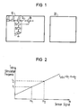
- FIG 1 is a functional block diagram of a rate-responsive pacemaker.
- FIG 2 is a graph illustrating the linear relationship between sensor signal and stimulation frequency.
- In FIG 1 the pacemaker is generally designated 10. A
force sensor 11 is included in the pacemaker can. it should be noted here that also other sensor types and also other sensor placements could be used. The sensor signal is transformed in an A/D-converter block 12 into a signal m with a pulse duration proportional to the amplitude of the original sensor signal. Subsequently, the rate responsive parameters defining the constants of the function relating the sensor signal to the stimulation frequency, fstim, are introduced in aparameter block 13.Block 13 is under the control of a logic and timing block 15, also controlling other functions of the pacemaker (e.g. output block 18), which, except for the rate responsive part, is a convential demand pacemaker. - Switch 14, enables a passive mode for the rate responsive function, viz. the pacemaker operates at the programmed minimum rate, while the rate which would have been present with switch 14 closed is still indicated from
sensor 11. - The program memory 16 enables the programming signal and the calculated parameter values to be stored. That signal contains i.e. the desired stimulation frequency and is received from the
programmer 30 through telemetry circuitry 17. The parameter calculating unit could either be contained in block 15 orprogrammer 30. - The setting of the rate responsive parameters is now described in connection with FIG 2. In FIG 2 a linear function (fstim = k₁ · m + k₂ with k₁ and k₂ representing slope and threshold respectively) between sensor signal m and stimulation frequency is illustrated.
- First, the patient is exposed to a low work load, for instance slow walking. This work load is correlated with a range of stimulation frequencies, e.g. 70 - 90 pulses per minute. The physician selects from this range one frequency f₁ appearing to be desirable to the individual pacemaker patient. The same level of work load corresponds to a sensor signal value m₁ indicative of said work load, which value is obtained from the pacemaker sensor.
- Second a repetition of the above measures is carried out for another work load, for instance fast walking. This work load is correlated with another range of stimulation frequencies, e.g. 130 - 150 and the physician selects also here a desireable frequency, f₂. The corresponding sensor signal value is m₂.
- The rate responsive parameters k₁ and k₂ can now be calculated either in the pacemaker circuitry or in the programmer by inserting m₁, m₂ and f₁, f₂ into the function. Thus, in accordance with the described method, slope and threshold are set in a way where the physician is only confronted with desired stimulation frequencies.
- In case of a dependency between sensor signal for different work loads of the type described previously, viz. m₂ = m₂ + C₁ (C₁ = constant) only one stimulation frequency f₁ need to be selected, as the parameters can now be calculated from f₁, m₁ and the above dependency.
- In a non-linear relationship of the exponential or logaritmic type, where the function also includes two parameters the same way of parameter setting applies, viz. for different work loads the values m₁, m₂ and f₁, f₂ are established and inserted into the function. Also here the dependency m₂ = m₁ + constant may occur and is handled as in the linear case just described.
- The invention has been described for a heart pacemaker just by way of example, and it should be noted that it applies to any implantable physiological stimulating device with a similar relationship between sensor signal and stimulation frequency.
Claims (6)
Applications Claiming Priority (2)
| Application Number | Priority Date | Filing Date | Title |
|---|---|---|---|
| SE8702523 | 1987-06-17 | ||
| SE8702523A SE8702523D0 (en) | 1987-06-17 | 1987-06-17 | RATE RESPONSIVE PACEMAKER |
Publications (3)
| Publication Number | Publication Date |
|---|---|
| EP0299208A2 true EP0299208A2 (en) | 1989-01-18 |
| EP0299208A3 EP0299208A3 (en) | 1991-01-23 |
| EP0299208B1 EP0299208B1 (en) | 1993-09-01 |
Family
ID=20368891
Family Applications (1)
| Application Number | Title | Priority Date | Filing Date |
|---|---|---|---|
| EP88109322A Expired - Lifetime EP0299208B1 (en) | 1987-06-17 | 1988-06-10 | Rate responsive pacemaker |
Country Status (5)
| Country | Link |
|---|---|
| US (1) | US4922907A (en) |
| EP (1) | EP0299208B1 (en) |
| JP (1) | JPS6417660A (en) |
| DE (1) | DE3883651T2 (en) |
| SE (1) | SE8702523D0 (en) |
Cited By (5)
| Publication number | Priority date | Publication date | Assignee | Title |
|---|---|---|---|---|
| EP0324598A2 (en) * | 1988-01-14 | 1989-07-19 | Stuart Charles Webb | Rate-responsive pacemaker |
| EP0449401A2 (en) * | 1990-03-08 | 1991-10-02 | Cardiac Pacemakers, Inc. | Variation in cardiac chamber volume or pressure as a controlling parameter |
| EP0452732A2 (en) * | 1990-04-16 | 1991-10-23 | Pacesetter, Inc. | Rate-responsive pacemaker with circuitry for processing multiple sensor inputs |
| US5303702A (en) * | 1990-12-27 | 1994-04-19 | Ela Medical | Automatic adjustment of the control function for a rate adaptive pacemaker |
| DE4447447A1 (en) * | 1994-12-29 | 1996-07-11 | Pacesetter Ab | Device for determining the physical stress for pacemakers |
Families Citing this family (23)
| Publication number | Priority date | Publication date | Assignee | Title |
|---|---|---|---|---|
| US5080096A (en) * | 1990-07-06 | 1992-01-14 | Medtronic, Inc. | Method and apparatus for accessing a nonvolatile memory |
| US5370667A (en) * | 1992-04-03 | 1994-12-06 | Intermedics, Inc. | Device and method for automatically adjusting tachycardia recognition criteria based on detected parameter |
| US5282839A (en) * | 1992-12-14 | 1994-02-01 | Medtronic, Inc. | Rate responsive cardiac pacemaker and method for providing an optimized pacing rate which varies with a patient's physiologic demand |
| US5330512A (en) * | 1992-12-28 | 1994-07-19 | Cardiac Pacemakers, Inc. | Electrode charge-neutral sensing of evoked ECG |
| US7110817B2 (en) * | 1998-05-08 | 2006-09-19 | Cardiac Pacemakers, Inc. | Method and apparatus for optimizing ventricular synchrony during DDD resynchronization therapy using adjustable atrio-ventricular delays |
| US6144880A (en) * | 1998-05-08 | 2000-11-07 | Cardiac Pacemakers, Inc. | Cardiac pacing using adjustable atrio-ventricular delays |
| US7158830B2 (en) * | 1998-05-08 | 2007-01-02 | Cardiac Pacemakers, Inc. | Method and apparatus for optimizing stroke volume during DDD resynchronization therapy using adjustable atrio-ventricular delays |
| US6597951B2 (en) * | 2001-03-16 | 2003-07-22 | Cardiac Pacemakers, Inc. | Automatic selection from multiple cardiac optimization protocols |
| US6832113B2 (en) | 2001-11-16 | 2004-12-14 | Cardiac Pacemakers, Inc. | Non-invasive method and apparatus for cardiac pacemaker pacing parameter optimization and monitoring of cardiac dysfunction |
| US6973349B2 (en) | 2001-12-05 | 2005-12-06 | Cardiac Pacemakers, Inc. | Method and apparatus for minimizing post-infarct ventricular remodeling |
| US7206634B2 (en) * | 2002-07-26 | 2007-04-17 | Cardiac Pacemakers, Inc. | Method and apparatus for optimizing cardiac pumping performance |
| US7123962B2 (en) * | 2002-12-02 | 2006-10-17 | Cardiac Pacemakers, Inc. | Phonocardiographic image-based atrioventricular delay optimization |
| US7013176B2 (en) * | 2003-01-28 | 2006-03-14 | Cardiac Pacemakers, Inc. | Method and apparatus for setting pacing parameters in cardiac resynchronization therapy |
| US9002452B2 (en) | 2003-11-07 | 2015-04-07 | Cardiac Pacemakers, Inc. | Electrical therapy for diastolic dysfunction |
| US7184835B2 (en) * | 2003-12-12 | 2007-02-27 | Cardiac Pacemakers, Inc. | Method and apparatus for adjustable AVD programming using a table |
| US7123960B2 (en) | 2003-12-22 | 2006-10-17 | Cardiac Pacemakers, Inc. | Method and system for delivering cardiac resynchronization therapy with variable atrio-ventricular delay |
| US7215997B2 (en) * | 2003-12-22 | 2007-05-08 | Cardiac Pacemakers, Inc. | Dynamic device therapy control for treating post myocardial infarction patients |
| US7676261B2 (en) * | 2004-09-30 | 2010-03-09 | General Electric Company | Method and system for enhancing pace pulses |
| US8108034B2 (en) | 2005-11-28 | 2012-01-31 | Cardiac Pacemakers, Inc. | Systems and methods for valvular regurgitation detection |
| US8046069B2 (en) | 2005-12-22 | 2011-10-25 | Cardiac Pacemakers, Inc. | Method and apparatus for control of cardiac therapy using non-invasive hemodynamic sensor |
| US7869871B2 (en) | 2006-03-31 | 2011-01-11 | Cardiac Pacemakers, Inc. | Pacing therapy for diastolic heart failure |
| US8521278B2 (en) * | 2008-05-08 | 2013-08-27 | Cardiac Pacemakers, Inc. | Smart delay for intermittent stress therapy |
| EP2599523B1 (en) | 2011-11-30 | 2016-02-10 | St. Jude Medical AB | Activity-responsive pacing |
Citations (7)
| Publication number | Priority date | Publication date | Assignee | Title |
|---|---|---|---|---|
| EP0133828A1 (en) * | 1983-08-02 | 1985-03-06 | BIOVALLEES Société Anonyme: | Method of controlling a cardiac pacemaker |
| EP0140472A1 (en) * | 1983-06-30 | 1985-05-08 | Medtronic, Inc. | Stroke volume controlled pacer |
| EP0178528A1 (en) * | 1984-10-18 | 1986-04-23 | Telectronics N.V. | Method for adjusting heart/pacer rate relative to right ventricular systolic pressure to obtain a required cardiac output |
| EP0203027A1 (en) * | 1985-02-22 | 1986-11-26 | BIOTRONIK Mess- und Therapiegeräte GmbH & Co Ingenieurbüro Berlin | Requirement heart pacemaker with physiological control |
| EP0225839A1 (en) * | 1985-09-17 | 1987-06-16 | BIOTRONIK Mess- und Therapiegeräte GmbH & Co Ingenieurbüro Berlin | Heart pacemaker |
| US4726383A (en) * | 1982-05-19 | 1988-02-23 | Purdue Research Foundation | Exercise-responsive cardiac pacemaker lead |
| US4730619A (en) * | 1985-04-11 | 1988-03-15 | Telectronics, N.V. | Apparatus and method for adjusting heart/pacer rate relative to ejection time to obtain a required cardiac output |
Family Cites Families (3)
| Publication number | Priority date | Publication date | Assignee | Title |
|---|---|---|---|---|
| US4428378A (en) * | 1981-11-19 | 1984-01-31 | Medtronic, Inc. | Rate adaptive pacer |
| EP0151689B1 (en) * | 1984-02-07 | 1990-12-27 | SCHIAPPARELLI MEDTRONIC S.p.A. | Minute ventilation dependent rate responsive pacer |
| US4803987A (en) * | 1986-06-11 | 1989-02-14 | Intermedics, Inc. | Temperature responsive controller for cardiac pacer |
-
1987
- 1987-06-17 SE SE8702523A patent/SE8702523D0/en unknown
-
1988
- 1988-06-10 DE DE88109322T patent/DE3883651T2/en not_active Expired - Fee Related
- 1988-06-10 EP EP88109322A patent/EP0299208B1/en not_active Expired - Lifetime
- 1988-06-10 US US07/205,333 patent/US4922907A/en not_active Expired - Lifetime
- 1988-06-15 JP JP63147916A patent/JPS6417660A/en active Pending
Patent Citations (7)
| Publication number | Priority date | Publication date | Assignee | Title |
|---|---|---|---|---|
| US4726383A (en) * | 1982-05-19 | 1988-02-23 | Purdue Research Foundation | Exercise-responsive cardiac pacemaker lead |
| EP0140472A1 (en) * | 1983-06-30 | 1985-05-08 | Medtronic, Inc. | Stroke volume controlled pacer |
| EP0133828A1 (en) * | 1983-08-02 | 1985-03-06 | BIOVALLEES Société Anonyme: | Method of controlling a cardiac pacemaker |
| EP0178528A1 (en) * | 1984-10-18 | 1986-04-23 | Telectronics N.V. | Method for adjusting heart/pacer rate relative to right ventricular systolic pressure to obtain a required cardiac output |
| EP0203027A1 (en) * | 1985-02-22 | 1986-11-26 | BIOTRONIK Mess- und Therapiegeräte GmbH & Co Ingenieurbüro Berlin | Requirement heart pacemaker with physiological control |
| US4730619A (en) * | 1985-04-11 | 1988-03-15 | Telectronics, N.V. | Apparatus and method for adjusting heart/pacer rate relative to ejection time to obtain a required cardiac output |
| EP0225839A1 (en) * | 1985-09-17 | 1987-06-16 | BIOTRONIK Mess- und Therapiegeräte GmbH & Co Ingenieurbüro Berlin | Heart pacemaker |
Cited By (12)
| Publication number | Priority date | Publication date | Assignee | Title |
|---|---|---|---|---|
| EP0324598A2 (en) * | 1988-01-14 | 1989-07-19 | Stuart Charles Webb | Rate-responsive pacemaker |
| EP0324598A3 (en) * | 1988-01-14 | 1990-01-31 | Stuart Charles Webb | Rate-responsive pacemaker |
| EP0449401A2 (en) * | 1990-03-08 | 1991-10-02 | Cardiac Pacemakers, Inc. | Variation in cardiac chamber volume or pressure as a controlling parameter |
| EP0449401A3 (en) * | 1990-03-08 | 1991-10-16 | Cardiac Pacemakers, Inc. | Variation in cardiac chamber volume or pressure as a controlling parameter |
| US5137019A (en) * | 1990-03-08 | 1992-08-11 | Cardiac Pacemakers, Inc. | Variation in cardiac chamber volume or pressure as a controlling parameter |
| US5391190A (en) * | 1990-03-08 | 1995-02-21 | Cardiac Pacemakers, Inc. | Variation in cardiac chamber volume or pressure as a controlling parameter |
| EP0452732A2 (en) * | 1990-04-16 | 1991-10-23 | Pacesetter, Inc. | Rate-responsive pacemaker with circuitry for processing multiple sensor inputs |
| EP0452732A3 (en) * | 1990-04-16 | 1993-02-03 | Siemens Elema Ab | Rate-responsive pacemaker with circuitry for processing multiple sensor inputs |
| US5303702A (en) * | 1990-12-27 | 1994-04-19 | Ela Medical | Automatic adjustment of the control function for a rate adaptive pacemaker |
| DE4447447A1 (en) * | 1994-12-29 | 1996-07-11 | Pacesetter Ab | Device for determining the physical stress for pacemakers |
| US5645575A (en) * | 1994-12-29 | 1997-07-08 | Pacestetter Ab | Cardiac pacemaker and pacing method using detection of physical stress for adjusting stimulation rate |
| DE4447447C2 (en) * | 1994-12-29 | 2000-07-06 | Pacesetter Ab Jaerfaella | Pacemaker |
Also Published As
| Publication number | Publication date |
|---|---|
| US4922907A (en) | 1990-05-08 |
| EP0299208B1 (en) | 1993-09-01 |
| SE8702523D0 (en) | 1987-06-17 |
| EP0299208A3 (en) | 1991-01-23 |
| DE3883651D1 (en) | 1993-10-07 |
| JPS6417660A (en) | 1989-01-20 |
| DE3883651T2 (en) | 1994-03-24 |
Similar Documents
| Publication | Publication Date | Title |
|---|---|---|
| EP0299208B1 (en) | Rate responsive pacemaker | |
| EP0593745B1 (en) | Work-modulated pacing rate deceleration | |
| US5226413A (en) | Rate responsive pacemaker and method for automatically initializing the same | |
| US5158078A (en) | Rate responsive pacemaker and methods for optimizing its operation | |
| AU681427B2 (en) | Multi-sensor blending in a rate responsive cardiac pacemaker | |
| EP0545971B1 (en) | Pacemaker with optimized rate responsiveness | |
| EP0249820B1 (en) | A cardiac pacer for pacing a human heart | |
| EP0431083B1 (en) | Pacemaker having automatic rate response adjustment | |
| US4901725A (en) | Minute volume rate-responsive pacemaker | |
| US5040534A (en) | Microprocessor controlled rate-responsive pacemaker having automatic rate response threshold adjustment | |
| EP0324598B1 (en) | Rate-responsive pacemaker | |
| US20030176899A1 (en) | Programming system for medical devices | |
| US4870968A (en) | System and method for controlling the stimulation frequency of heart pacemakers | |
| EP0543925B1 (en) | Rate responsive pacemaker | |
| EP0759313A2 (en) | Device for varying the threshold detection level of a sensor | |
| US5470344A (en) | Rate responsive pacemake with improved rate change dynamics and pacing method | |
| US5271396A (en) | Activity controlled pacer with automatic sensor response amplification adjustment | |
| EP0804940A2 (en) | Rate-responsive pacemaker with automatic rate response factor selection | |
| EP0861677B1 (en) | Pacemaker with improved hysteresis |
Legal Events
| Date | Code | Title | Description |
|---|---|---|---|
| PUAI | Public reference made under article 153(3) epc to a published international application that has entered the european phase |
Free format text: ORIGINAL CODE: 0009012 |
|
| AK | Designated contracting states |
Kind code of ref document: A2 Designated state(s): DE FR GB IT NL SE |
|
| PUAL | Search report despatched |
Free format text: ORIGINAL CODE: 0009013 |
|
| AK | Designated contracting states |
Kind code of ref document: A3 Designated state(s): DE FR GB IT NL SE |
|
| 17P | Request for examination filed |
Effective date: 19910409 |
|
| 17Q | First examination report despatched |
Effective date: 19920930 |
|
| GRAA | (expected) grant |
Free format text: ORIGINAL CODE: 0009210 |
|
| AK | Designated contracting states |
Kind code of ref document: B1 Designated state(s): DE FR GB IT NL SE |
|
| PG25 | Lapsed in a contracting state [announced via postgrant information from national office to epo] |
Ref country code: SE Effective date: 19930901 |
|
| REF | Corresponds to: |
Ref document number: 3883651 Country of ref document: DE Date of ref document: 19931007 |
|
| ITF | It: translation for a ep patent filed |
Owner name: STUDIO JAUMANN |
|
| ET | Fr: translation filed | ||
| PLBE | No opposition filed within time limit |
Free format text: ORIGINAL CODE: 0009261 |
|
| STAA | Information on the status of an ep patent application or granted ep patent |
Free format text: STATUS: NO OPPOSITION FILED WITHIN TIME LIMIT |
|
| 26N | No opposition filed | ||
| ITPR | It: changes in ownership of a european patent |
Owner name: CESSIONE;PACESETTER AB |
|
| REG | Reference to a national code |
Ref country code: GB Ref legal event code: 732E |
|
| REG | Reference to a national code |
Ref country code: FR Ref legal event code: TP |
|
| NLS | Nl: assignments of ep-patents |
Owner name: PACESETTER AB |
|
| PGFP | Annual fee paid to national office [announced via postgrant information from national office to epo] |
Ref country code: GB Payment date: 19980515 Year of fee payment: 11 |
|
| PG25 | Lapsed in a contracting state [announced via postgrant information from national office to epo] |
Ref country code: GB Free format text: LAPSE BECAUSE OF NON-PAYMENT OF DUE FEES Effective date: 19990610 |
|
| PGFP | Annual fee paid to national office [announced via postgrant information from national office to epo] |
Ref country code: NL Payment date: 19990621 Year of fee payment: 12 |
|
| GBPC | Gb: european patent ceased through non-payment of renewal fee |
Effective date: 19990610 |
|
| PG25 | Lapsed in a contracting state [announced via postgrant information from national office to epo] |
Ref country code: NL Free format text: LAPSE BECAUSE OF NON-PAYMENT OF DUE FEES Effective date: 20010101 |
|
| NLV4 | Nl: lapsed or anulled due to non-payment of the annual fee |
Effective date: 20010101 |
|
| PGFP | Annual fee paid to national office [announced via postgrant information from national office to epo] |
Ref country code: DE Payment date: 20060628 Year of fee payment: 19 |
|
| PGFP | Annual fee paid to national office [announced via postgrant information from national office to epo] |
Ref country code: IT Payment date: 20060630 Year of fee payment: 19 Ref country code: FR Payment date: 20060630 Year of fee payment: 19 |
|
| REG | Reference to a national code |
Ref country code: FR Ref legal event code: ST Effective date: 20080229 |
|
| PG25 | Lapsed in a contracting state [announced via postgrant information from national office to epo] |
Ref country code: DE Free format text: LAPSE BECAUSE OF NON-PAYMENT OF DUE FEES Effective date: 20080101 |
|
| PG25 | Lapsed in a contracting state [announced via postgrant information from national office to epo] |
Ref country code: FR Free format text: LAPSE BECAUSE OF NON-PAYMENT OF DUE FEES Effective date: 20070702 |
|
| PG25 | Lapsed in a contracting state [announced via postgrant information from national office to epo] |
Ref country code: IT Free format text: LAPSE BECAUSE OF NON-PAYMENT OF DUE FEES Effective date: 20070610 |