EP0301169A1 - Fluid treatment - Google Patents
Fluid treatment Download PDFInfo
- Publication number
- EP0301169A1 EP0301169A1 EP88104631A EP88104631A EP0301169A1 EP 0301169 A1 EP0301169 A1 EP 0301169A1 EP 88104631 A EP88104631 A EP 88104631A EP 88104631 A EP88104631 A EP 88104631A EP 0301169 A1 EP0301169 A1 EP 0301169A1
- Authority
- EP
- European Patent Office
- Prior art keywords
- chamber
- water
- carbonation
- concentrate
- carbon dioxide
- Prior art date
- Legal status (The legal status is an assumption and is not a legal conclusion. Google has not performed a legal analysis and makes no representation as to the accuracy of the status listed.)
- Withdrawn
Links
Images


Classifications
-
- B—PERFORMING OPERATIONS; TRANSPORTING
- B67—OPENING, CLOSING OR CLEANING BOTTLES, JARS OR SIMILAR CONTAINERS; LIQUID HANDLING
- B67D—DISPENSING, DELIVERING OR TRANSFERRING LIQUIDS, NOT OTHERWISE PROVIDED FOR
- B67D1/00—Apparatus or devices for dispensing beverages on draught
- B67D1/0042—Details of specific parts of the dispensers
- B67D1/0057—Carbonators
- B67D1/0069—Details
- B67D1/0074—Automatic carbonation control
- B67D1/0075—Automatic carbonation control by sensing gas pressure
-
- B—PERFORMING OPERATIONS; TRANSPORTING
- B01—PHYSICAL OR CHEMICAL PROCESSES OR APPARATUS IN GENERAL
- B01F—MIXING, e.g. DISSOLVING, EMULSIFYING OR DISPERSING
- B01F23/00—Mixing according to the phases to be mixed, e.g. dispersing or emulsifying
- B01F23/20—Mixing gases with liquids
- B01F23/23—Mixing gases with liquids by introducing gases into liquid media, e.g. for producing aerated liquids
- B01F23/234—Surface aerating
- B01F23/2342—Surface aerating with stirrers near to the liquid surface, e.g. partially immersed, for spraying the liquid in the gas or for sucking gas into the liquid, e.g. using stirrers rotating around a horizontal axis or using centrifugal force
-
- B—PERFORMING OPERATIONS; TRANSPORTING
- B01—PHYSICAL OR CHEMICAL PROCESSES OR APPARATUS IN GENERAL
- B01F—MIXING, e.g. DISSOLVING, EMULSIFYING OR DISPERSING
- B01F23/00—Mixing according to the phases to be mixed, e.g. dispersing or emulsifying
- B01F23/20—Mixing gases with liquids
- B01F23/23—Mixing gases with liquids by introducing gases into liquid media, e.g. for producing aerated liquids
- B01F23/236—Mixing gases with liquids by introducing gases into liquid media, e.g. for producing aerated liquids specially adapted for aerating or carbonating beverages
- B01F23/2363—Mixing systems, i.e. flow charts or diagrams; Arrangements, e.g. comprising controlling means
-
- B—PERFORMING OPERATIONS; TRANSPORTING
- B67—OPENING, CLOSING OR CLEANING BOTTLES, JARS OR SIMILAR CONTAINERS; LIQUID HANDLING
- B67D—DISPENSING, DELIVERING OR TRANSFERRING LIQUIDS, NOT OTHERWISE PROVIDED FOR
- B67D1/00—Apparatus or devices for dispensing beverages on draught
- B67D1/0042—Details of specific parts of the dispensers
- B67D1/0043—Mixing devices for liquids
- B67D1/0044—Mixing devices for liquids for mixing inside the dispensing nozzle
- B67D1/0046—Mixing chambers
- B67D1/0047—Mixing chambers with movable parts, e.g. for stirring
-
- B—PERFORMING OPERATIONS; TRANSPORTING
- B67—OPENING, CLOSING OR CLEANING BOTTLES, JARS OR SIMILAR CONTAINERS; LIQUID HANDLING
- B67D—DISPENSING, DELIVERING OR TRANSFERRING LIQUIDS, NOT OTHERWISE PROVIDED FOR
- B67D1/00—Apparatus or devices for dispensing beverages on draught
- B67D1/0042—Details of specific parts of the dispensers
- B67D1/0057—Carbonators
- B67D1/0069—Details
- B67D1/0071—Carbonating by injecting CO2 in the liquid
-
- B—PERFORMING OPERATIONS; TRANSPORTING
- B01—PHYSICAL OR CHEMICAL PROCESSES OR APPARATUS IN GENERAL
- B01F—MIXING, e.g. DISSOLVING, EMULSIFYING OR DISPERSING
- B01F27/00—Mixers with rotary stirring devices in fixed receptacles; Kneaders
- B01F27/60—Mixers with rotary stirring devices in fixed receptacles; Kneaders with stirrers rotating about a horizontal or inclined axis
-
- Y—GENERAL TAGGING OF NEW TECHNOLOGICAL DEVELOPMENTS; GENERAL TAGGING OF CROSS-SECTIONAL TECHNOLOGIES SPANNING OVER SEVERAL SECTIONS OF THE IPC; TECHNICAL SUBJECTS COVERED BY FORMER USPC CROSS-REFERENCE ART COLLECTIONS [XRACs] AND DIGESTS
- Y10—TECHNICAL SUBJECTS COVERED BY FORMER USPC
- Y10S—TECHNICAL SUBJECTS COVERED BY FORMER USPC CROSS-REFERENCE ART COLLECTIONS [XRACs] AND DIGESTS
- Y10S261/00—Gas and liquid contact apparatus
- Y10S261/07—Carbonators
Definitions
- This invention relates to fluid treatment. More particularly, the invention concerns apparatus and method for carbonating water and/or for dispensing flavoured drinks, especially carbonated drinks.
- Both Schwendimann and Peters provide injectors which are rotatable and which have laterally directed members at their bottom end to assist in the mixing of the carbon dioxide gas with the water.
- the main problem with the injection method of carbonation is that it is only effective if relatively high pressures are used so that, during carbonation, the carbonation chamber is pressurized to a relatively high level. Typically, for example, pressures of 170 psig (11.6 bars) may be involved.
- the second group of known methods for achieving carbonation involves spraying or atomizing the water in an atmosphere of carbon dioxide gas.
- a carbonation chamber may be prefilled with carbon dioxide gas and the water introduced into the chamber by spraying.
- the water may be drawn upwardly and sprayed into the carbon dioxide atmosphere above the water level in the chamber.
- carbon dioxide is dissolved into the water droplets in the spray and the droplets carry the carbon dioxide in dissolved form into the body of the water to effect carbonation.
- Typical proposals for achieving carbonation by this method are disclosed in US patent No.2,306,714 (Rowell) and US patent No.2,391,003 (Bowman).
- a major problem with these methods also is that they require the carbonation chamber to be pressurized to a relatively high level similar to that mentioned above. Also these methods are slow, so that a long time is required to achieve an adequate degree of carbonation.
- One of the objects of the present invention is to provide an improved method and apparatus for carbonation.
- a carbonation method in which a carbonation chamber is partly filled with water and an atmosphere comprising carbon dioxide is provided above the level of water in the chamber, the method comprising continuously or repeatedly drawing or forcing gas from said atmosphere down into the water.
- the invention provides carbonation apparatus comprising a carbonation chamber adapted to be partially filled with water and to contain an atmosphere comprising carbon dioxide above the level of water in the chamber, and means for continuously or repeatedly drawing or forcing gas from said atmosphere down into said water.
- the invention provides carbonation apparatus comprising a carbonation chamber adapted to be partially filled with water and to contain an atmosphere including carbon dioxide in the space above said water, and a movable member, preferable a rotatable member, which in operation moves repeatedly between said atmosphere and said water so as to cause gas from said atmosphere to be moved downwardly into said water.
- the present invention provides carbonation apparatus comprising a carbonation chamber adapted to be partially filled with water and to contain an atmosphere including carbon dioxide gas in a space above the water, and a member which is rotatable about a non-vertical axis and has a plurality of vanes.
- the axis of rotation is horizontal.
- the liquid in the chamber will be swept around, and in contact with, the cylindrical internal wall of the chamber. Accordingly, there will be no discernable CO2 atmosphere above the water in the chamber and the vanes of the rotor will not function to force CO2 from an atmosphere thereof down into the water as in a preferred form of the present invention. Further, in Knedlik the rotor is driven continuously both when the apparatus is in the "idling" state and when beverage is being discharged, at which time the liquid in the chamber is simultaneously replenished to keep the chamber full.
- the carbonation process is stopped prior to discharge of the carbonated liquid, the chamber being emptied at this point, because agitation of the liquid as it is leaving the chamber would tend to cause de-carbonation.
- the Knedlik apparatus is intended for commercial use in which continuously available beverage is provided and is not suitable for home use in view of its complexity and high cost. Applicants also acknowledge that Knedlik states that CO2 and water might be introduced via separate conduits into his chamber but even with this modification the function of the rotor in Knedlik will not be changed and there will be no discernable CO2 atmosphere above the water level.
- carbonated drinks are mixed with a flavoured concentrate (syrup).
- carbonation apparatus in addition to being provided with means for carbonating water, should also be provided with means for dispensing a selected concentrate and mixing that concentrate with the carbonated water.
- a known method of dispensing the concentrate involves supplying the vessel containing the concentrate with carbon dioxide under pressure from the carbon dioxide supply tank so that a required quantity of concentrate is forced out of the container to a dispensing nozzle from which it may be discharged into a glass for mixing with the carbonated water.
- US patent No.2,391,003 (Bowman) illustrates this method.
- the disadvantage of the method is that carbon dioxide is wasted.
- the invention is concerned with an improved method of dispensing concentrate.
- carbonation apparatus comprises a carbonation chamber for receiving water and carbon dioxide gas and concentrate dispensing means which utilizes gas from the carbonation chamber, after a carbonation operation, for causing a movement of said concentrate to enable said concentrate to be dispensed.
- said concentrate is moved directly from a concentrate container to a discharge nozzle under said pressure of gas from said carbonation chamber.
- the invention provides a carbonation method and apparatus in which, to achieve carbonation, a carbonation chamber is pressurized and in which the pressure in said carbonation chamber is utilized to cause movement of concentrate towards a dispensing nozzle.
- the upper part of the carbonation chamber is connected to an upper part of a concentrate container through a valve so that, upon opening of the valve, the concentrate container becomes pressurized.
- concentrate may be dispensed without wasting fresh carbon dioxide i.e. carbon dioxide direct from the carbon dioxide tank.
- carbonation apparatus should include a number of concentrate containers for containing respectively concentrates of different flavours.
- the containers are connected to outlet orifices for the discharge of the concentrate via electro-magnetically operated valves. Selection is made by actuating the appropriate valve.
- electro-magnetically operated valves Such arrangements are relatively expensive.
- a concentrate selector arrangement comprises a number of valves, a manually movable member for effecting selection, and mechanical means for actuating the valve according to the position of the selector member.
- the selector member or a part thereof is utilized to transmit movement from an actuating member to the selected valve.
- the actuating member may be so arranged that when a glass is positioned to receive carbonated water and concentrate, the actuator member is operated to cause dispensing.
- a carbonated drink dispensing device comprises an actuating member which upon movement opens both a first valve for the discharge of carbonated water and a selected one of a plurality of further valves for the discharge of a selected concentrate, a movable selector member being provided for selecting the further valve to be opened.
- the selector member is attached to a part of the first valve so that the first valve and the selected further valve are opened at approximately the same time.
- Concentrates of different flavour generally have different viscosities and accordingly there is need to control the quantity of concentrate dispensed.
- the present invention provides, in a further preferred aspect, a carbonation apparatus capable of dispensing selectively different ones of a plurality of concentrates, the means for dispensing the concentrates including different conduits for transporting the concentrates from respective concentrate containers to a discharge point, at least one of said conduits having a bore of different cross-sectional area to the other or at least one of the others to compensate for differences in viscosity between the concentrates.
- the carbonation apparatus comprises a carbonation chamber 10, a water supply tank 12, a carbon dioxide supply tank 14 and concentrate supply arrangement 16.
- a valve unit 18 is disposed on the bottom of the chamber 10 for dispensing both carbonated water from the chamber 10 and a selected concentrate from the arrangement 16 into a glass 20.
- Water is supplied from the tank 12 to the chamber 10 through a valve V2 controlled by a solenoid S2, a conduit 22 and a ball valve 24 located inside the chamber 10.
- a vent 26 connected to the interior of the chamber 10 by means of a pipe 28 permits air in the chamber 10 to be vented to atmosphere while the chamber 10 is being filled with water.
- the pipe 28 projects down into the chamber 10 a distance which is such that its lower end is imersed in the water when the chamber 10 has been filled with water to the required level indicated by W.
- Carbon dioxide is supplied from container 14 through valve V1, controlled by a solenoid S1, and a conduit 30 leading into the chamber 10 at the top.
- a ball 29 located in the vent 26 is arranged to close the vent if water is forced up the pipe 28 due to pressurization of the chamber.
- the ball is movable upwardly into sealing engagement with a valve seat 31 at the top of the vent.
- the ball 29 is also arranged so that it closes the vent, in response to increasing gas pressure in the chamber 10, if carbon dioxide is introduced into the chamber 10 with the water level below the lower end of the pipe 28 so that carbonation may be achieved in these circumstances.
- a paddle 32 is mounted inside the chamber 10 for rotation about a horizontal axis, being carried on the shaft 34 of a motor 36 which is mounted on the outside of the chamber 10.
- the shaft 34 may project through an opening (not shown) in the wall of the chamber 10 with an appropriate seal being provided.
- the shaft 34 could be connected to the motor 36 by a magnetic coupling.
- the paddle 32 comprises three pairs of vanes 38a, 38b; 40a, 40b and 42a, 42b.
- the two vanes of each pair (e.g. 38a and 38b) are mounted directly opposite each other on the shaft 34.
- the vanes 40a and 40b are mounted on the shaft 34 to one side of the vanes 38a and 38b and at a different angle relative thereto; and the vanes 42a and 42b are mounted on the shaft 34 at the other side of the vanes 38a and 38b and again at a different angle to the other vanes. These angles are such that the six vanes are equi-angularly spaced around the shaft 34.
- the anglar position of the shaft 34 shown in Figs.
- L indicates the length of the portion of each vane which projects above the water level W when the vane is in its uppermost position with the paddle stationary and the apparatus horizontal and D indicates the diameter of the circle swept by the tip of each vane as the paddle rotates.
- L should be at least 5% of D and preferably greater than 12% of D. It is particularly preferred that L should be from 12% to 15% of D for achieving optimum carbonation.
- the chamber 10 is partially filled with water up to the level W. Thereafter, carbon dioxide is admitted to the space above the level of water in the chamber 10 by opening the valve V1.
- a pressure switch 44 senses the gas pressure in the chamber 10. When this reaches the required level preferably in the range 60 to 140 psig (9.6 bars), for example 100 psig (6.8 bar), the solenoid is actuated to close the valve V1.
- the ball valve 24 prevents water being forced back up the conduit 22 due to the pressure in the chamber 10.
- the motor 36 is energized to cause the paddle 32 to rotate. Typically, this rotation may be at a speed from 500 to 2000 rpm, preferably within the range 1000 to 1500 rpm.
- This rotation is continued for several seconds, for example 5 seconds, during which carbonation of the water takes place.
- the degree of carbonation may be varied by varying the time for which the paddle is driven and/or by varying the pressure of the atmosphere containing carbon dioxide in the space in the chamber 10 above the water level.
- the action of the paddle is to force the gas in the space above the water level down into the water. As much gas as possible should be forced into the water and it should be carried to a level which is as deep as possible.
- the vanes are dimensioned, as discussed above, such that they reach nearly to the top and nearly to the bottom of the chamber 10. Also, therefore, the paddle acts to shift water from the bottom portion of the chamber 10 to a higher level so that water at all levels may be uniformly carbonated. Further, the paddle creates intense agitation of the water causing it to be splashed up into the atmosphere of carbon dioxide thereby to assist with carbonation and thereby also achieving uniform carbonation. As can be seen in Fig.
- each vane in addition to forcing carbon dioxide in gaseous form in front of it into the water, creates a vortex behind it which draws carbon dioxide in gaseous form in and causes the gas to be carried down into the water.
- Fig. 3 shows the fluid flow lines created by the vane as it moves. It can be seen from Fig. 1, that the paddle 32 is located to one side of the chamber 10, which is preferably of circular cross-section as seen in plan view. With this arrangement, the water in the chamber 10 is also caused to rotate around the chamber 10 so that, as the paddle is driven, different portions of the body of water in the chamber 10 move past the paddle to be subjected to the carbonation action.
- the concentrate dispensing arrangement 16 comprises three containers 46, 48 and 50 containing concentrates of different flavours. Dip tubes 52, 54 and 56 extend into the respective containers 46, 48 and 50 almost to the bottom and are connected via respective conduits 58, 60 and 62 to the valve unit 18 for supplying concentrate from the containers to the valve unit.
- the upper part of each of the containers 46, 48 and 50 is connected by a conduit arrangement 64 to the upper part of the chamber 10.
- a valve V3 is located in the conduit arrangement 64 and is controlled by the solenoid S2. After completion of the carbonation operation in the chamber 10, the valve V3 is opened to permit the upper parts of the containers 46, 48 and 50 to be pressurized utilizing the gas in the upper part of the chamber 10.
- a pressure relief valve 66 connected to the conduit arrangement 64 limits the pressurization of the containers 46, 48 and 50 to a predetermined value, say 2 psig (0.1 bars).
- a predetermined value say 2 psig (0.1 bars).
- each of the containers 46, 48 and 50 is pressurized to the same value and this pressurization exerts a force on the concentrate in the containers which is sufficient to dispense each concentrate from its respective container. Since concentrates have different viscosities, the bore of the dip tubes 55, 54 and 56 and/or that of the conduits 58, 60, 62 is selected to ensure that the required amount of concentrate will be dispensed.
- the bore of the dip tube and connecting conduit may be 6 mm, if lemonade is to be dispensed it may be 3mm, if tonic is to be dispensed it may be 3mm also.
- the valve unit 18 provides three functions. First, it relieves the pressure in the carbonation chamber 10. Second, it permits selection of which of the concentrates from the containers 46, 48 and 50 is to be dispensed and it dispenses the selected concentrate. Third, it dispenses carbonated water from the chamber 10.
- the valve unit 18 For relieving the pressure in the carbonation chamber 10, the valve unit 18 comprises an exhaust valve 68 which is connected to the upper part of the chamber 10 by a conduit 70 and part of the conduit 30.
- the exhaust valve 68 includes a vertically movable valve member 68a which is spring urged to its upper, closed position.
- An actuating lever 72 has one end 72a pivotally connected to the valve member 68a for pushing the valve member 68a downwards to open the valve 68 thereby permitting gas in the upper part of the chamber 10 to be exhausted to atmosphere through the conduits 30 and 70 and the valve 68.
- the actuating lever 72 comprises an upper arm 72b and a downwardly directed arm 72c.
- the lever 72 is attached by a pivot 72d, intermediate the ends of the upper arm 72b, to allow hollow cylindrical sleeve 74 which is mounted for vertical sliding movement in an aperture in the base 10a of the chamber 10.
- the sleeve 74 forms a valve for permitting discharge of carbonated water from the chamber 10 and for this purpose has got lateral openings 74a near its upper end and a head 74b which carries a seal 76 which engages the inside surface of the bottom wall 10a of the chamber 10 when the sleeve 74 is in its lower position so that at this time water cannot escape from the chamber 10.
- the chamber 10 is pressurized so that the valve head 76 is pressed firmly against the inside surface of the bottom wall 10a of the chamber 10. Consequently, if the downwardly directed arm 72c of the lever 72 is moved to the left as shown by the arrow X in Fig. 4, the lever 72 rotates about the pivot 72d, the sleeve 74 remaining stationary, so that the valve 68 is opened, thus relieving the pressure in the chamber 10. Continued movement of the arm 72c in the direction of arrow X in Fig. 4 will cause the lever to pivot about its end 72a, so that the sleeve 74 slides upwardly to the position shown in Fig.
- the sleeve valve 74 is opened to permit carbonated water to be discharged from the chamber 10.
- the actuating member 72 is designed so that its lower arm 72c is arranged to be engaged by the glass 20 when placed in position so that as the glass 20 is moved to the left relative to the valve unit as seen in Figs. 4 and 5, first of all the valve 68 is opened, the sleeve 74 being held stationary by the pressure in the chamber 10, and thereafter, when the pressure in the chamber 10 has been relieved, the sleeve 74 moves upwardly to discharge carbonated water through the opening 74a and the sleeve 74 into the glass 20.
- the valve unit 18 includes three concentrate dispensing valves 78, 80 and 82 connected respectively to the conduits 58, 60 and 62.
- the valves 78, 80 and 82 are of essentially identical construction.
- the valve 80 comprises a vertically movable valve member 84 urged downwardly by a spring 86 to the closed position (Fig. 4).
- a concentrate selector bar 88 is secured to the lower end of the sleeve 74 which is rotatable about its axis (which is vertical).
- One end of the sleeve 88 carries a nob or finger grip 90 for effecting this rotation so as to position the opposite end 92 beneath a selected one of the valves 78, 80 or 82.
- valve member 84 is similar to that of sleeve 74 i.e. it is hollow and is provided with lateral apertures so that the selected concentrate is discharged through the selected valve member 84 and through an aperture 94 in the bar 82 and into the glass 20. As indicated above, this discharge of concentrate takes place due to the pressure introduced into the upper parts of the concentrate containers.
- apertures 94 may be provided in the bar 88 for the different valves, this of course requiring appropriate positioning of the apertures and the valves 78, 80 and 82.
- the aperture 94 could be sufficiently large to ensure that concentrate flows through the aperture 94 without contacting the edges thereof thus avoiding contamination: of course in this case means must be provided to ensure that the bar 88 engages the valve member 84 for the purpose of opening the associated valve.
- the valve members 84 could have a nozzle portion which project down through the apertures 90 to ensure that the aperture 94 does not become contaminated.
- a microprocessor controlled controller unit 100 receives power from a power supply 102 and has three inputs connected respectively to receive signals from a START button 104, the pressure switch 44 and a carbonation time selector 106.
- the unit 100 has outputs to the solenoids S1 and S2, to the motor 36 and to three indicators 108, 110 and 112 for respectively indicating that the supply of carbon dioxide gas is low, that the operator of the machine should wait and that carbonation has been completed so that a drink may be dispensed.
- the WAIT indicator 110 upon pressing the START button 104, the WAIT indicator 110 is switched on and the solenoid S2 is energized to open the valve V2 and permit water to flow from the tank 12 into the carbonation chamber 10.
- the unit 100 is arranged to maintain the valve V2 open for a period of 5 seconds, the apparatus being designed so that during this time period the rate of flow of water into the chamber 10 is sufficient that at the end of the 5 second period the water is at the required level W.
- the controller 100 then de-energizes the solenoid S so as to close the valve V2 (and also the valve V3).
- the controller 100 then energizes the solenoid S1 to open the valve V1 and permit carbon dioxide gas to flow into the space above the water in chamber 10.
- the pressure in this space is continuously monitored by pressure switch 44 and the controller 100 de-energizes solenoid S1 to close valve V1 when the pressure reaches the required level, say 100 psig (6.8 bars). Alternatively, if the pressure has not reached this level within two seconds, the controller 100 de-energizes the solenoid S1 to close the valve V1 and at the same time energizes the LOW GAS indicator 108. The controller 100 then energizes the motor 36 so as to cause the water in the chamber 10 to be carbonated. The time for which the motor 36 is energized is determined by the setting of the carbonation selector 10 according to the degree of carbonation required by the user. As shown in Fig. 9, the carbonation time may vary from 2 to 5 seconds. As also shown in Fig.
- the pressure switch 44 will from time to time indicate that the pressure in the upper part of chamber 10 has reduced, say by 5 psig (0.3 bars), due to absorption of carbon dioxide in the water.
- the valve V1 is reopened until the pressure again reaches the required level, say 100 psi. This opening and closing of the valve V1 in response to the pressure switch 44 going off and on may occur several times during the carbonation time.
- solenoid S2 is again energized, this time to open the valve V3 (although the valve V2 also opens but without any effect) so that the concentrate containers 46, 48 and 50 are pressurized utilizing the gas pressure in the chamber 10.
- the valve V3 is held open for 2 seconds and is then closed. Thereafter, the controller energizes the READY indicator 112 so that the user may now dispense a drink via the valve unit 18 as previously described.
- the quantity of water contained in the chamber 10 is preferably that appropriate for a single drink.
- the total capacity of the chamber 10 may be 91 ⁇ 2 fluid ounces (1.27 litres) and the apparatus may be arranged so that 5/6 of this capacity is filled with water (i.e to the level W) and 1/6 of the capacity is left for containing gas. In this way, about 8 fluid ounces of carbonated water will be made and dispensed each time the machine is operated. It is possible to vary from these figures.
- Figs. 11 and 12 show a modified form of paddle.
- two pairs of vanes 120a, 120b and 122a and 122b are provided.
- Each of the vanes is, as shown in Fig. 11, curved forwardly in the direction of rotation to assist in ensuring that the gas is efficiently driven down into the water.
- the pair of vanes 120a and 120b is positioned to one side of the pair of vanes 122a and 122b.
- a belt 124 which is mounted on wheels 126 carries cups 128 so that when the belt is driven by driving one of the wheels 126, the cups 128 collect gas when above the level W and carry that gas down into the water for achieving carbonation.
- a reciprocating inverted cup member 130 is provided. This is movable from the full line position above the water level W to the broken line position near to the bottom of the chamber 10 so as to carry gas down into the water for carbonation purposes, when the member 130 is reciprocated vertically.
- the carbonation method described may be utilized in a variety of different forms of the apparatus independivelyently of the concentrate dispensing arrangement and the particular valve unit 18 which have been illustrated.
- the concentrate dispensing arrangement illustrated may be used with other forms of carbonation apparatus and other forms of selector valve means.
- the selector valve means illustrated may also be used with other forms of carbonation apparatus and other arrangements for supplying concentrate.
- means other than that illustrated in Figs. 4 and 5 may be provided for relieving the pressure in the chamber 10 before discharging carbonated water; or the apparatus may be constructed so that discharge of the carbonated water takes place under pressure.
- adjustable means such as valves, may be provided in conduits 58, 60, 62 for controlling or varying the amount of concentrate supplied instead of providing the conduits with different bores as described.
- the carbonation apparatus shown in Fig. 16 comprises a carbonation chamber 200 which is connected to a water reservoir 202 at 204.
- a carbon dioxide bottle 206 is connected to the chamber 200 through a valve arrangement 208 and a gas supply pipe 210.
- a valve 212 is mounted at the bottom of the chamber 200 for discharging carbonated water and a selected concentrate from any one of the concentrate bottles 214, 216 and 218 which are connected to the valve 212 via concentrate supply lines 220.
- the concentrate bottles 214, 216 and 218 may be pressurised by carbon dioxide from the chamber 200, following a carbonation operation.
- the bottles 214, 216 and 218 are connected to the chamber 200 through a gas line 222, the valve arrangement 208 and the gas line 210.
- the carbonation chamber 200 contains a rotor 224, which comprises a cylindrical body 226 and six radial vanes 228.
- the rotor 224 is mounted for rotation about a horizontal axis and functions in the same way as the rotor 32 described with reference to Figs. 1 and 3 to drive carbon dioxide in gaseous form from a carbon dioxide atmosphere above the water level down into the water to carbonate the water.
- Rotor 224 is supported in a drive shaft 225 which is driven by a motor 230 mounted outside the chamber 200.
- the chamber 200 also contains a valve 232 for controlling the flow of water from the reservoir 202 into the chamber 200.
- valve 232 is shown in the fully closed position which it assumes when the chamber 200 has been filled with water to the level W and has been pressurised, in preparation for a carbonation operation, with gas from the supply bottle 206.
- a seal 233 prevents water leaking along the shaft 225.
- L and D shown in Fig. 16 indicate the same features as in Fig. 2 and should have the same relationship.
- the valve 232 comprises a cylindrical sleeve 234 which fits closely within but is movable relative to a cylindrical boss 236, a disk shaped body 238 and a downwardly projecting stem 240 which may engage the bottom of the chamber 200 to limit downward movement of the valve.
- a peg 242 integral with the inside of the boss 236 engages in a slot 244 in the sleeve 234.
- the shape of the slot 244 can be seen in Figs. 18 to 21.
- Figs. 18 to 21 show the positions which the valve 232 assumes during operation of the apparatus.
- the valve is shown in the same position as in Fig. 16 and in this Figure it can be seen that the valve is in its uppermost position which is such that an O-ring 246 is compressed between the body 238 of the valve and the lower end surface of the boss 236 to form a gas tight seal.
- the peg 242 is located in the lowermost portion of the slot 244.
- the valve 232 assumes the position shown in Figs. 16 and 18 when the chamber 200 is pressurised with carbon dioxide.
- the weight of water on the valve 232 causes it to move downwardly from the position shown in Fig. 18 to that shown in Fig. 19 in which a horizontal abutment 248 provided in the wall of the slot 244 rests on the peg 242 and thus prevents further downward movement of the valve 232.
- the valve In the position shown in Fig. 19, the valve is still closed so that water is prevented from entering the chamber 200 from the reservoir 202 (although it should be understood that a small amount of leakage may arise).
- the valve may be opened by rotating it about a vertical axis from the position shown in Fig. 19 to that shown in Fig. 20 in which the abutment surface 248 is clear of the peg 242.
- This rotation is achieved by causing the rotor 224 to be momentarily rotated so that a portion 228a of one of the vanes 228 engages a further peg 248 projecting from the side of the disk shaped body 238. This engagement is shown in Fig. 20. After the valve 232 has been rotated to the position shown in Fig. 20, it may fall further under the weight of water until the stem 240 engages the bottom of the chamber 200 as shown in Fig. 21. In this position, the slot 244 and further slots 250 in the sleeve 234 are located below the boss 236 so that water may flow into the chamber 200 through these slots.
- valve 232 As the water approaches the level W, the valve 232 is caused to float upwardly until it returns to the position shown in Fig. 20 at which time the water supply is again cut off. Thereafter, carbon dioxide under pressure is introduced into the chamber 200 and the valve 232 is forced back to the position shown in Fig. 18. During its movement from the position shown in Fig. 20 to that shown in Fig. 18, an inclined surface 252 in the slot 244 engages the peg 242, thereby causing the valve 232 to rotate so that the peg 242 is again located in the lowest part of the slot 244 which, as shown in Fig. 18, is below the abutment surface 248.
- the valve arrangement 208 is novel and is shown in more detail in Fig. 22. It comprises a body 252 having a cap arrangement 254 which is secured by conventional means (not shown) such as screw threads to the carbon dioxide bottle 206. A conventional means (not shown) is provided to enable the valve arrangement 208 to be connected to the bottle 206 to put the interior of the bottle 206 into communication with the valve arrangement 208 without significant loss of carbon dioxide gas when the connection is made.
- the body 252 contains a passage 256 which communicates via a valve 258 with the interior of the bottle 206.
- the gas supply pipe 210 is connected to the passage 256 so that when the valve 258 is opened carbon dioxide gas from the bottle 206 may be supplied to the carbonation chamber 200.
- the passage 256 is also connected via a passage 260 and a pipe 262 to a pressure sensing chamber 264 one wall of which is constituted by a diaphragm 266.
- a solenoid 268 has its coil 274 secured to a rod 270 of which the lower end engages the upper surface of the diaphragm 266 and which is biassed downwardly by a compression spring 272.
- the armature (not shown) of the solenoid 268 is connected by a rod 276 to one end 278 of a lever 280.
- the opposite end of the lever 280 is connected by a pivot 282 to a stem 284 of a valve 286 which is located in the body 260 to place the gas pipes 210 and 222 in communication with each other when open.
- the valve 258 has a stem 288 which abuts the lever 280 at a position intermediate it ends.
- a pressure sensitive switch constituted by electrical contacts 290 diagrammatically shown in Fig. 22, is provided so as to give an electrical signal in response to the pressure in the chambers 264 reaching a value which is sufficiently high to raise the diaphragm 266.
- the valve arrangement 208 is such that when the solenoid 268 is energized, the rod 276 is drawn downwardly to cause the lever 280 to pivot about the pivot 282 thereby opening the valve 258 to permit carbon dioxide gas to be supplied to the carbonation chamber.
- the strength of the spring 272 is such as to ensure that when the solenoid is energized the rod 276 is drawn downwardly rather than the rod 270 being drawn upwardly against the force of the spring 272.
- the pressure in the carbonation chamber 200 is sensed by the diaphragm 266 and when this pressure has reached a level sufficient for the carbonation operation to begin, for example 100 psig (6.8 bars), the diaphragm 266 is raised.
- the pressure sensitive switch 290 opens to give a signal indicating that the required pressure level has been reached.
- the upward movement of the diaphragm 266 raises the whole of the solenoid 268 so that the lever 280 is pivoted upwardly about the pivot 282 and the valve 258 closes under the action of the gas pressure in the bottle 206 and the force of the stem 288 against the lever 280 holds the valve 286 in its closed position.
- the carbonation operation may now begin and, as carbon dioxide is absorbed into the water in the carbonation chamber 200, the pressure in the chamber 200 will decrease to some extent, permitting the diaphragm 266 to move downwardly so that the valve 258 is again opened.
- a balanced condition will be reached at which the valve 258 is just sufficiently open to maintain the required pressure in the carbonation chamber 200 during the carbonation operation.
- valve 286 acts as a non-return valve ensuring pressure in the containers 214, 216 and 218 is not lost when the chamber 200 is emptied.
- valve arrangement 208 is particularly simple and economic to construct and therefore advantageous, particularly as only single solenoid is needed.
- carbonation is achieved in the embodiment under description by causing the rotor 224 to be driven so that the vanes or blades 228 move continuously and repeatedly between the water in the chamber 200 and the carbon dioxide atmosphere which is formed above the water so as to drive carbon dioxide from the atmosphere down into the water. Actuation of the motor 230 to start the carbonation operation is achieved in response to the signals from the pressure sensitive switch 290.
- Discharge of carbonated water from the carbonation chamber 200 and selection of the desired concentration from the containers 214, 216 and 218 is achieved by the valve 212 which is shown in more detail in Figs. 23 to 25.
- the valve 212 comprises a housing 300 which is secured to the underside of the carbonation chamber 200 and includes a sleeve 302 in which a cylindrical valve member 304 is mounted for vertical sliding movement.
- a valve head 306 is secured to the top of the cylindrical valve member 304 and engages the inside surface of the bottom of the chamber 200 when in the closed position to prevent discharge of water from the chamber 200, this position being shown in Fig. 24.
- the valve member 304 may be raised to its open position in which water may be discharged from the chamber 200 by passing through apertures 308 and then downwardly through the interior of the cylindrical valve member 304, exiting via the open bottom end of member 304.
- An actuating lever 310 is pivotable as shown in Fig. 25 for raising the valve member 304 to the open position.
- the lever 310 is located in position by a spindle 312 projecting downwardly from the valve head 306 through an aperture 314 in the lever 310.
- the aperture 314 is sufficiently large relative to the spindle 312 to permit the pivoting movement of the lever 310.
- An inner arcuate wall 316 provided in the housing 300 acts as fulcrum for the pivoting movement of the lever 310, this pivoting movement being achieved by the operator pressing down on the outer end portion 310a of the lever 310.
- the lever 310 is rotatable in a horizontal plane about the spindle 312 and can be pivoted to the position shown in Fig.
- the lever 310 When the lever 310 is in one of the positions defined by the recesses 318, its inner end 310b engages a respective one of three concentrate selector valves 322 so that when the lever 310 is pivoted as shown in Fig. 25, the corresponding selector valve 322 is opened against a corresponding spring 324 to permit the corresponding concentrate to flow into the interior of the housing 300 via the corresponding conduit 220 and a corresponding boss 236 associated with the valve 322 for mixing with the carbonated water, the concentrate and the carbonated water falling from the valve arrangement 212 into an appropriate vessel such as a glass 215 (Fig. 15).
- the concentrate selector and valve arrangement illustrated in Figs. 22 to 25 is particularly simple and inexpensive to manufacture and has the advantage that the carbonated water tends to wash the valves 322 and their surroundings so that an undesirable build up of stale concentrate may be avoided.
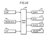
- the embodiment under discussion includes a simplified control arrangement which will be described with reference to Figs. 26 and 27.
- the control arrangement comprises a control circuit 400 having as inputs a start button 402, a stop button 404 and the pressure switch 290.
- the control circuit 400 has four outputs connected respectively to the solenoid 268, the motor 230, an indication lamp 406 mounted on the exterior of the apparatus and a low pressure indicator 408 also mounted on the exterior of the apparatus.
- the motor 230 is momentarily energized to cause the rotor 224 to rotate so that the vane portion 228a engages the peg 248 to open the valve 232 and permit water to enter the carbonation chamber 200.
- the apparatus is constructed so that water flows into the carbonation chamber at a rate which is such that it reaches the required level W by the end of a five second period, this period being timed by the control circuit 400.
- the control circuit 400 supplies a signal which causes the solenoid 268 to be turned on to supply carbon dioxide to the carbonation chamber via the valve 258.
- the carbonation chamber After a short period, the carbonation chamber reaches the required pressure and in response to this a signal is supplied by the pressure switch 290 to the control circuit 400 which turns the motor 230 on to begin the carbonation operation. If the required pressure is not reached within a predetermined time, the control circuit activates the low pressure indicator 408. The carbonation operation can continue for a maximum period of five seconds which period is timed by the control circuit 400 and begins with the signal from the pressure switch 290. The apparatus is arranged so that the maximum desired degree of carbonation is achieved by the end of the five second period. If, however, the user desires a lower level of carbonation, he can terminate the carbonation operation at any time by pressing the stop button.
- the control circuit 400 causes the indication lamp 406 to flash at intervals during the five second period in which carbonation is taking place. Thus, by counting the number of flashes, the user will have an idea of the level of carbonation achieved.
- Fig. 27 illustrates an operation in which carbonation was determined after two flashes of the indication lamp. After the end of the five second carbonation period, the circuit 400 turns the indication lamp on for a period to indicate that carbonation is complete.
- the circuit 400 de-energizes the solenoid 268 and motor 230.
- the concentrate containers are then pressurized as previously described and the operator may rotate the lever 310 to the position required to select the concentrate which he wishes to use and then depresses the lever to discharge the carbonated water and the selected concentrate.
- a further recess 318 may be provided in the arcuate wall 320 to permit the operator to discharge carbonated water without any concentrate.
Abstract
Description
- This invention relates to fluid treatment. More particularly, the invention concerns apparatus and method for carbonating water and/or for dispensing flavoured drinks, especially carbonated drinks.
- Known methods of carbonating water fall into two groups. In one group, the carbon dioxide gas is injected into the water to be carbonated at a low level so that it forms bubbles which float up through the water to the surface so that carbon dioxide in the bubbles becomes absorbed in the water. This method has been widely used. For example, it is common practice to utilize this method in relatively small carbonating apparatus for home use and operable for dispensing carbonated water in quantities sufficient to form one drink. Examples of apparatus utilzing the injection method of carbonation can be seen in UK patent specification No.412,849 (Schwendimann) and US patent No.2,826,401 (Peters). Both Schwendimann and Peters provide injectors which are rotatable and which have laterally directed members at their bottom end to assist in the mixing of the carbon dioxide gas with the water. The main problem with the injection method of carbonation is that it is only effective if relatively high pressures are used so that, during carbonation, the carbonation chamber is pressurized to a relatively high level. Typically, for example, pressures of 170 psig (11.6 bars) may be involved.
- The second group of known methods for achieving carbonation involves spraying or atomizing the water in an atmosphere of carbon dioxide gas. In these methods, a carbonation chamber may be prefilled with carbon dioxide gas and the water introduced into the chamber by spraying. Alternatively, or in addition, when the carbonation chamber has been partly filled with water, the water may be drawn upwardly and sprayed into the carbon dioxide atmosphere above the water level in the chamber. In this method, carbon dioxide is dissolved into the water droplets in the spray and the droplets carry the carbon dioxide in dissolved form into the body of the water to effect carbonation. Typical proposals for achieving carbonation by this method are disclosed in US patent No.2,306,714 (Rowell) and US patent No.2,391,003 (Bowman). A major problem with these methods also is that they require the carbonation chamber to be pressurized to a relatively high level similar to that mentioned above. Also these methods are slow, so that a long time is required to achieve an adequate degree of carbonation.
- One of the objects of the present invention, therefore, is to provide an improved method and apparatus for carbonation.
- According to one aspect of the present invention, a carbonation method is provided in which a carbonation chamber is partly filled with water and an atmosphere comprising carbon dioxide is provided above the level of water in the chamber, the method comprising continuously or repeatedly drawing or forcing gas from said atmosphere down into the water.
- In another aspect, the invention provides carbonation apparatus comprising a carbonation chamber adapted to be partially filled with water and to contain an atmosphere comprising carbon dioxide above the level of water in the chamber, and means for continuously or repeatedly drawing or forcing gas from said atmosphere down into said water.
- In a further aspect, the invention provides carbonation apparatus comprising a carbonation chamber adapted to be partially filled with water and to contain an atmosphere including carbon dioxide in the space above said water, and a movable member, preferable a rotatable member, which in operation moves repeatedly between said atmosphere and said water so as to cause gas from said atmosphere to be moved downwardly into said water.
- According to a further aspect, the present invention provides carbonation apparatus comprising a carbonation chamber adapted to be partially filled with water and to contain an atmosphere including carbon dioxide gas in a space above the water, and a member which is rotatable about a non-vertical axis and has a plurality of vanes. Preferably, the axis of rotation is horizontal.
- It has been found that carbonation may be achieved in accordance with the preferred aspects of the invention as defined above without the need for high pressures. Typically, pressures of around 100 psig (6.8 bars) are adequate but lower pressures, for example down to 60 psig (4.1 bars) may be used. The invention is particularly applicable to apparatus for use in the home in which the capacity of the chamber is such that the quantity of water carbonated in each carbonation operation is sufficient for one drink.
- Applicants acknowledge US patent No.3,044,878 (Knedlik) which discloses an apparatus for producing semi-frozen beverages. The apparatus illustrated in the drawings of the patent comprises a cylindrical chamber arranged with its axis horizontal. Water which has been pre-mixed with flavouring concentrate and carbon dioxide is introduced into the chamber so as to substantially fill it and the liquid in the chamber is maintained at a temperature which is below its freezing point. To prevent formation of ice particles, a vaned rotor is provided in the chamber with its axis horizontal. The rotor extends from end to end of the chamber and the vanes extend to positions close to the internal cylindrical walls of the chamber so as to stop the formation of ice particles on those walls. The rotor is driven to provide vigorous and continuous agitation. Since the liquid substantially fills the chamber and since the rotor extends substantially from end to end and to positions close to the peripheral wall of the chamber, the liquid in the chamber will be swept around, and in contact with, the cylindrical internal wall of the chamber. Accordingly, there will be no discernable CO₂ atmosphere above the water in the chamber and the vanes of the rotor will not function to force CO₂ from an atmosphere thereof down into the water as in a preferred form of the present invention. Further, in Knedlik the rotor is driven continuously both when the apparatus is in the "idling" state and when beverage is being discharged, at which time the liquid in the chamber is simultaneously replenished to keep the chamber full. In the preferred form of the present invention, the carbonation process is stopped prior to discharge of the carbonated liquid, the chamber being emptied at this point, because agitation of the liquid as it is leaving the chamber would tend to cause de-carbonation. The Knedlik apparatus is intended for commercial use in which continuously available beverage is provided and is not suitable for home use in view of its complexity and high cost. Applicants also acknowledge that Knedlik states that CO₂ and water might be introduced via separate conduits into his chamber but even with this modification the function of the rotor in Knedlik will not be changed and there will be no discernable CO₂ atmosphere above the water level.
- Normally, carbonated drinks are mixed with a flavoured concentrate (syrup). Desirably, therefore carbonation apparatus, in addition to being provided with means for carbonating water, should also be provided with means for dispensing a selected concentrate and mixing that concentrate with the carbonated water. A known method of dispensing the concentrate involves supplying the vessel containing the concentrate with carbon dioxide under pressure from the carbon dioxide supply tank so that a required quantity of concentrate is forced out of the container to a dispensing nozzle from which it may be discharged into a glass for mixing with the carbonated water. The above mentioned US patent No.2,391,003 (Bowman) illustrates this method. The disadvantage of the method is that carbon dioxide is wasted.
- In another aspect, the invention is concerned with an improved method of dispensing concentrate.
- According to a further preferred aspect of the present invention, carbonation apparatus comprises a carbonation chamber for receiving water and carbon dioxide gas and concentrate dispensing means which utilizes gas from the carbonation chamber, after a carbonation operation, for causing a movement of said concentrate to enable said concentrate to be dispensed. Preferably, said concentrate is moved directly from a concentrate container to a discharge nozzle under said pressure of gas from said carbonation chamber.
- In another preferred aspect, the invention provides a carbonation method and apparatus in which, to achieve carbonation, a carbonation chamber is pressurized and in which the pressure in said carbonation chamber is utilized to cause movement of concentrate towards a dispensing nozzle. In a preferred form, the upper part of the carbonation chamber is connected to an upper part of a concentrate container through a valve so that, upon opening of the valve, the concentrate container becomes pressurized.
- In this way, concentrate may be dispensed without wasting fresh carbon dioxide i.e. carbon dioxide direct from the carbon dioxide tank.
- Applicants acknowledge US patent No.3,809,292 (Booth) which discloses a commercial carbonation apparatus in which a supply of carbonated beverage is continuously available. Water is carbonated in a carbonation chamber by the injection method as previously described. The water partly fills the chamber and the chamber is maintained at a high pressure. Pressure from the chamber is supplied to concentrate containers for pressurizing them for discharging the concentrate. However, in this disclosure, the carbonation chamber is not depressurized at the end of a carbonation operation and thus this patent fails to disclose the concept of using otherwise waste CO₂ for pressurizing the concentrate containers.
- Preferably, carbonation apparatus should include a number of concentrate containers for containing respectively concentrates of different flavours. In prior proposed apparatus the containers are connected to outlet orifices for the discharge of the concentrate via electro-magnetically operated valves. Selection is made by actuating the appropriate valve. Such arrangements are relatively expensive.
- According to a further preferred aspect of the present invention, a concentrate selector arrangement comprises a number of valves, a manually movable member for effecting selection, and mechanical means for actuating the valve according to the position of the selector member.
- In a preferred form, the selector member or a part thereof, is utilized to transmit movement from an actuating member to the selected valve. The actuating member may be so arranged that when a glass is positioned to receive carbonated water and concentrate, the actuator member is operated to cause dispensing.
- In a preferred form, a carbonated drink dispensing device comprises an actuating member which upon movement opens both a first valve for the discharge of carbonated water and a selected one of a plurality of further valves for the discharge of a selected concentrate, a movable selector member being provided for selecting the further valve to be opened. In a preferred form, the selector member is attached to a part of the first valve so that the first valve and the selected further valve are opened at approximately the same time.
- Concentrates of different flavour generally have different viscosities and accordingly there is need to control the quantity of concentrate dispensed. The present invention provides, in a further preferred aspect, a carbonation apparatus capable of dispensing selectively different ones of a plurality of concentrates, the means for dispensing the concentrates including different conduits for transporting the concentrates from respective concentrate containers to a discharge point, at least one of said conduits having a bore of different cross-sectional area to the other or at least one of the others to compensate for differences in viscosity between the concentrates. With this arrangement, it is possible to utilize the same pressure for discharging each of the concentrates whilst metering the amount of concentrate dispensed.
- The invention is described further by way of the accompanying drawings in which:
- Fig. 1 is a diagram showing apparatus according to a preferred embodiment of the present invention;
- Fig. 2 is a view in the direction of the arrow A of Fig. 1 showing a part of the apparatus;
- Fig. 3 is a diagram showing how carbonation is achieved in the apparatus of Figs. 1 and 2;
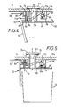
- Fig. 4 is a sectional view showing part of a valve unit included in the apparatus of Fig. 1, and shows the valve unit in its closed position;
- Fig. 5 is a view similar to Fig. 4 but showing the valve unit in its open position;
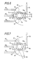
- Fig. 6 is a plan view showing part of the valve unit of Figs. 4 and 5;
- Fig. 7 is a plan view similar to Fig. 6, but showing a concentrate selector element in a different position;
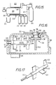
- Fig. 8 is a block diagram illustrating a controller unit included in the apparatus of Fig.1;
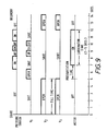
- Fig. 9 is a timing chart showing the timing of various operations performed under control of the controller unit of Fig. 8;
- Fig. 10 is a flow chart illustrating in outline a programme followed by the controller unit of Fig. 8;
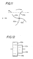
- Fig. 11 is a view similar to Fig. 2 showing a modification to the apparatus of Fig.1;
- Fig. 12 is a view on the arrow B of Fig. 11;
- Fig. 13 shows a further modification to the apparatus of Fig. 1;
- Fig. 14 illustrates yet a further modification;
- Fig. 15 is a diagram of a carbonation apparatus according to a further embodiment of the present invention;
- Fig. 16 is a diagrammatic section through a carbonation chamber included in the apparatus of Fig. 15;
- Fig. 17 is a perspective view of a rotor included in the apparatus of Figs. 15 and 16;
- Figs. 18 to 21 show a water inlet valve for the carbonation chamber of Fig. 16, in four positions;
- Fig. 22 shows a section through a carbon dioxide control valve arrangement mounted on a carbon dioxide supply bottle;
- Fig. 23 is a diagrammatic plan view of a valve arrangement for selecting concentrate and for discharging carbonated water from the carbonation chamber;
- Figs. 24 and 25 are sections on the line A-A of Fig. 23 and show the valve arrangement in closed and opened positions respectively;
- Fig. 26 is a block diagram of the circuitry included in the apparatus of Fig. 15; and
- Fig. 27 is a timing diagram illustrating operation of the apparatus of Figs. 15 to 26.
- With reference to Fig. 1, the carbonation apparatus comprises a
carbonation chamber 10, awater supply tank 12, a carbondioxide supply tank 14 and concentratesupply arrangement 16. Avalve unit 18 is disposed on the bottom of thechamber 10 for dispensing both carbonated water from thechamber 10 and a selected concentrate from thearrangement 16 into aglass 20. - Water is supplied from the
tank 12 to thechamber 10 through a valve V₂ controlled by a solenoid S₂, aconduit 22 and aball valve 24 located inside thechamber 10. Avent 26 connected to the interior of thechamber 10 by means of apipe 28 permits air in thechamber 10 to be vented to atmosphere while thechamber 10 is being filled with water. Thepipe 28 projects down into thechamber 10 a distance which is such that its lower end is imersed in the water when thechamber 10 has been filled with water to the required level indicated by W. - Carbon dioxide is supplied from
container 14 through valve V₁, controlled by a solenoid S₁, and aconduit 30 leading into thechamber 10 at the top. - A
ball 29 located in thevent 26 is arranged to close the vent if water is forced up thepipe 28 due to pressurization of the chamber. For this purpose, the ball is movable upwardly into sealing engagement with avalve seat 31 at the top of the vent. Theball 29 is also arranged so that it closes the vent, in response to increasing gas pressure in thechamber 10, if carbon dioxide is introduced into thechamber 10 with the water level below the lower end of thepipe 28 so that carbonation may be achieved in these circumstances. - A
paddle 32 is mounted inside thechamber 10 for rotation about a horizontal axis, being carried on theshaft 34 of amotor 36 which is mounted on the outside of thechamber 10. Theshaft 34 may project through an opening (not shown) in the wall of thechamber 10 with an appropriate seal being provided. Alternatively, theshaft 34 could be connected to themotor 36 by a magnetic coupling. - The
paddle 32 comprises three pairs ofvanes shaft 34. Thevanes shaft 34 to one side of thevanes vanes shaft 34 at the other side of thevanes shaft 34. The anglar position of theshaft 34 shown in Figs. 1 and 2 is such that thevanes vane 38a projects above the water level W almost to the top of thechamber 10 whereas thevane 38b projects almost to the bottom of thechamber 10 in this position. In Fig. 2, L indicates the length of the portion of each vane which projects above the water level W when the vane is in its uppermost position with the paddle stationary and the apparatus horizontal and D indicates the diameter of the circle swept by the tip of each vane as the paddle rotates. L should be at least 5% of D and preferably greater than 12% of D. It is particularly preferred that L should be from 12% to 15% of D for achieving optimum carbonation. As thepaddle 32 rotates, the vanes move from within the water, into the space above the water level, and back into the water. - In operation, the
chamber 10 is partially filled with water up to the level W. Thereafter, carbon dioxide is admitted to the space above the level of water in thechamber 10 by opening the valve V₁. Apressure switch 44 senses the gas pressure in thechamber 10. When this reaches the required level preferably in therange 60 to 140 psig (9.6 bars), for example 100 psig (6.8 bar), the solenoid is actuated to close the valve V₁. Theball valve 24 prevents water being forced back up theconduit 22 due to the pressure in thechamber 10. After the pressure has reached the required value, themotor 36 is energized to cause thepaddle 32 to rotate. Typically, this rotation may be at a speed from 500 to 2000 rpm, preferably within the range 1000 to 1500 rpm. This rotation is continued for several seconds, for example 5 seconds, during which carbonation of the water takes place. The degree of carbonation may be varied by varying the time for which the paddle is driven and/or by varying the pressure of the atmosphere containing carbon dioxide in the space in thechamber 10 above the water level. - The action of the paddle is to force the gas in the space above the water level down into the water. As much gas as possible should be forced into the water and it should be carried to a level which is as deep as possible. To achieve these purposes, the vanes are dimensioned, as discussed above, such that they reach nearly to the top and nearly to the bottom of the
chamber 10. Also, therefore, the paddle acts to shift water from the bottom portion of thechamber 10 to a higher level so that water at all levels may be uniformly carbonated. Further, the paddle creates intense agitation of the water causing it to be splashed up into the atmosphere of carbon dioxide thereby to assist with carbonation and thereby also achieving uniform carbonation. As can be seen in Fig. 3, each vane, in addition to forcing carbon dioxide in gaseous form in front of it into the water, creates a vortex behind it which draws carbon dioxide in gaseous form in and causes the gas to be carried down into the water. Fig. 3 shows the fluid flow lines created by the vane as it moves. It can be seen from Fig. 1, that thepaddle 32 is located to one side of thechamber 10, which is preferably of circular cross-section as seen in plan view. With this arrangement, the water in thechamber 10 is also caused to rotate around thechamber 10 so that, as the paddle is driven, different portions of the body of water in thechamber 10 move past the paddle to be subjected to the carbonation action. - As carbonation progresses, gas from the space above the water level in the
chamber 10 is absorbed by the water so that the gas pressure reduces. This is sensed by thepressure switch 44 and, when the pressure drops below a certain level, say a drop of 5 psig (0.3 bars), the valve V₁ is again opened to admit more carbon dioxide to thechamber 10. - The
concentrate dispensing arrangement 16 comprises threecontainers Dip tubes respective containers respective conduits valve unit 18 for supplying concentrate from the containers to the valve unit. The upper part of each of thecontainers conduit arrangement 64 to the upper part of thechamber 10. A valve V₃ is located in theconduit arrangement 64 and is controlled by the solenoid S₂. After completion of the carbonation operation in thechamber 10, the valve V₃ is opened to permit the upper parts of thecontainers chamber 10. Apressure relief valve 66 connected to theconduit arrangement 64 limits the pressurization of thecontainers containers dip tubes conduits - The
valve unit 18, the details of which are illustrated in Figs. 4 to 7, provides three functions. First, it relieves the pressure in thecarbonation chamber 10. Second, it permits selection of which of the concentrates from thecontainers chamber 10. - For relieving the pressure in the
carbonation chamber 10, thevalve unit 18 comprises anexhaust valve 68 which is connected to the upper part of thechamber 10 by aconduit 70 and part of theconduit 30. Theexhaust valve 68 includes a verticallymovable valve member 68a which is spring urged to its upper, closed position. Anactuating lever 72 has oneend 72a pivotally connected to thevalve member 68a for pushing thevalve member 68a downwards to open thevalve 68 thereby permitting gas in the upper part of thechamber 10 to be exhausted to atmosphere through theconduits valve 68. - The actuating
lever 72 comprises anupper arm 72b and a downwardly directedarm 72c. Thelever 72 is attached by apivot 72d, intermediate the ends of theupper arm 72b, to allow hollowcylindrical sleeve 74 which is mounted for vertical sliding movement in an aperture in thebase 10a of thechamber 10. Thesleeve 74 forms a valve for permitting discharge of carbonated water from thechamber 10 and for this purpose has got lateral openings 74a near its upper end and ahead 74b which carries aseal 76 which engages the inside surface of thebottom wall 10a of thechamber 10 when thesleeve 74 is in its lower position so that at this time water cannot escape from thechamber 10. - At completion of carbonation, the
chamber 10 is pressurized so that thevalve head 76 is pressed firmly against the inside surface of thebottom wall 10a of thechamber 10. Consequently, if the downwardly directedarm 72c of thelever 72 is moved to the left as shown by the arrow X in Fig. 4, thelever 72 rotates about thepivot 72d, thesleeve 74 remaining stationary, so that thevalve 68 is opened, thus relieving the pressure in thechamber 10. Continued movement of thearm 72c in the direction of arrow X in Fig. 4 will cause the lever to pivot about itsend 72a, so that thesleeve 74 slides upwardly to the position shown in Fig. 5, in which position thesleeve valve 74 is opened to permit carbonated water to be discharged from thechamber 10. The actuatingmember 72 is designed so that itslower arm 72c is arranged to be engaged by theglass 20 when placed in position so that as theglass 20 is moved to the left relative to the valve unit as seen in Figs. 4 and 5, first of all thevalve 68 is opened, thesleeve 74 being held stationary by the pressure in thechamber 10, and thereafter, when the pressure in thechamber 10 has been relieved, thesleeve 74 moves upwardly to discharge carbonated water through the opening 74a and thesleeve 74 into theglass 20. - The
valve unit 18 includes threeconcentrate dispensing valves conduits valves valve 80 comprises a vertically movable valve member 84 urged downwardly by aspring 86 to the closed position (Fig. 4). Aconcentrate selector bar 88 is secured to the lower end of thesleeve 74 which is rotatable about its axis (which is vertical). One end of thesleeve 88 carries a nob orfinger grip 90 for effecting this rotation so as to position theopposite end 92 beneath a selected one of thevalves end 92 of thebar 88 beneath thevalve 80 and Fig. 7 shows it beneath thevalve 82. Thus, when thesleeve 74 is raised by actuation of thelever 72 so as to discharge carbonated water into theglass 20, the selected one of thevalves end 92 of thebar 88 so as to open the valve by virtue of its valve member 84 being raised. The construction of the valve member 84 is similar to that ofsleeve 74 i.e. it is hollow and is provided with lateral apertures so that the selected concentrate is discharged through the selected valve member 84 and through anaperture 94 in thebar 82 and into theglass 20. As indicated above, this discharge of concentrate takes place due to the pressure introduced into the upper parts of the concentrate containers. - To avoid possible contamination of one concentrate with another,
separate apertures 94 may be provided in thebar 88 for the different valves, this of course requiring appropriate positioning of the apertures and thevalves aperture 94 could be sufficiently large to ensure that concentrate flows through theaperture 94 without contacting the edges thereof thus avoiding contamination: of course in this case means must be provided to ensure that thebar 88 engages the valve member 84 for the purpose of opening the associated valve. As a further alternative, the valve members 84 could have a nozzle portion which project down through theapertures 90 to ensure that theaperture 94 does not become contaminated. - With reference to Fig. 8, a microprocessor controlled
controller unit 100 receives power from apower supply 102 and has three inputs connected respectively to receive signals from aSTART button 104, thepressure switch 44 and a carbonation time selector 106. Theunit 100 has outputs to the solenoids S₁ and S₂, to themotor 36 and to threeindicators START button 104, theWAIT indicator 110 is switched on and the solenoid S₂ is energized to open the valve V₂ and permit water to flow from thetank 12 into thecarbonation chamber 10. At the same time the valve V₃ opens but this is of no functional significance at this time. Theunit 100 is arranged to maintain the valve V₂ open for a period of 5 seconds, the apparatus being designed so that during this time period the rate of flow of water into thechamber 10 is sufficient that at the end of the 5 second period the water is at the required level W. Thecontroller 100 then de-energizes the solenoid S so as to close the valve V₂ (and also the valve V₃). Thecontroller 100 then energizes the solenoid S₁ to open the valve V₁ and permit carbon dioxide gas to flow into the space above the water inchamber 10. The pressure in this space is continuously monitored bypressure switch 44 and thecontroller 100 de-energizes solenoid S₁ to close valve V₁ when the pressure reaches the required level, say 100 psig (6.8 bars). Alternatively, if the pressure has not reached this level within two seconds, thecontroller 100 de-energizes the solenoid S₁ to close the valve V₁ and at the same time energizes the LOW GAS indicator 108. Thecontroller 100 then energizes themotor 36 so as to cause the water in thechamber 10 to be carbonated. The time for which themotor 36 is energized is determined by the setting of thecarbonation selector 10 according to the degree of carbonation required by the user. As shown in Fig. 9, the carbonation time may vary from 2 to 5 seconds. As also shown in Fig. 9 and in Fig. 10, during the carbonation operation, thepressure switch 44 will from time to time indicate that the pressure in the upper part ofchamber 10 has reduced, say by 5 psig (0.3 bars), due to absorption of carbon dioxide in the water. When this occurs, the valve V₁ is reopened until the pressure again reaches the required level, say 100 psi. This opening and closing of the valve V₁ in response to thepressure switch 44 going off and on may occur several times during the carbonation time. - At the completion of the selected carbonation time, solenoid S₂ is again energized, this time to open the valve V₃ (although the valve V₂ also opens but without any effect) so that the
concentrate containers chamber 10. The valve V₃ is held open for 2 seconds and is then closed. Thereafter, the controller energizes theREADY indicator 112 so that the user may now dispense a drink via thevalve unit 18 as previously described. - As will be understood, the quantity of water contained in the
chamber 10 is preferably that appropriate for a single drink. By way of example, therefore, the total capacity of thechamber 10 may be 9½ fluid ounces (1.27 litres) and the apparatus may be arranged so that 5/6 of this capacity is filled with water (i.e to the level W) and 1/6 of the capacity is left for containing gas. In this way, about 8 fluid ounces of carbonated water will be made and dispensed each time the machine is operated. It is possible to vary from these figures. - Figs. 11 and 12 show a modified form of paddle. In this modification, two pairs of
vanes vanes vanes - In the modification of Fig. 13, a
belt 124 which is mounted onwheels 126 carriescups 128 so that when the belt is driven by driving one of thewheels 126, thecups 128 collect gas when above the level W and carry that gas down into the water for achieving carbonation. - In the modification of Fig. 14, a reciprocating
inverted cup member 130 is provided. This is movable from the full line position above the water level W to the broken line position near to the bottom of thechamber 10 so as to carry gas down into the water for carbonation purposes, when themember 130 is reciprocated vertically. - Various other modifications are possible within the scope of the invention. For example, the carbonation method described may be utilized in a variety of different forms of the apparatus independently of the concentrate dispensing arrangement and the
particular valve unit 18 which have been illustrated. Also, the concentrate dispensing arrangement illustrated may be used with other forms of carbonation apparatus and other forms of selector valve means. The selector valve means illustrated may also be used with other forms of carbonation apparatus and other arrangements for supplying concentrate. - As examples of further modifications, it is possible to vary the timing of the operations. For example, it is possible to arrange that the
motor 36 be energized before the pressure in thechamber 10 has reached the level set by thepressure switch 44. With this modification, carbonation may begin as soon as the admission of carbon dioxide to thechamber 10 starts. - As a further modification, means other than that illustrated in Figs. 4 and 5 may be provided for relieving the pressure in the
chamber 10 before discharging carbonated water; or the apparatus may be constructed so that discharge of the carbonated water takes place under pressure. - Further, adjustable means, such as valves, may be provided in
conduits - The carbonation apparatus shown in Fig. 16 comprises a
carbonation chamber 200 which is connected to awater reservoir 202 at 204. Acarbon dioxide bottle 206 is connected to thechamber 200 through avalve arrangement 208 and agas supply pipe 210. Avalve 212 is mounted at the bottom of thechamber 200 for discharging carbonated water and a selected concentrate from any one of theconcentrate bottles valve 212 viaconcentrate supply lines 220. Theconcentrate bottles chamber 200, following a carbonation operation. For this purpose, thebottles chamber 200 through agas line 222, thevalve arrangement 208 and thegas line 210. - The
carbonation chamber 200 contains arotor 224, which comprises acylindrical body 226 and sixradial vanes 228. Therotor 224 is mounted for rotation about a horizontal axis and functions in the same way as therotor 32 described with reference to Figs. 1 and 3 to drive carbon dioxide in gaseous form from a carbon dioxide atmosphere above the water level down into the water to carbonate the water.Rotor 224 is supported in adrive shaft 225 which is driven by amotor 230 mounted outside thechamber 200. Thechamber 200 also contains avalve 232 for controlling the flow of water from thereservoir 202 into thechamber 200. In Fig. 16, thevalve 232 is shown in the fully closed position which it assumes when thechamber 200 has been filled with water to the level W and has been pressurised, in preparation for a carbonation operation, with gas from thesupply bottle 206. Aseal 233 prevents water leaking along theshaft 225. L and D shown in Fig. 16 indicate the same features as in Fig. 2 and should have the same relationship. - The
valve 232 comprises acylindrical sleeve 234 which fits closely within but is movable relative to acylindrical boss 236, a disk shapedbody 238 and a downwardly projectingstem 240 which may engage the bottom of thechamber 200 to limit downward movement of the valve. Apeg 242 integral with the inside of theboss 236 engages in aslot 244 in thesleeve 234. The shape of theslot 244 can be seen in Figs. 18 to 21. - Figs. 18 to 21 show the positions which the
valve 232 assumes during operation of the apparatus. In Fig. 18, the valve is shown in the same position as in Fig. 16 and in this Figure it can be seen that the valve is in its uppermost position which is such that an O-ring 246 is compressed between thebody 238 of the valve and the lower end surface of theboss 236 to form a gas tight seal. In this position, thepeg 242 is located in the lowermost portion of theslot 244. As already stated, thevalve 232 assumes the position shown in Figs. 16 and 18 when thechamber 200 is pressurised with carbon dioxide. After completion of a carbonation operation, when thechamber 200 is depressurised, the weight of water on thevalve 232 causes it to move downwardly from the position shown in Fig. 18 to that shown in Fig. 19 in which ahorizontal abutment 248 provided in the wall of theslot 244 rests on thepeg 242 and thus prevents further downward movement of thevalve 232. In the position shown in Fig. 19, the valve is still closed so that water is prevented from entering thechamber 200 from the reservoir 202 (although it should be understood that a small amount of leakage may arise). The valve may be opened by rotating it about a vertical axis from the position shown in Fig. 19 to that shown in Fig. 20 in which theabutment surface 248 is clear of thepeg 242. This rotation is achieved by causing therotor 224 to be momentarily rotated so that aportion 228a of one of thevanes 228 engages afurther peg 248 projecting from the side of the disk shapedbody 238. This engagement is shown in Fig. 20. After thevalve 232 has been rotated to the position shown in Fig. 20, it may fall further under the weight of water until thestem 240 engages the bottom of thechamber 200 as shown in Fig. 21. In this position, theslot 244 andfurther slots 250 in thesleeve 234 are located below theboss 236 so that water may flow into thechamber 200 through these slots. - As the water approaches the level W, the
valve 232 is caused to float upwardly until it returns to the position shown in Fig. 20 at which time the water supply is again cut off. Thereafter, carbon dioxide under pressure is introduced into thechamber 200 and thevalve 232 is forced back to the position shown in Fig. 18. During its movement from the position shown in Fig. 20 to that shown in Fig. 18, aninclined surface 252 in theslot 244 engages thepeg 242, thereby causing thevalve 232 to rotate so that thepeg 242 is again located in the lowest part of theslot 244 which, as shown in Fig. 18, is below theabutment surface 248. - The
valve arrangement 208 is novel and is shown in more detail in Fig. 22. It comprises abody 252 having acap arrangement 254 which is secured by conventional means (not shown) such as screw threads to thecarbon dioxide bottle 206. A conventional means (not shown) is provided to enable thevalve arrangement 208 to be connected to thebottle 206 to put the interior of thebottle 206 into communication with thevalve arrangement 208 without significant loss of carbon dioxide gas when the connection is made. - The
body 252 contains apassage 256 which communicates via avalve 258 with the interior of thebottle 206. Thegas supply pipe 210 is connected to thepassage 256 so that when thevalve 258 is opened carbon dioxide gas from thebottle 206 may be supplied to thecarbonation chamber 200. Thepassage 256 is also connected via apassage 260 and apipe 262 to apressure sensing chamber 264 one wall of which is constituted by adiaphragm 266. Asolenoid 268 has itscoil 274 secured to arod 270 of which the lower end engages the upper surface of thediaphragm 266 and which is biassed downwardly by acompression spring 272. The armature (not shown) of thesolenoid 268 is connected by arod 276 to oneend 278 of alever 280. The opposite end of thelever 280 is connected by apivot 282 to astem 284 of avalve 286 which is located in thebody 260 to place thegas pipes valve 258 has astem 288 which abuts thelever 280 at a position intermediate it ends. A pressure sensitive switch, constituted byelectrical contacts 290 diagrammatically shown in Fig. 22, is provided so as to give an electrical signal in response to the pressure in thechambers 264 reaching a value which is sufficiently high to raise thediaphragm 266. - The
valve arrangement 208 is such that when thesolenoid 268 is energized, therod 276 is drawn downwardly to cause thelever 280 to pivot about thepivot 282 thereby opening thevalve 258 to permit carbon dioxide gas to be supplied to the carbonation chamber. The strength of thespring 272 is such as to ensure that when the solenoid is energized therod 276 is drawn downwardly rather than therod 270 being drawn upwardly against the force of thespring 272. The pressure in thecarbonation chamber 200 is sensed by thediaphragm 266 and when this pressure has reached a level sufficient for the carbonation operation to begin, for example 100 psig (6.8 bars), thediaphragm 266 is raised. Also the pressuresensitive switch 290 opens to give a signal indicating that the required pressure level has been reached. The upward movement of thediaphragm 266 raises the whole of thesolenoid 268 so that thelever 280 is pivoted upwardly about thepivot 282 and thevalve 258 closes under the action of the gas pressure in thebottle 206 and the force of thestem 288 against thelever 280 holds thevalve 286 in its closed position. The carbonation operation may now begin and, as carbon dioxide is absorbed into the water in thecarbonation chamber 200, the pressure in thechamber 200 will decrease to some extent, permitting thediaphragm 266 to move downwardly so that thevalve 258 is again opened. A balanced condition will be reached at which thevalve 258 is just sufficiently open to maintain the required pressure in thecarbonation chamber 200 during the carbonation operation. - After carbonation has been completed, the
solenoid 268 is de-energized. Thereafter, the pressure in thecarbonation chamber 200, thegas supply pipe 210 and thepassage 256 is sufficient to open thevalve 286 so as to pressurize theconcentrate supply containers containers Valve 286 acts as a non-return valve ensuring pressure in thecontainers chamber 200 is emptied. - The
valve arrangement 208 is particularly simple and economic to construct and therefore advantageous, particularly as only single solenoid is needed. - As with the previously described embodiments, carbonation is achieved in the embodiment under description by causing the
rotor 224 to be driven so that the vanes orblades 228 move continuously and repeatedly between the water in thechamber 200 and the carbon dioxide atmosphere which is formed above the water so as to drive carbon dioxide from the atmosphere down into the water. Actuation of themotor 230 to start the carbonation operation is achieved in response to the signals from the pressuresensitive switch 290. - Discharge of carbonated water from the
carbonation chamber 200 and selection of the desired concentration from thecontainers valve 212 which is shown in more detail in Figs. 23 to 25. - The
valve 212 comprises ahousing 300 which is secured to the underside of thecarbonation chamber 200 and includes asleeve 302 in which acylindrical valve member 304 is mounted for vertical sliding movement. Avalve head 306 is secured to the top of thecylindrical valve member 304 and engages the inside surface of the bottom of thechamber 200 when in the closed position to prevent discharge of water from thechamber 200, this position being shown in Fig. 24. As shown in Fig. 25, thevalve member 304 may be raised to its open position in which water may be discharged from thechamber 200 by passing throughapertures 308 and then downwardly through the interior of thecylindrical valve member 304, exiting via the open bottom end ofmember 304. - An
actuating lever 310 is pivotable as shown in Fig. 25 for raising thevalve member 304 to the open position. Thelever 310 is located in position by aspindle 312 projecting downwardly from thevalve head 306 through anaperture 314 in thelever 310. Theaperture 314 is sufficiently large relative to thespindle 312 to permit the pivoting movement of thelever 310. An innerarcuate wall 316 provided in thehousing 300 acts as fulcrum for the pivoting movement of thelever 310, this pivoting movement being achieved by the operator pressing down on theouter end portion 310a of thelever 310. Thelever 310 is rotatable in a horizontal plane about thespindle 312 and can be pivoted to the position shown in Fig. 25 at any one of three positions defined byrecesses 318 provided in an outerarcuate wall 320 of thehousing 300, the outerarcuate wall 320 preventing the pivotal movement of the lever shown in Fig. 25 unless it is in register with one of therecesses 318. Stability is provided to thelever 310 by upwardly and downwardly directedarcuate projections sleeve 302 and the inner surface of thearcuate wall 316. - When the
lever 310 is in one of the positions defined by therecesses 318, its inner end 310b engages a respective one of threeconcentrate selector valves 322 so that when thelever 310 is pivoted as shown in Fig. 25, the correspondingselector valve 322 is opened against acorresponding spring 324 to permit the corresponding concentrate to flow into the interior of thehousing 300 via thecorresponding conduit 220 and acorresponding boss 236 associated with thevalve 322 for mixing with the carbonated water, the concentrate and the carbonated water falling from thevalve arrangement 212 into an appropriate vessel such as a glass 215 (Fig. 15). The concentrate selector and valve arrangement illustrated in Figs. 22 to 25 is particularly simple and inexpensive to manufacture and has the advantage that the carbonated water tends to wash thevalves 322 and their surroundings so that an undesirable build up of stale concentrate may be avoided. - The embodiment under discussion includes a simplified control arrangement which will be described with reference to Figs. 26 and 27. The control arrangement comprises a
control circuit 400 having as inputs astart button 402, astop button 404 and thepressure switch 290. Thecontrol circuit 400 has four outputs connected respectively to thesolenoid 268, themotor 230, anindication lamp 406 mounted on the exterior of the apparatus and alow pressure indicator 408 also mounted on the exterior of the apparatus. - As can be seen from Fig. 25, when the
start button 402 is pressed, themotor 230 is momentarily energized to cause therotor 224 to rotate so that thevane portion 228a engages thepeg 248 to open thevalve 232 and permit water to enter thecarbonation chamber 200. The apparatus is constructed so that water flows into the carbonation chamber at a rate which is such that it reaches the required level W by the end of a five second period, this period being timed by thecontrol circuit 400. At the end of this period, thecontrol circuit 400 supplies a signal which causes thesolenoid 268 to be turned on to supply carbon dioxide to the carbonation chamber via thevalve 258. After a short period, the carbonation chamber reaches the required pressure and in response to this a signal is supplied by thepressure switch 290 to thecontrol circuit 400 which turns themotor 230 on to begin the carbonation operation. If the required pressure is not reached within a predetermined time, the control circuit activates thelow pressure indicator 408. The carbonation operation can continue for a maximum period of five seconds which period is timed by thecontrol circuit 400 and begins with the signal from thepressure switch 290. The apparatus is arranged so that the maximum desired degree of carbonation is achieved by the end of the five second period. If, however, the user desires a lower level of carbonation, he can terminate the carbonation operation at any time by pressing the stop button. To assist the operator in determining when to stop the carbonation operation, when he desires a lower level of carbonation, thecontrol circuit 400 causes theindication lamp 406 to flash at intervals during the five second period in which carbonation is taking place. Thus, by counting the number of flashes, the user will have an idea of the level of carbonation achieved. Fig. 27 illustrates an operation in which carbonation was determined after two flashes of the indication lamp. After the end of the five second carbonation period, thecircuit 400 turns the indication lamp on for a period to indicate that carbonation is complete. When the carbonation operation stops, either in response to actuation of thestop button 404 or in response to completion of the five second carbonation period, thecircuit 400 de-energizes thesolenoid 268 andmotor 230. The concentrate containers are then pressurized as previously described and the operator may rotate thelever 310 to the position required to select the concentrate which he wishes to use and then depresses the lever to discharge the carbonated water and the selected concentrate. Of course, if desired, afurther recess 318 may be provided in thearcuate wall 320 to permit the operator to discharge carbonated water without any concentrate. - Thus it will be appreciated that the embodiment described with reference to Figs. 15 to 27 is rather simpler than the earlier described embodiment and may be manufactured more economically. The various numerical data given in connection with the earlier embodiment for speed of rotation of the rotor, gas pressures, etc., may be all applied to the embodiment of Figs. 15 to 27.
Claims (11)
Applications Claiming Priority (2)
| Application Number | Priority Date | Filing Date | Title |
|---|---|---|---|
| ZW10284 | 1984-06-25 | ||
| ZW10284 | 1984-06-25 |
Related Parent Applications (1)
| Application Number | Title | Priority Date | Filing Date |
|---|---|---|---|
| EP85304455.0 Division | 1985-06-21 |
Publications (1)
| Publication Number | Publication Date |
|---|---|
| EP0301169A1 true EP0301169A1 (en) | 1989-02-01 |
Family
ID=25590413
Family Applications (2)
| Application Number | Title | Priority Date | Filing Date |
|---|---|---|---|
| EP88104631A Withdrawn EP0301169A1 (en) | 1984-06-25 | 1985-06-21 | Fluid treatment |
| EP85304455A Expired - Lifetime EP0166586B1 (en) | 1984-06-25 | 1985-06-21 | Apparatus for producing carbonated water in relatively small quantities for drinks |
Family Applications After (1)
| Application Number | Title | Priority Date | Filing Date |
|---|---|---|---|
| EP85304455A Expired - Lifetime EP0166586B1 (en) | 1984-06-25 | 1985-06-21 | Apparatus for producing carbonated water in relatively small quantities for drinks |
Country Status (12)
| Country | Link |
|---|---|
| US (1) | US4719056A (en) |
| EP (2) | EP0301169A1 (en) |
| JP (1) | JPH0720540B2 (en) |
| AT (1) | ATE59576T1 (en) |
| AU (2) | AU579642B2 (en) |
| BR (2) | BR8503052A (en) |
| CA (1) | CA1278746C (en) |
| DE (2) | DE3581004D1 (en) |
| DK (1) | DK279985A (en) |
| GB (2) | GB2161089B (en) |
| NZ (1) | NZ212507A (en) |
| ZA (2) | ZA854752B (en) |
Cited By (22)
| Publication number | Priority date | Publication date | Assignee | Title |
|---|---|---|---|---|
| US5139708A (en) * | 1989-09-27 | 1992-08-18 | Isoworth Limited | Dual chamber carbonator for dispensing drinks |
| US6766656B1 (en) | 2000-06-08 | 2004-07-27 | Beverage Works, Inc. | Beverage dispensing apparatus |
| US6799085B1 (en) | 2000-06-08 | 2004-09-28 | Beverage Works, Inc. | Appliance supply distribution, dispensing and use system method |
| EP1514836A1 (en) * | 2003-09-15 | 2005-03-16 | CELLI S.p.A. | Enhanced refrigerating carbonator for drinks |
| US7653710B2 (en) | 2002-06-25 | 2010-01-26 | Qst Holdings, Llc. | Hardware task manager |
| US7660984B1 (en) | 2003-05-13 | 2010-02-09 | Quicksilver Technology | Method and system for achieving individualized protected space in an operating system |
| US7668229B2 (en) | 2001-12-12 | 2010-02-23 | Qst Holdings, Llc | Low I/O bandwidth method and system for implementing detection and identification of scrambling codes |
| US7708172B2 (en) | 2000-06-08 | 2010-05-04 | Igt | Drink supply container having an end member supporting gas inlet and outlet valves which extend perpendicular to the end member |
| US7752419B1 (en) | 2001-03-22 | 2010-07-06 | Qst Holdings, Llc | Method and system for managing hardware resources to implement system functions using an adaptive computing architecture |
| US7809050B2 (en) | 2001-05-08 | 2010-10-05 | Qst Holdings, Llc | Method and system for reconfigurable channel coding |
| US7865847B2 (en) | 2002-05-13 | 2011-01-04 | Qst Holdings, Inc. | Method and system for creating and programming an adaptive computing engine |
| US7904603B2 (en) | 2002-10-28 | 2011-03-08 | Qst Holdings, Llc | Adaptable datapath for a digital processing system |
| US7937591B1 (en) | 2002-10-25 | 2011-05-03 | Qst Holdings, Llc | Method and system for providing a device which can be adapted on an ongoing basis |
| USRE42743E1 (en) | 2001-11-28 | 2011-09-27 | Qst Holdings, Llc | System for authorizing functionality in adaptable hardware devices |
| US8103378B2 (en) | 2000-06-08 | 2012-01-24 | Beverage Works, Inc. | Appliance having a user interface panel and a beverage dispenser |
| US8108656B2 (en) | 2002-08-29 | 2012-01-31 | Qst Holdings, Llc | Task definition for specifying resource requirements |
| US8225073B2 (en) | 2001-11-30 | 2012-07-17 | Qst Holdings Llc | Apparatus, system and method for configuration of adaptive integrated circuitry having heterogeneous computational elements |
| US8250339B2 (en) | 2001-11-30 | 2012-08-21 | Qst Holdings Llc | Apparatus, method, system and executable module for configuration and operation of adaptive integrated circuitry having fixed, application specific computational elements |
| US8276135B2 (en) | 2002-11-07 | 2012-09-25 | Qst Holdings Llc | Profiling of software and circuit designs utilizing data operation analyses |
| US8356161B2 (en) | 2001-03-22 | 2013-01-15 | Qst Holdings Llc | Adaptive processor for performing an operation with simple and complex units each comprising configurably interconnected heterogeneous elements |
| US8533431B2 (en) | 2001-03-22 | 2013-09-10 | Altera Corporation | Adaptive integrated circuitry with heterogeneous and reconfigurable matrices of diverse and adaptive computational units having fixed, application specific computational elements |
| US9002998B2 (en) | 2002-01-04 | 2015-04-07 | Altera Corporation | Apparatus and method for adaptive multimedia reception and transmission in communication environments |
Families Citing this family (58)
| Publication number | Priority date | Publication date | Assignee | Title |
|---|---|---|---|---|
| GB2186265B (en) * | 1986-02-10 | 1989-11-01 | Isoworth Ltd | Beverage dispensing apparatus |
| GB2188115B (en) * | 1986-03-17 | 1990-04-04 | Isoworth Ltd | Carbonation apparatus and gas connector therefor. |
| GB2218767A (en) * | 1988-05-17 | 1989-11-22 | Isoworth Ltd | Gas cylinder connector |
| GB8611389D0 (en) * | 1986-05-09 | 1986-06-18 | Cadbury Schweppes Plc | Carbonating apparatus |
| US4850269A (en) * | 1987-06-26 | 1989-07-25 | Aquatec, Inc. | Low pressure, high efficiency carbonator and method |
| GB2210441B (en) * | 1987-10-01 | 1992-03-04 | Isoworth Ltd | Pressure vessel |
| US5002201A (en) * | 1988-09-14 | 1991-03-26 | Aquatec Inc. | Bottled water cooler apparatus and method |
| US5499741A (en) * | 1989-06-23 | 1996-03-19 | Scott; Alistair | Apparatus for making or dispensing drinks |
| US5124088A (en) * | 1990-09-04 | 1992-06-23 | Stumphauzer William C | Process and apparatus for rapidly carbonating water |
| US5192513A (en) * | 1991-07-26 | 1993-03-09 | William C. Stumphauzer | High speed process and apparatus for carbonating water |
| US5260081A (en) * | 1992-11-19 | 1993-11-09 | William C. Stumphauzer | Process and apparatus for rapidly carbonating a liquid beverage |
| GB2338558A (en) | 1998-06-17 | 1999-12-22 | Isoworth Uk Ltd | Drink dispenser, concentrate detector and concentrate container |
| WO2001087472A1 (en) * | 2000-05-15 | 2001-11-22 | Ben Dagan | A device and a method for carbonating and dispensing liquids |
| US7004355B1 (en) | 2000-06-08 | 2006-02-28 | Beverage Works, Inc. | Beverage dispensing apparatus having drink supply canister holder |
| US6896159B2 (en) * | 2000-06-08 | 2005-05-24 | Beverage Works, Inc. | Beverage dispensing apparatus having fluid director |
| US7489779B2 (en) * | 2001-03-22 | 2009-02-10 | Qstholdings, Llc | Hardware implementation of the secure hash standard |
| US7400668B2 (en) * | 2001-03-22 | 2008-07-15 | Qst Holdings, Llc | Method and system for implementing a system acquisition function for use with a communication device |
| UA74429C2 (en) * | 2001-04-06 | 2005-12-15 | Скотт Нікол | water carbonation method and apparatus |
| US7602740B2 (en) * | 2001-12-10 | 2009-10-13 | Qst Holdings, Inc. | System for adapting device standards after manufacture |
| US7088825B2 (en) * | 2001-12-12 | 2006-08-08 | Quicksilver Technology, Inc. | Low I/O bandwidth method and system for implementing detection and identification of scrambling codes |
| US7231508B2 (en) * | 2001-12-13 | 2007-06-12 | Quicksilver Technologies | Configurable finite state machine for operation of microinstruction providing execution enable control value |
| TW200413024A (en) * | 2001-12-28 | 2004-08-01 | Neochemir Inc | Carbon dioxide external composition and method for producing the same |
| US7493375B2 (en) | 2002-04-29 | 2009-02-17 | Qst Holding, Llc | Storage and delivery of device features |
| US7478031B2 (en) | 2002-11-07 | 2009-01-13 | Qst Holdings, Llc | Method, system and program for developing and scheduling adaptive integrated circuity and corresponding control or configuration information |
| US7225301B2 (en) * | 2002-11-22 | 2007-05-29 | Quicksilver Technologies | External memory controller node |
| US7609297B2 (en) * | 2003-06-25 | 2009-10-27 | Qst Holdings, Inc. | Configurable hardware based digital imaging apparatus |
| US7200837B2 (en) * | 2003-08-21 | 2007-04-03 | Qst Holdings, Llc | System, method and software for static and dynamic programming and configuration of an adaptive computing architecture |
| US20060138170A1 (en) * | 2004-11-18 | 2006-06-29 | Eric Brim | Systems and methods for dispensing fluid |
| KR100985384B1 (en) * | 2008-06-27 | 2010-10-05 | 주식회사 경동네트웍 | Method for controlling a hot water temperature in using low flux in hot water supply system |
| JP5990466B2 (en) | 2010-01-21 | 2016-09-14 | スビラル・インコーポレーテッド | Method and apparatus for a general purpose multi-core system for implementing stream-based operations |
| US9936834B2 (en) | 2010-02-01 | 2018-04-10 | Bedford Systems Llc | Method and apparatus for cartridge-based carbonation of beverages |
| CN105011765A (en) | 2010-02-01 | 2015-11-04 | 库里格绿山股份有限公司 | Method and apparatus for cartridge-based carbonation of beverages |
| IT1399371B1 (en) * | 2010-04-09 | 2013-04-16 | Electrolux Home Prod Corp | FLUID MIXER SYSTEM |
| US20200139312A1 (en) * | 2010-04-21 | 2020-05-07 | Tfb Consultants, Ltd | Gas Dispensing Method and Apparatus |
| WO2011133779A2 (en) * | 2010-04-21 | 2011-10-27 | Tfb Consultants Ltd | Liquid decanting method and apparatus |
| US8567767B2 (en) | 2010-05-03 | 2013-10-29 | Apiqe Inc | Apparatuses, systems and methods for efficient solubilization of carbon dioxide in water using high energy impact |
| HU3939U (en) | 2010-10-21 | 2011-05-30 | Reginaqua Kft | Arrangement for producing soft drinks containing carbon dioxide |
| EP2714252B1 (en) * | 2011-06-03 | 2018-04-11 | Breville Pty Limited | Carbonation device |
| RU2604847C2 (en) * | 2011-08-10 | 2016-12-10 | Содастрим Индастриз Лтд. | Soda machine pronged clamp |
| ITVR20120026A1 (en) * | 2012-02-21 | 2013-08-22 | Europ S R L K | DRINKING WATER DISPENSER |
| US8985561B2 (en) | 2012-06-29 | 2015-03-24 | Bonne O Inc. | Beverage carbonating system and method for carbonating a beverage |
| US9198455B2 (en) | 2012-06-29 | 2015-12-01 | Bonne O Inc. | Carbon dioxide source tablet and beverage carbonating system including the same |
| US9375686B2 (en) | 2012-10-10 | 2016-06-28 | Whirlpool Corporation | Apparatus, method and systems for providing selectable level carbonated water |
| US9114368B2 (en) | 2013-03-08 | 2015-08-25 | Cornelius, Inc. | Batch carbonator and method of forming a carbonated beverage |
| KR20150143551A (en) | 2013-04-04 | 2015-12-23 | 코넬리어스 아이엔씨. | Seal and anti foam device |
| US9107448B2 (en) | 2013-06-03 | 2015-08-18 | Cornelius, Inc. | Method for carbonating a beverage |
| US9107449B2 (en) | 2013-06-05 | 2015-08-18 | Cornelius, Inc. | Method for customizing a beverage's carbonation level |
| USD731223S1 (en) | 2013-10-11 | 2015-06-09 | Bonne O Inc. | Beverage carbonation system base |
| US20170246597A1 (en) * | 2013-12-02 | 2017-08-31 | Breville Pty Limited | Safety Door for Carbonator |
| USD738150S1 (en) | 2014-03-14 | 2015-09-08 | Starbucks Corporation | Beverage carbonation apparatus |
| EP2963366B1 (en) | 2014-07-04 | 2018-10-24 | LG Electronics Inc. | Apparatus for producing carbonated water, and refrigerator including the same and method for controlling the same |
| US10512276B2 (en) | 2015-02-09 | 2019-12-24 | Fbd Partnership, Lp | Multi-flavor food and/or beverage dispenser |
| US10788246B2 (en) * | 2015-02-25 | 2020-09-29 | Fbd Partnership, Lp | Frozen beverage machine control system and method |
| US10736337B2 (en) | 2015-02-25 | 2020-08-11 | Fbd Partnership, Lp | Frozen beverage machine control system and method |
| US10477883B2 (en) | 2015-08-25 | 2019-11-19 | Cornelius, Inc. | Gas injection assemblies for batch beverages having spargers |
| US10785996B2 (en) | 2015-08-25 | 2020-09-29 | Cornelius, Inc. | Apparatuses, systems, and methods for inline injection of gases into liquids |
| US11529594B2 (en) | 2018-11-15 | 2022-12-20 | Bonne O Inc. | Beverage carbonation system and beverage carbonator |
| US11040314B2 (en) | 2019-01-08 | 2021-06-22 | Marmon Foodservice Technologies, Inc. | Apparatuses, systems, and methods for injecting gasses into beverages |
Citations (3)
| Publication number | Priority date | Publication date | Assignee | Title |
|---|---|---|---|---|
| FR563543A (en) * | 1922-06-07 | 1923-12-07 | Apparatus for cooling a liquid, treating this liquid with a gas and mixing it with other liquids | |
| FR1488420A (en) * | 1966-06-03 | 1967-07-13 | Refrigerated drinks vending machine | |
| GB1222311A (en) * | 1968-11-07 | 1971-02-10 | Vendo Co | Turbulent flow carbonator |
Family Cites Families (38)
| Publication number | Priority date | Publication date | Assignee | Title |
|---|---|---|---|---|
| US358165A (en) * | 1887-02-22 | Wilhelm eaydt | ||
| US602938A (en) * | 1898-04-26 | Charles a | ||
| US149135A (en) * | 1874-03-31 | Improvement in mineral-water-fountain feeders | ||
| DE104099C (en) * | ||||
| US1332948A (en) * | 1918-06-24 | 1920-03-09 | Murphy Engineering Company | Oiling system for internal-combustion engines |
| US1332945A (en) * | 1919-08-28 | 1920-03-09 | Frederick W Holderle | Apparatus for dispensing beverages |
| US1528204A (en) * | 1921-07-19 | 1925-03-03 | William E Greenawalt | Metallurgical apparatus |
| US1778571A (en) * | 1927-06-09 | 1930-10-14 | Paul A Bachor | Air purifier |
| US1782511A (en) * | 1929-01-29 | 1930-11-25 | Neuschafer Frederick | Carbonating machine |
| US1862089A (en) * | 1929-03-09 | 1932-06-07 | Liquid Carbonic Corp | Carbonator |
| US1929948A (en) * | 1929-03-09 | 1933-10-10 | Liquid Carbonic Corp | Carbonator |
| US1904952A (en) * | 1930-02-04 | 1933-04-18 | Gas Fuel Corp | Apparatus for making emulsified compounds including hydrocarbons |
| US1929949A (en) * | 1932-05-12 | 1933-10-10 | Liquid Carbonic Corp | Carbonator |
| US2077850A (en) * | 1933-01-06 | 1937-04-20 | Harry K Painter | Carbonating apparatus |
| US2391003A (en) * | 1942-01-15 | 1945-12-18 | Frostidrink Inc | Carbonating apparatus |
| US2393941A (en) * | 1942-03-02 | 1946-01-29 | Crown Cork & Seal Co | Temperature control for heat exchange unites |
| US2588677A (en) * | 1948-02-26 | 1952-03-11 | Carbonic Dispenser Inc | Automatic liquid carbonator |
| US2737376A (en) * | 1951-03-16 | 1956-03-06 | Hedemora Verkst Er Ab | Contacting apparatus for gases or vapours and liquids |
| DE1457121C3 (en) * | 1965-05-29 | 1974-01-17 | Passavant-Werke Michelbacher Huette, 6209 Aarbergen | Repository for unilaterally driven horizontal-axis aeration rotors for wastewater treatment |
| US3347421A (en) * | 1965-07-14 | 1967-10-17 | Universal Match Corp | Plural source dispenser for single mixed drinks |
| US3398550A (en) * | 1967-09-05 | 1968-08-27 | Earl J Bauer | Liquid supply control system for a beverage dispenser |
| US3472425A (en) * | 1968-08-12 | 1969-10-14 | Jack J Booth | Carbonator for drink-dispensing machine |
| US3664550A (en) * | 1970-05-22 | 1972-05-23 | Olen E Carothers | Dispensing system for beverages and other liquids |
| US3685810A (en) * | 1970-08-17 | 1972-08-22 | Aerochem Res Lab | Splash surface aerator |
| US3747904A (en) * | 1971-07-02 | 1973-07-24 | W Gross | Apparatus for aerating water |
| US3726102A (en) * | 1971-08-03 | 1973-04-10 | C Parks | Icy beverage machine |
| JPS4858184A (en) * | 1971-11-26 | 1973-08-15 | ||
| US3756473A (en) * | 1971-12-20 | 1973-09-04 | Eaton Corp | Dispenser assembly |
| FR2238527B1 (en) * | 1973-07-25 | 1978-02-10 | Passavant Werke | |
| JPS5215497U (en) * | 1975-07-23 | 1977-02-03 | ||
| JPS52127898U (en) * | 1976-03-25 | 1977-09-29 | ||
| GB1546401A (en) * | 1976-06-23 | 1979-05-23 | Franklin G C | Apparatus and method for aerating liquids |
| GB2013096A (en) * | 1977-10-22 | 1979-08-08 | Schweppes Ltd | Water carbonating apparatus |
| US4290885A (en) * | 1977-12-22 | 1981-09-22 | Dochan Kwak | Aeration device |
| US4328175A (en) * | 1979-10-02 | 1982-05-04 | Union Carbide Corporation | Apparatus for contacting a liquid with a gas |
| SE428678B (en) * | 1981-05-25 | 1983-07-18 | Aldolf Kb | DEVICE FOR BATTLE GAS SETTING OF LIQUID IN A CONTAINER |
| DE3200701A1 (en) * | 1982-01-13 | 1983-07-28 | Durst, Franz J., Prof.Dr., 7507 Pfinztal | METHOD AND DEVICE FOR FUMING AND CIRCULATING LIQUIDS |
| ZA835729B (en) * | 1982-08-20 | 1984-09-26 | Sodastream Ltd | Liquid aerating apparatus |
-
1985
- 1985-06-20 DK DK279985A patent/DK279985A/en not_active Application Discontinuation
- 1985-06-21 AT AT85304455T patent/ATE59576T1/en not_active IP Right Cessation
- 1985-06-21 NZ NZ212507A patent/NZ212507A/en unknown
- 1985-06-21 EP EP88104631A patent/EP0301169A1/en not_active Withdrawn
- 1985-06-21 EP EP85304455A patent/EP0166586B1/en not_active Expired - Lifetime
- 1985-06-21 DE DE8585304455T patent/DE3581004D1/en not_active Expired - Lifetime
- 1985-06-21 GB GB08515773A patent/GB2161089B/en not_active Expired
- 1985-06-21 US US06/747,553 patent/US4719056A/en not_active Expired - Lifetime
- 1985-06-24 ZA ZA854752A patent/ZA854752B/en unknown
- 1985-06-24 ZA ZA854751A patent/ZA854751B/en unknown
- 1985-06-24 AU AU44110/85A patent/AU579642B2/en not_active Ceased
- 1985-06-25 DE DE19853522702 patent/DE3522702A1/en not_active Withdrawn
- 1985-06-25 BR BR8503052A patent/BR8503052A/en not_active IP Right Cessation
- 1985-06-25 JP JP60137094A patent/JPH0720540B2/en not_active Expired - Lifetime
- 1985-06-25 BR BR8503051A patent/BR8503051A/en not_active IP Right Cessation
-
1987
- 1987-06-24 GB GB08714773A patent/GB2192560B/en not_active Expired
-
1988
- 1988-07-13 AU AU18987/88A patent/AU1898788A/en not_active Abandoned
-
1989
- 1989-10-31 CA CA000615547A patent/CA1278746C/en not_active Expired - Fee Related
Patent Citations (3)
| Publication number | Priority date | Publication date | Assignee | Title |
|---|---|---|---|---|
| FR563543A (en) * | 1922-06-07 | 1923-12-07 | Apparatus for cooling a liquid, treating this liquid with a gas and mixing it with other liquids | |
| FR1488420A (en) * | 1966-06-03 | 1967-07-13 | Refrigerated drinks vending machine | |
| GB1222311A (en) * | 1968-11-07 | 1971-02-10 | Vendo Co | Turbulent flow carbonator |
Cited By (54)
| Publication number | Priority date | Publication date | Assignee | Title |
|---|---|---|---|---|
| US5139708A (en) * | 1989-09-27 | 1992-08-18 | Isoworth Limited | Dual chamber carbonator for dispensing drinks |
| US7708172B2 (en) | 2000-06-08 | 2010-05-04 | Igt | Drink supply container having an end member supporting gas inlet and outlet valves which extend perpendicular to the end member |
| US7689476B2 (en) | 2000-06-08 | 2010-03-30 | Beverage Works, Inc. | Washing machine operable with supply distribution, dispensing and use system method |
| US8606395B2 (en) | 2000-06-08 | 2013-12-10 | Beverage Works, Inc. | Appliance having a user interface panel and a beverage dispenser |
| US8565917B2 (en) | 2000-06-08 | 2013-10-22 | Beverage Works, Inc. | Appliance with dispenser |
| US6766656B1 (en) | 2000-06-08 | 2004-07-27 | Beverage Works, Inc. | Beverage dispensing apparatus |
| US8290615B2 (en) | 2000-06-08 | 2012-10-16 | Beverage Works, Inc. | Appliance with dispenser |
| US6799085B1 (en) | 2000-06-08 | 2004-09-28 | Beverage Works, Inc. | Appliance supply distribution, dispensing and use system method |
| US8103378B2 (en) | 2000-06-08 | 2012-01-24 | Beverage Works, Inc. | Appliance having a user interface panel and a beverage dispenser |
| US8548624B2 (en) | 2000-06-08 | 2013-10-01 | Beverage Works, Inc. | Appliance having a user interface panel and a beverage dispenser |
| US8290616B2 (en) | 2000-06-08 | 2012-10-16 | Beverage Works, Inc. | Appliance having a user interface panel and a beverage dispenser |
| US9090448B2 (en) | 2000-06-08 | 2015-07-28 | Beverage Works, Inc. | Appliance having a user interface panel and a beverage dispenser |
| US9090449B2 (en) | 2000-06-08 | 2015-07-28 | Beverage Works, Inc. | Appliance having a user interface panel and a beverage dispenser |
| US8190290B2 (en) | 2000-06-08 | 2012-05-29 | Beverage Works, Inc. | Appliance with dispenser |
| US7918368B2 (en) | 2000-06-08 | 2011-04-05 | Beverage Works, Inc. | Refrigerator having a valve engagement mechanism operable to engage multiple valves of one end of a liquid container |
| US9090447B2 (en) | 2000-06-08 | 2015-07-28 | Beverage Works, Inc. | Appliance having a user interface panel and a beverage dispenser |
| US9090446B2 (en) | 2000-06-08 | 2015-07-28 | Beverage Works, Inc. | Appliance with dispenser |
| US7752419B1 (en) | 2001-03-22 | 2010-07-06 | Qst Holdings, Llc | Method and system for managing hardware resources to implement system functions using an adaptive computing architecture |
| US9396161B2 (en) | 2001-03-22 | 2016-07-19 | Altera Corporation | Method and system for managing hardware resources to implement system functions using an adaptive computing architecture |
| US9164952B2 (en) | 2001-03-22 | 2015-10-20 | Altera Corporation | Adaptive integrated circuitry with heterogeneous and reconfigurable matrices of diverse and adaptive computational units having fixed, application specific computational elements |
| US9015352B2 (en) | 2001-03-22 | 2015-04-21 | Altera Corporation | Adaptable datapath for a digital processing system |
| US9665397B2 (en) | 2001-03-22 | 2017-05-30 | Cornami, Inc. | Hardware task manager |
| US8589660B2 (en) | 2001-03-22 | 2013-11-19 | Altera Corporation | Method and system for managing hardware resources to implement system functions using an adaptive computing architecture |
| US8543795B2 (en) | 2001-03-22 | 2013-09-24 | Altera Corporation | Adaptive integrated circuitry with heterogeneous and reconfigurable matrices of diverse and adaptive computational units having fixed, application specific computational elements |
| US8543794B2 (en) | 2001-03-22 | 2013-09-24 | Altera Corporation | Adaptive integrated circuitry with heterogenous and reconfigurable matrices of diverse and adaptive computational units having fixed, application specific computational elements |
| US8533431B2 (en) | 2001-03-22 | 2013-09-10 | Altera Corporation | Adaptive integrated circuitry with heterogeneous and reconfigurable matrices of diverse and adaptive computational units having fixed, application specific computational elements |
| US9037834B2 (en) | 2001-03-22 | 2015-05-19 | Altera Corporation | Method and system for managing hardware resources to implement system functions using an adaptive computing architecture |
| US8356161B2 (en) | 2001-03-22 | 2013-01-15 | Qst Holdings Llc | Adaptive processor for performing an operation with simple and complex units each comprising configurably interconnected heterogeneous elements |
| US7809050B2 (en) | 2001-05-08 | 2010-10-05 | Qst Holdings, Llc | Method and system for reconfigurable channel coding |
| US7822109B2 (en) | 2001-05-08 | 2010-10-26 | Qst Holdings, Llc. | Method and system for reconfigurable channel coding |
| US8249135B2 (en) | 2001-05-08 | 2012-08-21 | Qst Holdings Llc | Method and system for reconfigurable channel coding |
| US8767804B2 (en) | 2001-05-08 | 2014-07-01 | Qst Holdings Llc | Method and system for reconfigurable channel coding |
| USRE42743E1 (en) | 2001-11-28 | 2011-09-27 | Qst Holdings, Llc | System for authorizing functionality in adaptable hardware devices |
| US9594723B2 (en) | 2001-11-30 | 2017-03-14 | Altera Corporation | Apparatus, system and method for configuration of adaptive integrated circuitry having fixed, application specific computational elements |
| US8250339B2 (en) | 2001-11-30 | 2012-08-21 | Qst Holdings Llc | Apparatus, method, system and executable module for configuration and operation of adaptive integrated circuitry having fixed, application specific computational elements |
| US8225073B2 (en) | 2001-11-30 | 2012-07-17 | Qst Holdings Llc | Apparatus, system and method for configuration of adaptive integrated circuitry having heterogeneous computational elements |
| US9330058B2 (en) | 2001-11-30 | 2016-05-03 | Altera Corporation | Apparatus, method, system and executable module for configuration and operation of adaptive integrated circuitry having fixed, application specific computational elements |
| US7668229B2 (en) | 2001-12-12 | 2010-02-23 | Qst Holdings, Llc | Low I/O bandwidth method and system for implementing detection and identification of scrambling codes |
| US8442096B2 (en) | 2001-12-12 | 2013-05-14 | Qst Holdings Llc | Low I/O bandwidth method and system for implementing detection and identification of scrambling codes |
| US9002998B2 (en) | 2002-01-04 | 2015-04-07 | Altera Corporation | Apparatus and method for adaptive multimedia reception and transmission in communication environments |
| US7865847B2 (en) | 2002-05-13 | 2011-01-04 | Qst Holdings, Inc. | Method and system for creating and programming an adaptive computing engine |
| US10185502B2 (en) | 2002-06-25 | 2019-01-22 | Cornami, Inc. | Control node for multi-core system |
| US8782196B2 (en) | 2002-06-25 | 2014-07-15 | Sviral, Inc. | Hardware task manager |
| US8200799B2 (en) | 2002-06-25 | 2012-06-12 | Qst Holdings Llc | Hardware task manager |
| US10817184B2 (en) | 2002-06-25 | 2020-10-27 | Cornami, Inc. | Control node for multi-core system |
| US7653710B2 (en) | 2002-06-25 | 2010-01-26 | Qst Holdings, Llc. | Hardware task manager |
| US8108656B2 (en) | 2002-08-29 | 2012-01-31 | Qst Holdings, Llc | Task definition for specifying resource requirements |
| US7937591B1 (en) | 2002-10-25 | 2011-05-03 | Qst Holdings, Llc | Method and system for providing a device which can be adapted on an ongoing basis |
| US8706916B2 (en) | 2002-10-28 | 2014-04-22 | Altera Corporation | Adaptable datapath for a digital processing system |
| US8380884B2 (en) | 2002-10-28 | 2013-02-19 | Altera Corporation | Adaptable datapath for a digital processing system |
| US7904603B2 (en) | 2002-10-28 | 2011-03-08 | Qst Holdings, Llc | Adaptable datapath for a digital processing system |
| US8276135B2 (en) | 2002-11-07 | 2012-09-25 | Qst Holdings Llc | Profiling of software and circuit designs utilizing data operation analyses |
| US7660984B1 (en) | 2003-05-13 | 2010-02-09 | Quicksilver Technology | Method and system for achieving individualized protected space in an operating system |
| EP1514836A1 (en) * | 2003-09-15 | 2005-03-16 | CELLI S.p.A. | Enhanced refrigerating carbonator for drinks |
Also Published As
| Publication number | Publication date |
|---|---|
| EP0166586A2 (en) | 1986-01-02 |
| AU1898788A (en) | 1988-10-13 |
| DE3522702A1 (en) | 1986-01-02 |
| GB2192560B (en) | 1988-10-12 |
| GB2161089B (en) | 1988-10-12 |
| ZA854752B (en) | 1986-02-26 |
| EP0166586B1 (en) | 1991-01-02 |
| US4719056A (en) | 1988-01-12 |
| DK279985A (en) | 1985-12-26 |
| GB2161089A (en) | 1986-01-08 |
| ATE59576T1 (en) | 1991-01-15 |
| JPS6164320A (en) | 1986-04-02 |
| DE3581004D1 (en) | 1991-02-07 |
| EP0166586A3 (en) | 1986-05-14 |
| AU4411085A (en) | 1986-01-02 |
| GB8714773D0 (en) | 1987-07-29 |
| AU579642B2 (en) | 1988-12-01 |
| BR8503051A (en) | 1986-03-11 |
| JPH0720540B2 (en) | 1995-03-08 |
| ZA854751B (en) | 1986-02-26 |
| NZ212507A (en) | 1988-01-08 |
| DK279985D0 (en) | 1985-06-20 |
| BR8503052A (en) | 1986-03-11 |
| CA1278746C (en) | 1991-01-08 |
| GB2192560A (en) | 1988-01-20 |
| GB8515773D0 (en) | 1985-07-24 |
Similar Documents
| Publication | Publication Date | Title |
|---|---|---|
| US4719056A (en) | Fluid treatment | |
| US5803320A (en) | Carbonated coffee beverage dispenser | |
| US5044171A (en) | Counter with integral carbonated beverage dispenser | |
| US5653157A (en) | Flavor-injected blending apparatus | |
| EP0278773B1 (en) | Beverage dispensing system | |
| US5124088A (en) | Process and apparatus for rapidly carbonating water | |
| EP0383495A3 (en) | Home soda fountain dispensing system | |
| AU2007224380A1 (en) | Drinking vessel fillable from the bottom and apparatus for dispensing a beverage therein | |
| US3565405A (en) | Turbulent flow carbonator | |
| GB2437262A (en) | Water carbonation apparatus | |
| EP0373126A1 (en) | A method of preparing a drink in a drinks-vending machine, a vending machine which carries out the method and a stirring device usable in the machine | |
| JPH04506329A (en) | Beverage production or dispensing equipment | |
| US11053114B2 (en) | Single serve point of consumption beverage dispensing valve | |
| EP0590100A4 (en) | Syrup dispenser and valve assembly | |
| JPH046082A (en) | Apparatus for driving liquid supply device | |
| EP0168990B1 (en) | Carbonating apparatus | |
| WO2023220598A1 (en) | Post-mix flavoured carbonated beverage dispenser | |
| US3682090A (en) | Coffee bar machine | |
| CN85105678A (en) | Liquid handling | |
| US4955509A (en) | Dispensing of liquids | |
| US5540263A (en) | Apparatus and method for producing individual servings of hot soup from soup concentrate | |
| EP0193873A2 (en) | Refrigerated drink dispenser | |
| JPH08505344A (en) | Liquid distributor | |
| CA1231667A (en) | Treatment of milk | |
| JP2021031098A (en) | Beverage automatic pouring device |
Legal Events
| Date | Code | Title | Description |
|---|---|---|---|
| PUAI | Public reference made under article 153(3) epc to a published international application that has entered the european phase |
Free format text: ORIGINAL CODE: 0009012 |
|
| AC | Divisional application: reference to earlier application |
Ref document number: 166586 Country of ref document: EP |
|
| AK | Designated contracting states |
Kind code of ref document: A1 Designated state(s): AT BE CH DE FR GB IT LI LU NL SE |
|
| 17P | Request for examination filed |
Effective date: 19890719 |
|
| 17Q | First examination report despatched |
Effective date: 19910118 |
|
| RAP1 | Party data changed (applicant data changed or rights of an application transferred) |
Owner name: ISOWORTH LIMITED |
|
| STAA | Information on the status of an ep patent application or granted ep patent |
Free format text: STATUS: THE APPLICATION IS DEEMED TO BE WITHDRAWN |
|
| 18D | Application deemed to be withdrawn |
Effective date: 19950103 |