EP0301671A2 - Method of magnetizing well tubulars - Google Patents
Method of magnetizing well tubulars Download PDFInfo
- Publication number
- EP0301671A2 EP0301671A2 EP88201635A EP88201635A EP0301671A2 EP 0301671 A2 EP0301671 A2 EP 0301671A2 EP 88201635 A EP88201635 A EP 88201635A EP 88201635 A EP88201635 A EP 88201635A EP 0301671 A2 EP0301671 A2 EP 0301671A2
- Authority
- EP
- European Patent Office
- Prior art keywords
- section
- coil
- string
- magnetized
- well
- Prior art date
- Legal status (The legal status is an assumption and is not a legal conclusion. Google has not performed a legal analysis and makes no representation as to the accuracy of the status listed.)
- Granted
Links
Images
Classifications
-
- E—FIXED CONSTRUCTIONS
- E21—EARTH DRILLING; MINING
- E21B—EARTH DRILLING, e.g. DEEP DRILLING; OBTAINING OIL, GAS, WATER, SOLUBLE OR MELTABLE MATERIALS OR A SLURRY OF MINERALS FROM WELLS
- E21B7/00—Special methods or apparatus for drilling
- E21B7/04—Directional drilling
-
- E—FIXED CONSTRUCTIONS
- E21—EARTH DRILLING; MINING
- E21B—EARTH DRILLING, e.g. DEEP DRILLING; OBTAINING OIL, GAS, WATER, SOLUBLE OR MELTABLE MATERIALS OR A SLURRY OF MINERALS FROM WELLS
- E21B47/00—Survey of boreholes or wells
- E21B47/02—Determining slope or direction
- E21B47/022—Determining slope or direction of the borehole, e.g. using geomagnetism
- E21B47/0228—Determining slope or direction of the borehole, e.g. using geomagnetism using electromagnetic energy or detectors therefor
-
- G—PHYSICS
- G01—MEASURING; TESTING
- G01V—GEOPHYSICS; GRAVITATIONAL MEASUREMENTS; DETECTING MASSES OR OBJECTS; TAGS
- G01V3/00—Electric or magnetic prospecting or detecting; Measuring magnetic field characteristics of the earth, e.g. declination, deviation
- G01V3/18—Electric or magnetic prospecting or detecting; Measuring magnetic field characteristics of the earth, e.g. declination, deviation specially adapted for well-logging
- G01V3/26—Electric or magnetic prospecting or detecting; Measuring magnetic field characteristics of the earth, e.g. declination, deviation specially adapted for well-logging operating with magnetic or electric fields produced or modified either by the surrounding earth formation or by the detecting device
Definitions
- the invention relates to a method of magnetizing a string of well tubulars along at least part of the length thereof.
- the sensitivity of magnetic sensors currently available for borehole surveying operations is such that they can detect magnetic field strength variations of more than about 0.05 ⁇ T it can be calculated that the detection range of the magnetic field around a casing magnetized by the known method is limited to a distance of less than about 4 m from the magnetized casing.
- the method of the present invention includes the steps of: - selecting an elongate ferromagnetic section of the string which is suitable to be magnetized, - creating a magnetic field having flux lines which pass in a substantially longitudinal direction through said section, thereby magnetizing said section such that it has opposed magnetic poles having a pole strength of more than 3000 ⁇ Wb, - mating said magnetized section with other sections of the string, and - lowering the string into a borehole.
- said magnetic field is created by passing a direct current through an electric coil having a central opening in which the magnetic flux lines have a substantially parallel orientation, wherein the step of magnetizing said elongate ferromagnetic section is carried out by traversing the section in longitudinal direction through the central opening of the coil.
- the string of well tubulars consists of a steel casing or drillpipe string then a selected section of the string may be magnetized by passing the section through the coil.
- the string of well tubulars is made of a non-magnetisable material, such as plastic, then an elongate section consisting of a strip or sleeve of ferromagnetic material may be magnetized by the method according to the invention and attached to a selected portion of the string. Said ferromagnetic section may be magnetized either before or after attaching the section to said selected portion of the string.
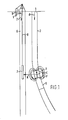
- Fig. 1 the field test was carried out by installing in a target well 1 a casing string 2 comprising a casing section 3 which has been magnetized by traversing the section 3 in axial direction through the central opening of an electric coil.
- the magnetized casing section 3 was a normal N80 grade steel casing section having a length of 12.74 m and an outer diameter of 0.34Am.
- the magnetized casing section was installed on top of a non-magnetic casing section 5 at the nearpoint between the target well 1 and a nearby reference well 6.
- the separation distance R between the two wells at the centre C of the magnetized casing section 3 was about 6 m.
- the position of the two wells relative to each other was accurately surveyed by inertial navigation survey equipment.
- the centre of the magnetized casing section 3 was located at a depth of about 500 m in the target well 1 such that at the base of the magnetized section 3 a South monopole S and at the top thereof a North monopole N is located. Accordingly toroidal magnetic field lines F develop between the poles N and S.
- a magnetic surveying tool 7 consisting of solid state magnetic sensors was run on wireline 8 in an uncased hole section of the reference well 6. Close-spaced magnetic measurements were taken along the longitudinal axis z of the reference well 6.
- the raw magnetic surveying data obtained by the tool 7 were corrected for tool rotation and the influence of the Earth's magnetic field.
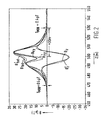
- Fig. 2 The magnitude of the remaining measured magnetic field components in axial direction (B z ) and cross-axial direction (B xy ) with depth z in the reference well 6 is plotted in Fig. 2 (solid lines).
- the distance R to the target well 1 could be determined to within ⁇ 0.5 m.
- the direction could be determined to within 2°.
- the model could be used to estimate the range at which the target well 1 could ultimately have been detected.
- the accuracy of the surveying tool 7 was !about 0.2 ⁇ T. Measured remaining magnetic fields exceeding this value, indicate a magnetic anomaly.
- T 0.4 ⁇ T
- the magnetized casing joint can be detected at least up to about 30 m.
- magnetic poles can be detected at distances over 30 m, although then only qualitative information can be derived about distance and direction.
- the high degree of magnetization obtained by the method according to the invention is caused by the fact that within the central opening of an electric coil a very strong magnetic field can be created and that in a direction co-axial to the central axis of the opening the orientation of the magnetic flux remains identical. In this manner it is possible to magnetize a well casing section to a pole strength of about 13000 ⁇ Wb, which is close to the saturation field strength of steel.
- the same coil can be used to demagnetize sections located adjacent to the magnetized casing section by moving these sections in axial direction through the coil while passing an alternating current through the coil.
- the field test further revealed that the applicability of a theoretical model to describe the behaviour of a magnetic field around an idealized magnetic dipole allows the location of the magnetized casing section, in terms of distance and direction from the reference well, to be accurately determined.
- Said one magnetic dipole may be created by magnetizing one casing section only or by magnetizing a plurality of casing sections and interconnecting them such that a string of magnetized sections is created through which a magnetic flux is oriented in one direction only.
- the coil may be held stationary to the earth while the casing section is moved through the central opening of the coil.
- the coil may be mounted on top of a wellhead while the casing section is moved in a vertical direction through the coil. If the section is moved downwardly through the coil during the magnetization process it is preferred to raise it subsequently from the well in order to measure the pole strength of the magnetic field around the magnetized section before lowering the entire casing string into the well and cementing it in place.
- Suitable alternative magnetic sources are e.g. a large Helmholtz coil arrangement, or the arrangement of strong magnets of opposite polarity at opposite ends of the section.
- any other assembly of well tubulars such as production liners or a production string, may be magnetized as well.
- the string of well tubulars is made of a non-magnetizable material, such as plastic, then an elongate section made of ferromagnetic material, such as a steel strip or sleeve may be magnetized by the method according to the invention and attached to a selected portion of the string.
Abstract
Description
- The invention relates to a method of magnetizing a string of well tubulars along at least part of the length thereof.
- During drilling of deep wells for oil and gas production precise control of the path followed by the well is difficult so that it is difficult to know the exact location of the well at a given depth. This is of particular concern if in case of a well blow-out a relief well must be drilled to intersect the blowing well at a subsurface location.
- It is known in the art to magnetize well tubulars, such as a well casing, so as to create a magnetic target that can be detected by magnetic sensors in a relief well in case of a well blow-out. U.S. patent Nos. 4,458,767 and 4,465,140 disclose a method of magnetizing a well casing by traversing an internal magnetizer along and within the casing while periodically reversing the direction of magnetic field to create a plurality of flux leakage points along the casing. A disadvantage of the known method is that the internal magnetic source creates a magnetic field of which the toroidal magnetic flux lines are scattered when they pass through the wall of the casing, thereby reducing the effectiveness of the magnetisation. In accordance with the known method it appeared possible to magnetize the casing to a magnetic pole strength up to 10⁵γft² (≈ 10 µWb).
- The strength of the magnetic field surrounding a magnetic pole can be estimated by the following formula:
B =
in which: B = measured magnetic field strength (µT) at a location located at a distance R (m) from the magnetic pole and
P = magnetic pole strength (µWb). - As the sensitivity of magnetic sensors currently available for borehole surveying operations is such that they can detect magnetic field strength variations of more than about 0.05 µT it can be calculated that the detection range of the magnetic field around a casing magnetized by the known method is limited to a distance of less than about 4 m from the magnetized casing.
- Although during well surveying operations sometimes much higher magnetic pole strengths, incidentally up to more than 2000 µWb, have been measured on well tubulars it was found that this coincidentally high "spontaneous" pole strength is highly unpredictable.
- Thus there still is a need for a more powerful and accurate method for magnetization of well tubulars which enables determining on the basis of the magnetic field strength in the relief well the direction and distance of a target well in which a blow-out may have occurred. This method should remove the unpredictable magnetization of the casing or other well tubulars involved. Moreover, such a method must be simple so that it can be easily used under adverse field conditions and must provide strongly magnetized well tubulars, since it is extremely important that a well in which a blow-out has occurred be quickly located and plugged not only to protect personnel but also because drilling of a relief well is an expensive and hazardous operation and any delay in obtaining the needed information on the position of the target well can be costly.
- Accordingly it is an object of the present invention to provide a simple but accurate method of strongly magnetizing at least part of a string of well tubulars such that a magnetic field emanated by the magnetized tubulars can be detected at a great distance from these tubulars.
- It is a further object of the present invention to provide a method of strongly magnetizing at least part of a string of well tubulars to a predetermined pole strength.
- Briefly, the method of the present invention includes the steps of:
- selecting an elongate ferromagnetic section of the string which is suitable to be magnetized,
- creating a magnetic field having flux lines which pass in a substantially longitudinal direction through said section, thereby magnetizing said section such that it has opposed magnetic poles having a pole strength of more than 3000 µWb,
- mating said magnetized section with other sections of the string, and
- lowering the string into a borehole. - Most preferably said magnetic field is created by passing a direct current through an electric coil having a central opening in which the magnetic flux lines have a substantially parallel orientation, wherein the step of magnetizing said elongate ferromagnetic section is carried out by traversing the section in longitudinal direction through the central opening of the coil.
- If the string of well tubulars consists of a steel casing or drillpipe string then a selected section of the string may be magnetized by passing the section through the coil. If the string of well tubulars, however, is made of a non-magnetisable material, such as plastic, then an elongate section consisting of a strip or sleeve of ferromagnetic material may be magnetized by the method according to the invention and attached to a selected portion of the string. Said ferromagnetic section may be magnetized either before or after attaching the section to said selected portion of the string.
- The invention will now be explained in more detail, by way of example with reference to the accompanying drawings, in which:
- Fig. 1 is a schematic sketch of a reference well and a target well which contains a casing section magnetized in accordance with the method according to the invention.
- Fig. 2 is a plot of measured and theoretical axial (Bz, B) and cross-axial (Bxy, B
 ) magnetic field strengths in the reference well resulting from the magnetic field emanated by the magnetized casing section in the target well.
- Field experiments have been carried out to verify the range at which a magnetic field emanated by a casing section magnetized by the method according to the invention can be detected.
- As illustrated in Fig. 1 the field test was carried out by installing in a target well 1 a casing string 2 comprising a
casing section 3 which has been magnetized by traversing thesection 3 in axial direction through the central opening of an electric coil. Themagnetized casing section 3 was a normal N80 grade steel casing section having a length of 12.74 m and an outer diameter of 0.34Am. - During magnetization the electric coil was moved in axial direction along the casing section. The magnetization resulted in magnetic pole strength in the order of 13000 µWb. The magnetized casing section was installed on top of a
non-magnetic casing section 5 at the nearpoint between the target well 1 and a nearby reference well 6. - The separation distance R between the two wells at the centre C of the
magnetized casing section 3 was about 6 m. The position of the two wells relative to each other was accurately surveyed by inertial navigation survey equipment. - The centre of the
magnetized casing section 3 was located at a depth of about 500 m in the target well 1 such that at the base of the magnetized section 3 a South monopole S and at the top thereof a North monopole N is located. Accordingly toroidal magnetic field lines F develop between the poles N and S. - A
magnetic surveying tool 7 consisting of solid state magnetic sensors was run on wireline 8 in an uncased hole section of the reference well 6. Close-spaced magnetic measurements were taken along the longitudinal axis z of the reference well 6. - The raw magnetic surveying data obtained by the
tool 7 were corrected for tool rotation and the influence of the Earth's magnetic field. - The magnitude of the remaining measured magnetic field components in axial direction (Bz) and cross-axial direction (Bxy) with depth z in the reference well 6 is plotted in Fig. 2 (solid lines). In Fig. 2 the magnitude of the total magnetic field Btot, calculated on the basis of the formula Btot = √
Bxy²+Bz² , is plotted as well. - On the basis of the field results a theoretical model of the magnetization on the casing was constructed. The model basically assumes a South monopole at the base of the magnetized casing section (d=506 m) and a North monopole, of reduced strength, at the top of the joint (d=493 m). In Fig. 2 the field B8tot predicted by the theoretical model and the axial (B) and cross-axial (B
 ) components thereof (dashed lines) are compared with the measured field Btot and the axial (Bz) and cross-axial (Bxy) components thereof. A good match may be seen, indicating the validity of this model to describe the magnetic field behaviour.
- By making a least squares comparison between the model and the field data, it was found that the distance R to the target well 1 could be determined to within ±0.5 m. The direction could be determined to within 2°.
- The model could be used to estimate the range at which the target well 1 could ultimately have been detected. The accuracy of the
surveying tool 7 was !about 0.2 µT. Measured remaining magnetic fields exceeding this value, indicate a magnetic anomaly. If a threshold value T of 0.4 µT is applied to the data, then according to the model, the magnetized casing joint can be detected at least up to about 30 m. In Fig. 2 it can be seen that at z=530 m and at z=470 m, i.e. about 30 m away "from the centre C of the magnetized joint (d=500 m), there is still a clear influence on the Btot and Bz values. - Under favourable conditions magnetic poles can be detected at distances over 30 m, although then only qualitative information can be derived about distance and direction.
- The field test revealed that by magnetizing a casing section by moving it through the central opening of an electric coil a high magnetic pole strength of about 13000 µWb can be obtained. The high degree of magnetization obtained by the method according to the invention is caused by the fact that within the central opening of an electric coil a very strong magnetic field can be created and that in a direction co-axial to the central axis of the opening the orientation of the magnetic flux remains identical. In this manner it is possible to magnetize a well casing section to a pole strength of about 13000 µWb, which is close to the saturation field strength of steel. The same coil can be used to demagnetize sections located adjacent to the magnetized casing section by moving these sections in axial direction through the coil while passing an alternating current through the coil. By arranging a series of magnetized and demagnetized casing sections in a known pattern in a well it is possible to mark the casing magnetically in a known code.
- The field test further revealed that the applicability of a theoretical model to describe the behaviour of a magnetic field around an idealized magnetic dipole allows the location of the magnetized casing section, in terms of distance and direction from the reference well, to be accurately determined. In order to avoid complications in the description of the theoretical magnetic field and to avoid weakening of the measured magnetic field by interference with magnetic fields emanated by other magnetic sources it is preferred to create only one magnetic dipole or a plurality of widely spaced dipoles rather than a plurality of closely spaced dipoles along the length in the casing string.
- Said one magnetic dipole may be created by magnetizing one casing section only or by magnetizing a plurality of casing sections and interconnecting them such that a string of magnetized sections is created through which a magnetic flux is oriented in one direction only.
- If the casing section is magnetized by moving the section through the coil the coil may be held stationary to the earth while the casing section is moved through the central opening of the coil. The coil may be mounted on top of a wellhead while the casing section is moved in a vertical direction through the coil. If the section is moved downwardly through the coil during the magnetization process it is preferred to raise it subsequently from the well in order to measure the pole strength of the magnetic field around the magnetized section before lowering the entire casing string into the well and cementing it in place.
- It will be understood that instead of using an electric coil for magnetizing the well tubulars other magnetic sources may be used as well, provided that these sources create during the magnetization process a magnetic field of which the flux lines pass in a substantially longitudinal direction through the casing wall. Suitable alternative magnetic sources are e.g. a large Helmholtz coil arrangement, or the arrangement of strong magnets of opposite polarity at opposite ends of the section.
- It will further be understood that instead of magnetizing a well casing or drill string any other assembly of well tubulars, such as production liners or a production string, may be magnetized as well. If the string of well tubulars is made of a non-magnetizable material, such as plastic, then an elongate section made of ferromagnetic material, such as a steel strip or sleeve may be magnetized by the method according to the invention and attached to a selected portion of the string.
Claims (11)
- selecting an elongate ferromagnetic section of the string which is suitable to be magnetized,
- creating a magnetic field having flux lines which pass in a substantially longitudinal direction through said section, thereby magnetizing said section such that it has opposed magnetic poles having a pole strength of more than 3000 µWb,
- mating said magnetized section with other sections of the string, and
- lowering the string into a borehole.
Applications Claiming Priority (2)
| Application Number | Priority Date | Filing Date | Title |
|---|---|---|---|
| GB878718041A GB8718041D0 (en) | 1987-07-30 | 1987-07-30 | Magnetizing well tubulars |
| GB8718041 | 1987-07-30 |
Publications (3)
| Publication Number | Publication Date |
|---|---|
| EP0301671A2 true EP0301671A2 (en) | 1989-02-01 |
| EP0301671A3 EP0301671A3 (en) | 1990-04-18 |
| EP0301671B1 EP0301671B1 (en) | 1992-04-01 |
Family
ID=10621529
Family Applications (1)
| Application Number | Title | Priority Date | Filing Date |
|---|---|---|---|
| EP88201635A Expired - Lifetime EP0301671B1 (en) | 1987-07-30 | 1988-07-28 | Method of magnetizing well tubulars |
Country Status (7)
| Country | Link |
|---|---|
| EP (1) | EP0301671B1 (en) |
| AU (1) | AU607522B2 (en) |
| CA (1) | CA1333412C (en) |
| DE (1) | DE3869690D1 (en) |
| ES (1) | ES2030159T3 (en) |
| GB (1) | GB8718041D0 (en) |
| NO (1) | NO173523C (en) |
Cited By (8)
| Publication number | Priority date | Publication date | Assignee | Title |
|---|---|---|---|---|
| WO1995019490A1 (en) * | 1994-01-13 | 1995-07-20 | Shell Internationale Research Maatschappij B.V. | Method of creating a borehole in an earth formation |
| EP1076155A1 (en) * | 1999-08-09 | 2001-02-14 | Shell Internationale Researchmaatschappij B.V. | Coding system for use in a wellbore |
| US6698516B2 (en) * | 2001-02-16 | 2004-03-02 | Scientific Drilling International | Method for magnetizing wellbore tubulars |
| WO2006065745A1 (en) * | 2004-12-13 | 2006-06-22 | Baker Hughes Incorporated | A method and apparatus for demagnetizing a borehole |
| GB2421795A (en) * | 2004-12-20 | 2006-07-05 | Pathfinder Energy Services Inc | Magnetisation of target well casing string tubulars for enhanced passive ranging |
| CN101567245B (en) * | 2009-03-03 | 2011-04-20 | 西部钻探测井公司 | Down-hole casing tube demagnetizer and using method thereof |
| US7969150B2 (en) | 2004-12-13 | 2011-06-28 | Baker Hughes Incorporated | Demagnetizer to eliminate residual magnetization of wellbore wall produced by nuclear magnetic resonance logs |
| WO2014044628A1 (en) * | 2012-09-18 | 2014-03-27 | Shell Internationale Research Maatschappij B.V. | Method of orienting a second borehole relative to a first borehole |
Families Citing this family (6)
| Publication number | Priority date | Publication date | Assignee | Title |
|---|---|---|---|---|
| US8026722B2 (en) | 2004-12-20 | 2011-09-27 | Smith International, Inc. | Method of magnetizing casing string tubulars for enhanced passive ranging |
| US7538650B2 (en) | 2006-07-17 | 2009-05-26 | Smith International, Inc. | Apparatus and method for magnetizing casing string tubulars |
| US7712519B2 (en) | 2006-08-25 | 2010-05-11 | Smith International, Inc. | Transverse magnetization of casing string tubulars |
| US7617049B2 (en) | 2007-01-23 | 2009-11-10 | Smith International, Inc. | Distance determination from a magnetically patterned target well |
| US8010290B2 (en) | 2007-05-03 | 2011-08-30 | Smith International, Inc. | Method of optimizing a well path during drilling |
| US9238959B2 (en) | 2010-12-07 | 2016-01-19 | Schlumberger Technology Corporation | Methods for improved active ranging and target well magnetization |
Citations (4)
| Publication number | Priority date | Publication date | Assignee | Title |
|---|---|---|---|---|
| US3406766A (en) * | 1966-07-07 | 1968-10-22 | Henderson John Keller | Method and devices for interconnecting subterranean boreholes |
| US4072200A (en) * | 1976-05-12 | 1978-02-07 | Morris Fred J | Surveying of subterranean magnetic bodies from an adjacent off-vertical borehole |
| US4458767A (en) * | 1982-09-28 | 1984-07-10 | Mobil Oil Corporation | Method for directionally drilling a first well to intersect a second well |
| US4465140A (en) * | 1982-09-28 | 1984-08-14 | Mobil Oil Corporation | Method for the magnetization of well casing |
Family Cites Families (2)
| Publication number | Priority date | Publication date | Assignee | Title |
|---|---|---|---|---|
| AU516975B2 (en) * | 1977-12-08 | 1981-07-02 | Commonwealth Scientific And Industrial Research Organisation | Magnetic marking |
| EP0104854A3 (en) * | 1982-09-28 | 1985-04-10 | Mobil Oil Corporation | Method for the magnetization of well casing |
-
1987
- 1987-07-30 GB GB878718041A patent/GB8718041D0/en active Pending
-
1988
- 1988-07-26 CA CA000573019A patent/CA1333412C/en not_active Expired - Fee Related
- 1988-07-28 DE DE8888201635T patent/DE3869690D1/en not_active Expired - Lifetime
- 1988-07-28 EP EP88201635A patent/EP0301671B1/en not_active Expired - Lifetime
- 1988-07-28 ES ES198888201635T patent/ES2030159T3/en not_active Expired - Lifetime
- 1988-07-28 NO NO883350A patent/NO173523C/en not_active IP Right Cessation
- 1988-07-28 AU AU20119/88A patent/AU607522B2/en not_active Expired
Patent Citations (4)
| Publication number | Priority date | Publication date | Assignee | Title |
|---|---|---|---|---|
| US3406766A (en) * | 1966-07-07 | 1968-10-22 | Henderson John Keller | Method and devices for interconnecting subterranean boreholes |
| US4072200A (en) * | 1976-05-12 | 1978-02-07 | Morris Fred J | Surveying of subterranean magnetic bodies from an adjacent off-vertical borehole |
| US4458767A (en) * | 1982-09-28 | 1984-07-10 | Mobil Oil Corporation | Method for directionally drilling a first well to intersect a second well |
| US4465140A (en) * | 1982-09-28 | 1984-08-14 | Mobil Oil Corporation | Method for the magnetization of well casing |
Non-Patent Citations (1)
| Title |
|---|
| Offshore, Vol. 48 (1988), April, No. 4, Tulsa, Oklahoma, USA, p. 23 LeBlanc: Casing magnetization aids home-in for relief well * |
Cited By (18)
| Publication number | Priority date | Publication date | Assignee | Title |
|---|---|---|---|---|
| WO1995019490A1 (en) * | 1994-01-13 | 1995-07-20 | Shell Internationale Research Maatschappij B.V. | Method of creating a borehole in an earth formation |
| US5541517A (en) * | 1994-01-13 | 1996-07-30 | Shell Oil Company | Method for drilling a borehole from one cased borehole to another cased borehole |
| CN1056906C (en) * | 1994-01-13 | 2000-09-27 | 国际壳牌研究有限公司 | Method of creating a borehole in an earth formation |
| EP1076155A1 (en) * | 1999-08-09 | 2001-02-14 | Shell Internationale Researchmaatschappij B.V. | Coding system for use in a wellbore |
| US6698516B2 (en) * | 2001-02-16 | 2004-03-02 | Scientific Drilling International | Method for magnetizing wellbore tubulars |
| GB2435795B (en) * | 2004-12-13 | 2009-01-14 | Baker Hughes Inc | A Method and apparatus for demagnetizing a borehole |
| GB2435795A (en) * | 2004-12-13 | 2007-09-05 | Baker Hughes Inc | A Method and apparatus for demagnetizing a borehole |
| WO2006065745A1 (en) * | 2004-12-13 | 2006-06-22 | Baker Hughes Incorporated | A method and apparatus for demagnetizing a borehole |
| US7913756B2 (en) | 2004-12-13 | 2011-03-29 | Baker Hughes Incorporated | Method and apparatus for demagnetizing a borehole |
| US7969150B2 (en) | 2004-12-13 | 2011-06-28 | Baker Hughes Incorporated | Demagnetizer to eliminate residual magnetization of wellbore wall produced by nuclear magnetic resonance logs |
| US8245771B2 (en) | 2004-12-13 | 2012-08-21 | Baker Hughes Incorporated | Method and apparatus for demagnetizing a borehole |
| GB2421795A (en) * | 2004-12-20 | 2006-07-05 | Pathfinder Energy Services Inc | Magnetisation of target well casing string tubulars for enhanced passive ranging |
| GB2421795B (en) * | 2004-12-20 | 2009-02-25 | Pathfinder Energy Services Inc | Magnetization of target well casing string tubulars for enhanced passive ranging |
| CN101567245B (en) * | 2009-03-03 | 2011-04-20 | 西部钻探测井公司 | Down-hole casing tube demagnetizer and using method thereof |
| WO2014044628A1 (en) * | 2012-09-18 | 2014-03-27 | Shell Internationale Research Maatschappij B.V. | Method of orienting a second borehole relative to a first borehole |
| GB2521297A (en) * | 2012-09-18 | 2015-06-17 | Shell Int Research | Method of orienting a second borehole relative to a first borehole |
| GB2521297B (en) * | 2012-09-18 | 2017-09-06 | Shell Int Research | Method of orienting a second borehole relative to a first borehole |
| US9932819B2 (en) | 2012-09-18 | 2018-04-03 | Shell Oil Company | Method of orienting a second borehole relative to a first borehole |
Also Published As
| Publication number | Publication date |
|---|---|
| DE3869690D1 (en) | 1992-05-07 |
| NO883350L (en) | 1989-01-31 |
| EP0301671A3 (en) | 1990-04-18 |
| ES2030159T3 (en) | 1992-10-16 |
| NO173523C (en) | 1993-12-22 |
| NO173523B (en) | 1993-09-13 |
| EP0301671B1 (en) | 1992-04-01 |
| GB8718041D0 (en) | 1987-09-03 |
| NO883350D0 (en) | 1988-07-28 |
| CA1333412C (en) | 1994-12-06 |
| AU607522B2 (en) | 1991-03-07 |
| AU2011988A (en) | 1989-02-02 |
Similar Documents
| Publication | Publication Date | Title |
|---|---|---|
| CA1186733A (en) | Well casing detector system and method | |
| US4458767A (en) | Method for directionally drilling a first well to intersect a second well | |
| US7095223B2 (en) | Method of locating an anomaly in a tubular member in a well | |
| US4572293A (en) | Method of placing magnetic markers on collarless cased wellbores | |
| CA2862256C (en) | Magnetic ranging tool and method | |
| EP0301671B1 (en) | Method of magnetizing well tubulars | |
| CA1234870A (en) | Method for preventing the drilling of a new well into one of a plurality of production wells | |
| US6698516B2 (en) | Method for magnetizing wellbore tubulars | |
| US4629991A (en) | Methods and apparatus for detecting tubular defects having a plurality of expandable arcuate segments | |
| CA2534600A1 (en) | Method for locating casing joints using measurement while drilling tool | |
| AU2016219651B2 (en) | Determining the depth and orientation of a feature in a wellbore | |
| US4715442A (en) | Apparatus for servicing tubular strings in subterranean wells | |
| US20200257014A1 (en) | Using Magnetism To Evaluate Tubing String Integrity In A Wellbore With Multiple Tubing Strings | |
| WO2007015087A1 (en) | Method of determining features of downhole apparatus | |
| US6076268A (en) | Tool orientation with electronic probes in a magnetic interference environment | |
| CA1228639A (en) | Method for the magnetization of well casing | |
| US10422198B2 (en) | Magnetic ranging from behind a magnetic shield | |
| CA3146320A1 (en) | Magnetic ranging to an axially magnetized magnetic source | |
| CA1237764A (en) | Method for the magnetization of well casing | |
| CN114856550A (en) | Device and method for accurately positioning petroleum casing pipe based on geomagnetic anomaly marker |
Legal Events
| Date | Code | Title | Description |
|---|---|---|---|
| PUAI | Public reference made under article 153(3) epc to a published international application that has entered the european phase |
Free format text: ORIGINAL CODE: 0009012 |
|
| AK | Designated contracting states |
Kind code of ref document: A2 Designated state(s): DE ES FR GB IT NL |
|
| PUAL | Search report despatched |
Free format text: ORIGINAL CODE: 0009013 |
|
| AK | Designated contracting states |
Kind code of ref document: A3 Designated state(s): DE ES FR GB IT NL |
|
| 17P | Request for examination filed |
Effective date: 19900803 |
|
| 17Q | First examination report despatched |
Effective date: 19910816 |
|
| GRAA | (expected) grant |
Free format text: ORIGINAL CODE: 0009210 |
|
| AK | Designated contracting states |
Kind code of ref document: B1 Designated state(s): DE ES FR GB IT NL |
|
| ITF | It: translation for a ep patent filed |
Owner name: JACOBACCI & PERANI S.P.A. |
|
| REF | Corresponds to: |
Ref document number: 3869690 Country of ref document: DE Date of ref document: 19920507 |
|
| ET | Fr: translation filed | ||
| REG | Reference to a national code |
Ref country code: ES Ref legal event code: FG2A Ref document number: 2030159 Country of ref document: ES Kind code of ref document: T3 |
|
| PLBE | No opposition filed within time limit |
Free format text: ORIGINAL CODE: 0009261 |
|
| STAA | Information on the status of an ep patent application or granted ep patent |
Free format text: STATUS: NO OPPOSITION FILED WITHIN TIME LIMIT |
|
| 26N | No opposition filed | ||
| REG | Reference to a national code |
Ref country code: GB Ref legal event code: IF02 |
|
| PGFP | Annual fee paid to national office [announced via postgrant information from national office to epo] |
Ref country code: DE Payment date: 20070726 Year of fee payment: 20 |
|
| PGFP | Annual fee paid to national office [announced via postgrant information from national office to epo] |
Ref country code: ES Payment date: 20070727 Year of fee payment: 20 |
|
| PGFP | Annual fee paid to national office [announced via postgrant information from national office to epo] |
Ref country code: GB Payment date: 20070622 Year of fee payment: 20 |
|
| PGFP | Annual fee paid to national office [announced via postgrant information from national office to epo] |
Ref country code: IT Payment date: 20070609 Year of fee payment: 20 |
|
| PGFP | Annual fee paid to national office [announced via postgrant information from national office to epo] |
Ref country code: NL Payment date: 20070725 Year of fee payment: 20 |
|
| PGFP | Annual fee paid to national office [announced via postgrant information from national office to epo] |
Ref country code: FR Payment date: 20070510 Year of fee payment: 20 |
|
| REG | Reference to a national code |
Ref country code: GB Ref legal event code: PE20 Expiry date: 20080727 |
|
| NLV7 | Nl: ceased due to reaching the maximum lifetime of a patent |
Effective date: 20080728 |
|
| REG | Reference to a national code |
Ref country code: ES Ref legal event code: FD2A Effective date: 20080729 |
|
| PG25 | Lapsed in a contracting state [announced via postgrant information from national office to epo] |
Ref country code: NL Free format text: LAPSE BECAUSE OF EXPIRATION OF PROTECTION Effective date: 20080728 |
|
| PG25 | Lapsed in a contracting state [announced via postgrant information from national office to epo] |
Ref country code: GB Free format text: LAPSE BECAUSE OF EXPIRATION OF PROTECTION Effective date: 20080727 |
|
| PG25 | Lapsed in a contracting state [announced via postgrant information from national office to epo] |
Ref country code: ES Free format text: LAPSE BECAUSE OF EXPIRATION OF PROTECTION Effective date: 20080729 |