EP0301909A2 - Apparatus for rapidly accessing a large data base - Google Patents
Apparatus for rapidly accessing a large data base Download PDFInfo
- Publication number
- EP0301909A2 EP0301909A2 EP88307061A EP88307061A EP0301909A2 EP 0301909 A2 EP0301909 A2 EP 0301909A2 EP 88307061 A EP88307061 A EP 88307061A EP 88307061 A EP88307061 A EP 88307061A EP 0301909 A2 EP0301909 A2 EP 0301909A2
- Authority
- EP
- European Patent Office
- Prior art keywords
- read
- disc
- data
- address
- track
- Prior art date
- Legal status (The legal status is an assumption and is not a legal conclusion. Google has not performed a legal analysis and makes no representation as to the accuracy of the status listed.)
- Granted
Links
Images


Classifications
-
- B—PERFORMING OPERATIONS; TRANSPORTING
- B07—SEPARATING SOLIDS FROM SOLIDS; SORTING
- B07C—POSTAL SORTING; SORTING INDIVIDUAL ARTICLES, OR BULK MATERIAL FIT TO BE SORTED PIECE-MEAL, e.g. BY PICKING
- B07C3/00—Sorting according to destination
-
- G—PHYSICS
- G11—INFORMATION STORAGE
- G11B—INFORMATION STORAGE BASED ON RELATIVE MOVEMENT BETWEEN RECORD CARRIER AND TRANSDUCER
- G11B27/00—Editing; Indexing; Addressing; Timing or synchronising; Monitoring; Measuring tape travel
- G11B27/002—Programmed access in sequence to a plurality of record carriers or indexed parts, e.g. tracks, thereof, e.g. for editing
-
- G—PHYSICS
- G11—INFORMATION STORAGE
- G11B—INFORMATION STORAGE BASED ON RELATIVE MOVEMENT BETWEEN RECORD CARRIER AND TRANSDUCER
- G11B27/00—Editing; Indexing; Addressing; Timing or synchronising; Monitoring; Measuring tape travel
- G11B27/10—Indexing; Addressing; Timing or synchronising; Measuring tape travel
- G11B27/102—Programmed access in sequence to addressed parts of tracks of operating record carriers
- G11B27/105—Programmed access in sequence to addressed parts of tracks of operating record carriers of operating discs
-
- G—PHYSICS
- G11—INFORMATION STORAGE
- G11B—INFORMATION STORAGE BASED ON RELATIVE MOVEMENT BETWEEN RECORD CARRIER AND TRANSDUCER
- G11B27/00—Editing; Indexing; Addressing; Timing or synchronising; Monitoring; Measuring tape travel
- G11B27/10—Indexing; Addressing; Timing or synchronising; Measuring tape travel
- G11B27/19—Indexing; Addressing; Timing or synchronising; Measuring tape travel by using information detectable on the record carrier
- G11B27/28—Indexing; Addressing; Timing or synchronising; Measuring tape travel by using information detectable on the record carrier by using information signals recorded by the same method as the main recording
- G11B27/32—Indexing; Addressing; Timing or synchronising; Measuring tape travel by using information detectable on the record carrier by using information signals recorded by the same method as the main recording on separate auxiliary tracks of the same or an auxiliary record carrier
- G11B27/327—Table of contents
- G11B27/329—Table of contents on a disc [VTOC]
-
- G—PHYSICS
- G11—INFORMATION STORAGE
- G11B—INFORMATION STORAGE BASED ON RELATIVE MOVEMENT BETWEEN RECORD CARRIER AND TRANSDUCER
- G11B7/00—Recording or reproducing by optical means, e.g. recording using a thermal beam of optical radiation by modifying optical properties or the physical structure, reproducing using an optical beam at lower power by sensing optical properties; Record carriers therefor
- G11B7/002—Recording, reproducing or erasing systems characterised by the shape or form of the carrier
- G11B7/0037—Recording, reproducing or erasing systems characterised by the shape or form of the carrier with discs
-
- G—PHYSICS
- G11—INFORMATION STORAGE
- G11B—INFORMATION STORAGE BASED ON RELATIVE MOVEMENT BETWEEN RECORD CARRIER AND TRANSDUCER
- G11B2220/00—Record carriers by type
- G11B2220/20—Disc-shaped record carriers
- G11B2220/21—Disc-shaped record carriers characterised in that the disc is of read-only, rewritable, or recordable type
- G11B2220/213—Read-only discs
-
- G—PHYSICS
- G11—INFORMATION STORAGE
- G11B—INFORMATION STORAGE BASED ON RELATIVE MOVEMENT BETWEEN RECORD CARRIER AND TRANSDUCER
- G11B2220/00—Record carriers by type
- G11B2220/20—Disc-shaped record carriers
- G11B2220/25—Disc-shaped record carriers characterised in that the disc is based on a specific recording technology
- G11B2220/2537—Optical discs
- G11B2220/2545—CDs
Definitions
- This invention relates to an apparatus for accessing a relatively large data base, preferably in one seek.
- USPS United States Postal Service
- OCR optical character reading
- the USPS employs two types of automatic sorting equipment.
- this first type the characters of the address block are read by optical character reader (OCR) systems.
- OCR optical character reader
- existing sorters the bottom line containing the city, state and zip code is read. From this data a barcode is marked on the envelope by an ink jet printer.
- This barcode can be read by automatic sorters of the second type, which are less expensive since they are not equipped with the OCR system.
- the USPS system contains many more sorters of the second type than of the first type.
- Each such letter sorter requires a data base which contains the destination addresses corresponding to the nine digit (zip+4) or eleven digit (zip+6) zip codes.
- the nine digit zip code defines the ranges of addresses, such as a side of a street, or a floor of an office building.
- the USPS maintains a file of standard address ranges for the zip+4 codes, which consists of about 29 million records requiring approximately 3 gigabytes for storage.
- a standard address is that assigned by the USPS. Individual postal patrons may inscribe mailpieces with variations on or additions to the standard address. These variations are a problem in the design of OCR systems for USPS.
- the present inventor recognises a need to provide rapid access to the file of standard addresses.
- the eleven digit zip code defines all the specific mail destinations in the country, and consists of some 86 million records. An additional factor is that there are approximately 40 million changes of addresses each year; the change of address file is kept for eighteen months. Thus, there are an average of about 110 thousand changes of address per day. The data base to retain these addresses for eighteen months contains 60 million records.
- the letter sorters process twelve letters per second (80 millisec per letter). Further, the data base containing all of the addresses must be accessed at this rate of a continued sustained basis. It is intended that there by 650 letter sorters on a nation wide basis. Such sorters will be located at 250 sectional centers. Letters entering the center are to be marked with a bar code containing the nine or eleven zip digits; thereafter, simple sorters will read the code. Each of the 650 data bases is a duplicate containing the addresses for the entire country.
- Magnetic disc recording systems of requisite capacity are standard features of large computer systems. These are controlled by data base software which enable continuous incremental updates of the records by many users. The consequence of this procedure is that the distribution of data on a disc becomes progressively more complex and multiple seeks are necessary to find specific items. Thus, even though the access time for a high performance disc may be as low as 18 milliseconds (ms), so many accesses are required that the 80ms (12 per second) goal cannot be met.
- Such a data base can be updated periodically at a central site and copies distributed to local cites where it can be read but not revised.
- Such data bases can be updated, published and distributed as wholes and local updating may be by complete replacement of the entire data base. Because any specific issue of the data base is static, it can be organized in a simple manner such that one seek to a track and scan of that track will find any record.
- CD-ROM compact disc read only memory
- D-1 format digital video tape
- CD-ROM compact disc read only memory
- CD-ROM refers to the use of compact audio disc technology for the distribution and reproduction of digital data. A single such disc contains in excess of 0.5 gigibytes (GB) of user data, after system overhead and error correction are included.
- Digital video tape refers to the use of helical scan video recording technology to record digital signals. The recording density is significantly greater than on conventional computer tapes.
- CD-ROMS's are conventionally recorded with a spiral track at constant linear velocity.
- the recorded data rate is constant and the disc speed must change with the radial position of the recording or read head.
- the read head contains a semiconductor laser and sensors which provide signals for focus and tracking servos, as well as data readout.
- Commerical CD-ROM players are intended for personal computers and feature access times of the order of one second, which is impractical for the USPS applications.
- a plurality of read head means are coupled to the drive means for independently accessing and reading data at a plurality of disc locations from anywhere on a given disc at substantially the same constant data rate regardless the difference in actual data rate occurring on the different track portions being read. Control means select and operate the selected read head means.
- a conveyer 11 conveys a serial stream of letters L1-LN or other types of mail for reading by an optical character reader (OCR) 12.
- OCR 12 reads the name, street, city, state and five digit zip code appearing on the face of the letters L1-LN.
- the name, street, city, state and five digit zip code read by the OCR 12 is supplied to system controller and multiplexer 14.
- Multiplexer 14 has a plurality of parallel channel outputs 1A-D, 2A-D - 10A-D. These outputs are applied via multiple lines to CD-ROM controllers for reading data from an array 15 of CD-ROM read systems.
- outputs 1A are applied to controller 16A
- outputs 1B are applied to controller 16B
- outputs 2A-D of multiplexer 14 are respectively applied to a second set of identical controllers 17A-17D wherein outputs 2A are applied to controller 17A, outputs 2B are applied to controller 17B and so on.
- the remaining outputs 3A-D - 10A-D are applied respectively to the remaining sets of controllers 18, 20, 22, 24, 26, 28, 30 and 32 of the system.
- Each of the sets 18-32 comprise four identical controllers which are also identical to controller sets 16A-16D and 17A-17D for receiving inputs from the system control and multiplexer 14.
- Controller 16A operates an actuator 34
- controller 16B operates an actuator 36
- controller 16C operates an actuator 38
- controller 16D operates an actuator 40
- Actuators 34-40 are mechanical devices for radially displacing respective laser read heads 44-50 secured thereto. Actuators 34, 36, 38 and 40 are represented by radial lines relative to CD-ROM drive 42. Actuator 34 is radially aligned with actuator 38 on diametrical opposite sides of the drive 42. Similarly, actuators 36 and 40 are radially aligned normal to actuators 34 and 38. Actuator 34 is coupled to a read head 44, actuator 36 is coupled to read head 46, actuator 38 is coupled to read head 48 and actuator 40 is coupled to read head 50.
- Read heads 44-50 are identical and comprise a laser read mechanism as available in commercially available CD-ROM drive systems. Each controller 16A-16D independently drives and controls the position of its respective corresponding read head 44-50 via the respective actuators 34-40.
- the use of plural read heads with independent actuators and controllers allows overlapping of periods of time to adjust the radial position of the heads as part of a seek operation. This permits the plural heads to be read consecutively without having to allow intervening time periods to adjust read head radial positions.
- a CD-ROM read head and actuator system is associated with each controller 17A-17D and the remaining controller sets 18-32.
- the laser read drive subsystems are identical.
- System control and multiplexer 14 responds to the scan of the address on a given letter L1-LN and activates a selected one of the controllers to access a portion of a disc known a priori to contain the standard address and five+four zip code corresponding to the read letter.
- a CD-ROM disc is on each of the CD-ROM drives. Each disc is part of a data base containing the standard address including the city, state and five+four zip code. As known, the five-digit zip code refers to a destination locality whereas the additional four digit zip code narrows the destination to a given street or carrier route.
- the United States Postal System desires to bar code print the nine-digit zip code (five+four) onto each letter so that the letter may be automatically sorted by the bar code imprinted address by a sorter 52.
- Sorter 52 may be of the first or second types as described above. To do this the controllers for each of the CD-ROM drive systems supply the additional four digit specific zip code in response to the reading of the normal five digit zip code appearing on each letter.
- System control and multiplexer 14 generates from the read address and five-digit zip code an appropriate signal which identifies a particular controller of a particular disc drive system corresponding to that read data. That signal causes the read head of a given drive system to access the standard address and nine-digit zip code information from a given CD-ROM disc driven by that drive system. To perform this access the read head radial position is slewed to the approximate track location using a digital position encoder. The read head is then positioned to the desired track portion by counting tracks. Because conventional CD-ROMs have access time of about 1 to 2 seconds and because the postal system requires accessing of the data base at a rate of 12 items per second, normal CD-ROMs are too slow for this purpose.
- each drive system 42, 43, 45, 47, 49, 51, 53, 57, and 59 each receiving a CD-ROM disc containing a different portion of the standard address and nine-digit zip code data base and by providing each drive system with four read heads it is possible to access the selected addresses and zip codes at an average rate of 12 units/second.
- the number of read heads and thus access channels is a function of the required access time in relation to the required read rate. Access time is the time required to radially position the head plus the time to rotate the disc about one revolution under the head.
- the access time for a disc is a function of the disc rotation speed and head seek time.
- CD-ROMs normally have about 18,000 spirally connected tracks.
- the system control and multiplexer 14 determines which one of the systems 42-59 and which one of the controllers 16A-16D through 32 contains the desired address and generates an appropriate signal. That signal selects the specific read head and given drive system for accessing the data at that selected drive system. How the controllers operate and select the information and how the system controller derives the signal for selecting a given controller is described below in more detail in connection with FIGURE 3.
- the information is applied via line 54 to system control and multiplexer 14.
- the information accessed on a given CD-ROM disc is the standard street address range and corresponding nine-digit zip code.
- multiplexer 14 causes bar code printer 56, which may be a jet ink printer, to print the bar code representing the nine digit zip code on the individual letters such as letter L3.
- representative system 42 includes a disc drive 58 and a CD-ROM disc 60.
- One controller 16A and its corresponding actuator 36 are shown in solid, the remaining controllers and actuators are represented by the broken radial lines 62, 64 and 66.
- Disc 60 contains data which are recorded in a continuous inside out spiral track.
- CD-ROM discs contain data in a series of user data blocks of fixed size alternating with headers containing serial numbers and error detection codes.
- User data files may contain any number of data blocks.
- the length of a file depends on the amount of data in that file and the angular location of the beginning of the file may vary from track to track along the spiral.
- the header information as employed on the disc of the present data base is conventional.
- the access time in a disc recording system has two components, conventionally named seek time and latency time.
- Seek time is that required for the read head to find a specific track, commonly by a generally radial movement (which may be in a straight line or arc).
- Latency time is that required for the disc to rotate to bring the desired data past the read head.
- the latency time is determined by the rotation speed of the disc which in turn is a function of the data density of the track and the data bandwith of the processing circuits.
- latency time may be over 200ms. Seek time must be reduced to tens of milliseconds to achieve the performance goal of 320ms access time.
- a CD-ROM player utilizes a pre-recorded plastic whose tracks are spaced about 1.6 micrometers apart. Because of thermal expansion and manufacturing variations, the exact radial position of a track is initially unknown to the system. In conventional CD-ROM players, specific tracks must be located by a method of successive approximation as described above. The present system provides a means for accessing the disc by each head in 320 milliseconds in on seek.
- Each disc of the data base for example disc 60, is marked with reference indicia 68 and 70.
- Indicium 68 represents an angular reference mark by which the angular position of data from that reference mark is measured by the value of angle ⁇ .
- Indicia 70 divide the disc into small angular increments to provide precise angular location of any point on the disc with reference to the indicia 68.
- Two sensors 72 and 74 are coupled to controller 16A for supplying information relative to the angular position of the reference indicium 68 and for providing information via indicia 70 of the exact angular position of any point on the disc 60.
- Each controller 16A through 16D controllers 32 include sensors such as sensors 72 and 74 for sensing the reference indicia on the corresponding rotating disc.
- the disc drive 58 of system 42 includes a turntable 78 which receives the disc 60 and further includes a drive motor 80 for rotating the table 78 at a constant angular rate.
- Each of the discs 60 as is known comprises static data impressed upon an optically reflective surface and coated with a transparent protective coating.
- the data comprise impressions formed in the reflective coating surface so that the transitions at the beginning and end of each depression form a binary signal representing the data.
- the binary one for example may represent the transition from the bottom of the depression to the disc surface or vice versa whereas a binary zero may represent the bottom of the depression or the disc surface between depressions.
- These depressions are formed in a spiral track.
- the disc may be premastered and pressed in a conventional manner and the distributed to a wide number of local postal sorting stations located throughout the United States.
- the data base comprises a set of ten discs. Each disc is associated with a separate drive system 42. Encoded at the end of the data track of each disc is an indexing table.
- the indexing table comprises a hash index number and the r- ⁇ coordinates of the file headers expressed in radial and angular dimensions.
- the table of coordinates is recorded last on the disc so that its presence does not disturb the locations of the files whose coordinates are calculated from the location of those files.
- the recording of a CD-ROM master is a precision process so that angular and radial location of any data block can be calculated in advance.
- a computer program prepares the database and the data block headers.
- a number is extracted from the address including the street, city, state and five-digit zip code.
- the hash algorithm generates the index number.
- the five digit zip code is concatenated with the address number and the initial letters of a street name. These represent a large digital number which is divided by 180,000 (the number of tracks on the ten discs). The remainder of such division comprises an index position on the spiral track relating to the header block serial number identifying a given file.
- the system control and multiplexer 14 includes computer memory 82.
- the memory 82 stores the hash index table that is read from a given disc 60 when the disc 60 is loaded onto the drive system 42.
- One of the four read heads, e.g., head 46, reads that table and transfers the information to the memory 82 of multiplexer 14 upon command by multiplexer 14.
- Multiplexer 14 includes a buffer memory 84 for storing the name, street, city, state and five digit zip code read by OCR 12. This information is supplied to computer 86 which derives the hashing index number, as discussed above. Since in computer machine language all alpha characters are represented in ASCII character numbers, the letters and digits of the address form a serial set of digits which form can be interpreted as a number from which the hashing alogrithm of the computer 86 derives the hash index as previously explained. The name and address are supplied from the memory 84 to a comparator 88 for reasons to be explained later.
- a processor in multiplexer 14 in response to the index number derived from the name and address read by OCR 12 from a letter L1-LN in the letter stream searches for the corresponding hashed index number in the table of memory 82. That index number corresponds to a given drive system 42-59 (FIGURE 1) and r- ⁇ coordinates which locate the beginning of the file containing that name, address and nine-digit zip code in the disc on that drive system.
- the information is sent via electronic signals on lines 90 to controller 16A.
- the signal on line 90′ is one which activates drive system 42 based on the correspondence of the hash index number to drive 42 in the memory 82.
- the lines 90 represent the lines to a single controller and that similar lines are fed to each of the other controllers corresponding to each read head in the system.
- Multiplexer 14 via a signal such as on line 90′ selects that controller which is to receive the control signals and coordinates for driving the selected read head.
- Actuator control 92 may be a microprocessor for performing various functions to be described.
- One set of inputs to control 92 is the sense signals from sensor 72 and 74 for indicating an angular position of the reference angle ⁇ .
- One output of control 92 drives actuator 36.
- Actuator 36 is a commercially available read head drive for moving the read head 46 back and forth in the radial direction relative to disc 60.
- Read head 46 is commerically available and includes a laser 96 for reading the encoded data on disc 60.
- the laser 96 is on a support 98 which is moved in the radial directions by actuator 36. Coupled to support 98 is a linear position encoder 100.
- Linear position encoder 100 provides a digitally encoded signal representing the position of the laser 96 along the radius r. The position of the laser 96 is also measured by monitoring the track sense line from the disc read electronics 102. This line transmits a plus or minus signal depending on whether the read head is inside or outside a specific track. When searching across the tracks, this signal varies cyclically as it passes over the tracks. By counting the cycles, the number of tracks passed can be determined by an algorithm in actuator control 92.
- the linear position encoder 100 serves to provide information to enable the actuator 36 to slew the read head 46 to within several tracks ahead of the track containing the file of interest. The track count provides additional information to enable the actuator to position the read head 46 at the track of interest.
- Linear position encoder 100 provides a signal to actuator control 92 giving the encoded position information of the radial location of the read head 46.
- the actuator control 92 uses this information from encoder 100 to process the signals from the multiplexer 14 to precisely position the laser 96 where desired in accordance with the given hash index number derived from a given letter.
- control 92 Associated with the read head 46 are the disc read electronics 102 which read the information including sensing the tracks and other housekeeping track and data reading information.
- the control 92 generates a clock signal on line 104 for providing the appropriate data read rate for electronics 102.
- the clock rate on line 104 differs in accordance with the radial distance r sensed by the read head 46 and as interpreted by the electronics 102.
- Included within control 92 is memory 106.
- Memory 106 contains a calibration table which includes the track radial distance r as derived from the memory 82 in multiplexer 14, and which includes the actual distance r′ as measured by position encoder 100 to the actual track represented by the corresponding hash index number. For each such assumed radius r and actual measured radius r′, a clock signal having a frequency f is assigned the r and r′ values. The clock frequency changes as the radial distance r of a given track changes relative to the axis 76 and is computed by the system for each actual r′ measured.
- the table in memory 106 is created as the system is started up.
- the information on the tracks may include self-clocking codes for synchronizing the data read electronics.
- the actuator control 92 includes a microprocessor (not shown) which periodically causes a read head to scan the tracks of its disc 60 to update track r′ information into memory 106 updating the table. This update information may be multiplexed with the normal deployment of the read heads during data seek cycles.
- the reason for updating the track location with the value r′ periodically and for providing the calibration table in memory 106 is to compensate for manufacturing and environmentally caused track location errors. Temperature variations, manufacturing processes, and tolerances in pressing each disc are such that actual locations of the tracks on each disc may change from any predetermined value. Normally there will be local and global errors in the molding process, shrinkage after molding, and thermal expansion and aging effects in use which need to be compensated.
- the disc is thermoplastic material in which these track spacings are approximately 16 microns, which dimension can easily change due to the environmental conditions. Therefore, the radius r of any specific track, that is a turn of the spiral, cannot be precisely known in advance except by a periodic update calibration process.
- the focus servo in a conventional CD-ROM system embodied in the actuator control 92 operates independently of the data tracking.
- a drive signal on lead 90′ is applied to actuator controller 92 selecting system 42.
- the signals applied to actuator control 92 represent and r and ⁇ coordinates for the hash index number derived from the street address on the letter L1 then being read by OCR 12. These coordinates, particularly the r coordinate, is used by the calibration computer 106 to derive the r′ coordinate and determine the data clock frequency f for that r′.
- the actuator control 92 in response to the r′ signal from the calibration computer then causes the encoder 100 to slew the laser 96 of the read head 46 into position.
- the read electronics 102 counts tracks supplying the track count to control 92.
- Control 92 in response to the track count moves laser 96 to the position represented by the distance r′.
- the disc read electronics counts tracks to position the read head 46 at the target track.
- the address information in that file located on the targeted track is then read at the f data rate. Address information is supplied by the disc read electronics 102 to terminal T, which applies that signal to comparator 88.
- Comparator 88 includes a buffer for storing the street, city, state and zip code information that is read from the letter L1 and which corresponds to the file being read from disc 60.
- the city, state and the five-digit zip are compared with the city, state, five digit zip read from the file from disc 60.
- the comparator produces a signal and applies it to the bar code printer 56 for printing a bar code on letter L1, which in the meantime during operation of the system has moved along conveyor 11 into position over printer 56.
- the bar code represents the nine-digit zip stored on the disc 60 then being read.
- Bar code printer 56 is a ink jet printer which prints the bar code at the 12 letter per second rate.
- Data sorter 52 then reads the printed bar codes and sorts the letters by the nine-digit code. In the example given with respect to FIGURES 1-3, a zip+4 digit code was employed. However, the system is equally applicable to a zip+6 digit zip code which is a complete destination address for every entity in the United States.
- system 42 was given by way of example in conjunction with the operation of controller 16A.
- the operation of every other controller in the system associated with each of the ten disc drives is represented by the description given above.
- the system control the multiplexer 14 can rapidly provide a read signal to each of the controllers 16A through 16D of a given disc drive operating those read heads. It should be understood that the letters are read sequentially and, therefore, there is a time lag between the operation of each of the read heads.
- Each head operation has a 320 millisecond duration, as described above.
- the use of four heads per disc permits the four heads to operate in that 320 millisecond time frame and therefore, read that disc in 80 milliseconds.
- Any of the read heads at any of the disc drive systems may be read in any given time frame in accordance with the data read from letters L1-L N . Not shown in a synchronization system for synchronizing printing onto letter L3 by printer 56.
- a single indicia mark such as indicium 68 may be provided without the indicia 70.
- the speed control system in a conventional CD-ROM player includes sufficient accurate speed control so that suitable timing can be derived from the speed setting system for providing precise angular locating information of data on the disc relative to indicia 68. Because the files may be of unknown length and differ from one another it does not matter where the file headers are positioned relative to the reference indicium 68. In this way the relatively slow operation of the actuator 36 is compensated for by the multiple actuators and read head systems associated with each disc drive system.
- control 92 automatically updates the calibration table in memory 106. This is done by recomputing the values of r′ for each of the tracks on the disc. This recomputed r′ value is inserted in memory 106 and the prior value erased.
- the values of the frequency f for the clock rate for reading the data are calculated by the calibration computer to providing accurate clock data for each value of r′. This calculation may be done, for example, using a lookup table stored in memory to specify a given clock rate for a range of values for r′ for all possible ranges on a given disc.
- track as employed in the claims is intended to include a continuous spiral format or a plurality of concentric rings.
- FIGURE 4 illustrates a system which can provide an on-line updated data base including the current changes of address.
- This system assumes that simple data compression techniques can be used to compress an eleven-digit zip code file to 5 gigabytes.
- This database is contained on ten discs each of which is accessed by the four heads described above in connection with FIGURES 1-3. Two sets 118 and 140 of such ten discs are employed in the system of FIGURE 4.
- Data from the OCR 108 is stored in memory 110 and includes the name, state, city, state and five digit zip code.
- the information is supplied to computer in memory 112 for extracting a hash index from the city, state and zip code in a manner similar to that described above in connection with FIGURE 3.
- the derived index is applied to a track index table stored in memory and derived from the CD-ROMs to initialize the system as also described above.
- the track index table in computer memory 112 provides the disc drive number and the r and ⁇ coordinates on the particular disc. This information is applied on line 114 to a four-channel control multiplexer 116.
- Multiplexer 116 includes the functions of disc drive selection channel allocation and control of head actuators in a manner similar to that described with respect to the system control and multiplexer 14 of FIGURE 3.
- CD-ROM player systems array 118 may have 10 players with four heads each.
- Each disc contains a portion of a data base comprising a five-digit zip+6 standard address file for all mail destinations in the United States. This data base comprises approximately 6 gigabytes of data which may be compressed.
- the information read from the array 118 is applied to comparator buffer 120.
- the comparator buffer contains the standard address and eleven-digit zip codes from the disc then being read by OCR 108. This information is used to locate the actual zip+6 code that is desired.
- the desired zip+6 code is placed in memory 122 of the buffer. That zip+6 code is the information that is read from the CD-ROM disc of one of the selected player systems 118.
- the zip+6 code is applied to a hash indexing computer 124 which derives a index hash number from that zip code. This provides an index to table 126 in memory of names of people who have moved and changed addresses.
- Controller 128 receives the index information from table 126 and in a fashion similar to the operation of multiplexer 14 of FIGURE 3 selects that particular CD-ROM player system from system array 130 which may be six player systems for seeking the name and zip+6 code from a CD-ROM disc containing a change of address file.
- the array 130 of discs contain current change of address files which is periodically updated. These discs contain only the names and zip+6 codes of those individuals or entities who have changed address.
- Each player of system array 130 is operated by four heads as described above.
- the information on each of the discs of system 130 include the old zip+6 code, the name of a person who has moved, and the new zip+6 code as the record format.
- a set of magnetic disc drives 132 for example, Winchester disc drives, contain the daily updates of change of addresses. Such daily change of address updates are provided to each local sorting station on a magnetic casette type cartridge. The cartridge is fed into a system which reads the information from the casette onto the magnetic discs of drives 132.
- the postal service compiles on a daily basis the change of address notices nationwide and reads them onto the magnetic tape casette which are duplicated and mailed each day to the mail sorting centers. These tapes add to the track index table and to the contents of the magnetic discs so that these become extensions of a CD-ROM file on the array 130 of discs.
- the information from the CD-ROMs in the change of address file of array 130 is selectively supplied via the multiplexer 128 to the comparator buffer 134.
- the comparator buffer 134 contains the old zip code, the name of the individual and the new zip code. This provides a correspondence of the old zip code, the name of the individual who has moved, with the new zip code.
- the buffer 134 may also include memory storage including the forwarding instructions, if any, that an individual has requested and is recorded on the particular CD-ROMs of the system 130.
- the hash/index procedure described above is used via hash computer 136 and track index table 138 to derive an index to a second standard of addresses stored on array 140 of CD-ROM discs and corresponding discs players.
- the array of discs 140 are operated under the control of multiplexer 142 which is similar in operation and function to multiplexer 116.
- Buffer 144 accumulates the new address and zip codes for change of address letters.
- the name and address are received from multiplexer 142 and the new eleven-digit zip code is received from buffer 134. This information is delivered to an external priner 146 which prepares printed labels.
- Those labels are the type which will be attached to the letters and have the name, address and new zip+6 codes on them so they can be ready by a mail delivery carrier. These letters are to be directed to a specific output channel in the letter sorter from which they will be taken to a printing station where the address labels can be attached. The order of the letters on the conveyer after being read by OCR 108 is preserved in this process.
- the labels may be applied by automatic or manual means.
- a new zip code is supplied to comparator 148 which compares the new zip code to the zip code in buffer 122, which letter code is the standard zip code found in the CD-ROM systems array 118. If the new zip code differs from the old zip code in buffer 122, a signal is sent to a print list controller 150, which operates a bar code printer 152 to print a bar code representing the new zip code. If the new zip code does not differ from the old zip code, indicating no change of address having been found, then the print list controller 150 causes the bar code printer 152 to print the bar code representing the old zip code from buffer 122. The bar code is imprinted on the letters in the letter stream which are then later automatically sorted in the process.
- the sorted letters are then stored in sequence as printed by printer 152 for receiving the labels for those which have a new address.
- the new address label is then applied as set forth above.
- the bar code from printer 152 indicates on the information encoded in the bar code that a particular letter is in need of a change of address label or that its address is unchanged.
- the magnetic discs 132 are updated daily, change of addresses for all destinations are included in the zip+6 code on a current, practical basis.
- the CD-ROM discs are easily manufactured and distributed, as needed, to the different letter sorting locations throughout the nation.
Abstract
Description
- This invention relates to an apparatus for accessing a relatively large data base, preferably in one seek.
- The United States Postal Service (USPS) presently intends to provide several hundred letter sorting machines at spaced locations around the United States equipped with optical character reading (OCR) systems which will be able to read the entire address block for a given addressee. The purpose of this is to permit the USPS to print nine or eleven digit zip codes on pieces of mail which will in turn enable advance sorting strategies to thereby affect significant reductions in postal operation costs.
- The USPS employs two types of automatic sorting equipment. In this first type, the characters of the address block are read by optical character reader (OCR) systems. In existing sorters, the bottom line containing the city, state and zip code is read. From this data a barcode is marked on the envelope by an ink jet printer. This barcode can be read by automatic sorters of the second type, which are less expensive since they are not equipped with the OCR system. The USPS system contains many more sorters of the second type than of the first type.
- Each such letter sorter requires a data base which contains the destination addresses corresponding to the nine digit (zip+4) or eleven digit (zip+6) zip codes. The nine digit zip code defines the ranges of addresses, such as a side of a street, or a floor of an office building. The USPS maintains a file of standard address ranges for the zip+4 codes, which consists of about 29 million records requiring approximately 3 gigabytes for storage. A standard address is that assigned by the USPS. Individual postal patrons may inscribe mailpieces with variations on or additions to the standard address. These variations are a problem in the design of OCR systems for USPS. The present inventor recognises a need to provide rapid access to the file of standard addresses.
- The eleven digit zip code defines all the specific mail destinations in the country, and consists of some 86 million records. An additional factor is that there are approximately 40 million changes of addresses each year; the change of address file is kept for eighteen months. Thus, there are an average of about 110 thousand changes of address per day. The data base to retain these addresses for eighteen months contains 60 million records.
- It is required by the USPS that the letter sorters process twelve letters per second (80 millisec per letter). Further, the data base containing all of the addresses must be accessed at this rate of a continued sustained basis. It is intended that there by 650 letter sorters on a nation wide basis. Such sorters will be located at 250 sectional centers. Letters entering the center are to be marked with a bar code containing the nine or eleven zip digits; thereafter, simple sorters will read the code. Each of the 650 data bases is a duplicate containing the addresses for the entire country.
- Conventional data base technology is believed unable to provide the required performance at a reasonable cost. Magnetic disc recording systems of requisite capacity are standard features of large computer systems. These are controlled by data base software which enable continuous incremental updates of the records by many users. The consequence of this procedure is that the distribution of data on a disc becomes progressively more complex and multiple seeks are necessary to find specific items. Thus, even though the access time for a high performance disc may be as low as 18 milliseconds (ms), so many accesses are required that the 80ms (12 per second) goal cannot be met.
- The present inventor recognizes that the bulk of such a data base is static. Such a data base can be updated periodically at a central site and copies distributed to local cites where it can be read but not revised. Such data bases can be updated, published and distributed as wholes and local updating may be by complete replacement of the entire data base. Because any specific issue of the data base is static, it can be organized in a simple manner such that one seek to a track and scan of that track will find any record.
- The most useful means of current data base distribution are CD-ROM (compact disc read only memory) and digital video tape (D-1 format). CD-ROM refers to the use of compact audio disc technology for the distribution and reproduction of digital data. A single such disc contains in excess of 0.5 gigibytes (GB) of user data, after system overhead and error correction are included. Digital video tape refers to the use of helical scan video recording technology to record digital signals. The recording density is significantly greater than on conventional computer tapes.
- CD-ROMS's are conventionally recorded with a spiral track at constant linear velocity. The recorded data rate is constant and the disc speed must change with the radial position of the recording or read head. The read head contains a semiconductor laser and sensors which provide signals for focus and tracking servos, as well as data readout. Commerical CD-ROM players are intended for personal computers and feature access times of the order of one second, which is impractical for the USPS applications.
- In an aspect of the present invention a CD-ROM disc read system for reading data recorded at a constant linear rate on a disc track comprises a CD-ROM disc drive means for driving a received disc at a constant angular velocity. This results in different playback data rates for different radius portions of the track. A plurality of read head means are coupled to the drive means for independently accessing and reading data at a plurality of disc locations from anywhere on a given disc at substantially the same constant data rate regardless the difference in actual data rate occurring on the different track portions being read. Control means select and operate the selected read head means.
- In the Drawing:
- FIGURE 1 is a diagramatic representation of a system in accordance with one embodiment of a present invention;
- FIGURE 2 is a plan view partially diagramatic of one disc drive system according to the embodiment of FIGURE 1;
- FIGURE 3 is a block diagram of one actuator controller system used to read data from a given disc according to the embodiment of FIGURE 1; and
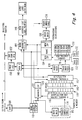
- FIGURE 4 is a block diagram of a system for updating the data in a system having a significant number of changes of data.
- In FIGURE 1, a conveyer 11 conveys a serial stream of letters L1-LN or other types of mail for reading by an optical character reader (OCR) 12.
OCR 12 reads the name, street, city, state and five digit zip code appearing on the face of the letters L1-LN. The name, street, city, state and five digit zip code read by theOCR 12 is supplied to system controller andmultiplexer 14.Multiplexer 14 has a plurality of parallel channel outputs 1A-D, 2A-D - 10A-D. These outputs are applied via multiple lines to CD-ROM controllers for reading data from anarray 15 of CD-ROM read systems. - For example, outputs 1A are applied to
controller 16A, outputs 1B are applied tocontroller 16B, and so forth. Outputs 2A-D ofmultiplexer 14 are respectively applied to a second set ofidentical controllers 17A-17D wherein outputs 2A are applied tocontroller 17A, outputs 2B are applied tocontroller 17B and so on. Theremaining outputs 3A-D - 10A-D are applied respectively to the remaining sets ofcontrollers controller sets 16A-16D and 17A-17D for receiving inputs from the system control andmultiplexer 14. -
Controller 16A operates anactuator 34,controller 16B operates anactuator 36,controller 16C operates an actuator 38 andcontroller 16D operates anactuator 40. Actuators 34-40 are mechanical devices for radially displacing respective laser read heads 44-50 secured thereto.Actuators ROM drive 42.Actuator 34 is radially aligned with actuator 38 on diametrical opposite sides of thedrive 42. Similarly,actuators actuators 34 and 38.Actuator 34 is coupled to aread head 44,actuator 36 is coupled to readhead 46, actuator 38 is coupled to readhead 48 andactuator 40 is coupled to readhead 50. Read heads 44-50 are identical and comprise a laser read mechanism as available in commercially available CD-ROM drive systems. Eachcontroller 16A-16D independently drives and controls the position of its respective corresponding read head 44-50 via the respective actuators 34-40. The use of plural read heads with independent actuators and controllers allows overlapping of periods of time to adjust the radial position of the heads as part of a seek operation. This permits the plural heads to be read consecutively without having to allow intervening time periods to adjust read head radial positions. - In similar fashion, a CD-ROM read head and actuator system is associated with each
controller 17A-17D and the remaining controller sets 18-32. The laser read drive subsystems are identical. - System control and
multiplexer 14 responds to the scan of the address on a given letter L1-LN and activates a selected one of the controllers to access a portion of a disc known a priori to contain the standard address and five+four zip code corresponding to the read letter. A CD-ROM disc is on each of the CD-ROM drives. Each disc is part of a data base containing the standard address including the city, state and five+four zip code. As known, the five-digit zip code refers to a destination locality whereas the additional four digit zip code narrows the destination to a given street or carrier route. The United States Postal System desires to bar code print the nine-digit zip code (five+four) onto each letter so that the letter may be automatically sorted by the bar code imprinted address by asorter 52.Sorter 52 may be of the first or second types as described above. To do this the controllers for each of the CD-ROM drive systems supply the additional four digit specific zip code in response to the reading of the normal five digit zip code appearing on each letter. - This requires the system to read the street address and five-digit zip code appearing on each letter. The system then extracts from a data base containing the standard street addresses and the nine-digit zip code for every such address range in the United States. System control and
multiplexer 14 generates from the read address and five-digit zip code an appropriate signal which identifies a particular controller of a particular disc drive system corresponding to that read data. That signal causes the read head of a given drive system to access the standard address and nine-digit zip code information from a given CD-ROM disc driven by that drive system. To perform this access the read head radial position is slewed to the approximate track location using a digital position encoder. The read head is then positioned to the desired track portion by counting tracks. Because conventional CD-ROMs have access time of about 1 to 2 seconds and because the postal system requires accessing of the data base at a rate of 12 items per second, normal CD-ROMs are too slow for this purpose. - By providing 10
drive systems - In a commercially available player, the head is moved radially to the approximate track location and the data is read to determine the actual location of the desired data. The read head is then radially displaced a smaller incremental distance and the data read again until the target data is located. This process, thus, is time consuming. By providing the four channels per disc, a 320ms access time can be allowed. Such performance is reasonable for the actuator and controllers as will be described below in more detail. If better performance is achieved by a specific actuator design, the number of channels can be reduced, still conforming to the principles of the embodiment described herein. Ten discs are illustrated in FIGURE 1 since it is believed that the nine-digit zip code defines a range of addresses which consists of about 29 million records requiring 3 gigabytes of data storage. Since a conventional CD-ROM disc contains about 0.5 gigabytes of data, it is believed that 10 discs are adequate to contain the 29 million records. Well understood techniques of data compression can be used to reduce the number of discs required.
- In response to the read address from
OCR 12 the system control andmultiplexer 14 determines which one of the systems 42-59 and which one of thecontrollers 16A-16D through 32 contains the desired address and generates an appropriate signal. That signal selects the specific read head and given drive system for accessing the data at that selected drive system. How the controllers operate and select the information and how the system controller derives the signal for selecting a given controller is described below in more detail in connection with FIGURE 3. - Once a signal is applied to a given controller and that controller read head accesses the data on its corresponding CD-ROM disc, the information is applied via
line 54 to system control andmultiplexer 14. The information accessed on a given CD-ROM disc is the standard street address range and corresponding nine-digit zip code. Once the information applied to themultiplexer 14,multiplexer 14 causesbar code printer 56, which may be a jet ink printer, to print the bar code representing the nine digit zip code on the individual letters such as letter L3. - In FIGURE 2
representative system 42 includes adisc drive 58 and a CD-ROM disc 60. Onecontroller 16A and its correspondingactuator 36 are shown in solid, the remaining controllers and actuators are represented by thebroken radial lines -
Disc 60 contains data which are recorded in a continuous inside out spiral track. As is known, CD-ROM discs contain data in a series of user data blocks of fixed size alternating with headers containing serial numbers and error detection codes. User data files may contain any number of data blocks. There are no sectors of fixed angular extent or discrete concentric tracks as is the common practice in magnetic disk recording. As a result, the length of a file depends on the amount of data in that file and the angular location of the beginning of the file may vary from track to track along the spiral. The header information as employed on the disc of the present data base is conventional. - The method of providing rapid access to data will now be described. The access time in a disc recording system has two components, conventionally named seek time and latency time. Seek time is that required for the read head to find a specific track, commonly by a generally radial movement (which may be in a straight line or arc). Latency time is that required for the disc to rotate to bring the desired data past the read head. In a CD-ROM, the latency time is determined by the rotation speed of the disc which in turn is a function of the data density of the track and the data bandwith of the processing circuits. For conventional CD ROMS, latency time may be over 200ms. Seek time must be reduced to tens of milliseconds to achieve the performance goal of 320ms access time. A CD-ROM player utilizes a pre-recorded plastic whose tracks are spaced about 1.6 micrometers apart. Because of thermal expansion and manufacturing variations, the exact radial position of a track is initially unknown to the system. In conventional CD-ROM players, specific tracks must be located by a method of successive approximation as described above. The present system provides a means for accessing the disc by each head in 320 milliseconds in on seek.
- Each disc of the data base, for
example disc 60, is marked withreference indicia Indicium 68 represents an angular reference mark by which the angular position of data from that reference mark is measured by the value of angle ϑ.Indicia 70 divide the disc into small angular increments to provide precise angular location of any point on the disc with reference to theindicia 68. Twosensors controller 16A for supplying information relative to the angular position of thereference indicium 68 and for providing information viaindicia 70 of the exact angular position of any point on thedisc 60. Eachcontroller 16A through 16D controllers 32 (FIGURE 1) include sensors such assensors -
Drive 58 rotatesdisc 60 at a constant angular speed. However, the data on the disc is recorded in its spiral format at a constant linear rate. Therefore, in reading the data along the spiral track as the distance r from the center of a disc changes in value, the frequency of the read data will also change. Since the data on the disc are binary in an encoded format, the interpretation of the signals from the optical read head will be performed by digital logic circuits and microprocessors which conventionally operate in a synchroneously organized fashion driven by a central clock oscillator. In a conventional CD-ROM player, the disc speed is adjusted as a function of playback head radius to give a constant playback data rate. Because thedisc 60 is driven at a constant angular rate, it would be impossible to read the data from the four read heads 44-50, which may be positioned at different radii, at a given constant data rate unless otherwise provided for. Means is provided as will be described below for reading the data from each of the tracks regardless the track radial distance r from the center of the disc at a constant data rate. In FIGURE 3, the radial line r is a measure of the distance from the axis 76 about whichdisc 60 rotates. Thedisc drive 58 ofsystem 42 includes aturntable 78 which receives thedisc 60 and further includes adrive motor 80 for rotating the table 78 at a constant angular rate. - Each of the
discs 60 as is known comprises static data impressed upon an optically reflective surface and coated with a transparent protective coating. The data comprise impressions formed in the reflective coating surface so that the transitions at the beginning and end of each depression form a binary signal representing the data. The binary one, for example may represent the transition from the bottom of the depression to the disc surface or vice versa whereas a binary zero may represent the bottom of the depression or the disc surface between depressions. These depressions are formed in a spiral track. The disc may be premastered and pressed in a conventional manner and the distributed to a wide number of local postal sorting stations located throughout the United States. - The data base comprises a set of ten discs. Each disc is associated with a
separate drive system 42. Encoded at the end of the data track of each disc is an indexing table. The indexing table comprises a hash index number and the r-ϑ coordinates of the file headers expressed in radial and angular dimensions. The table of coordinates is recorded last on the disc so that its presence does not disturb the locations of the files whose coordinates are calculated from the location of those files. The recording of a CD-ROM master is a precision process so that angular and radial location of any data block can be calculated in advance. A computer program prepares the database and the data block headers. From this data it is then possible to calculate an index map of the disc which is appended to the end of the files for each disc master tapes, so that the presence of the index does itself not disturb the order or location of the data files just organized. That information is then assigned unique numbers associated with the files. One example for deriving such unique numbers is a hashing technique. - In the hashing technique a number is extracted from the address including the street, city, state and five-digit zip code. The hash algorithm generates the index number. For example, the five digit zip code is concatenated with the address number and the initial letters of a street name. These represent a large digital number which is divided by 180,000 (the number of tracks on the ten discs). The remainder of such division comprises an index position on the spiral track relating to the header block serial number identifying a given file.
- Such an alogrithm, however, does not control the number of addresses which may share a given index number. This could create an overflow situation where the data is recorded in concentric rings as on a conventional magnetic disc file. Since the CD-ROM data is continuously recorded in a spiral, the file lengths in practice need not be uniform and there is no data overflow as the files are recorded contiguously, beginning-to-end. Thus, in the context of the illustrated system for each hash index number created, two coordinates are assigned to a location on a disc, the radius r and the header block angular location ϑ. The table at the end of the spiral track on each disc comprises the hash index number and its corresponding radius r and ϑ values.
- The system control and
multiplexer 14 includescomputer memory 82. Thememory 82 stores the hash index table that is read from a givendisc 60 when thedisc 60 is loaded onto thedrive system 42. One of the four read heads, e.g.,head 46, reads that table and transfers the information to thememory 82 ofmultiplexer 14 upon command bymultiplexer 14. -
Multiplexer 14 includes abuffer memory 84 for storing the name, street, city, state and five digit zip code read byOCR 12. This information is supplied tocomputer 86 which derives the hashing index number, as discussed above. Since in computer machine language all alpha characters are represented in ASCII character numbers, the letters and digits of the address form a serial set of digits which form can be interpreted as a number from which the hashing alogrithm of thecomputer 86 derives the hash index as previously explained. The name and address are supplied from thememory 84 to acomparator 88 for reasons to be explained later. A processor in multiplexer 14 (not shown) in response to the index number derived from the name and address read byOCR 12 from a letter L1-LN in the letter stream searches for the corresponding hashed index number in the table ofmemory 82. That index number corresponds to a given drive system 42-59 (FIGURE 1) and r-ϑ coordinates which locate the beginning of the file containing that name, address and nine-digit zip code in the disc on that drive system. - Having identified the drive system and r-ϑ coordinates of the file of interest, the information is sent via electronic signals on
lines 90 tocontroller 16A. It is assumed, for example, that the signal online 90′ is one which activatesdrive system 42 based on the correspondence of the hash index number to drive 42 in thememory 82. Of course, it should be understood that thelines 90 represent the lines to a single controller and that similar lines are fed to each of the other controllers corresponding to each read head in the system.Multiplexer 14 via a signal such as online 90′ selects that controller which is to receive the control signals and coordinates for driving the selected read head. - The signals on
lines 90 are applied toactuator control 92 ofsystem 42.Actuator control 92 may be a microprocessor for performing various functions to be described. One set of inputs to control 92 is the sense signals fromsensor control 92drives actuator 36.Actuator 36 is a commercially available read head drive for moving the readhead 46 back and forth in the radial direction relative todisc 60. Readhead 46 is commerically available and includes alaser 96 for reading the encoded data ondisc 60. Thelaser 96 is on asupport 98 which is moved in the radial directions byactuator 36. Coupled to support 98 is alinear position encoder 100. -
Linear position encoder 100 provides a digitally encoded signal representing the position of thelaser 96 along the radius r. The position of thelaser 96 is also measured by monitoring the track sense line from the disc readelectronics 102. This line transmits a plus or minus signal depending on whether the read head is inside or outside a specific track. When searching across the tracks, this signal varies cyclically as it passes over the tracks. By counting the cycles, the number of tracks passed can be determined by an algorithm inactuator control 92. Thelinear position encoder 100 serves to provide information to enable theactuator 36 to slew the readhead 46 to within several tracks ahead of the track containing the file of interest. The track count provides additional information to enable the actuator to position the readhead 46 at the track of interest. This permits the rapid accessing of the data base in a single seek within the 320 millisecond requirement described above.Linear position encoder 100 provides a signal toactuator control 92 giving the encoded position information of the radial location of the readhead 46. Theactuator control 92 uses this information fromencoder 100 to process the signals from themultiplexer 14 to precisely position thelaser 96 where desired in accordance with the given hash index number derived from a given letter. - Associated with the read
head 46 are the disc readelectronics 102 which read the information including sensing the tracks and other housekeeping track and data reading information. Thecontrol 92 generates a clock signal on line 104 for providing the appropriate data read rate forelectronics 102. The clock rate on line 104 differs in accordance with the radial distance r sensed by the readhead 46 and as interpreted by theelectronics 102. Included withincontrol 92 ismemory 106. -
Memory 106 contains a calibration table which includes the track radial distance r as derived from thememory 82 inmultiplexer 14, and which includes the actual distance r′ as measured byposition encoder 100 to the actual track represented by the corresponding hash index number. For each such assumed radius r and actual measured radius r′, a clock signal having a frequency f is assigned the r and r′ values. The clock frequency changes as the radial distance r of a given track changes relative to the axis 76 and is computed by the system for each actual r′ measured. The table inmemory 106 is created as the system is started up. The information on the tracks may include self-clocking codes for synchronizing the data read electronics. Theactuator control 92 includes a microprocessor (not shown) which periodically causes a read head to scan the tracks of itsdisc 60 to update track r′ information intomemory 106 updating the table. This update information may be multiplexed with the normal deployment of the read heads during data seek cycles. - The reason for updating the track location with the value r′ periodically and for providing the calibration table in
memory 106 is to compensate for manufacturing and environmentally caused track location errors. Temperature variations, manufacturing processes, and tolerances in pressing each disc are such that actual locations of the tracks on each disc may change from any predetermined value. Normally there will be local and global errors in the molding process, shrinkage after molding, and thermal expansion and aging effects in use which need to be compensated. The disc is thermoplastic material in which these track spacings are approximately 16 microns, which dimension can easily change due to the environmental conditions. Therefore, the radius r of any specific track, that is a turn of the spiral, cannot be precisely known in advance except by a periodic update calibration process. - The focus servo in a conventional CD-ROM system embodied in the
actuator control 92 operates independently of the data tracking. A drive signal onlead 90′ is applied toactuator controller 92 selectingsystem 42. The signals applied toactuator control 92 represent and r and ϑ coordinates for the hash index number derived from the street address on the letter L1 then being read byOCR 12. These coordinates, particularly the r coordinate, is used by thecalibration computer 106 to derive the r′ coordinate and determine the data clock frequency f for that r′. Theactuator control 92 in response to the r′ signal from the calibration computer then causes theencoder 100 to slew thelaser 96 of the readhead 46 into position. - The read
electronics 102 counts tracks supplying the track count to control 92.Control 92 in response to the track count moveslaser 96 to the position represented by the distance r′. At this point the disc read electronics counts tracks to position the readhead 46 at the target track. The address information in that file located on the targeted track is then read at the f data rate. Address information is supplied by the disc readelectronics 102 to terminal T, which applies that signal tocomparator 88. -
Comparator 88 includes a buffer for storing the street, city, state and zip code information that is read from the letter L1 and which corresponds to the file being read fromdisc 60. The city, state and the five-digit zip are compared with the city, state, five digit zip read from the file fromdisc 60. When there is a match, the comparator produces a signal and applies it to thebar code printer 56 for printing a bar code on letter L1, which in the meantime during operation of the system has moved along conveyor 11 into position overprinter 56. The bar code represents the nine-digit zip stored on thedisc 60 then being read.Bar code printer 56 is a ink jet printer which prints the bar code at the 12 letter per second rate.Data sorter 52 then reads the printed bar codes and sorts the letters by the nine-digit code. In the example given with respect to FIGURES 1-3, a zip+4 digit code was employed. However, the system is equally applicable to a zip+6 digit zip code which is a complete destination address for every entity in the United States. - In the description of FIGURES 2 and 3
system 42 was given by way of example in conjunction with the operation ofcontroller 16A. The operation of every other controller in the system associated with each of the ten disc drives is represented by the description given above. Further, the system control themultiplexer 14 can rapidly provide a read signal to each of thecontrollers 16A through 16D of a given disc drive operating those read heads. It should be understood that the letters are read sequentially and, therefore, there is a time lag between the operation of each of the read heads. Each head operation has a 320 millisecond duration, as described above. However, with the 320 millisecond delay for reading a particular track by a given head, the use of four heads per disc permits the four heads to operate in that 320 millisecond time frame and therefore, read that disc in 80 milliseconds. Any of the read heads at any of the disc drive systems may be read in any given time frame in accordance with the data read from letters L1-LN. Not shown in a synchronization system for synchronizing printing onto letter L3 byprinter 56. - While two sets of
indicia disc 60, oneindicium 68 for providing a angular reference for angle ϑ and the second set ofindicia 70 for providing precise angular positioning information about thedisc 60 relative toindicium 68 may be provided other means. For example, a single indicia mark such asindicium 68 may be provided without theindicia 70. The speed control system in a conventional CD-ROM player includes sufficient accurate speed control so that suitable timing can be derived from the speed setting system for providing precise angular locating information of data on the disc relative to indicia 68. Because the files may be of unknown length and differ from one another it does not matter where the file headers are positioned relative to thereference indicium 68. In this way the relatively slow operation of theactuator 36 is compensated for by the multiple actuators and read head systems associated with each disc drive system. - In the meantime, when a particular drive head is not in use or during a maintenance period of sufficient length,
control 92 automatically updates the calibration table inmemory 106. This is done by recomputing the values of r′ for each of the tracks on the disc. This recomputed r′ value is inserted inmemory 106 and the prior value erased. The values of the frequency f for the clock rate for reading the data are calculated by the calibration computer to providing accurate clock data for each value of r′. This calculation may be done, for example, using a lookup table stored in memory to specify a given clock rate for a range of values for r′ for all possible ranges on a given disc. - The term track as employed in the claims is intended to include a continuous spiral format or a plurality of concentric rings.
- One practical problem present in a normal postal system is the approximately 40 million changes of address annually, which average about 110,000 changes per day as discussed in the introductory portion. FIGURE 4 illustrates a system which can provide an on-line updated data base including the current changes of address. This system assumes that simple data compression techniques can be used to compress an eleven-digit zip code file to 5 gigabytes. This database is contained on ten discs each of which is accessed by the four heads described above in connection with FIGURES 1-3. Two sets 118 and 140 of such ten discs are employed in the system of FIGURE 4.
- Data from the
OCR 108 is stored inmemory 110 and includes the name, state, city, state and five digit zip code. The information is supplied to computer in memory 112 for extracting a hash index from the city, state and zip code in a manner similar to that described above in connection with FIGURE 3. The derived index is applied to a track index table stored in memory and derived from the CD-ROMs to initialize the system as also described above. The track index table in computer memory 112 provides the disc drive number and the r and ϑ coordinates on the particular disc. This information is applied on line 114 to a four-channel control multiplexer 116.Multiplexer 116 includes the functions of disc drive selection channel allocation and control of head actuators in a manner similar to that described with respect to the system control andmultiplexer 14 of FIGURE 3. CD-ROMplayer systems array 118 may have 10 players with four heads each. Each disc contains a portion of a data base comprising a five-digit zip+6 standard address file for all mail destinations in the United States. This data base comprises approximately 6 gigabytes of data which may be compressed. - The information read from the
array 118 is applied to comparator buffer 120. The comparator buffer contains the standard address and eleven-digit zip codes from the disc then being read byOCR 108. This information is used to locate the actual zip+6 code that is desired. In the buffer 120 the desired zip+6 code is placed in memory 122 of the buffer. That zip+6 code is the information that is read from the CD-ROM disc of one of the selectedplayer systems 118. The zip+6 code is applied to ahash indexing computer 124 which derives a index hash number from that zip code. This provides an index to table 126 in memory of names of people who have moved and changed addresses. -
Controller 128 receives the index information from table 126 and in a fashion similar to the operation ofmultiplexer 14 of FIGURE 3 selects that particular CD-ROM player system fromsystem array 130 which may be six player systems for seeking the name and zip+6 code from a CD-ROM disc containing a change of address file. Thearray 130 of discs contain current change of address files which is periodically updated. These discs contain only the names and zip+6 codes of those individuals or entities who have changed address. Each player ofsystem array 130 is operated by four heads as described above. The information on each of the discs ofsystem 130 include the old zip+6 code, the name of a person who has moved, and the new zip+6 code as the record format. In addition, there can be a field in each data file associated with that name and zip code indicating the postal patron's particular forwarding instructions. - These discs are prepared from change of address notices from postal patrons received at the different postal locations throughout the country. A set of
magnetic disc drives 132, for example, Winchester disc drives, contain the daily updates of change of addresses. Such daily change of address updates are provided to each local sorting station on a magnetic casette type cartridge. The cartridge is fed into a system which reads the information from the casette onto the magnetic discs ofdrives 132. - The postal service compiles on a daily basis the change of address notices nationwide and reads them onto the magnetic tape casette which are duplicated and mailed each day to the mail sorting centers. These tapes add to the track index table and to the contents of the magnetic discs so that these become extensions of a CD-ROM file on the
array 130 of discs. - When the magnetic discs are nearly full, a new set of CD-ROMs are issued which bring all changes up to date. Upon receipt of the new CD-ROMs, most of the data on the magnetic discs are purged. It is believed that not all of the data will be purged, as there will be a finite delay of several days between issuing the magnetic discs and the receipt of such updated discs. In this manner the file structure on the magnetic discs maintains the same simplicity as that on the CD-ROMs, so that the data may be accessed in a single seek. The magnetic disc drives and accessing heads are conventional and normally have relatively high access rates.
- The information from the CD-ROMs in the change of address file of
array 130 is selectively supplied via themultiplexer 128 to thecomparator buffer 134. Thecomparator buffer 134 contains the old zip code, the name of the individual and the new zip code. This provides a correspondence of the old zip code, the name of the individual who has moved, with the new zip code. Thebuffer 134 may also include memory storage including the forwarding instructions, if any, that an individual has requested and is recorded on the particular CD-ROMs of thesystem 130. - If there is a change of address for a given name, the hash/index procedure described above is used via
hash computer 136 and track index table 138 to derive an index to a second standard of addresses stored on array 140 of CD-ROM discs and corresponding discs players. The array of discs 140 are operated under the control ofmultiplexer 142 which is similar in operation and function tomultiplexer 116.Buffer 144 accumulates the new address and zip codes for change of address letters. The name and address are received frommultiplexer 142 and the new eleven-digit zip code is received frombuffer 134. This information is delivered to anexternal priner 146 which prepares printed labels. Those labels are the type which will be attached to the letters and have the name, address and new zip+6 codes on them so they can be ready by a mail delivery carrier. These letters are to be directed to a specific output channel in the letter sorter from which they will be taken to a printing station where the address labels can be attached. The order of the letters on the conveyer after being read byOCR 108 is preserved in this process. The labels may be applied by automatic or manual means. - A new zip code is supplied to
comparator 148 which compares the new zip code to the zip code in buffer 122, which letter code is the standard zip code found in the CD-ROM systems array 118. If the new zip code differs from the old zip code in buffer 122, a signal is sent to aprint list controller 150, which operates abar code printer 152 to print a bar code representing the new zip code. If the new zip code does not differ from the old zip code, indicating no change of address having been found, then theprint list controller 150 causes thebar code printer 152 to print the bar code representing the old zip code from buffer 122. The bar code is imprinted on the letters in the letter stream which are then later automatically sorted in the process. The sorted letters are then stored in sequence as printed byprinter 152 for receiving the labels for those which have a new address. The new address label is then applied as set forth above. Thus the bar code fromprinter 152 indicates on the information encoded in the bar code that a particular letter is in need of a change of address label or that its address is unchanged. Because themagnetic discs 132 are updated daily, change of addresses for all destinations are included in the zip+6 code on a current, practical basis. The CD-ROM discs are easily manufactured and distributed, as needed, to the different letter sorting locations throughout the nation.
Claims (24)
disc drive means for receiving and rotatably driving a disc;
a plurality of optical disc read means associated with said disc drive means for reading said data elements from the disc then being driven by that drive means at respective ones of angular spaced locations, each said read means including a respective actuator means responsive to an applied control signal representing a given file position for independently reading the data elements from the file corresponding to that given file position; and
control means for generating said control signal and for selectively applying said control signal to a currently selected one of said read means.
disc drive means for receiving and rotating said disc about an axis;
a plurality of laser disc read means coupled to said drive means at angular spaced positions about said axis, each read means including means for reading said data from anywhere on said track, each read means including means for reading data from said disc independent of the reading of data by the remaining read means, each read means including a read head and read head positioning means, said read head positioning means including means responsive to a read head positioning signal applied as an input thereto for aligning the head relative to a given file track; and
control means responsive to an applied input signal for generating said read head positioning signal and for applying said positioning signal to said read means.
a plurality of CD-ROM disc drive means, each for receiving and rotating a CD ROM disc having a spirally encoded track containing a plurality of contiguous files, each file comprising a data block containing synchronization data, file address data, zip code address plus x for a plurality of zip code addresses, and error detection and error correction data;
means for reading the five digit zip code address on said object and for deriving a unique number for each different read address;
means for correlating each said derived number to a given disc containing that read zip code and to a given angular position on that given disc from a reference angular position and to a given radial distance from the center of that given disc to the file containing that zip code address and for generating an output signal representing said correlated angular position, radial distance and given disc in response to the reading of said address on said object; and
a plurality of disc read means coupled to each said drive means responsive to said output signal applied thereto for reading that file located at that angular position and radial distance on that given disc.
CD-ROM disc drive means for driving a received disc at a constant angular velocity resulting in different playback rates for different radius portions of the track;
a plurality of read head means coupled to said drive means for independently accessing and reading data at a plurality of disc locations from anywhere on a given disc at substantially the same constant data rate regardless the difference in actual data rats occurring on the different track portions being read; and
control means for selecting and operating the selected read head means.
means for reading the name and address on the letter;
meand including first CD-ROMS for deriving and generating a standard eleven-digit-zip code from said read name and address.
means including second CD-ROMS for determining if a given read name and address has a corresponding change of address and for storing in memory the new eleven-digit zip code for such change of address;
means for printing the stored new zip code, if any, on said read letter' or, if not new, the old zip code, and
means for printing an address label containing the new, changed complete address, if any, for said letter in response to said determining.
drive means to rotate the data carrier at a constant angular velocity, resulting in different data linear veolocities at different data carrier radii; and
a plurality of read head means for independently accessing and reading data each from a plurality of different data carrier radii, the read head means having to vary the speed of their internal data reading operations in accordance with variation in the radius at which data is read so as to correspond with the data linear velocity at the current reading radius.
Applications Claiming Priority (2)
| Application Number | Priority Date | Filing Date | Title |
|---|---|---|---|
| US80123 | 1979-09-27 | ||
| US07/080,123 US4871903A (en) | 1987-07-31 | 1987-07-31 | Apparatus for rapidly accessing a large data base employing an optical disc reading system with multiple heads and track position compensation means |
Publications (3)
| Publication Number | Publication Date |
|---|---|
| EP0301909A2 true EP0301909A2 (en) | 1989-02-01 |
| EP0301909A3 EP0301909A3 (en) | 1990-09-26 |
| EP0301909B1 EP0301909B1 (en) | 1994-09-28 |
Family
ID=22155396
Family Applications (1)
| Application Number | Title | Priority Date | Filing Date |
|---|---|---|---|
| EP88307061A Expired - Lifetime EP0301909B1 (en) | 1987-07-31 | 1988-07-29 | Apparatus for rapidly accessing a large data base |
Country Status (4)
| Country | Link |
|---|---|
| US (1) | US4871903A (en) |
| EP (1) | EP0301909B1 (en) |
| JP (1) | JPH01100783A (en) |
| DE (1) | DE3851674T2 (en) |
Cited By (4)
| Publication number | Priority date | Publication date | Assignee | Title |
|---|---|---|---|---|
| EP0420209A2 (en) * | 1989-09-29 | 1991-04-03 | Kabushiki Kaisha Toshiba | A recording/reproducing apparatus |
| EP0550080A1 (en) * | 1991-10-18 | 1993-07-07 | Wouterus Hendrikus Maria Dekkers | Method and device for the automatic processing of data recorded on a tachograph chart |
| US6954729B2 (en) * | 2000-01-27 | 2005-10-11 | Bowe Bell & Howell Postal Systems Company | Address learning system and method for using same |
| US20120030473A1 (en) * | 2005-07-15 | 2012-02-02 | Microsoft Corporation | Unique block header patterns for media verification |
Families Citing this family (40)
| Publication number | Priority date | Publication date | Assignee | Title |
|---|---|---|---|---|
| US4992649A (en) * | 1988-09-30 | 1991-02-12 | United States Postal Service | Remote video scanning automated sorting system |
| US4972396A (en) * | 1988-10-24 | 1990-11-20 | Honeywell Inc. | Multiple independently positionable recording-reading head disk system |
| US5568454A (en) * | 1989-03-09 | 1996-10-22 | Tosoh Corporation | Apparatus and method for detecting a defect on a magneto-optical disk |
| US5291002A (en) * | 1989-06-28 | 1994-03-01 | Z Mark International Inc. | System for generating machine readable codes to facilitate routing of correspondence using automatic mail sorting apparatus |
| US5274463A (en) * | 1990-03-27 | 1993-12-28 | Sony Corporation | Still picture storing and sequencing apparatus |
| US5431288A (en) * | 1991-08-28 | 1995-07-11 | Nec Corporation | Mail sorting apparatus |
| US5434678A (en) * | 1993-01-11 | 1995-07-18 | Abecassis; Max | Seamless transmission of non-sequential video segments |
| US5420403A (en) * | 1992-05-26 | 1995-05-30 | Canada Post Corporation | Mail encoding and processing system |
| DE69331741T2 (en) * | 1993-10-04 | 2002-10-02 | Siemens Ag | Method and device for quick access to data units of a sorted list and database carrier for this method and / or this device |
| US5542087A (en) * | 1993-10-15 | 1996-07-30 | Hewlett-Packard Company | Linear hashing for distributed records |
| US5523995A (en) * | 1994-04-01 | 1996-06-04 | Lichtenberg; Heinz D. | Optical information read/write system with a spread plane beam |
| US5502696A (en) * | 1994-09-23 | 1996-03-26 | Cirrus Logic, Inc. | CD-ROM subcode R-W channel de-interleaving and de-scrambling method and apparatus |
| US5734731A (en) * | 1994-11-29 | 1998-03-31 | Marx; Elliot S. | Real time audio mixer |
| JP4548862B2 (en) * | 1995-04-28 | 2010-09-22 | コーニンクレッカ フィリップス エレクトロニクス エヌ ヴィ | System for storing and reproducing information |
| DE69610861T2 (en) * | 1995-10-09 | 2001-03-15 | Matsushita Electric Ind Co Ltd | Optical disc and optical playback device |
| US5872747A (en) * | 1997-01-16 | 1999-02-16 | Jbs Enterprises, Inc. | Apparatus and method for scheduled playing of compact disc audio tracks |
| US5923891A (en) * | 1997-03-14 | 1999-07-13 | Diva Systems Corporation | System for minimizing disk access using the computer maximum seek time between two furthest apart addresses to control the wait period of the processing element |
| US7296004B1 (en) * | 1997-12-19 | 2007-11-13 | Checkfree Corporation | Electronic bill payment system with merchant identification |
| US7711690B1 (en) | 1998-01-21 | 2010-05-04 | Checkfree Corporation | Dual source remittance processing |
| US6268228B1 (en) * | 1999-01-27 | 2001-07-31 | International Business Machines Corporation | Electrical mask identification of memory modules |
| AU2001285161A1 (en) * | 2000-08-21 | 2002-03-04 | United States Postal Services | Delivery point validation system |
| US7975021B2 (en) | 2000-10-23 | 2011-07-05 | Clearplay, Inc. | Method and user interface for downloading audio and video content filters to a media player |
| US6898799B1 (en) | 2000-10-23 | 2005-05-24 | Clearplay, Inc. | Multimedia content navigation and playback |
| US6889383B1 (en) | 2000-10-23 | 2005-05-03 | Clearplay, Inc. | Delivery of navigation data for playback of audio and video content |
| AU2002230732A1 (en) * | 2000-12-15 | 2002-06-24 | United States Postal Service | Just-in-time sort plan creation |
| WO2002077874A1 (en) * | 2001-03-22 | 2002-10-03 | United States Postal Service | System and method for standardizing a mailing address |
| AU2002244330A1 (en) * | 2001-03-23 | 2002-10-08 | United States Postal Service | Residential delivery indicator |
| JP2003199045A (en) * | 2001-12-26 | 2003-07-11 | Victor Co Of Japan Ltd | Information-recording-signal generating method and apparatus, information-signal reproducing method and apparatus, information-signal transmitting method, apparatus and program, and information-signal recording medium |
| US7587408B2 (en) * | 2002-03-21 | 2009-09-08 | United States Postal Service | Method and system for storing and retrieving data using hash-accessed multiple data stores |
| US7664731B2 (en) * | 2002-03-21 | 2010-02-16 | United States Postal Service | Method and system for storing and retrieving data using hash-accessed multiple data stores |
| US7159119B2 (en) * | 2002-09-06 | 2007-01-02 | United States Postal Service | Method and system for efficiently retrieving secured data by securely pre-processing provided access information |
| AU2004304818A1 (en) | 2003-10-22 | 2005-07-07 | Clearplay, Inc. | Apparatus and method for blocking audio/visual programming and for muting audio |
| US8117282B2 (en) | 2004-10-20 | 2012-02-14 | Clearplay, Inc. | Media player configured to receive playback filters from alternative storage mediums |
| US8279545B2 (en) | 2004-12-03 | 2012-10-02 | The Invention Science Fund I, Llc | High bandwidth data transfer to and from rotating data storage devices |
| US7230784B2 (en) * | 2004-12-03 | 2007-06-12 | Searete, Llc | High bandwidth data transfer to and from rotating data storage devices |
| US7849048B2 (en) * | 2005-07-05 | 2010-12-07 | Clarabridge, Inc. | System and method of making unstructured data available to structured data analysis tools |
| US7849049B2 (en) * | 2005-07-05 | 2010-12-07 | Clarabridge, Inc. | Schema and ETL tools for structured and unstructured data |
| WO2007010587A1 (en) | 2005-07-15 | 2007-01-25 | Mitsubishi Denki Kabushiki Kaisha | Recording medium reproducing device, recording medium reproducing method, and portable recording medium |
| US10372741B2 (en) | 2012-03-02 | 2019-08-06 | Clarabridge, Inc. | Apparatus for automatic theme detection from unstructured data |
| US10664170B2 (en) * | 2016-12-14 | 2020-05-26 | Microsoft Technology Licensing, Llc | Partial storage of large files in distinct storage systems |
Citations (6)
| Publication number | Priority date | Publication date | Assignee | Title |
|---|---|---|---|---|
| US3829610A (en) * | 1971-05-26 | 1974-08-13 | Agfa Gevaert Ag | Apparatus for simultaneous reproduction of visible and audible information |
| US4142209A (en) * | 1976-03-19 | 1979-02-27 | Rca Corporation | Disc track servo system |
| WO1985001382A1 (en) * | 1983-09-19 | 1985-03-28 | Storage Technology Partners Ii | Optically storing digital data |
| EP0177737A2 (en) * | 1984-08-28 | 1986-04-16 | Fuji Photo Film Co., Ltd. | Optical memory disk and track access therefor |
| WO1986003325A1 (en) * | 1984-11-20 | 1986-06-05 | Resolution Research, Incorporated | Interactive multi-user laser disc system |
| EP0228646A2 (en) * | 1985-12-20 | 1987-07-15 | Hitachi, Ltd. | A signal processing apparatus for disc memory devices |
Family Cites Families (17)
| Publication number | Priority date | Publication date | Assignee | Title |
|---|---|---|---|---|
| US3774172A (en) * | 1972-03-23 | 1973-11-20 | D Silverman | Random access multiple disc optical information storage system |
| US4270154A (en) * | 1978-03-01 | 1981-05-26 | Crawford John E | Head selection technique |
| US4423448A (en) * | 1979-12-26 | 1983-12-27 | Burroughs Corporation | Multi-path to data facility for disk drive transducer arms |
| JPS57208639A (en) * | 1981-06-18 | 1982-12-21 | Toshiba Corp | Recording method of disk |
| US4414590A (en) * | 1981-06-29 | 1983-11-08 | Storage Technology Corporation | Media interchange switch for magnetic disk drives |
| JPS5855076A (en) * | 1981-09-29 | 1983-04-01 | 株式会社東芝 | Apparatus for separating papers |
| US4481412A (en) * | 1982-06-21 | 1984-11-06 | Fields Craig I | Interactive videodisc training system with bar code access |
| US4529871A (en) * | 1982-09-29 | 1985-07-16 | Loblaw Companies Limited | Price marking system |
| JPS59186138A (en) * | 1983-04-06 | 1984-10-22 | Konishiroku Photo Ind Co Ltd | Optical information recording and reproducing device |
| JPS60109087A (en) * | 1983-11-17 | 1985-06-14 | Nec Corp | Disk storage device |
| JPS6093172U (en) * | 1983-11-30 | 1985-06-25 | パイオニア株式会社 | Recorded information reproducing device |
| JPS60137476A (en) * | 1983-12-26 | 1985-07-22 | 株式会社東芝 | Sorter for mail |
| JPS60177404A (en) * | 1984-02-23 | 1985-09-11 | Toshiba Corp | Disk device |
| JPS61131236A (en) * | 1984-11-29 | 1986-06-18 | Matsushita Electric Ind Co Ltd | Optical information recording and reproducing system |
| KR940002001B1 (en) * | 1985-03-22 | 1994-03-12 | 가부시끼가이샤 히다찌세이사꾸쇼 | Access method and the information checking device |
| US4725718A (en) * | 1985-08-06 | 1988-02-16 | Pitney Bowes Inc. | Postage and mailing information applying system |
| JPS6292293A (en) * | 1985-10-18 | 1987-04-27 | Nec Corp | Responsing device |
-
1987
- 1987-07-31 US US07/080,123 patent/US4871903A/en not_active Expired - Lifetime
-
1988
- 1988-07-29 EP EP88307061A patent/EP0301909B1/en not_active Expired - Lifetime
- 1988-07-29 DE DE3851674T patent/DE3851674T2/en not_active Expired - Fee Related
- 1988-07-29 JP JP63188514A patent/JPH01100783A/en active Pending
Patent Citations (6)
| Publication number | Priority date | Publication date | Assignee | Title |
|---|---|---|---|---|
| US3829610A (en) * | 1971-05-26 | 1974-08-13 | Agfa Gevaert Ag | Apparatus for simultaneous reproduction of visible and audible information |
| US4142209A (en) * | 1976-03-19 | 1979-02-27 | Rca Corporation | Disc track servo system |
| WO1985001382A1 (en) * | 1983-09-19 | 1985-03-28 | Storage Technology Partners Ii | Optically storing digital data |
| EP0177737A2 (en) * | 1984-08-28 | 1986-04-16 | Fuji Photo Film Co., Ltd. | Optical memory disk and track access therefor |
| WO1986003325A1 (en) * | 1984-11-20 | 1986-06-05 | Resolution Research, Incorporated | Interactive multi-user laser disc system |
| EP0228646A2 (en) * | 1985-12-20 | 1987-07-15 | Hitachi, Ltd. | A signal processing apparatus for disc memory devices |
Non-Patent Citations (2)
| Title |
|---|
| IEEE TRANSACTIONS ON CONSUMER ELECTRONICS. November 1976, NEW YORK US pages 327 - 337; George C. Kenney: "Special Purpose Applications of the Optical Videodisc System" * |
| SMPTE JOURNAL. vol. 86, February 1977, US pages 80 - 83; Michel Mathieu: "A Random Access Adapted for the Optical Videodisc:Its impact on Information retrieval" * |
Cited By (7)
| Publication number | Priority date | Publication date | Assignee | Title |
|---|---|---|---|---|
| EP0420209A2 (en) * | 1989-09-29 | 1991-04-03 | Kabushiki Kaisha Toshiba | A recording/reproducing apparatus |
| EP0420209A3 (en) * | 1989-09-29 | 1991-12-27 | Kabushiki Kaisha Toshiba | A recording/reproducing apparatus |
| US5155722A (en) * | 1989-09-29 | 1992-10-13 | Kabushiki Kaisha Toshiba | Recording/reproducing apparatus |
| EP0550080A1 (en) * | 1991-10-18 | 1993-07-07 | Wouterus Hendrikus Maria Dekkers | Method and device for the automatic processing of data recorded on a tachograph chart |
| US6954729B2 (en) * | 2000-01-27 | 2005-10-11 | Bowe Bell & Howell Postal Systems Company | Address learning system and method for using same |
| US20120030473A1 (en) * | 2005-07-15 | 2012-02-02 | Microsoft Corporation | Unique block header patterns for media verification |
| US8555076B2 (en) * | 2005-07-15 | 2013-10-08 | Microsoft Corporation | Unique block header patterns for media verification |
Also Published As
| Publication number | Publication date |
|---|---|
| EP0301909A3 (en) | 1990-09-26 |
| US4871903A (en) | 1989-10-03 |
| EP0301909B1 (en) | 1994-09-28 |
| DE3851674T2 (en) | 1995-05-18 |
| JPH01100783A (en) | 1989-04-19 |
| DE3851674D1 (en) | 1994-11-03 |
Similar Documents
| Publication | Publication Date | Title |
|---|---|---|
| US4871903A (en) | Apparatus for rapidly accessing a large data base employing an optical disc reading system with multiple heads and track position compensation means | |
| CN1023922C (en) | Sectored servo independent of data architecture | |
| US3662363A (en) | Memory system using phonograph-type disc | |
| US5418764A (en) | Recording device, a record carrier having preformatted address codes and auxiliary codes providing control data for use by the recording device, and an information recording system including both the recording device and the record carrier | |
| CN1020977C (en) | Recording system as well as record carrier and recording appratus for use in system | |
| CA1298405C (en) | Optical recording method for data cards | |
| US4634850A (en) | Quad density optical data system | |
| CN1024603C (en) | Information recording system, and recording device and record carrier for use in such an information recording system | |
| US5757568A (en) | System and method for encoding a servo address | |
| US5202876A (en) | Optical disc recording-reproducing apparatus in which sector substitution of defective sectors is performed | |
| EP0357614A4 (en) | Read-only optical card and system. | |
| EP0613136A3 (en) | Data recording and reproducing method | |
| RU96119948A (en) | SYSTEM AND METHOD FOR CODING SERVOADDRESS | |
| WO1985001818A1 (en) | Quad density optical data system | |
| US5107377A (en) | Method and apparatus for digital storage and retrieval of data | |
| US6736475B2 (en) | Method for providing angular position information for a radial printing system | |
| JPH08509315A (en) | Method and apparatus for storing data and auxiliary information | |
| US4176996A (en) | Automatic positioning system for a carriage in a storage and retrieval system | |
| WO1982004489A1 (en) | Information storage and retrieval | |
| US5794238A (en) | Method and apparatus for accessing a large scale data array | |
| CN1157049A (en) | System for storying and reproducing information | |
| CN1096072C (en) | Apparatus for controlling rotational servo by using frequency pulse signal generator | |
| CN1123884C (en) | Magnetic disk device with lower probability of read error caused by surface seratch of magnetic disk | |
| US4888753A (en) | Information recording medium capable of accurately detecting the recording and reproduction starting positions and an information recording-reproducing method and apparatus therefor | |
| US3662339A (en) | Listing verification system |
Legal Events
| Date | Code | Title | Description |
|---|---|---|---|
| PUAI | Public reference made under article 153(3) epc to a published international application that has entered the european phase |
Free format text: ORIGINAL CODE: 0009012 |
|
| AK | Designated contracting states |
Kind code of ref document: A2 Designated state(s): DE FR NL |
|
| PUAL | Search report despatched |
Free format text: ORIGINAL CODE: 0009013 |
|
| AK | Designated contracting states |
Kind code of ref document: A3 Designated state(s): DE FR NL |
|
| RHK1 | Main classification (correction) |
Ipc: G11B 7/14 |
|
| 17P | Request for examination filed |
Effective date: 19901210 |
|
| 17Q | First examination report despatched |
Effective date: 19920416 |
|
| GRAA | (expected) grant |
Free format text: ORIGINAL CODE: 0009210 |
|
| AK | Designated contracting states |
Kind code of ref document: B1 Designated state(s): DE FR NL |
|
| ET | Fr: translation filed | ||
| REF | Corresponds to: |
Ref document number: 3851674 Country of ref document: DE Date of ref document: 19941103 |
|
| PLBE | No opposition filed within time limit |
Free format text: ORIGINAL CODE: 0009261 |
|
| STAA | Information on the status of an ep patent application or granted ep patent |
Free format text: STATUS: NO OPPOSITION FILED WITHIN TIME LIMIT |
|
| 26N | No opposition filed | ||
| PG25 | Lapsed in a contracting state [announced via postgrant information from national office to epo] |
Ref country code: NL Effective date: 19960201 |
|
| NLV4 | Nl: lapsed or anulled due to non-payment of the annual fee |
Effective date: 19960201 |
|
| PG25 | Lapsed in a contracting state [announced via postgrant information from national office to epo] |
Ref country code: DE Effective date: 19960402 |
|
| PG25 | Lapsed in a contracting state [announced via postgrant information from national office to epo] |
Ref country code: FR Effective date: 19960430 |
|
| REG | Reference to a national code |
Ref country code: FR Ref legal event code: ST |
|
| REG | Reference to a national code |
Ref country code: FR Ref legal event code: ST |
|
| REG | Reference to a national code |
Ref country code: FR Ref legal event code: ST |