EP0306545A1 - Compound multi-function gym benches - Google Patents
Compound multi-function gym benches Download PDFInfo
- Publication number
- EP0306545A1 EP0306545A1 EP87113184A EP87113184A EP0306545A1 EP 0306545 A1 EP0306545 A1 EP 0306545A1 EP 87113184 A EP87113184 A EP 87113184A EP 87113184 A EP87113184 A EP 87113184A EP 0306545 A1 EP0306545 A1 EP 0306545A1
- Authority
- EP
- European Patent Office
- Prior art keywords
- rod
- post
- compound multi
- weight
- seat
- Prior art date
- Legal status (The legal status is an assumption and is not a legal conclusion. Google has not performed a legal analysis and makes no representation as to the accuracy of the status listed.)
- Granted
Links
- 150000001875 compounds Chemical class 0.000 title claims abstract description 21
- 230000003028 elevating effect Effects 0.000 claims description 12
- 210000005069 ears Anatomy 0.000 claims description 5
- 230000002035 prolonged effect Effects 0.000 claims description 3
- 238000005452 bending Methods 0.000 claims description 2
- 230000000087 stabilizing effect Effects 0.000 claims 1
- 238000010276 construction Methods 0.000 description 1
- 238000004519 manufacturing process Methods 0.000 description 1
- 210000003205 muscle Anatomy 0.000 description 1
Images


Classifications
-
- A—HUMAN NECESSITIES
- A63—SPORTS; GAMES; AMUSEMENTS
- A63B—APPARATUS FOR PHYSICAL TRAINING, GYMNASTICS, SWIMMING, CLIMBING, OR FENCING; BALL GAMES; TRAINING EQUIPMENT
- A63B22/00—Exercising apparatus specially adapted for conditioning the cardio-vascular system, for training agility or co-ordination of movements
- A63B22/06—Exercising apparatus specially adapted for conditioning the cardio-vascular system, for training agility or co-ordination of movements with support elements performing a rotating cycling movement, i.e. a closed path movement
- A63B22/0605—Exercising apparatus specially adapted for conditioning the cardio-vascular system, for training agility or co-ordination of movements with support elements performing a rotating cycling movement, i.e. a closed path movement performing a circular movement, e.g. ergometers
-
- A—HUMAN NECESSITIES
- A63—SPORTS; GAMES; AMUSEMENTS
- A63B—APPARATUS FOR PHYSICAL TRAINING, GYMNASTICS, SWIMMING, CLIMBING, OR FENCING; BALL GAMES; TRAINING EQUIPMENT
- A63B21/00—Exercising apparatus for developing or strengthening the muscles or joints of the body by working against a counterforce, with or without measuring devices
- A63B21/06—User-manipulated weights
- A63B21/062—User-manipulated weights including guide for vertical or non-vertical weights or array of weights to move against gravity forces
- A63B21/0626—User-manipulated weights including guide for vertical or non-vertical weights or array of weights to move against gravity forces with substantially vertical guiding means
-
- A—HUMAN NECESSITIES
- A63—SPORTS; GAMES; AMUSEMENTS
- A63B—APPARATUS FOR PHYSICAL TRAINING, GYMNASTICS, SWIMMING, CLIMBING, OR FENCING; BALL GAMES; TRAINING EQUIPMENT
- A63B21/00—Exercising apparatus for developing or strengthening the muscles or joints of the body by working against a counterforce, with or without measuring devices
- A63B21/15—Arrangements for force transmissions
- A63B21/151—Using flexible elements for reciprocating movements, e.g. ropes or chains
- A63B21/154—Using flexible elements for reciprocating movements, e.g. ropes or chains using special pulley-assemblies
-
- A—HUMAN NECESSITIES
- A63—SPORTS; GAMES; AMUSEMENTS
- A63B—APPARATUS FOR PHYSICAL TRAINING, GYMNASTICS, SWIMMING, CLIMBING, OR FENCING; BALL GAMES; TRAINING EQUIPMENT
- A63B21/00—Exercising apparatus for developing or strengthening the muscles or joints of the body by working against a counterforce, with or without measuring devices
- A63B21/40—Interfaces with the user related to strength training; Details thereof
- A63B21/4027—Specific exercise interfaces
- A63B21/4029—Benches specifically adapted for exercising
- A63B21/4031—Benches specifically adapted for exercising with parts of the bench moving against a resistance during exercise
-
- A—HUMAN NECESSITIES
- A63—SPORTS; GAMES; AMUSEMENTS
- A63B—APPARATUS FOR PHYSICAL TRAINING, GYMNASTICS, SWIMMING, CLIMBING, OR FENCING; BALL GAMES; TRAINING EQUIPMENT
- A63B22/00—Exercising apparatus specially adapted for conditioning the cardio-vascular system, for training agility or co-ordination of movements
- A63B22/0002—Exercising apparatus specially adapted for conditioning the cardio-vascular system, for training agility or co-ordination of movements involving an exercising of arms
- A63B22/0005—Exercising apparatus specially adapted for conditioning the cardio-vascular system, for training agility or co-ordination of movements involving an exercising of arms with particular movement of the arms provided by handles moving otherwise than pivoting about a horizontal axis parallel to the body-symmetrical-plane
-
- A—HUMAN NECESSITIES
- A63—SPORTS; GAMES; AMUSEMENTS
- A63B—APPARATUS FOR PHYSICAL TRAINING, GYMNASTICS, SWIMMING, CLIMBING, OR FENCING; BALL GAMES; TRAINING EQUIPMENT
- A63B22/00—Exercising apparatus specially adapted for conditioning the cardio-vascular system, for training agility or co-ordination of movements
- A63B22/20—Exercising apparatus specially adapted for conditioning the cardio-vascular system, for training agility or co-ordination of movements using rollers, wheels, castors or the like, e.g. gliding means, to be moved over the floor or other surface, e.g. guide tracks, during exercising
- A63B22/201—Exercising apparatus specially adapted for conditioning the cardio-vascular system, for training agility or co-ordination of movements using rollers, wheels, castors or the like, e.g. gliding means, to be moved over the floor or other surface, e.g. guide tracks, during exercising for moving a support element in reciprocating translation, i.e. for sliding back and forth on a guide track
- A63B22/205—Exercising apparatus specially adapted for conditioning the cardio-vascular system, for training agility or co-ordination of movements using rollers, wheels, castors or the like, e.g. gliding means, to be moved over the floor or other surface, e.g. guide tracks, during exercising for moving a support element in reciprocating translation, i.e. for sliding back and forth on a guide track in a substantially vertical plane, e.g. for exercising against gravity
-
- A—HUMAN NECESSITIES
- A63—SPORTS; GAMES; AMUSEMENTS
- A63B—APPARATUS FOR PHYSICAL TRAINING, GYMNASTICS, SWIMMING, CLIMBING, OR FENCING; BALL GAMES; TRAINING EQUIPMENT
- A63B23/00—Exercising apparatus specially adapted for particular parts of the body
- A63B23/035—Exercising apparatus specially adapted for particular parts of the body for limbs, i.e. upper or lower limbs, e.g. simultaneously
- A63B23/12—Exercising apparatus specially adapted for particular parts of the body for limbs, i.e. upper or lower limbs, e.g. simultaneously for upper limbs or related muscles, e.g. chest, upper back or shoulder muscles
- A63B23/1245—Primarily by articulating the shoulder joint
- A63B23/1263—Rotation about an axis passing through both shoulders, e.g. cross-country skiing-type arm movements
-
- A—HUMAN NECESSITIES
- A63—SPORTS; GAMES; AMUSEMENTS
- A63B—APPARATUS FOR PHYSICAL TRAINING, GYMNASTICS, SWIMMING, CLIMBING, OR FENCING; BALL GAMES; TRAINING EQUIPMENT
- A63B21/00—Exercising apparatus for developing or strengthening the muscles or joints of the body by working against a counterforce, with or without measuring devices
- A63B21/22—Resisting devices with rotary bodies
- A63B21/225—Resisting devices with rotary bodies with flywheels
-
- A—HUMAN NECESSITIES
- A63—SPORTS; GAMES; AMUSEMENTS
- A63B—APPARATUS FOR PHYSICAL TRAINING, GYMNASTICS, SWIMMING, CLIMBING, OR FENCING; BALL GAMES; TRAINING EQUIPMENT
- A63B2225/00—Miscellaneous features of sport apparatus, devices or equipment
- A63B2225/09—Adjustable dimensions
-
- A—HUMAN NECESSITIES
- A63—SPORTS; GAMES; AMUSEMENTS
- A63B—APPARATUS FOR PHYSICAL TRAINING, GYMNASTICS, SWIMMING, CLIMBING, OR FENCING; BALL GAMES; TRAINING EQUIPMENT
- A63B2225/00—Miscellaneous features of sport apparatus, devices or equipment
- A63B2225/10—Multi-station exercising machines
-
- A—HUMAN NECESSITIES
- A63—SPORTS; GAMES; AMUSEMENTS
- A63B—APPARATUS FOR PHYSICAL TRAINING, GYMNASTICS, SWIMMING, CLIMBING, OR FENCING; BALL GAMES; TRAINING EQUIPMENT
- A63B23/00—Exercising apparatus specially adapted for particular parts of the body
- A63B23/035—Exercising apparatus specially adapted for particular parts of the body for limbs, i.e. upper or lower limbs, e.g. simultaneously
- A63B23/04—Exercising apparatus specially adapted for particular parts of the body for limbs, i.e. upper or lower limbs, e.g. simultaneously for lower limbs
- A63B23/0494—Exercising apparatus specially adapted for particular parts of the body for limbs, i.e. upper or lower limbs, e.g. simultaneously for lower limbs primarily by articulating the knee joints
Landscapes
- Health & Medical Sciences (AREA)
- General Health & Medical Sciences (AREA)
- Physical Education & Sports Medicine (AREA)
- Orthopedic Medicine & Surgery (AREA)
- Life Sciences & Earth Sciences (AREA)
- Biophysics (AREA)
- Cardiology (AREA)
- Vascular Medicine (AREA)
- Motorcycle And Bicycle Frame (AREA)
- Special Chairs (AREA)
Abstract

Description
- Machines or instruments for body or muscle building are generally divided into two kinds, one for a training center and the other for homes. The former are rather complicated equipped with various functions in one machine for many people to use; the latter are mostly constructed for only one function in one machine or instrument to cope with the living environment.
- A person has to get various kinds of machine or instrument in order to make a balanced training for every part of his body. Then these machines or instruments may occupy not a little room or space in the house, and cost quite a large amount of expenditure as well. So it may be a good idea that personal gym machines or instruments would have multi-functions, compact construction, and little space if they could be broadly used by private persons at home.
- Therefore, the inventor, having engaged in manufacturing gym machines many years, has worked out this compound multi-function gym bench, which is usable not only at home but at a training center, too. This compact machine can replace common large or single-function ones. By changing the various parts in this bench, a person can use it for bike pedaling exercise, weight lifting or rope pulling either by hand or foot whether in a sitting, lying or standing position.
-
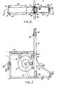
- Figure 1 is a side view of the seat frame combined with the hollow post in this invention.
- Figure 2 is a top side view of figure 1.
- Figure 3 is a cross-sectional view taken along the line 3-3 on figure 2.
- Figure 4 is a cross-sectional view taken along the line 4-4 on figure 1.
- Figure 5 is a cross-sectional view of the controlling pin for raising up and down the seat in this invention.
- Figure 6 is a view of how the pedal is to be combined with the revolving disc in this invention.
- Figure 7 is a view of the control rod for combining the revolving disc with the pedal in this invention.
- Figure 8 is a view of the weight post combined with the T-shaped handle and the hollow post in this invention.
- Figure 9 is a view of the sliding wheel in this invention.
- Figure 10 is a front and a side view of the T-shaped handle in this invention.
- Figure 11 is a view of the control rod for the pushing handle in this invention.
- Figure 12 is a view of the connecting piece for the pulling rope in this invention.
- Figure 13 is a front and a side view of the T-shaped rod in this invention.
- Figure 14 is a side view of the seat combined with the elevating rod in this invention.
- Figure 15 is a front and a side view of the leaning cushion in this invention.
- Figure 16 is a front and a side view of the movable foot in this invention.
- Figure 17 is a general view of this gym bench in this invention.
- Figure 18 is a view of this gym bench additionally attached with the frame for pulling rope in this invention.
- Figure 19 is a view of using the pulling rope in this invention.
- Figure 20 is also a view of using the pulling rope in this invention.
- Figure 21 is a view of using pulling rope along with the T-shaped rod in this inveention.
- Figure 22 is a view of using the pedals in this invention.
- This compound multi-function gym bench comprises
seat frame 1,hollow post 2, revolving discs 3, frame forpulling rope 4,weight post 5, weight blocks 6,pulling rope 7, pushinghandle 54, and T-shaped handle 56 as its main parts. - As figures 1,2,3,4 show,
seat frame 1 is made up of a plate bended, and on its upper side is bored a square hole, andhollow square rod 11 is welded there going slantingly down. Moreover, supporting rod 111 is welded at the middle ofelevating rod 121, extending slantingly upward. The lower end ofsquare rod 11 is welded at the plate ofseat frame 1 so thatrod 11 can be steady and immovalbe. Then elevatingrod 121 underseat 12 can be inserted and moved up and down insquare rod 11. Axle tube 13 is welded on the cross point wheresquare rod 11 crosses with supporting rod 111, and axle 132 is set with bearing 131 for combining with the pedaling parts. Besides,cushion 14 is set at the front ofseat frame 1 and at both its sides are weldedinserting bars 151 for one end ofmovable feet 15 to be inserted. Hollowpost 2 is vertically combined with the rear ofseat frame 1 with screws screwing together the front middle part ofpost 2 and one end of the plate ofseat frame 1; with the lower part ofpost 2 is welded backward supportingcase 21 and then screwed with the other end of the plate ofseat frame 1; the lower end ofpost 2 is screwed with combiningplate 16 of the plate ofseat frame 1; thenhollow post 2 is combined together withseat frame 1 at three spots to solidify their structure, and besides,wing 22 is set at both bottom sides ofpost 2 to strenghthen the steadiness of this gym bench. Hanginghook 23 set at the upper part ofpost 2 is to hook leaningcushion 231. Insertingbars 24 welded at both sides of the top part ofpost 2 is forframe 4 for pullingrope 7 to be inserted to stand upright. Wheels set at both rear bottom sides ofseat frame 1 are used for moving this gym bench by tiliting and pushing it.Side plate 18 are attached at both sides ofseat frame 1 to give neatness of its outward appearance. Lateral bars 101,102 set at the rear bending part of the plate ofseat frame 1 are exposed to be hooked by T-shaped rod 103. - As Figure 5 shows,
control pin 19 is used to stop elevatingrod 121 insidehollow square rod 11 by inserting throughcylinder 113,hollow screw 112 set on elevatingrod 121;cylinder 113 is screwed together withhollow screw 112. Besides, there isstop ring 191 oncontrol pin 19 andspring 192 for pressingcontrol pin 19 intohole 122 of elevatingrod 121 in stopping and keepingelevating rod 121 at its place;spring 192 can also makecontrol pin 19 to be pulled out ofhole 122 for changing the height ofseat 12 and adjustingelevating rod 121 up or down along hollowsquare rod 11. - Revolving discs 3 are set at both ends of axle 132 extending out of axle tube 13 by means of square pin 133 and a screw 134. Friction wheel 31 set between one of revolving discs 3 and axle tube 13 turns around with axle 132 and
friction band 311 put around friction wheel 31 functions to adjust mutual frictional force, and also to adjust the revolving force of both revolving discs 3 that revoloves together with axle 132. One end offriction band 311 is attached on supporting rod 111 and the other is connected withcontrol button 314 by means ofspring 312 and rope 313; turningcontrol button 314 can change the tighness offriction band 311 against friction wheel 31. But this art is well known, so its detailed description is omitted, The revolution of revolving discs 3 is effected bypedals 30 shown in figure 6. Pedals 30 can be pushed up and stored in concave hollow 32 in revolving discs 3, in which a couple of combiningears 321 are set to connectpedals 30 by means of square holes 322 which coincide withsquare holes 302 of combiningears 303 ofaxle 301; thensquare control rod 33 laterally inserts through those holes 322,302. Saidcontrol rod 33 shown in figures 6,7 is a square rod cut with tworing grooves 331, whose distance between is just the same as that of two combiningears 303 ofaxle 301. Besides,spring 332 is put at one end ofcontrol rod 33 andscrew 334 withwasher 333 is set at the other end to combinecontrol rod 33 withpedal 30 so thatpedal 30 can be pulled down or pushed up inconcave hollow 32. - As figure 8 shows,
hollow post 2 cut with lenghwise opening 20 stands vertically on the ground, andweight post 5 combines withpost 2, able to slide up and down insidepost 2 by means ofwheels 251 attached with wheel seat 25. Twoinserting bars 24 are set at both upper sides ofpost 2 forframe 4 for pullingrope 7 to insert in.Frame 4 for pullingrope 7, as figure 18 shows, has hangingwheel 41 at the top which can change to face forward or backward for pullingrope 7 to be hung on. - Figure 8 also shows how
weight post 5 is combined withhollow post 2.Weight post 5 has lengthwise opening 50 and is to be inserted from the top into the inside ofpost 2 with its rear exposed out of opening 20. The position ofweight post 5 is to be changed and stabilized insidepost 2 bysliding wheels 251 and three pairs ofsliding wheels 51 set on both sides ofweight post 5. Slidingwheels Weight post 5 has at the top hanging hole 52 to be hooked by one end ofpulling rope 7, and a pair ofsemi-circle combining plates 53 set at both sides below hanging hole 52 for combining pushinghandle 54 so thathandle 54 can be adjusted and used in different angles. Moreover, a couple of triangular plates 55 are set on both the under side ofweight post 5 for fixing two guidingplates 551, which are fixed withlateral rod 552 with soft cushions at both its ends and have a combining hole 554 for connecting T-shaped handle 56 for leg exercise shown in figures 8,10. T-shapedhandle 56 hasaxle tube 561 for an axle to insert through in combining with guidingplate 551 inserting through combining holes 554 at the same time.Weight block arm 562 can be put on or taken down at the middle of T-shapedhandle 56 for loading weight blocks 6.Soft cushions 563 are attached at both ends of the lateral bar of T-shapedhandle 56 for feet to step on. - In order to combine pushing
handle 54 with two combiningplates 53 ofweight post 5, a plurality of matching holes are connected by guiding slot 531;axle 553 inserts throughaxle hole 53 of combiningplate 53 and axle holes 542 ofparallel arms 541 set on pushinghandle 54;control rod 57 inserts through one of matching holes of combiningplates 53 andholes 543 ofparallel arms 541; and as figures 8, 11 show, the one end ofcontrol rod 57 becomesrod head 571 and the other end is bored withinside screw hole 572, andring grooves 573 are cut at the same distance between as two combiningplates 53;spring 574 is put aroundcontrol rod 57 nearrod head 571 to stabilizeparallel arms 57 against combiningplates 53 by not coinciding ring grooves with guiding slot 531 of combiningplates 53. but coincidingring grooves 573 with guiding slot 531 can makecontrol arm 57 move along guiding slot 531 and consequently the angle of pushinghandle 54 can be selected as needed. -
Weight block arm 540 is set extending out of the U-shaped part of pushinghandle 54 for hanging weight blocks 6, as shown in figure 8. - Pulling
rope 7 is made of common wire rope with one end hooked at hooking hole 52 ofweight post 5 and the other end withgrip 72 through connectingpiece 71. If pullingrope 7 is needed to be prolonged, it can be done using two connecting pieces. As figure 12 shows,connectingpiece 71 has slot 711 for slot 711 of anotherpiece 71 to couple with each other. - As figure 13 shows, T-shaped rod 103 combined at the rear of
seat frame 1 hashook 104 at the top, a lateral rod at the bottom, andwheel 105 set near the middle of the vertical part for pullingrope 7 to be guided. So in combining T-shaped rod 103,hook 104 should be hooked withlateral bar 101 and rested onlateral bar 102. -
Seat 12 shown in figure 14 has revolvingbase 120 which is able to turn around to any degree (0-360) and is quite commonly seen. Under revolvingbase 120 is slantingly fixed elevatingrod 121 bored withseveral holes 122 for adjusting the height ofseat 12. - Figure 15
shows leaning cushion 231, which is to be hooked on hanginghook 23 ofhollow post 2 by means ofplate 232 set at the rear lower part ofcushion 231. But leaning cushion can also be taken offhollow post 2 and placed onmovable feet 15 with screws fixed throughholes 234 of combining plate 233 set at one end ofcushion 231. Then leaningcushion 231 becomes a long seat connected toseat 12 as figure 18 shows. -
Movable feet 15 are made up of pipes bended, one end standing on the ground and the other inserted in insertingbars 151 set at both front sides ofseat frame 1. Figure 16shows moving feet 15. - Now how to combine this gym bench for various uses will be described. Figure 17 shows the fundamental form of this gym bench, wherein weight blocks can be hung on both sides of
weight block arm 540 of pushinghandle 54, and pushinghandle 54 can be adjusted for its using angle by movingcontrol rod 57. Then this bench can be used for weight lifting in a sedantary or lying postion. Next, if weight blocks are hung onweight block arm 562 of T-shapedhandle 56, this bench can be used for foot pushing by stepping and pushinghandle 56, but pushinghandle 54 should be changed in its position so as not to disturb the foot exercise. - Figure 18 shows that this gym bench shown in figure 17 is added with frame for pulling
rope 4 and the seat is prolonged as well. Figure 19 shows this gym bench can then be used for training in pulling downrope 7 at the front. At this situation T-shapedhandle 56 can be taken off. Figure 20 shows this bench is used for training in pulling downrope 7 at the rear. Figure 21 shows T-shaped rod 103 is added to this bench for pulling uprope 7 with feet stepping on it. Figure 22 shows the height ofseat 12 can be adjusted according to the user's need, andpedals 30 can be pulled down from both sides of revolving discs 3 and the angle of pushinghandle 54 can be adjusted for bike pedaling exercise. - In general, this gym bench has characteristics of compact size, multi-function in a single unit, easy manipulation in changing its parts, and versatile adaptability in homes or offices or training centers. And actually produced sample has shown that this gym bench possesses higher practical value than other gym machines on the market do.
Claims (17)
having the function for bike pedaling, weight lifting, foot pushing and rope pulling-weight exercises by various combination of the various parts of said gym bench, comprising;
a seat frame (1) on which is set a seat (12) able to turn around for 360° and able to be elevated, with which pedaling parts are combined, behind which a vertical hollow post (2) is combined standing on the ground, and which two movable feet (15) extensible is combined with for a leaning cushion (231) to be placed on,
said hollow post (2) to be steadily combined with said seat frame (1) and to combine with a weight post (5) that can be moved up and down inside said hollow post (2),
said weight post (5) to be combined inside said hollow post (2) and partly to be exposed out of the rear opening of said hollow post (2) having a hooking hole (52) for hooking a pulling rope (7), a pushing handle (54) adjustable in its using angle, a lateral rod (552) with a soft cushion put on its both sides and a T-shaped handle (56) which can be connected on or taken off said lateral rod (552),
a frame (4) for pulling rope (7) having at its top a hanging wheel (41) movable to and fro for said pulling rope (7) to slide and able to be inserted in inserting bar (24) at both sides of said hollow post (2),
a T-shaped rod (103) to hook at a lateral bar set at the grounding and bending part of said seat frame (1) rear, having a wheel (105) for the pulling rope (7) to hook around,
said leaning cushion (231) able to be put in front of said hollow post (2) for leaning or to be put on said movable feet (15) to become a prolonged seat.
a square hole, through which a hollow square rod (11) extends down to the bottom welded together with said seat frame (1) and has a control pin (19) movable in and outset at its upper part,
an elevating rod (121) placed inside said hollow square rod (11), with its top fixed under said revolving seat (12), having at least one hole (122) to inserted through by said control pin (19) for stabilizing its position and for adjusting its height,
a supporting rod (111) crossing said hollow square rod (11), and an axle tube (13) with a turning axle (132) lying inside fixed on other crossing point and a revolving disc (3) able to be combined with or taken down both ends of said axle (132) for bike pedaling exercise with help of a friction wheel (31) set by the side of one of the revolving discs (3),
an inserting bar (151) fixed at both front sides of said seat frame (1) for inserting said movable feet (15) able to extend to the front or retreat to both sides of said seat frame (1), and one end of said movable feet (15) standing on the ground, the other end inserted in said inserting bar (151), and at least one hole to be bored in said movable feet (15) for combining said seat (12).
a lengthwise opening (50) at its front,
several second gliding wheels (51) set at both its sides for helping gliding movement inside said hollow post (2),
said hooking hole (52) for hooking one end of said pulling rope (7) at its top,
two semi-circle combining plates (53), set parallel at both its sides, having an axle hole (532) at their center, several round holes along the outside edge connected by a guiding slot (531) which is used for adjusting the using angle of said pushing handle (54),
two triangular plates (55) set at the middle part for combining with gliding plates (551) of said T-shaped handle (56).
Priority Applications (2)
| Application Number | Priority Date | Filing Date | Title |
|---|---|---|---|
| DE8787113184T DE3770469D1 (en) | 1987-09-09 | 1987-09-09 | VARIABLE TRAINING BENCH WITH MANY FUNCTIONS. |
| AT87113184T ATE63832T1 (en) | 1987-09-09 | 1987-09-09 | VARIABLE EXERCISE BENCH WITH MANY FUNCTIONS. |
Applications Claiming Priority (1)
| Application Number | Priority Date | Filing Date | Title |
|---|---|---|---|
| US07/081,132 US4792135A (en) | 1987-08-03 | 1987-08-03 | Compound multi-function gym benches |
Publications (2)
| Publication Number | Publication Date |
|---|---|
| EP0306545A1 true EP0306545A1 (en) | 1989-03-15 |
| EP0306545B1 EP0306545B1 (en) | 1991-05-29 |
Family
ID=22162292
Family Applications (1)
| Application Number | Title | Priority Date | Filing Date |
|---|---|---|---|
| EP87113184A Expired - Lifetime EP0306545B1 (en) | 1987-08-03 | 1987-09-09 | Compound multi-function gym benches |
Country Status (2)
| Country | Link |
|---|---|
| US (1) | US4792135A (en) |
| EP (1) | EP0306545B1 (en) |
Cited By (1)
| Publication number | Priority date | Publication date | Assignee | Title |
|---|---|---|---|---|
| WO2007092987A1 (en) * | 2006-02-15 | 2007-08-23 | Darren Piggins | Compact gym |
Families Citing this family (13)
| Publication number | Priority date | Publication date | Assignee | Title |
|---|---|---|---|---|
| AU612901B2 (en) * | 1988-10-06 | 1991-07-18 | Anthony Mcgregor Sims | Exercise means |
| US5018727A (en) * | 1990-05-25 | 1991-05-28 | Cornell Daniel M | Three in one exercise bench |
| US5236406A (en) * | 1991-02-20 | 1993-08-17 | Fitness Warehouse, Inc. | Constant tension exercise device |
| US5160305A (en) * | 1991-08-22 | 1992-11-03 | Paul Lin | Multifunctional gym exerciser with adjustment table |
| US5785635A (en) * | 1993-03-05 | 1998-07-28 | Stamina Products, Inc. | Multiple function exercise apparatus |
| US5496241A (en) * | 1994-07-25 | 1996-03-05 | Sellers; Tyrone D. | Exercise machine |
| US5649885A (en) * | 1995-10-16 | 1997-07-22 | Liljenquist; Scott | Movable/storable exercise apparatus |
| US6090021A (en) * | 1998-10-09 | 2000-07-18 | Grebler & Associates, Inc. | Toy exercise bench |
| US20080081745A1 (en) * | 2006-09-29 | 2008-04-03 | Sargen James P | Multiple-piece exercise apparatus |
| US7527581B1 (en) * | 2007-05-15 | 2009-05-05 | Verost Brad J | Exercise bike and seat combination assembly |
| KR101098378B1 (en) | 2009-12-14 | 2011-12-23 | 최진명 | Cycle exercise apparatus |
| CN105520822B (en) * | 2016-01-27 | 2019-07-02 | 浙江海洋学院 | A kind of crutch of recovering aid |
| CN114515410B (en) * | 2022-01-07 | 2023-03-03 | 惠州学院 | A recovered pedal device for sports apparatus |
Citations (6)
| Publication number | Priority date | Publication date | Assignee | Title |
|---|---|---|---|---|
| FR2196822A1 (en) * | 1972-08-23 | 1974-03-22 | Kulkens Franz | |
| US4369966A (en) * | 1979-02-15 | 1983-01-25 | Diversified Products Corporation | Folding exercising apparatus |
| DE8332476U1 (en) * | 1983-11-11 | 1984-02-09 | Christopeit, Horst, 4320 Hattingen | Exercise device |
| US4465274A (en) * | 1982-09-27 | 1984-08-14 | Davenport Dennis L | Hydraulic exercise device |
| US4509742A (en) * | 1983-06-06 | 1985-04-09 | Cones Charles F | Exercise bicycle |
| US4606540A (en) * | 1984-08-15 | 1986-08-19 | Chin Sen Chiu | Single column gym set |
Family Cites Families (7)
| Publication number | Priority date | Publication date | Assignee | Title |
|---|---|---|---|---|
| DE2540493B2 (en) * | 1975-09-11 | 1978-08-31 | Keiper Trainingsysteme Gmbh & Co, 6760 Rockenhausen | Ergometer |
| US4382596A (en) * | 1979-02-15 | 1983-05-10 | Diversified Products Corporation | Weight lifting type exercising device |
| US4564193A (en) * | 1983-12-12 | 1986-01-14 | Lester Stewart | Exercising device for lifting weights |
| US4569401A (en) * | 1984-01-16 | 1986-02-11 | Luck Oliver W | Portable boxing exerciser |
| DE3580586D1 (en) * | 1984-11-09 | 1990-12-20 | Robert John Murphy | FOLDABLE EXERCISE MACHINE FOR MULTIPLE FUNCTIONS. |
| US4653751A (en) * | 1985-03-08 | 1987-03-31 | Green Douglas P | Heavy duty multi-function exercise bench |
| US4700944A (en) * | 1985-08-22 | 1987-10-20 | Sterba Richard F | Multi-function weight lifting exercise system |
-
1987
- 1987-08-03 US US07/081,132 patent/US4792135A/en not_active Expired - Fee Related
- 1987-09-09 EP EP87113184A patent/EP0306545B1/en not_active Expired - Lifetime
Patent Citations (6)
| Publication number | Priority date | Publication date | Assignee | Title |
|---|---|---|---|---|
| FR2196822A1 (en) * | 1972-08-23 | 1974-03-22 | Kulkens Franz | |
| US4369966A (en) * | 1979-02-15 | 1983-01-25 | Diversified Products Corporation | Folding exercising apparatus |
| US4465274A (en) * | 1982-09-27 | 1984-08-14 | Davenport Dennis L | Hydraulic exercise device |
| US4509742A (en) * | 1983-06-06 | 1985-04-09 | Cones Charles F | Exercise bicycle |
| DE8332476U1 (en) * | 1983-11-11 | 1984-02-09 | Christopeit, Horst, 4320 Hattingen | Exercise device |
| US4606540A (en) * | 1984-08-15 | 1986-08-19 | Chin Sen Chiu | Single column gym set |
Cited By (1)
| Publication number | Priority date | Publication date | Assignee | Title |
|---|---|---|---|---|
| WO2007092987A1 (en) * | 2006-02-15 | 2007-08-23 | Darren Piggins | Compact gym |
Also Published As
| Publication number | Publication date |
|---|---|
| EP0306545B1 (en) | 1991-05-29 |
| US4792135A (en) | 1988-12-20 |
Similar Documents
| Publication | Publication Date | Title |
|---|---|---|
| EP0306545A1 (en) | Compound multi-function gym benches | |
| US5643147A (en) | Multipurpose exercise machine | |
| US6315702B1 (en) | Exercise machine | |
| US4861025A (en) | Articulated storable exercise bench | |
| US5924964A (en) | Horizontally extendible dumbbell support attachment for weight lifting bench | |
| US7654941B2 (en) | Exercise apparatus | |
| US7041041B1 (en) | Exercise equipment | |
| US5356358A (en) | Horse-riding type exerciser | |
| US2855200A (en) | Home exercising apparatus | |
| US6135032A (en) | Computer desk having ascendible and descendible desk tops | |
| US20040198563A1 (en) | Multi-functional exercise apparatus | |
| US5290204A (en) | Compact pedaling sporting apparatus | |
| CN2120598U (en) | Easy changing function and base adjustabe health care device | |
| JPS63154184A (en) | Machine for body motion | |
| EP0379274A3 (en) | Physical exercising device | |
| CA3034591A1 (en) | Exercise bicycle | |
| US6030319A (en) | Foldable cross-country skiing exerciser | |
| US5685810A (en) | Leg exercise equipment | |
| US6475127B1 (en) | Weight lifter's bench | |
| US6132343A (en) | Physical conditioning apparatus | |
| US7235040B2 (en) | Weight stack fitness exercise unit | |
| JPS63500016A (en) | Floor support various training equipment | |
| CA2512562A1 (en) | Chair type exercise apparatus | |
| US6358189B1 (en) | Exercise apparatus for upper extremities | |
| CN109621279B (en) | Multifunctional sports tool |
Legal Events
| Date | Code | Title | Description |
|---|---|---|---|
| PUAI | Public reference made under article 153(3) epc to a published international application that has entered the european phase |
Free format text: ORIGINAL CODE: 0009012 |
|
| AK | Designated contracting states |
Kind code of ref document: A1 Designated state(s): AT BE CH DE ES FR GB IT LI NL SE |
|
| 17P | Request for examination filed |
Effective date: 19890714 |
|
| 17Q | First examination report despatched |
Effective date: 19900206 |
|
| GRAA | (expected) grant |
Free format text: ORIGINAL CODE: 0009210 |
|
| AK | Designated contracting states |
Kind code of ref document: B1 Designated state(s): AT BE CH DE ES FR GB IT LI NL SE |
|
| REF | Corresponds to: |
Ref document number: 63832 Country of ref document: AT Date of ref document: 19910615 Kind code of ref document: T |
|
| ITF | It: translation for a ep patent filed |
Owner name: ST. DR. CAVATTONI ING. A. RAIMONDI |
|
| REF | Corresponds to: |
Ref document number: 3770469 Country of ref document: DE Date of ref document: 19910704 |
|
| ET | Fr: translation filed | ||
| PG25 | Lapsed in a contracting state [announced via postgrant information from national office to epo] |
Ref country code: ES Free format text: LAPSE BECAUSE OF FAILURE TO SUBMIT A TRANSLATION OF THE DESCRIPTION OR TO PAY THE FEE WITHIN THE PRESCRIBED TIME-LIMIT Effective date: 19910909 |
|
| PGFP | Annual fee paid to national office [announced via postgrant information from national office to epo] |
Ref country code: NL Payment date: 19910930 Year of fee payment: 5 |
|
| PGFP | Annual fee paid to national office [announced via postgrant information from national office to epo] |
Ref country code: DE Payment date: 19911016 Year of fee payment: 5 |
|
| PGFP | Annual fee paid to national office [announced via postgrant information from national office to epo] |
Ref country code: GB Payment date: 19911021 Year of fee payment: 5 |
|
| PGFP | Annual fee paid to national office [announced via postgrant information from national office to epo] |
Ref country code: FR Payment date: 19911022 Year of fee payment: 5 |
|
| PGFP | Annual fee paid to national office [announced via postgrant information from national office to epo] |
Ref country code: CH Payment date: 19911024 Year of fee payment: 5 |
|
| PGFP | Annual fee paid to national office [announced via postgrant information from national office to epo] |
Ref country code: SE Payment date: 19911025 Year of fee payment: 5 |
|
| PGFP | Annual fee paid to national office [announced via postgrant information from national office to epo] |
Ref country code: BE Payment date: 19911030 Year of fee payment: 5 |
|
| PGFP | Annual fee paid to national office [announced via postgrant information from national office to epo] |
Ref country code: AT Payment date: 19911114 Year of fee payment: 5 |
|
| PLBE | No opposition filed within time limit |
Free format text: ORIGINAL CODE: 0009261 |
|
| STAA | Information on the status of an ep patent application or granted ep patent |
Free format text: STATUS: NO OPPOSITION FILED WITHIN TIME LIMIT |
|
| 26N | No opposition filed | ||
| PG25 | Lapsed in a contracting state [announced via postgrant information from national office to epo] |
Ref country code: GB Effective date: 19920909 Ref country code: AT Effective date: 19920909 |
|
| PG25 | Lapsed in a contracting state [announced via postgrant information from national office to epo] |
Ref country code: SE Effective date: 19920910 |
|
| PG25 | Lapsed in a contracting state [announced via postgrant information from national office to epo] |
Ref country code: LI Effective date: 19920930 Ref country code: CH Effective date: 19920930 Ref country code: BE Effective date: 19920930 |
|
| BERE | Be: lapsed |
Owner name: CHIU CHING-SEN Effective date: 19920930 |
|
| PG25 | Lapsed in a contracting state [announced via postgrant information from national office to epo] |
Ref country code: NL Effective date: 19930401 |
|
| GBPC | Gb: european patent ceased through non-payment of renewal fee |
Effective date: 19920909 |
|
| NLV4 | Nl: lapsed or anulled due to non-payment of the annual fee | ||
| PG25 | Lapsed in a contracting state [announced via postgrant information from national office to epo] |
Ref country code: FR Effective date: 19930528 |
|
| REG | Reference to a national code |
Ref country code: CH Ref legal event code: PL |
|
| PG25 | Lapsed in a contracting state [announced via postgrant information from national office to epo] |
Ref country code: DE Effective date: 19930602 |
|
| REG | Reference to a national code |
Ref country code: FR Ref legal event code: ST |
|
| EUG | Se: european patent has lapsed |
Ref document number: 87113184.3 Effective date: 19930406 |
|
| PG25 | Lapsed in a contracting state [announced via postgrant information from national office to epo] |
Ref country code: IT Free format text: LAPSE BECAUSE OF NON-PAYMENT OF DUE FEES;WARNING: LAPSES OF ITALIAN PATENTS WITH EFFECTIVE DATE BEFORE 2007 MAY HAVE OCCURRED AT ANY TIME BEFORE 2007. THE CORRECT EFFECTIVE DATE MAY BE DIFFERENT FROM THE ONE RECORDED. Effective date: 20050909 |