EP0307185A2 - Scanning optical apparatus - Google Patents
Scanning optical apparatus Download PDFInfo
- Publication number
- EP0307185A2 EP0307185A2 EP88308272A EP88308272A EP0307185A2 EP 0307185 A2 EP0307185 A2 EP 0307185A2 EP 88308272 A EP88308272 A EP 88308272A EP 88308272 A EP88308272 A EP 88308272A EP 0307185 A2 EP0307185 A2 EP 0307185A2
- Authority
- EP
- European Patent Office
- Prior art keywords
- fundus
- eye
- detector
- scanning
- pupil
- Prior art date
- Legal status (The legal status is an assumption and is not a legal conclusion. Google has not performed a legal analysis and makes no representation as to the accuracy of the status listed.)
- Ceased
Links
Images
Classifications
-
- A—HUMAN NECESSITIES
- A61—MEDICAL OR VETERINARY SCIENCE; HYGIENE
- A61B—DIAGNOSIS; SURGERY; IDENTIFICATION
- A61B3/00—Apparatus for testing the eyes; Instruments for examining the eyes
- A61B3/10—Objective types, i.e. instruments for examining the eyes independent of the patients' perceptions or reactions
- A61B3/1025—Objective types, i.e. instruments for examining the eyes independent of the patients' perceptions or reactions for confocal scanning
Definitions
- This invention relates in general to optical instruments and methods, and more particularly to an instrument for scanning a surface or other structure with an optical beam, detecting the light emitted from the structure, and generating either a two-dimensional representation of an image of the structure or a set of stored data representing such an image.
- One such instrument is a scanning ophtalmoscope which produces an image of the fundus of the eye. It has been found that the use of a laser light source provides improved imaging in an ophthalmoscope.
- a laser scanning ophthalmoscope is described in U.S. Patent No. 4,213,678.
- the entrance pupil for the scanning laser beam has a small cross sectional area within the pupil of the eye, typically 0.9 mm in diameter, whereas the exit aperture for the reflected light is the overall pupil of the eye, whch typically is nine mm in diameter.
- the detector is placed in a plane conjugate to this exit aperture.
- a confocal scanning ophthalmoscope which scans along only one coordinate is constructed utilizing a laser source, an asymmetrical focusing element, such as a cylindrical lens, together with a deflection galvanometer or other scanning element for scanning on the same axis for which the asymmetrical element focuses.
- the laser beam which is of generally circular cross section and small compared to the diameter of an eye pupil is directed onto the cylindrical lens, which focuses on the vertical axis but does not focus along the horizontal axis so that what is produced at the focal point of the cylindrical lens is a vertically focused horizontal extended rectangular beam characterized by a low vertical to horizontal aspect ratio. In other words it appears to be a horizontal line beam.
- This beam is directed by a small turning mirror onto a deflection galvanometer or other vertical scanning means which scans it along a vertical coordinate.
- the scanning beam is directed by means of another focusing element, preferably a mirror, through the eye pupil and onto the fundus of the eye, the focal length being arranged such that the beam as it passes through the pupil is focused to a narrow waist, substantially smaller than the diameter of the eye pupil, and then expands back to the width of the horizontal beam for scanning the fundus.
- the overall input beam system then scans the line beam vertically over the fundus, thereby scanning an area of the fundus.
- the light reflected from the area of the fundus illuminated by the beam is collected by the focusing mirror and directed back to the vertical deflection mirror, which is positioned so that its face is approximately conjugate with the plane of the eye pupil.
- the turning mirror is placed in the center of the reflected beam and since it's diameter is very small compared to the cross sectional area of the beam as it leaves the galvanometer mirror, it intercepts only a very small portion of the reflected light.
- the major portion of this reflected output beam then passes by the turning mirror to a lens placed at the pupillary conjugate which focuses it onto a horizontally distributed line of detectors located at a retinal conjugate plane.
- the detectors produce a plurality of electrical signals representing the time variation of light arriving at each one of the horizontally distributed detectors. This electrical signal can then be used to develop a raster display or for optical pattern recognition.
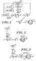
- FIG. 1 shows an embodiment of the invention in the form of an ophthalmoscope.
- a laser illumination source 11 produces a narrow incident light beam which passes through an anamorphic beam shaping system 13, 15 which produces a beam focused along a first axis and diverging along an axis normal to the first axis. This beam, in turn, impinges on a small turning mirror 14.
- the mirror 14 directs the incident laser beam onto the reflecting surface of a galvanometer deflection scanner 17 to produce a vertical scanning motion. From the galvanometer deflection scanner 17, the laser input beam is directed onto a focusing mirror 18, for conjugating the galvanometer 17 to the pupil 19c.
- the incident beam also passed through the crystalline lens of the eye 19b.
- the reflected light from the fundus 19a is directed back over a common portion of the foregoing optical input path, which includes focusing mirror 18, and vertical scanner 17. Both of these common elements can be mirrors and hence do not contribute reflections of the input beam back to the detector as noise background.
- the reflected output beam from the scanner 17 in large part passes by the turning mirror and hence separates from further traverse along the input optical path. Instead the output beam is directed through focusing lens 20 onto an optical detector array 21.
- the detector 21 is electrically connected to an electrical instrumentation unit 22 which provides electrical control signals to the laser source 11 and electrical drive signals to the scanning deflection element 17.
- the instrumentation unit provides synchronization of the signals received at the scanning element 17 so that the temporal order of the signals produced by the detector 21 can be correlated with the location of the scanned incident laser beam on the surface of the fundus.
- the detector 21 is a multi-element detector having discrete detection elements dispersed along the horizontal axis. It responds to incident light by providing from each discrete horizontal element a time varying electrical signal.
- a signal processor 16 which processes the data representing simultaneous reflections from a horizontally extended beam correlated with the variation in time as that beam is scanned vertically to produce signals suitable for creating a raster display.
- the control and synchronization which the processor and instrumentation unit provide enables a display device 23, such as a television raster device, to form a two-dimensional display of an image of the eye fundus 19a, in response to the reflected optical energy it receives.
- the detector signal may be applied to a long term storage element 24, such as a video tape recorder, for subsequent readout and display.
- the output signal may be compared to predetermined patterns of signal for eye identification, disease screening or the like. These patterns may be stored time varying signals from specific detector locations.
- the laser 11 can be any suitable laser light source which provides emission at frequencies yielding appropriate contrast for the fundus, or other target.
- the laser 11 is an Argon-Krypton laser or Helium-Neon laser operated at a power level to produce an illumination irradiance of one hundred microwatts per square centimeter or substantially less at the fundus.
- the laser 11 may also be selected to emit in the infrared wavelength region to provide a scanning beam which is not perceptible to the subject. For these irradiances the eye pupil need not be medically dilated to obtain an image of the fundus.
- two lasers of different wavelengths may be employed and converted into a single beam with a dichroic beam splitter.
- the purpose of the input optical system is to scan the fundus along a first axis with a rectangular optical beam having a low "height to width” aspect ratio to illuminate a "vertical" sequence of these line-like rectangular areas across the fundus surface in a known pattern so that the reflected light detected in time sequence can be electrically converted to a two-dimensional representation of the reflection characteristics of the fundus.
- the first axis could be horizontal so that it would be the "width to height" aspect ratio which would be low.
- the input optical system forms the incident laser beam with a cross sectional area of substantially 0.9 mm diameter at the entrance pupil of the eye and focused on the fundus to produce an illuminated segment approximately twelve microns by 6 mm.
- the vertical scanning motion in the illustrated preferred embodiment is introduced by a deflection galvanometer 17 that provides a scan action which corresponds with the television vertical scan of 60 Hz.
- Galvanometer controls such as those manufactured by General Scanning of Watertown, Massachusetts, are suitable for driving and controlling the position of th galvanometer mirror.
- the mirror 17 can, for example, be a type G120D or G325D General Scanning mirror.
- the deflection galvanometer could be replaced by a slow rotating polygon.
- the shaped laser beam must be in (vertical) focus at the retina, and the scan waist must be located (approximately) at the pupil of the eye. Under these circumstances the beam cross section on the retina is appropriate for the available resolution, and the image will appear in focus at the TV screen even if it is not in focus at the confocal aperture. It is the focus of the incident beam which determines the picture's resolution and the focus of the return beam (at the confocal stop) which controls contrast.
- the system is confocal only in the scanning (vertical) dimension, hence the statement applies only to that dimension. The fact that these controls are largely orthongonal is what allows flexibility as to mode of view.
- the turning mirror 14 preferably is a stationary mirror reflector. It is small in size in order to produce a minimal shadow in the output beam, and hence preferably is only large enough to intercept the input beam which the focusing element 13 and cylindrical lens 15 direct, via the turning mirror, to the scanner 17. In the configuration shown the turning mirror acts as the beam separator between the input and reflected return beam.
- FIGs. 2 and 3 illustrate features of the input optical system.
- Figure 2 represents the vertical aspect of the input beam with the scanner 17 assumed to be stationary in a neutral, non-deflecting, position.
- the narrow collimated incident beam from the laser is shaped by lens 13 and directed onto cylindrical lens 15.
- the cylindrical lens is positioned such that it focuses on the vertical axis (which is the axis illustrated in Figure 2).
- the focused beam from the cylindrical lens 15 is then reflected from turning mirror 14 onto deflecting galvanometer mirror 17 which directs it onto the face of relay mirror 18 which focuses the cross sectional beam on the retina 19a of the eye 19.
- the scanning axis is the vertical axis and the extended beam from the cylindrical lens is horizontal, this is an arbitrary choice, and the system could be arranged in the opposite fashion.
- Figure 3 is again a beam diagram of the same optical configuration as Figure 2, representing however the view along the horizontal axis.
- the beam from the cylindrical lens 15 is focused on the galvanometer reflecting surface 17 and on the pupil of the eye.
- the foci are at the optical conjugates of the retina , in Figure 3 they are at the conjugates of the pupil .
- the turning mirror 14 which is small compared to the pupil of the eye, typically being less than 0.9 mm, is positioned sufficiently close to the cylindrical lens so that the horizontal extension of the beam location of the turning mirror is not greater than the dimension of that mirror.
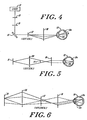
- Figure 4 which represents scan features of the input system, illustrates the input beam instantaneously as a single ray which the scanning element moves in the vertical direction as a function of time.
- the drawing shows, in effect, the time exposure on the vertical axis which, for the scanned input beam includes the entrance pupil.
- the scan angle is the full angle of this envelope in the plane of the scan.
- the mirror 18 is spherical and large so that even at f/2 (for the scan) the eye's pupil is far back from the optics. With human subjects there are some inflexible dimensions.
- the mirror is spherical because no aspheric is correct for both beam and scan systems at all points. That constraint can be understood by noting that the beam on one side of this mirror may be always collimated, no matter where it hits the mirror. So the mirror must have everywhere the same local curvature-which implies a sphere.
- a major portion of the output optical system has a common optical path with the input system.
- This common path includes both the scanning element 17 and the focusing mirror 18.
- light reflected from the galvanometer mirror 17 passes around the turning mirror 14 and is incident on the detector system which includes lens 20 and detector 21.
- Figure 5 represents the output beam along the vertical axis in the same manner as the representation in Figure 2, while Figure 6 represents the same output beam along the horizontal axis in the same manner as Figure 3.
- the reflected beam from the fundus has an exit aperture large compared to the vertical dimension of the scanning beam, preferably substantially the entire pupil of the eye, with a diameter of as much as nine mm.
- the image of this aperture at its conjugate plane also is nine mm. Absent magnification, the reflected output beam from the illuminated area on the fundus likewise is approximately nine mm in diameter at any conjugate of the exit pupil, which is where the scan element 17 is located.
- the ophthalmoscope can have a small entrance pupil, as described above, due to the large radiance of the incident beam.
- the output beam has relatively low radiance, and hence the provision of this large output pupil is desired to collect a maximal amount of output light energy.
- the large exit aperture hence enhances the high efficiency of the instrument. It also facilitates viewing a large portion of the eye fundus.
- Figure 5 also illustrates, with exaggerated scale, that the output beam passes around the turning mirror 14, which hence casts a small shadow generally of low significance.
- Figure 6 illustrates the reflected beam from the fundus along its horizontal axis.
- the field lens 20 is placed at the pupillary conjugate plane while the detector 21 is placed at a retinal conjugate plane.
- the image of the retina at the plane of the detector 21 is the portion of the illuminated area which at any instant in time has an extended width and a very low height.
- An ideal detector 21 is then an array of very small discrete elements dispersed horizontally and having a low vertical height.
- One suitable detector for this configuration is a series of charged coupled detectors providing, for example, 512 discrete horizontal elements.
- the output signals are then taken in parallel from each of the elements.
- the time variance at each element represents the change in the retinal image as the line of illumination is scanned in the vertical direction.
- the output electrical signals can be transmitted to a processor 16 which can transfer the processed information into a storage unit 24, to a display 23, which would typically be a television raster, or to further pattern recognition means.
- Figure 7 is a ray diagram of the scanning envelope of vertical dimension of the output reflected beam.
- the system described herein has many of the advantages of a double scanning confocal ophthalmoscope. It is confocal in one dimension, and has the advantage of using the identical optical path for the reflected beam, which is descanned at the reflecting galvanometer mirror. The positioning of the turning mirror as a small centrally located mirror in the reflected beam provides that very little light intensity is lost and that corneal reflections are blocked. Since the contrast enhancement is in the ratio of observed to illuminated retina, this system improves contrast by 512, while a fully double scanning optimum improves it by (512)2.
- One clear advantage of the system as illustrated is the simplicity and cost effectiveness resulting from including only one scanning element.
- FIG. 8 in which the vertical galvanometer is replaced with a dove prism or a Dove mirror (the mirror analogue of a Dove prism) which is rotated at a predetermined speed to produce at the retina, a polar scanning line shaped beam and, at the output detector, a signal which varies in time in accordance with the polar scan.
- a dove prism or a Dove mirror the mirror analogue of a Dove prism
- the apparatus has other uses, for example, for eye recognition, the detected information in either the polar scan or the rectilinear scan configuration can be matched against previously recorded information for an individual retina, thus providing determination of the identity or lack of identity of the person. Similarly, patients can be screened to determine whether there are specific characteristics of the retina indicating broad categories of disease, or change of condition. In these applications information developed by the detector and processor would be either visually screened or processed electronically to determine whether specific areas of the retina are characterized by specific images or changes in images.
Abstract
Description
- This invention relates in general to optical instruments and methods, and more particularly to an instrument for scanning a surface or other structure with an optical beam, detecting the light emitted from the structure, and generating either a two-dimensional representation of an image of the structure or a set of stored data representing such an image.
- In the art of optical instruments, it is known to scan a surface to be imaged with a small light source, collect the light reflected from the illuminated spot and direct it to a detector which provides an output signal varying in time in correlation with the scanning of the illuminated spot across the surface. The detector output can be stored in a permanent storage medium or provided directly to a scanning display device, such as a television raster or a cathode ray tube display. By synchronizing the scanning operation of the illuminating source with the scanning of the display signals, a two dimensional image is produced.
- One such instrument is a scanning ophtalmoscope which produces an image of the fundus of the eye. It has been found that the use of a laser light source provides improved imaging in an ophthalmoscope. A laser scanning ophthalmoscope is described in U.S. Patent No. 4,213,678.
- In a device as described in the noted patent, the entrance pupil for the scanning laser beam has a small cross sectional area within the pupil of the eye, typically 0.9 mm in diameter, whereas the exit aperture for the reflected light is the overall pupil of the eye, whch typically is nine mm in diameter. The detector is placed in a plane conjugate to this exit aperture.
- An improved technique is described in pending U.S. Application Serial No. 876,230 filed June 19, 1986 and U.S. Application Serial No. 876,231 filed June 19, 1986.
- Broadly speaking, in the present invention a confocal scanning ophthalmoscope which scans along only one coordinate is constructed utilizing a laser source, an asymmetrical focusing element, such as a cylindrical lens, together with a deflection galvanometer or other scanning element for scanning on the same axis for which the asymmetrical element focuses. The laser beam which is of generally circular cross section and small compared to the diameter of an eye pupil is directed onto the cylindrical lens, which focuses on the vertical axis but does not focus along the horizontal axis so that what is produced at the focal point of the cylindrical lens is a vertically focused horizontal extended rectangular beam characterized by a low vertical to horizontal aspect ratio. In other words it appears to be a horizontal line beam. This beam is directed by a small turning mirror onto a deflection galvanometer or other vertical scanning means which scans it along a vertical coordinate. The scanning beam is directed by means of another focusing element, preferably a mirror, through the eye pupil and onto the fundus of the eye, the focal length being arranged such that the beam as it passes through the pupil is focused to a narrow waist, substantially smaller than the diameter of the eye pupil, and then expands back to the width of the horizontal beam for scanning the fundus. The overall input beam system then scans the line beam vertically over the fundus, thereby scanning an area of the fundus.
- The light reflected from the area of the fundus illuminated by the beam is collected by the focusing mirror and directed back to the vertical deflection mirror, which is positioned so that its face is approximately conjugate with the plane of the eye pupil. The turning mirror is placed in the center of the reflected beam and since it's diameter is very small compared to the cross sectional area of the beam as it leaves the galvanometer mirror, it intercepts only a very small portion of the reflected light. The major portion of this reflected output beam then passes by the turning mirror to a lens placed at the pupillary conjugate which focuses it onto a horizontally distributed line of detectors located at a retinal conjugate plane. The detectors produce a plurality of electrical signals representing the time variation of light arriving at each one of the horizontally distributed detectors. This electrical signal can then be used to develop a raster display or for optical pattern recognition.
- Embodiments of the present invention will now be described, by way of example, with reference to the accompanying drawings, in which:-
- Fig. 1 is a diagrammatic representation of one embodiment of a scanning instrument according to the principles of this invention;
- Figs. 2 and 3 are explanatory ray diagrams of optical beam features of the embodiment illustrated in Fig. 1;
- Fig. 4 is an explanatory ray diagram of optical scan features of the embodiment of Fig. 1;
- Figs. 5 and 6 are also explanatory ray diagrams of optical beam features of the invention illustrated in Fig. 1;
- Fig. 7 is an explanatory ray diagram of the reflected optical beam of the embodiment illustrated in Fig. 1; and
- Fig. 8 is a diagrammatic illustration of a second embodiment of an optical instrument constructed in accordance with the principles of this invention.
- Figure 1 shows an embodiment of the invention in the form of an ophthalmoscope. A laser illumination source 11 produces a narrow incident light beam which passes through an anamorphic
beam shaping system small turning mirror 14. Themirror 14 directs the incident laser beam onto the reflecting surface of agalvanometer deflection scanner 17 to produce a vertical scanning motion. From thegalvanometer deflection scanner 17, the laser input beam is directed onto a focusingmirror 18, for conjugating thegalvanometer 17 to thepupil 19c. The incident beam also passed through the crystalline lens of theeye 19b. - The reflected light from the fundus 19a is directed back over a common portion of the foregoing optical input path, which includes focusing
mirror 18, andvertical scanner 17. Both of these common elements can be mirrors and hence do not contribute reflections of the input beam back to the detector as noise background. The reflected output beam from thescanner 17 in large part passes by the turning mirror and hence separates from further traverse along the input optical path. Instead the output beam is directed through focusinglens 20 onto anoptical detector array 21. - The
detector 21 is electrically connected to anelectrical instrumentation unit 22 which provides electrical control signals to the laser source 11 and electrical drive signals to thescanning deflection element 17. In essence, the instrumentation unit provides synchronization of the signals received at thescanning element 17 so that the temporal order of the signals produced by thedetector 21 can be correlated with the location of the scanned incident laser beam on the surface of the fundus. Thedetector 21 is a multi-element detector having discrete detection elements dispersed along the horizontal axis. It responds to incident light by providing from each discrete horizontal element a time varying electrical signal. These signals are provided to asignal processor 16, which processes the data representing simultaneous reflections from a horizontally extended beam correlated with the variation in time as that beam is scanned vertically to produce signals suitable for creating a raster display. The control and synchronization which the processor and instrumentation unit provide enables adisplay device 23, such as a television raster device, to form a two-dimensional display of an image of the eye fundus 19a, in response to the reflected optical energy it receives. The detector signal may be applied to a longterm storage element 24, such as a video tape recorder, for subsequent readout and display. Alternatively the output signal may be compared to predetermined patterns of signal for eye identification, disease screening or the like. These patterns may be stored time varying signals from specific detector locations. For a description of a suitable electrical timing and control circuit, reference is made to U.S. Patent 4,213,678 whch is incorporated herein by reference. If the detector is a charge coupled detector, it may integrate for only 63 microseconds. This requires different, but well understood, timing circuitry. - The laser 11 can be any suitable laser light source which provides emission at frequencies yielding appropriate contrast for the fundus, or other target. Typically, the laser 11 is an Argon-Krypton laser or Helium-Neon laser operated at a power level to produce an illumination irradiance of one hundred microwatts per square centimeter or substantially less at the fundus. The laser 11 may also be selected to emit in the infrared wavelength region to provide a scanning beam which is not perceptible to the subject. For these irradiances the eye pupil need not be medically dilated to obtain an image of the fundus. For color imaging two lasers of different wavelengths may be employed and converted into a single beam with a dichroic beam splitter.
- The purpose of the input optical system is to scan the fundus along a first axis with a rectangular optical beam having a low "height to width" aspect ratio to illuminate a "vertical" sequence of these line-like rectangular areas across the fundus surface in a known pattern so that the reflected light detected in time sequence can be electrically converted to a two-dimensional representation of the reflection characteristics of the fundus. Of course the first axis could be horizontal so that it would be the "width to height" aspect ratio which would be low. In one illustrative instrument, the input optical system forms the incident laser beam with a cross sectional area of substantially 0.9 mm diameter at the entrance pupil of the eye and focused on the fundus to produce an illuminated segment approximately twelve microns by 6 mm.
- The vertical scanning motion in the illustrated preferred embodiment is introduced by a
deflection galvanometer 17 that provides a scan action which corresponds with the television vertical scan of 60 Hz. Galvanometer controls, such as those manufactured by General Scanning of Watertown, Massachusetts, are suitable for driving and controlling the position of th galvanometer mirror. Themirror 17 can, for example, be a type G120D or G325D General Scanning mirror. The deflection galvanometer could be replaced by a slow rotating polygon. - The shaped laser beam must be in (vertical) focus at the retina, and the scan waist must be located (approximately) at the pupil of the eye. Under these circumstances the beam cross section on the retina is appropriate for the available resolution, and the image will appear in focus at the TV screen even if it is not in focus at the confocal aperture. It is the focus of the incident beam which determines the picture's resolution and the focus of the return beam (at the confocal stop) which controls contrast. The system, however, is confocal only in the scanning (vertical) dimension, hence the statement applies only to that dimension. The fact that these controls are largely orthongonal is what allows flexibility as to mode of view.
- The turning
mirror 14 preferably is a stationary mirror reflector. It is small in size in order to produce a minimal shadow in the output beam, and hence preferably is only large enough to intercept the input beam which the focusingelement 13 andcylindrical lens 15 direct, via the turning mirror, to thescanner 17. In the configuration shown the turning mirror acts as the beam separator between the input and reflected return beam. - Figs. 2 and 3 illustrate features of the input optical system. Figure 2 represents the vertical aspect of the input beam with the
scanner 17 assumed to be stationary in a neutral, non-deflecting, position. The narrow collimated incident beam from the laser is shaped bylens 13 and directed ontocylindrical lens 15. The cylindrical lens is positioned such that it focuses on the vertical axis (which is the axis illustrated in Figure 2). The focused beam from thecylindrical lens 15 is then reflected from turningmirror 14 onto deflectinggalvanometer mirror 17 which directs it onto the face ofrelay mirror 18 which focuses the cross sectional beam on the retina 19a of theeye 19. It will be understood that, while the scanning axis is the vertical axis and the extended beam from the cylindrical lens is horizontal, this is an arbitrary choice, and the system could be arranged in the opposite fashion. - Figure 3 is again a beam diagram of the same optical configuration as Figure 2, representing however the view along the horizontal axis. Thus, along this axis, the beam from the
cylindrical lens 15 is focused on thegalvanometer reflecting surface 17 and on the pupil of the eye. (Thus, while in Figure 2, the foci are at the optical conjugates of the retina, in Figure 3 they are at the conjugates of the pupil.) The turningmirror 14 which is small compared to the pupil of the eye, typically being less than 0.9 mm, is positioned sufficiently close to the cylindrical lens so that the horizontal extension of the beam location of the turning mirror is not greater than the dimension of that mirror. What is reflected from the turningmirror 14 is then, in the horizontal dimension, an extended line which is in turn focused by therelay mirror 18 onto the eye'spupil 19c. It spreads into a line at the retina. The beam cross section as it arrives at the retina has a generally rectangular shape with a very low aspect ratio of vertical dimension to horizontal dimension (a horizontal line). This horizontal line beam is scanned in a vertical direction over the retina surface by the action of the deflectinggalvanometer mirror 17. Since the line at the retina may have a gaussian profile, it will be necessary to put in a stop at 18a to give it crisper ends. - Figure 4 which represents scan features of the input system, illustrates the input beam instantaneously as a single ray which the scanning element moves in the vertical direction as a function of time. The drawing shows, in effect, the time exposure on the vertical axis which, for the scanned input beam includes the entrance pupil. The scan angle is the full angle of this envelope in the plane of the scan.
- The
mirror 18 is spherical and large so that even at f/2 (for the scan) the eye's pupil is far back from the optics. With human subjects there are some inflexible dimensions. The mirror is spherical because no aspheric is correct for both beam and scan systems at all points. That constraint can be understood by noting that the beam on one side of this mirror may be always collimated, no matter where it hits the mirror. So the mirror must have everywhere the same local curvature-which implies a sphere. - As described, a major portion of the output optical system has a common optical path with the input system. This common path includes both the
scanning element 17 and the focusingmirror 18. In the output system light reflected from thegalvanometer mirror 17 passes around the turningmirror 14 and is incident on the detector system which includeslens 20 anddetector 21. - Figure 5 represents the output beam along the vertical axis in the same manner as the representation in Figure 2, while Figure 6 represents the same output beam along the horizontal axis in the same manner as Figure 3.
- As illustrated in Figure 5, the reflected beam from the fundus has an exit aperture large compared to the vertical dimension of the scanning beam, preferably substantially the entire pupil of the eye, with a diameter of as much as nine mm. The image of this aperture at its conjugate plane also is nine mm. Absent magnification, the reflected output beam from the illuminated area on the fundus likewise is approximately nine mm in diameter at any conjugate of the exit pupil, which is where the
scan element 17 is located. - In this configuration the central region of the eye's pupil is used as an entrance pupil and the remaining annulus an exit pupil, thus conforming to Gulstrand's principle. This means that
scanner 17, optically conjugate to the pupil, needs to be big enough to intercept that larger return beam. For the vertical scanner which moves as a 60 Hz sawtooth, a 10-15 mm mirror is suitable. - The ophthalmoscope can have a small entrance pupil, as described above, due to the large radiance of the incident beam. The output beam, however, has relatively low radiance, and hence the provision of this large output pupil is desired to collect a maximal amount of output light energy. The large exit aperture hence enhances the high efficiency of the instrument. It also facilitates viewing a large portion of the eye fundus.
- Figure 5 also illustrates, with exaggerated scale, that the output beam passes around the turning
mirror 14, which hence casts a small shadow generally of low significance. - It is desirable to separate the incident and return beams as close to the scanning mirror as possible in order to place the incident beam in the center of the return beam and thus stop direct reflection from the cornea (and spectacles if desired) from reaching the detector.
- Figure 6 illustrates the reflected beam from the fundus along its horizontal axis. In both figures the
field lens 20 is placed at the pupillary conjugate plane while thedetector 21 is placed at a retinal conjugate plane. Thus the image of the retina at the plane of thedetector 21 is the portion of the illuminated area which at any instant in time has an extended width and a very low height. Anideal detector 21 is then an array of very small discrete elements dispersed horizontally and having a low vertical height. One suitable detector for this configuration is a series of charged coupled detectors providing, for example, 512 discrete horizontal elements. The output signals are then taken in parallel from each of the elements. The time variance at each element represents the change in the retinal image as the line of illumination is scanned in the vertical direction. The output electrical signals can be transmitted to aprocessor 16 which can transfer the processed information into astorage unit 24, to adisplay 23, which would typically be a television raster, or to further pattern recognition means. - Figure 7 is a ray diagram of the scanning envelope of vertical dimension of the output reflected beam.
- Although specific block diagrams have not been provided for the circuitry components and for the process and logic, it is believed that synchronizing the raster scan with the galvanometer mirror oscillation and the processing of the time variant signals to produce a raster scan is well known to those skilled in the art. Reference is also made to copending U.S. Application Serial No. 876,230, which is incorporated herein by reference.
- The system described herein has many of the advantages of a double scanning confocal ophthalmoscope. It is confocal in one dimension, and has the advantage of using the identical optical path for the reflected beam, which is descanned at the reflecting galvanometer mirror. The positioning of the turning mirror as a small centrally located mirror in the reflected beam provides that very little light intensity is lost and that corneal reflections are blocked. Since the contrast enhancement is in the ratio of observed to illuminated retina, this system improves contrast by 512, while a fully double scanning optimum improves it by (512)². One clear advantage of the system as illustrated is the simplicity and cost effectiveness resulting from including only one scanning element.
- While the embodiments as described have generated a rectangular raster scan, it is possible by employing a rotational optical element to generate a polar scan rather than a vertical deflection. Thus, in a configuration is shown in Figure 8 in which the vertical galvanometer is replaced with a dove prism or a Dove mirror (the mirror analogue of a Dove prism) which is rotated at a predetermined speed to produce at the retina, a polar scanning line shaped beam and, at the output detector, a signal which varies in time in accordance with the polar scan.
- While the system has been described in terms of presenting a visual image of the fundus. The apparatus has other uses, for example, for eye recognition, the detected information in either the polar scan or the rectilinear scan configuration can be matched against previously recorded information for an individual retina, thus providing determination of the identity or lack of identity of the person. Similarly, patients can be screened to determine whether there are specific characteristics of the retina indicating broad categories of disease, or change of condition. In these applications information developed by the detector and processor would be either visually screened or processed electronically to determine whether specific areas of the retina are characterized by specific images or changes in images.
Claims (12)
a laser source for generating a laser beam of defined symmetrical cross sectional area which is small compared to an area of the fundus to be scanned,
an optical system for directing said laser beam through the pupil of the eye onto said fundus area, and for directing light reflected from the portion of said fundus area illuminated by said laser beam, onto a detector, said optical system including,
an anamorphic optical element positioned to produce an output beam focused on a first axis and dispersed on a second axis normal to said first axis, forming a line at the focal point,
a scanning element positioned to receive said anamorphic element output beam and move said beam along said first axis to scan said beam on a first coordinate across an area of said fundus,
a focusing element for directing said anamorphic element output beam from said scanning element through the eye pupil onto the fundus area, such that said beam passes through the plane of the pupil of the eye and has at that plane a small cross sectional area compared to the diameter of the pupil, said focusing element being positioned to produce at said scanning element a conjugate image of said eye pupil,
an exit aperture for reflected light from said fundus area illuminated by said beam, said exit aperture being large compared to the cross sectional dimension of said input beam at said pupillary plane,
a detector means for generating a signal varying in time with variation in the amount of light received by it, said detector means including a series of discrete detector elements extending along one coordinate such that it provides in each discrete element a time varying signal corresponding to the variations in time of the amount of light received by that element,
beam separating means positioned to direct the anamorphic element output beam toward said scanning element and to direct the reflected light from said scanned fundus area toward said detector, said detector being positioned at a retinal conjugate of said eye and said coordinate along which said discrete detector elements extend being aligned with the extended axis of said anamorphic element output beam on said fundus, and
signal processing means for processing said time varying signals from said discrete elements to provide from said signals said two dimensional output representation of the reflection characteristics of said eye fundus.
Applications Claiming Priority (2)
| Application Number | Priority Date | Filing Date | Title |
|---|---|---|---|
| US07/095,307 US4768874A (en) | 1987-09-10 | 1987-09-10 | Scanning optical apparatus and method |
| US95307 | 1987-09-10 |
Publications (2)
| Publication Number | Publication Date |
|---|---|
| EP0307185A2 true EP0307185A2 (en) | 1989-03-15 |
| EP0307185A3 EP0307185A3 (en) | 1989-10-11 |
Family
ID=22251296
Family Applications (1)
| Application Number | Title | Priority Date | Filing Date |
|---|---|---|---|
| EP88308272A Ceased EP0307185A3 (en) | 1987-09-10 | 1988-09-07 | Scanning optical apparatus |
Country Status (3)
| Country | Link |
|---|---|
| US (1) | US4768874A (en) |
| EP (1) | EP0307185A3 (en) |
| JP (1) | JPH01106012A (en) |
Cited By (9)
| Publication number | Priority date | Publication date | Assignee | Title |
|---|---|---|---|---|
| DE4102404A1 (en) * | 1991-01-28 | 1992-07-30 | Alexander Dr Zarubin | Optical scanner producing Fourier transform hologram - performs real=time correlation of intensity distribution of hologram recorded e.g. by CCD camera |
| DE19722790A1 (en) * | 1997-05-30 | 1998-12-03 | Zeiss Carl Jena Gmbh | Laser scanning ophthalmoscope |
| EP0904004A1 (en) * | 1996-04-15 | 1999-03-31 | Gregory Lee Heacock | Portable scanning laser ophthalmoscope |
| WO2003105679A1 (en) * | 2002-06-14 | 2003-12-24 | Physical Sciences, Inc. | Line-scan laser ophthalmoscope |
| US7648242B2 (en) | 2006-05-01 | 2010-01-19 | Physical Sciences, Inc. | Hybrid spectral domain optical coherence tomography line scanning laser ophthalmoscope |
| US7758189B2 (en) | 2006-04-24 | 2010-07-20 | Physical Sciences, Inc. | Stabilized retinal imaging with adaptive optics |
| US8201943B2 (en) | 2009-01-15 | 2012-06-19 | Physical Sciences, Inc. | Adaptive optics line scanning ophthalmoscope |
| US8696122B2 (en) | 2010-01-21 | 2014-04-15 | Physical Sciences, Inc. | Multi-functional adaptive optics retinal imaging |
| CN111163684A (en) * | 2017-08-14 | 2020-05-15 | 奥普托斯股份有限公司 | Ophthalmologic apparatus |
Families Citing this family (32)
| Publication number | Priority date | Publication date | Assignee | Title |
|---|---|---|---|---|
| JP2618912B2 (en) * | 1987-08-31 | 1997-06-11 | 興和株式会社 | Fundus examination device |
| EP1245987B1 (en) | 1988-07-13 | 2008-01-23 | Optiscan Pty Ltd | Scanning confocal microscope |
| JP3035336B2 (en) * | 1990-11-27 | 2000-04-24 | 興和株式会社 | Blood flow measurement device |
| CA2073802C (en) * | 1991-08-16 | 2003-04-01 | John Shimmick | Method and apparatus for combined cylindrical and spherical eye corrections |
| US6008781A (en) * | 1992-10-22 | 1999-12-28 | Board Of Regents Of The University Of Washington | Virtual retinal display |
| US5467104A (en) * | 1992-10-22 | 1995-11-14 | Board Of Regents Of The University Of Washington | Virtual retinal display |
| GB9323065D0 (en) * | 1993-11-09 | 1994-01-05 | Besca Ltd | A wide field retinal scanning ophthalmoscope |
| US5535679A (en) * | 1994-12-20 | 1996-07-16 | Loral Vought Systems Corporation | Low velocity radial deployment with predetermined pattern |
| US5880880A (en) * | 1995-01-13 | 1999-03-09 | The General Hospital Corp. | Three-dimensional scanning confocal laser microscope |
| US5788639A (en) * | 1995-07-13 | 1998-08-04 | Lucid Technologies, Inc. | Confocal imaging through thick dermal tissue |
| US7047064B1 (en) | 1995-07-13 | 2006-05-16 | Lucid, Inc. | Microscopic imaging apparatus and method |
| US6263233B1 (en) | 1995-07-13 | 2001-07-17 | Lucid, Inc. | Handheld imaging microscope |
| US5784148A (en) * | 1996-04-09 | 1998-07-21 | Heacock; Gregory Lee | Wide field of view scanning laser ophthalmoscope |
| US5867251A (en) * | 1997-05-02 | 1999-02-02 | The General Hospital Corp. | Scanning ophthalmoscope with spatial light modulators |
| EP1925961B1 (en) | 1997-06-30 | 2017-03-29 | Lucid, Inc. | Confocal imaging through thick dermal tissues |
| US5861939A (en) * | 1997-10-16 | 1999-01-19 | Odyssey Optical Systems, Llc | Portable fundus viewing system for an undilated eye |
| US5997141A (en) * | 1998-03-06 | 1999-12-07 | Odyssey Optical Systems, Llc | System for treating the fundus of an eye |
| US7331669B2 (en) * | 2001-10-16 | 2008-02-19 | Indiana University Research And Technology Corporation | Device for digital retinal imaging |
| US7365856B2 (en) | 2005-01-21 | 2008-04-29 | Carl Zeiss Meditec, Inc. | Method of motion correction in optical coherence tomography imaging |
| US7805009B2 (en) | 2005-04-06 | 2010-09-28 | Carl Zeiss Meditec, Inc. | Method and apparatus for measuring motion of a subject using a series of partial images from an imaging system |
| US9055867B2 (en) | 2005-05-12 | 2015-06-16 | Caliber Imaging & Diagnostics, Inc. | Confocal scanning microscope having optical and scanning systems which provide a handheld imaging head |
| US8488895B2 (en) * | 2006-05-31 | 2013-07-16 | Indiana University Research And Technology Corp. | Laser scanning digital camera with pupil periphery illumination and potential for multiply scattered light imaging |
| US20090009715A1 (en) * | 2007-07-04 | 2009-01-08 | I-Optics Bv | Confocal Color Ophthalmoscope |
| GB2451441B (en) * | 2007-07-30 | 2012-07-11 | Lein Applied Diagnostics Ltd | Optical alignment apparatus and method thereof |
| JP2010175448A (en) | 2009-01-30 | 2010-08-12 | Kowa Co | Optical imaging device |
| NL2005253C2 (en) | 2010-08-23 | 2012-02-27 | Optics B V I | Confocal line-scan ophthalmoscope. |
| US9033510B2 (en) | 2011-03-30 | 2015-05-19 | Carl Zeiss Meditec, Inc. | Systems and methods for efficiently obtaining measurements of the human eye using tracking |
| WO2013004801A1 (en) | 2011-07-07 | 2013-01-10 | Carl Zeiss Meditec Ag | Improved data acquisition methods for reduced motion artifacts and applications in oct angiography |
| JP6057567B2 (en) | 2011-07-14 | 2017-01-11 | キヤノン株式会社 | Imaging control apparatus, ophthalmic imaging apparatus, imaging control method, and program |
| US9101294B2 (en) | 2012-01-19 | 2015-08-11 | Carl Zeiss Meditec, Inc. | Systems and methods for enhanced accuracy in OCT imaging of the cornea |
| US9456746B2 (en) | 2013-03-15 | 2016-10-04 | Carl Zeiss Meditec, Inc. | Systems and methods for broad line fundus imaging |
| JP6819773B2 (en) | 2016-09-06 | 2021-01-27 | 株式会社ニコン | Reflective refraction 1x afocal pupil relay and optical imaging system using this |
Citations (5)
| Publication number | Priority date | Publication date | Assignee | Title |
|---|---|---|---|---|
| US4109237A (en) * | 1977-01-17 | 1978-08-22 | Hill Robert B | Apparatus and method for identifying individuals through their retinal vasculature patterns |
| DE3041178A1 (en) * | 1979-10-31 | 1981-05-14 | National Research Development Corp., London | METHOD AND DEVICE FOR MEASURING RETINAL CIRCULATION |
| GB2112171A (en) * | 1981-12-18 | 1983-07-13 | Zeiss Stiftung | Device for examining anterior sections of the eye |
| EP0223356A2 (en) * | 1985-09-17 | 1987-05-27 | Eye Research Institute Of Retina Foundation | Two-dimensional eye fundus scanning apparatus |
| EP0279589A1 (en) * | 1987-02-17 | 1988-08-24 | Eye Research Institute Of Retina Foundation | Eye fundus tracker/stabilizer |
Family Cites Families (2)
| Publication number | Priority date | Publication date | Assignee | Title |
|---|---|---|---|---|
| US4213678A (en) * | 1977-09-29 | 1980-07-22 | Retina Foundation | Scanning ophthalmoscope for examining the fundus of the eye |
| DE3245939C2 (en) * | 1982-12-11 | 1985-12-19 | Fa. Carl Zeiss, 7920 Heidenheim | Device for generating an image of the fundus |
-
1987
- 1987-09-10 US US07/095,307 patent/US4768874A/en not_active Expired - Lifetime
-
1988
- 1988-09-07 EP EP88308272A patent/EP0307185A3/en not_active Ceased
- 1988-09-09 JP JP63224886A patent/JPH01106012A/en active Pending
Patent Citations (5)
| Publication number | Priority date | Publication date | Assignee | Title |
|---|---|---|---|---|
| US4109237A (en) * | 1977-01-17 | 1978-08-22 | Hill Robert B | Apparatus and method for identifying individuals through their retinal vasculature patterns |
| DE3041178A1 (en) * | 1979-10-31 | 1981-05-14 | National Research Development Corp., London | METHOD AND DEVICE FOR MEASURING RETINAL CIRCULATION |
| GB2112171A (en) * | 1981-12-18 | 1983-07-13 | Zeiss Stiftung | Device for examining anterior sections of the eye |
| EP0223356A2 (en) * | 1985-09-17 | 1987-05-27 | Eye Research Institute Of Retina Foundation | Two-dimensional eye fundus scanning apparatus |
| EP0279589A1 (en) * | 1987-02-17 | 1988-08-24 | Eye Research Institute Of Retina Foundation | Eye fundus tracker/stabilizer |
Cited By (17)
| Publication number | Priority date | Publication date | Assignee | Title |
|---|---|---|---|---|
| DE4102404A1 (en) * | 1991-01-28 | 1992-07-30 | Alexander Dr Zarubin | Optical scanner producing Fourier transform hologram - performs real=time correlation of intensity distribution of hologram recorded e.g. by CCD camera |
| EP0904004A1 (en) * | 1996-04-15 | 1999-03-31 | Gregory Lee Heacock | Portable scanning laser ophthalmoscope |
| EP0904004A4 (en) * | 1996-04-15 | 2000-07-12 | Odyssey Optical Systems Llc | Portable scanning laser ophthalmoscope |
| DE19722790A1 (en) * | 1997-05-30 | 1998-12-03 | Zeiss Carl Jena Gmbh | Laser scanning ophthalmoscope |
| DE19722790B4 (en) * | 1997-05-30 | 2006-01-05 | Carl Zeiss Jena Gmbh | Arrangement and method for time-resolved measurement according to the scanner principle |
| WO2003105679A1 (en) * | 2002-06-14 | 2003-12-24 | Physical Sciences, Inc. | Line-scan laser ophthalmoscope |
| US6758564B2 (en) | 2002-06-14 | 2004-07-06 | Physical Sciences, Inc. | Line-scan laser ophthalmoscope |
| US7758189B2 (en) | 2006-04-24 | 2010-07-20 | Physical Sciences, Inc. | Stabilized retinal imaging with adaptive optics |
| US7896496B2 (en) | 2006-04-24 | 2011-03-01 | Physical Sciences, Inc. | Stabilized retinal imaging with adaptive optics |
| US8444268B2 (en) | 2006-04-24 | 2013-05-21 | Physical Sciences, Inc. | Stabilized retinal imaging with adaptive optics |
| US7648242B2 (en) | 2006-05-01 | 2010-01-19 | Physical Sciences, Inc. | Hybrid spectral domain optical coherence tomography line scanning laser ophthalmoscope |
| US7866821B2 (en) | 2006-05-01 | 2011-01-11 | Physical Sciences, Inc. | Hybrid spectral domain optical coherence tomography line scanning laser ophthalmoscope |
| US8033665B2 (en) | 2006-05-01 | 2011-10-11 | Physical Sciences, Inc. | Hybrid spectral domain optical coherence tomography line scanning laser ophthalmoscope |
| US8770751B2 (en) | 2006-05-01 | 2014-07-08 | Physical Sciences, Inc. | Hybrid spectral domain optical coherence tomography line scanning laser ophthalmoscope |
| US8201943B2 (en) | 2009-01-15 | 2012-06-19 | Physical Sciences, Inc. | Adaptive optics line scanning ophthalmoscope |
| US8696122B2 (en) | 2010-01-21 | 2014-04-15 | Physical Sciences, Inc. | Multi-functional adaptive optics retinal imaging |
| CN111163684A (en) * | 2017-08-14 | 2020-05-15 | 奥普托斯股份有限公司 | Ophthalmologic apparatus |
Also Published As
| Publication number | Publication date |
|---|---|
| US4768874A (en) | 1988-09-06 |
| JPH01106012A (en) | 1989-04-24 |
| EP0307185A3 (en) | 1989-10-11 |
Similar Documents
| Publication | Publication Date | Title |
|---|---|---|
| US4768874A (en) | Scanning optical apparatus and method | |
| US4764005A (en) | Double scanning optical apparatus | |
| EP0223356B1 (en) | Two-dimensional eye fundus scanning apparatus | |
| US4768873A (en) | Double scanning optical apparatus and method | |
| US5861938A (en) | Portable scanning laser ophthalmoscope | |
| US5784148A (en) | Wide field of view scanning laser ophthalmoscope | |
| US4765730A (en) | Double scanning optical apparatus and method | |
| US4856891A (en) | Eye fundus tracker/stabilizer | |
| US4854692A (en) | Ophthalmic examination apparatus | |
| US4287410A (en) | Double Purkinje eye tracker | |
| US6003993A (en) | Scanning ophthalmoscope with spatial light modulators | |
| EP0462268A1 (en) | Imaging apparatus and methods utilizing scannable microlaser source. | |
| US5847805A (en) | Scan imaging device for forming a stereoscopic image of the eye | |
| KR100339259B1 (en) | Three dimensional real-time image apparatus of ocular retina | |
| US4960327A (en) | Optical system in a lasar scanning eye fundus camera | |
| CN113520299B (en) | Multi-modal eye imaging system | |
| CN111657853B (en) | High-speed self-adaptive line scanning fundus imaging system and method | |
| US4893920A (en) | Optical scanning system and method including correction for cross scan error | |
| US5663781A (en) | Apparatus for the examination of objects and the determination of topography | |
| JP7441588B2 (en) | Improvement of slit scanning fundus imaging device | |
| WO2002007068A1 (en) | An authentication device for forming an image of at least a partial area of an eye retina | |
| JP2740514B2 (en) | Laser scan fundus camera | |
| CA1275825C (en) | Double scanning optical apparatus | |
| CN111643050A (en) | Ophthalmic optical imaging system | |
| JPH0759737A (en) | Ophthalmologic measuring apparatus |
Legal Events
| Date | Code | Title | Description |
|---|---|---|---|
| PUAI | Public reference made under article 153(3) epc to a published international application that has entered the european phase |
Free format text: ORIGINAL CODE: 0009012 |
|
| AK | Designated contracting states |
Kind code of ref document: A2 Designated state(s): AT BE CH DE ES FR GB GR IT LI LU NL SE |
|
| PUAL | Search report despatched |
Free format text: ORIGINAL CODE: 0009013 |
|
| AK | Designated contracting states |
Kind code of ref document: A3 Designated state(s): AT BE CH DE ES FR GB GR IT LI LU NL SE |
|
| 17P | Request for examination filed |
Effective date: 19900214 |
|
| 17Q | First examination report despatched |
Effective date: 19920323 |
|
| STAA | Information on the status of an ep patent application or granted ep patent |
Free format text: STATUS: THE APPLICATION HAS BEEN REFUSED |
|
| 18R | Application refused |
Effective date: 19930803 |