EP0308881A2 - Radio-controlled watch - Google Patents
Radio-controlled watch Download PDFInfo
- Publication number
- EP0308881A2 EP0308881A2 EP88115451A EP88115451A EP0308881A2 EP 0308881 A2 EP0308881 A2 EP 0308881A2 EP 88115451 A EP88115451 A EP 88115451A EP 88115451 A EP88115451 A EP 88115451A EP 0308881 A2 EP0308881 A2 EP 0308881A2
- Authority
- EP
- European Patent Office
- Prior art keywords
- display
- time
- radio
- alarm
- information
- Prior art date
- Legal status (The legal status is an assumption and is not a legal conclusion. Google has not performed a legal analysis and makes no representation as to the accuracy of the status listed.)
- Granted
Links
- 230000011664 signaling Effects 0.000 claims description 6
- 230000000737 periodic effect Effects 0.000 claims description 3
- 230000001960 triggered effect Effects 0.000 claims description 3
- 230000004913 activation Effects 0.000 claims 1
- 238000010586 diagram Methods 0.000 description 2
- 230000033764 rhythmic process Effects 0.000 description 2
- 238000012790 confirmation Methods 0.000 description 1
- 238000011161 development Methods 0.000 description 1
- 230000018109 developmental process Effects 0.000 description 1
- 230000000694 effects Effects 0.000 description 1
- 238000011156 evaluation Methods 0.000 description 1
- 238000009434 installation Methods 0.000 description 1
Images
Classifications
-
- G—PHYSICS
- G04—HOROLOGY
- G04G—ELECTRONIC TIME-PIECES
- G04G9/00—Visual time or date indication means
- G04G9/0005—Transmission of control signals
- G04G9/0011—Transmission of control signals using coded signals
-
- G—PHYSICS
- G04—HOROLOGY
- G04R—RADIO-CONTROLLED TIME-PIECES
- G04R20/00—Setting the time according to the time information carried or implied by the radio signal
-
- G—PHYSICS
- G04—HOROLOGY
- G04R—RADIO-CONTROLLED TIME-PIECES
- G04R20/00—Setting the time according to the time information carried or implied by the radio signal
- G04R20/08—Setting the time according to the time information carried or implied by the radio signal the radio signal being broadcast from a long-wave call sign, e.g. DCF77, JJY40, JJY60, MSF60 or WWVB
Definitions
- the invention relates to a radio clock according to the preamble of claim 1.
- Such a clock is from DE-PS 34 39 638 with presentation of the reception conditions by the drive rhythm of a pointer or from DE-OS 30 15 312 with presentation of the reception conditions as a digital quality figure with regard to the conformity of the pulses received by radio with a standard -Impulse shape known.
- the object of the invention is to provide an autonomous radio-controlled clock of the generic type with an even greater acceptance on the market by equipping it with corresponding additional benefits.
- This object is essentially achieved in that the generic radio clock is equipped according to the characterizing part of claim 1.
- This solution satisfies a subliminal but at least existing consumer wish to receive a confirmation of the accuracy of the time display of his autonomous radio clock: With the increase in the information displayed about the reception conditions, the most recent point in time of a check of the clock time display based on the legal, via radio widespread time increasingly further back; and it would be expedient to change the spatial orientation or the location of the radio clock in order to achieve better radio reception conditions.
- the fact of a current radio reception (evaluation of the time information received via radio) can be additionally displayed in a manner known per se, in particular in the cycle of the coding of the radio time information.
- the display about the reception conditions always maintains an optimal value, the consumer has the certainty that the periodic check of the time display of his watch could be carried out correctly on the basis of the legal time transmitted by radio, so that the time display is most likely correct. If, for example, at the preprogrammed point in time of a display check, the display of the reception conditions is incremented by one unit, and a reset to the start count state upon receipt of all evaluable time information occurs, the lowest value is continuously displayed and from this the information that for each intended The time of the check has actually been checked (and, if necessary, corrected) of the time display.
- the clock is equipped as an appointment clock (alarm clock), as is known as such from DE-OS 35 10 636.
- the display of the reception conditions is then expediently included in the display of the current time and the predetermined wake-up time, this display being able to be implemented as a pointer display, but preferably as a digital display.
- the additional display between the alarm time and the date (in any case, the day and the month).
- the manual display change is associated with one switching of the hour display and one switching of the minute display Key switch useful;
- these pushbuttons only serve to change the displayed alarm time, that is to say they have no influence on the displayed current time or on the displayed current date (because these displays are now checked and, if necessary, corrected by means of the time information received via radio).
- it also makes sense - as far as independent protection is concerned - to use these two switches assigned to manual display correction, depending on the position of an operating mode switch, for interrupting or ending an alarm signal or for switching the additional display (alarm time - date ).
- the autonomous radio clock 11 consists of a radio receiver 12 and a control circuit 13 for checking and, if necessary, correcting the current time display in accordance with the current time information 10 transmitted periodically by a time normal transmitter and for subsequent subsequent internal operation until the next time information is received, as described in more detail in DE-PS 34 39 638.
- no analog pointer display is provided for the presentation of the time information, but a digital display with a display 14 made of grouped digits 15. At least one display element 16, in the example shown consisting of two digits 15 in addition to the other digital display on the display 14, is used to present information about current reception conditions.
- a counter 17 is acted upon by counting pulses from a clock generator 18 (which can be the time-keeping circuit for autonomous clock operation designed in connection with the control circuit 13) and information proportional to the counting result is presented via the display element 16.
- a clock generator 18 which can be the time-keeping circuit for autonomous clock operation designed in connection with the control circuit 13
- information proportional to the counting result is presented via the display element 16.
- the reset input R of the counter 17 is driven from the control circuit 13 to reset to the counting start state.
- the display element 16 presenting the reception conditions shows the higher the information value, the longer the last check of the time display 19 was made, the more uncertain the match between the current time display and the actual, current time has become.
- the counting start position of the counter 17 is at the value ZERO, an hourly counting pulse is output to the counter 17 and an hourly check of the current time display 19 with the time information 10 received by radio takes place, then the two-digit digital display element 16 always becomes kept at "00".
- this display increases every hour, then this means that the reception conditions at the installation site of the radio clock 11 are so bad that it was no longer possible to receive decodable, valid time information 10 over the number of hours displayed, and therefore the current time display 19 accordingly uncertain (since it has not been confirmed for a long time); which is why the radio clock 11 is moved as far as possible to another spatial position or environment in which the built-in antenna 20 again enables undisturbed radio reception as time information 10 that can be evaluated.
- This is done, for example, by means of a modulator circuit 21, which is controlled from the receiver 12 every second of the time information coding and thereby causes at least one of the digits 15 of the display element 16 to flash for a second.
- the display 14 also has an additional display 22 in addition to the time display 19, the display element 16 assigned to the radio reception conditions is expediently subordinate in size and other conspicuity in the middle between the two displays 19-22 and thus in the middle of the display 14. arranged as considered in Fig. 1.
- the additional display 22 can represent date information, as is also transmitted by radio and can be derived from the passage of time in the case of autonomous clock operation, shown, for example, via two pairs of digit-digits 15, each with a point 23 behind it.
- the additional display 22 can also be an alarm time display, consisting of the two digit-pair digits 15 with only one decimal point 23 arranged in between and preceding letter digits 15 "AL" (see FIG. 1). If the radio clock 11 is thus equipped as an appointment or alarm clock, the AL display 22 thus indicates the manually specified point in time at which an alarm signal 24 will be triggered.
- an operating mode switch S3 is set to the SET position, whereupon the button pair S1 or S2 gradually changes the digit or pair indicating the hours or the minutes, for example, in the rhythm of the manual switch actuation.
- any of the pushbuttons S1 and S2 causes the additional display 22 to switch between the alarm time specification (FIG. 1) and the date; wherein the display 22 just given can remain until the next key switch actuation, or, in terms of circuitry, a tilting back into a preferred display 22 can be provided.
- a coincidence stage 25 is activated which, if the predetermined alarm time matches the time actually reached, uses a coincidence signal 26 to provide a bistable stage 27 for controlling an alarm transmitter 28 (for example a piezoelectric converter) for emitting the Alarm signals 24 sets.
- an alarm transmitter 28 for example a piezoelectric converter
- the flip-flop 27 is reset via an exclusive-OR gate 29 and on the other hand a monostable flip-flop 30 is started in order to switch the bistable level 27 after a certain (circuit-specific) pause time to set the alarm again (SNOOZE wake-up function). If, on the other hand, both pushbuttons S1 and S2 are actuated simultaneously (overlapping in time), the exclusive OR gate 29 does not respond, but an AND gate 31 connected downstream of the switches S1, S2, via which the signaling stage 27 is reset.
- a flip-flop 32 triggers at least one signal that is very short in time (possibly peculiar in frequency or modulation), which serves as an acoustic acknowledgment for the overlapping actuation of the two pushbuttons S1-S2.
- This "AL STOP" actuation also means that an alarm signal 24 is only emitted again when (after 24 hours) a time coincidence between the current default display 22 and the current time display 19 is reached again.
- a time circuit 33 started in the set position of the alarm signaling stage 27 is used for the automatic termination of the delivery of the alarm signal 24 after a certain period of time, if there was no manual interruption or termination via the pushbuttons S1, S2; in order to avoid an ongoing disturbance of rest or an unnecessary load on the energy source (for example a battery) for the operation of the radio clock 11.
- the energy source for example a battery
- the bistable alarm stage 27 is expediently fixed in the reset position, so that an alarm cannot be triggered via the coincidence stage 25 for this reason alone.
- the gate circuit shown in FIG. 3 also ensures that only one (and currently only one) of the pushbuttons S1, S2 for modifying the alarm time specification to the coincidence stage 25 is actuated only in the SET position of the operating mode switch S3 leads; while in the other two positions (ON or OFF) a signal 34 is generated which enables the information to be switched over to the additional display 22 (date - alarm time) when any of the pushbuttons S1, S2 is actuated; However, in the interest of clarity in FIG. 3, this is not implemented in terms of circuitry.
- the gate circuit shown and the effects of the monostable and bistable flip-flops are advantageously not realized by a discrete circuit structure, but are perceived by additional functions of a central processor, which is in any case in the control circuit 13 for the periodic switching on of the receiver 12, for the decoding of the absolute time information 10 received by radio and, if necessary, for the correction of the time and date displays 19, 22.
Abstract
Description
Die Erfindung betrifft eine Funkuhr gemäß dem Oberbegriff des Anspruches 1.The invention relates to a radio clock according to the preamble of
Eine derartige Uhr ist aus der DE-PS 34 39 638 mit Darbietung der Empfangsgegebenheiten durch den Antriebs-Rhythmus eines Zeigers oder aus der DE-OS 30 15 312 mit Darbietung der Empfangsgegebenheiten als digitale Qualitätsziffer bezüglich der Übereinstimmung der über Funk empfangenen Impulse mit einer Norm-Impulsform bekannt.Such a clock is from DE-PS 34 39 638 with presentation of the reception conditions by the drive rhythm of a pointer or from DE-OS 30 15 312 with presentation of the reception conditions as a digital quality figure with regard to the conformity of the pulses received by radio with a standard -Impulse shape known.
Der Erfindung liegt die Aufgabe zugrunde, einer autonomen Funkuhr gattungsgemäßer Art durch Ausstattung mit entsprechendem Zusatznutzen eine noch größeren Akzeptanz am Markt zu verschaffen.The object of the invention is to provide an autonomous radio-controlled clock of the generic type with an even greater acceptance on the market by equipping it with corresponding additional benefits.
Diese Aufgabe wird erfindungsgemäß im wesentlichen dadurch gelöst, daß die gattungsgemäße Funkuhr gemäß dem Kennzeichnungsteil des Anspruches 1 ausgestattet ist. Diese Lösung befriedigt einen zwar nur unterschwellig aber immerhin vorhandenen Wunsch des Konsumenten, eine Bestätigung der Genauigkeit der Zeitanzeige seiner autonomen Funkuhr zu erhalten: Mit Anwachsen der angezeigten Information über die Empfangsgegebenheiten liegt der jüngste Zeitpunkt einer Überprüfung der Uhren-Zeitanzeige anhand der gesetzlichen, über Funk verbreiteten Zeit zunehmend weiter zurück; und es wäre zweckmäßig, die räumliche Orientierung bzw. den Aufstellungsort der Funkuhr zu verändern, um bessere Funkempfangsgegebenheiten zu erzielen.This object is essentially achieved in that the generic radio clock is equipped according to the characterizing part of
Die Tatsache eines momentanen Funkempfangs (Auswertung der über Funk empfangenen Zeitinformation) kann dabei in als solcher bekannter Weise zusätzlich angezeigt werden, insbesondere im Takte der Kodierung der Funk-Zeitinformation.The fact of a current radio reception (evaluation of the time information received via radio) can be additionally displayed in a manner known per se, in particular in the cycle of the coding of the radio time information.
Wenn dagegen die Anzeige über die Empfangsgegebenheiten stets einen optimalen Wert beibehält, hat der Konsument die Gewißheit, daß die periodische Überprüfung der Zeitanzeige seiner Uhr anhand der über Funk übermittelten gesetzlichen Zeit ordnungsgemäß durchgeführt werden konnte, die Zeitanzeige also mit größter Wahrscheinlichkeit korrekt ist. Wenn beispielsweise jeweils zum vorprogrammierten Zeitpunkt einer Anzeigt-Überprüfung die Anzeige der Empfangsgegebenheiten um eine Einheit weitergezählt wird, und eine Rücksetzung in den Zählanfangszustand bei Empfang jeder auswertbaren Zeitinformation erfolgt, ergibt sich ständig die Anzeige des niedrigsten Wertes und daraus die Information, daß zu jedem vorgesehenen Überprüfungszeitpunkt auch tatsächlich eine Überprüfung (und erforderlichenfalls Korrektur) der Zeitanzeige stattgefunden hat.If, on the other hand, the display about the reception conditions always maintains an optimal value, the consumer has the certainty that the periodic check of the time display of his watch could be carried out correctly on the basis of the legal time transmitted by radio, so that the time display is most likely correct. If, for example, at the preprogrammed point in time of a display check, the display of the reception conditions is incremented by one unit, and a reset to the start count state upon receipt of all evaluable time information occurs, the lowest value is continuously displayed and from this the information that for each intended The time of the check has actually been checked (and, if necessary, corrected) of the time display.
Diese Sicherheit hinsichtlich der Funktion und korrekten Zeitanzeige der Uhr ist insbesondere dann von Interesse, wenn die Uhr als Terminuhr (Weckeruhr) ausgestattet ist, wie als solches aus der DE-OS 35 10 636 bekannt. Zweckmäßigerweise wird dann die Anzeige der Empfangsgegebenheiten in die Darstellung der aktuellen Zeit und des vorgegebenen Weckzeitpunktes einbezogen, wobei diese Darstellung als Zeigerdarstellung, bevorzugt aber als Digitaldisplay realisiert sein kann. Um ohne zu großen Darstellumfang auch die in der Funk-Zeitinformation enthaltene Datumsinformation übermitteln zu können, ist eine Umschaltung der Zusatzanzeige zwischen Alarmzeitangabe und Angabe des Datums (jedenfalls des Tages und des Monats) zweckmäßig. Wie aus der Technik der digitalanzeigenden Armbanduhren als solches bekannt, sind für die manuelle Anzeige-Änderung je ein der Weiterschaltung der Stundenanzeige und der Weiterschaltung der Minutenanzeige zugeordneter Tastschalter zweckmäßig; wobei jedoch im vorliegenden Falle diese Tastschalter nur der Änderung des angezeigten Alarmzeitpunktes dienen, also weder auf die angezeigte aktuelle Uhrzeit noch auf das angezeigte aktuelle Datum von Einfluß sind (weil diese Anzeigen ja nun mittels der über Funk empfangenen Zeitinformation überprüft und gegebenenfalls korrigiert werden). Andererseits ist es - was insoweit auch selbständigem Schutz zugänglich erscheint - zweckmäßig, diese beiden der manuellen Anzeigekorrektur zugeordneten Schalter je nach der Stellung eines Betriebsarten-Umschalters auch für die Unterbrechung bzw. Beendigung eines Alarmsignales bzw. für die Umschaltung der Zusatzanzeige (Alarmzeitpunkt -- Datum) heranzuziehen. Aus bedienungstechnischen Gründen besonders zweckmäßig ist es dabei, für diese Anzeige-Umschaltung bzw. (je nach der Stellung des Betriebsarten-Umschalters) für die bloße Alarmsignal-Unterbrechung (sogenanntes SNOOZE- oder Repetiersignal) einen beliebigen der beiden vorhandenen Tastschalter zu betätigen; während im Weckbereitschaftsbetrieb die endgültige Alarmsignal-Abschaltung (bis zum nächsten Erreichen des vorgegebenen Alarmgabe-Zeitpunktes) nur erfolgt, wenn die beiden vorhandenen Tastschalter gleichzeitig betätigt werden, was im Interesse hoher Bedienungssicherheit vorsorglich durch eine akustische Rückmeldung quittiert wird.This security with regard to the function and correct time display of the clock is of particular interest if the clock is equipped as an appointment clock (alarm clock), as is known as such from DE-OS 35 10 636. The display of the reception conditions is then expediently included in the display of the current time and the predetermined wake-up time, this display being able to be implemented as a pointer display, but preferably as a digital display. In order to be able to transmit the date information contained in the radio time information without too large a representation, it is advisable to switch the additional display between the alarm time and the date (in any case, the day and the month). As is known as such from the technology of digitally displaying wristwatches, the manual display change is associated with one switching of the hour display and one switching of the minute display Key switch useful; However, in the present case, these pushbuttons only serve to change the displayed alarm time, that is to say they have no influence on the displayed current time or on the displayed current date (because these displays are now checked and, if necessary, corrected by means of the time information received via radio). On the other hand, it also makes sense - as far as independent protection is concerned - to use these two switches assigned to manual display correction, depending on the position of an operating mode switch, for interrupting or ending an alarm signal or for switching the additional display (alarm time - date ). For operational reasons, it is particularly expedient to actuate any of the two available pushbuttons for this display switchover or (depending on the position of the operating mode switch) for the mere alarm signal interruption (so-called SNOOZE or repeat signal); while in the wake-up mode, the final alarm signal is only switched off (until the next time the specified alarm time is reached) if the two existing pushbutton switches are actuated at the same time, which is preceded by acoustic feedback in the interest of high operating safety.
Zusätzliche Alternativen und Weiterbildungen sowie weiterer Merkmale und Vorteile der Erfindung ergeben sich aus den weiteren Ansprüchen und, auch unter Berücksichtigung der Darlegungen in der Zusammenfassung, aus nachstehender Beschreibung eines in der Zeichnung unter Beschränkung auf das Wesentliche abstrahiert skizzierten bevorzugten Realisierungsbeispiels zur erfindungsgemäßen Lösung. Es zeigt:
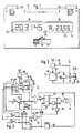
- Fig. 1 eine als Termin- oder Weckeruhr ausgelegte autonome Funkuhr mit digitaler Anzeige,
- Fig. 2 im vereinfachten, einpoligen Blockschaltbild die Gewinnung einer aktuellen Anzeige-Information über die Empfangsgegebenheiten
und - Fig. 3 im vereinfachten-einpoligen Blockschaltbild die von der Stellung eines Betriebsarten-Umschalters abhängige Funktion zweier Tastschalter zur Beeinflussung des Alarmgabe-Zeitpunktes und des Alarmsignales (ohne Berücksichtigung der über die selben Schalter möglichen Zusatzanzeige-Umschaltung zwischen aktuellem Datum und vorgegebenem Alarmgabezeitpunt).
- 1 is an autonomous radio clock with a digital display designed as an appointment or alarm clock,
- Fig. 2 in the simplified, single-pole block diagram, the acquisition of current display information about the reception conditions
and - Fig. 3 in the simplified, single-pole block diagram the function of two pushbuttons depending on the position of an operating mode switch for influencing the alarm signaling time and the alarm signal (without taking into account the additional display switchover between the current date and the given alarm signaling time, which is possible via the same switch).
Die autonome Funkuhr 11 besteht aus einem Funkempfänger 12 und einer Steuerschaltung 13 zur Überprüfung und gegebenenfalls Korrektur der momentanen Zeitanzeige nach Maßgabe der periodisch von einem Zeitnormal-Sender übermittelten aktuellen Zeitinformation 10 sowie zum daran anschließenden intern-zeithaltenden weiteren Betrieb bis zum nächsten Zeitinformations-Empfang, wie etwa in der DE-PS 34 39 638 näher beschrieben. Für die Darbietung der Zeitinformation ist gemäß dem Ausführungsbeispiel nun jedoch keine analoge Zeigeranzeige, sondern eine digitale Anzeige mit einem Display 14 aus gruppierten Digits 15 vorgesehen. Wenigstens ein Anzeigeelement 16, im dargestellten Beispiel bestehend aus zwei Digits 15 zusätzlich zur sonstigen Digitalanzeige auf dem Display 14, dienen der Darbietung von Informationen über aktuelle Empfangsgegebenheiten. Dafür wird ein Zähler 17 von einem Taktgeber 18 (bei dem es sich um die in Zusammenhang mit der Steuerschaltung 13 ausgebildete zeithaltende Schaltung für den autonomen Uhrenbetrieb handeln kann) mit Zählimpulsen beaufschlagt und eine Information proportional zum Zählergebnis über das Anzeigeelement 16 dargeboten. Immer dann, wenn die Steuerschaltung 13 über den Empfänger 12 eine aktuelle Zeitinformation 10 zum Vergleich mit der momentanen Zeitanzeige 19 (und gegebenenfalls zur Korrektur der momentanen Zeitanzeige 19) empfängt, wird der Rücksetzeingang R des Zählers 17 aus der Steuerschaltung 13 zum Rücksetzen in den Zählanfangszustand angesteuert. Das die Empfangsgegebenheiten darbietende Anzeigeelement 16 zeigt einen desto höheren Informationswert an, je länger die letzte Überprüfung der Zeitanzeige 19 zurückliegt, je unsicherer deshalb die Übereinstimmung zwischen der momentanen Zeitanzeige und der tatsächlichen, aktuellen Zeit geworden ist. Wenn als gemäß dem bevorzugten Realisierungsbeispiel die Zählanfangsstellung des Zählers 17 beim Wert NULL liegt, stündlich ein Zähltakt an den Zähler 17 ausgegeben wird und stündlich eine Überprüfung der aktuellen Zeitanzeige 19 mit der über Funk empfangenen Zeitinformation 10 stattfindet, dann wird das zweistellige digitale Anzeigeelement 16 stets auf "00" gehalten. Sollte diese Anzeige dagegen im Stundentakt ansteigen, dann bedeutet das, die Empfangsgegebenheiten am Aufstellungsorte der Funkuhr 11 sind so schlecht, daß schon über die angezeigte Anzahl von Stunden hinweg kein Empfang von dekodierbaren, gültigen Zeitinformationen 10 mehr möglich war und deshalb die momentanen Zeitanzeige 19 entsprechend ungewiß (da lange nicht mehr bestätigt) ist; weshalb die Funkuhr 11 tunlichst in eine andere räumliche Position oder Umgebung verbracht wird, in der die eingebaute Antenne 20 wieder ungestörten Funkempfang ermöglicht, als auswertbare Zeitinformationen 10 liefert.The
Zusätzlich kann vorgesehen sein, mittels des Anzeigeelementes 16 zu signalisieren, wenn die Funkuhr 11 auf Empfang geschaltet ist (um eine aktuelle Funk-Zeitinformation für die Kontrolle der momentanen Zeitanzeige 19 zu übernehmen). Das erfolgt beispielsweise mittels einer Modulatorschaltung 21, die aus dem Empfänger 12 im Sekundentakt der Zeitinformations-Kodierung angesteuert wird und dadurch zum Sekunden-Blinken wenigstens eines der Digits 15 des Anzeigeelementes 16 führt.In addition, it can be provided to indicate by means of the
Wenn das Display 14 außer über die Zeitanzeige 19 auch über eine Zusatzanzeige 22 verfügt, ist das den Funkempfangsgegebenheiten zugeordnete Anzeigeelement 16 zweckmäßigerweise in der Mitte zwischen beiden Anzeigen 19-22 und damit in der Mitte des Display 14, in der Größenordnung und sonstigen Auffälligkeit untergeordnet, angeordnet, wie in Fig. 1 berücksichtigt. Die Zusatzanzeige 22 kann eine Datumsinformation darstellen, wie sie ebenfalls über Funk übermittelt wird und bei autonomen Uhrenbetrieb aus dem Zeitablauf ableitbar ist, dargestellt beispielsweise über zwei Paare von Ziffern-Digits 15 mit je einem Punkt 23 dahinter. Stattdessen oder alternativ kann die Zusatzanzeige 22 aber auch eine Alarmzeitanzeige sein, bestehend aus den beiden Ziffernpaaren-Digits 15 mit nun nur einem dazwischen angeordneten Dezimalpunkt 23 und vorangestellten Buchstabendigits 15 "AL" (vgl. Fig. 1). Falls die Funkuhr 11 also als Termin- oder Weckeruhr ausgestattet ist, ergibt die AL-Anzeige 22 somit den manuell vorgegebenen Zeitpunkt an, zu dem ein Alarmsignal 24 ausgelöst werden wird.If the
Während die Einstellung der Zeitanzeige 19 und der Datums-Zusatzanzeige 22 bei Empfang einer Zeitinformation 10 automatisch über die Steuerschaltung 13 erfolgt, ist für die Vorgabe des Alarmzeitpunktes eine manuelle Operation erforderlich. Hierfür wird ein Betriebsarten-Umschalter S3 in die SET-Stellung gebracht, woraufhin über Tastschalter S1 bzw. S2 schrittweise das die Stunden bzw. das die Minuten anzeigende Digit-Paar verändert, beispielsweise im Rhythmus der manuellen Schalterbetätigung weitergeschaltet werden kann.While the setting of the time display 19 and the
Wenn der Betriebsarten-Umschalter S3 nicht in der SET-Stellung ist, bewirkt dagegen die Betätigung eines beliebigen der Tastschalter S1 und S2 eine Umschaltung der Zusatzanzeige 22 zwischen Alarmzeitvorgabe (Fig. 1) und Datum; wobei die gerade gegebene Anzeige 22 bis zur nächsten Tastschalter-Betätigung stehen bleiben kann, oder aber schaltungstechnisch ein Rückkippen in eine bevorzugte Anzeige 22 vorgesehen sein kann.If the operating mode switch S3 is not in the SET position, on the other hand, actuation of any of the pushbuttons S1 and S2 causes the
In der ON-Stellung der Betriebsarten-Umschalters S3 wird eine Koinzidenzstufe 25 aktiviert, die bei Übereinstimmung der vorgegebenen Alarmzeit mit der tatsächlich erreichten Zeit über ein Koinzidenzsignal 26 eine bistabile Stufe 27 zur Ansteuerung eines Alarmgebers 28 (beispielsweise eines Piezoelektrischen Wandlers) für die Abstrahlung des Alarmsignales 24 setzt.In the ON position of the operating mode switch S3, a
Wenn nun ein beliebiger aber nur einer der Tastschalter S1 oder S2 betätigt wird, wird über ein Exklusiv-ODER-Gatter 29 einerseits die Kippstufe 27 zurückgesetzt und andererseits eine monostabile Kippstufe 30 gestartet, um nach einer gewissen (schaltungstechnisch vorgegebenen) Pausenzeit die bistabile Stufe 27 wieder auf Alarmgabe zu setzen (SNOOZE-Weckwiederholungsfunktion). Wenn dagegen beide Tastschalter S1 und S2 gleichzeitig (zeitlich überlappend) betätigt werden, spricht nicht das Exklusiv-ODER-Gatter 29, sondern ein den Schaltern S1, S2 nachgeschaltetes UND-Gatter 31 an, über das die Signalgabe-Stufe 27 zurückgesetzt wird. Wenn momentan kein Alarmsignal 24 abgestrahlt wurde, wird über eine Kippstufe 32 wenigstens eine zeitlich sehr kurze (gegebenenfalls in Frequenz oder Modulation eigenartige) Signalgabe ausgelöst, die als akustische Quittung für die überlappende Betätiguung der beiden Tastschalter S1-S2 dient. Diese "AL STOP"-Betätigung bewirkt im übrigen, daß erst dann erneut ein Alarmsignal 24 abgestrahlt wird, wenn (nach 24 Stunden) erneut eine zeitliche Koinzidenz zwischen der momentanen Vorgabe-Anzeige 22 und der aktuellen Zeitanzeige 19 erreicht ist.If now any but only one of the pushbuttons S1 or S2 is actuated, on the one hand the flip-flop 27 is reset via an exclusive-
Eine in der gesetzten Stellung der Alarmgabe-Stufe 27 gestartete Zeitschaltung 33 dient der automatischen Beendigung der Abgabe des Alarmsignales 24 nach einer gewissen Zeitspanne, wenn keine manuelle Unterbrechung bzw. Beendigung über die Tastschalter S1, S2 erfolgte; um eine andauernde Ruhestörung, bzw. eine unnötige Belastung der Energiequelle (etwa einer Batterie) für den Betrieb der Funkuhr 11, zu vermeiden.A
In der OFF-Stellung des Betriebsarten-Umschalters S3 erfolgt zweckmäßigerweise eine starre Festlegung der bistabilen Alarmgabe-Stufe 27 in der rückgesetzten Stellung, so daß eine Alarmgabe-Auslösung über die Koinzidenzstufe 25 schon aus diesem Grunde nicht erfolgen kann.In the OFF position of the operating mode switch S3, the bistable alarm stage 27 is expediently fixed in the reset position, so that an alarm cannot be triggered via the
Durch die in Fig. 3 gezeigte Gatterschaltung ist im übrigen sichergestellt, daß nur in der SET-Stellung des Betriebsarten-Umschalters S3 eine Betätigung eines (und momentan jeweils nur eines) der Tastschalter S1, S2 zur Modifikation der Alarmzeit-Vorgabe an die Koinzidenzstufe 25 führt; während in den beiden anderen Stellungen (ON oder OFF) ein Signal 34 erzeugt wird, das die Information-Umschaltung der Zusatzanzeige 22 (Datum -- Alarmzeitpunkt) bei Betätigung eines beliebigen der Tastschalter S1, S2 freigibt; was jedoch im Interesse der Übersichtlichkeit in Fig. 3 nicht näher schaltungstechnisch ausgeführt ist.The gate circuit shown in FIG. 3 also ensures that only one (and currently only one) of the pushbuttons S1, S2 for modifying the alarm time specification to the
Ebenfalls im gezeichneten Schaltungsbeispiel nicht berücksichtigt ist, daß die dargestellte Gatterschaltung sowie die Wirkungen der monostabilen und bistabilen Kippstufen zweckmäßigerweise nicht durch diskreten Schaltungsaufbau realisiert werden, sondern durch zusätzliche Funktionen eines zentralen Prozessors wahrgenommen werden, der ohnehin in der Steuerschaltung 13 für die periodische Einschaltung des Empfängers 12, für die Dekodierung der über Funk empfangenen absoluten Zeitinformation 10 und erforderlichenfalls für die Korrektur der Zeit- und Datumsanzeigen 19, 22 enthalten ist.Also not taken into account in the illustrated circuit example that the gate circuit shown and the effects of the monostable and bistable flip-flops are advantageously not realized by a discrete circuit structure, but are perceived by additional functions of a central processor, which is in any case in the
Claims (11)
dadurch gekennzeichnet,
daß ein von einem Zähler (17) gesteuertes Anzeigeelement (16) vorgesehen ist, der von einem Taktgeber (18) hochgezählt und bei Dekodierung einer gültigen, über Funk empfangenen Zeitinformation (10) rückgesetzt wird.1. Autonomous radio clock (11) with information about the reception conditions
characterized,
that a display element (16) controlled by a counter (17) is provided, which is counted up by a clock generator (18) and is reset when a valid time information (10) received by radio is decoded.
dadurch gekennzeichnet,
daß das Anzeigeelement (16) aus gesonderten Digits (15) in einem Display (14) beseht.2. radio clock according to claim 1,
characterized,
that the display element (16) consists of separate digits (15) in a display (14).
dadurch gekennzeichnet,
daß der Taktgeber (18) auch die periodische Einschaltung des Funkempfängers (12) steuert.3. Radio clock according to claim 1 or 2,
characterized,
that the clock (18) also controls the periodic activation of the radio receiver (12).
dadurch gekennzeichnet,
daß die Ansteuerung des Anzeigeelementes (16) über eine Modulationsschaltung (21) im vom eingeschalteten Funkempfänger (12) gelieferten Kodier-Takt der Zeitinformation (10) erfolgt.4. Radio clock according to one of the preceding claims,
characterized,
that the control of the display element (16) takes place via a modulation circuit (21) in the coding cycle of the time information (10) supplied by the switched-on radio receiver (12).
dadurch gekennzeichnet,
daß das Anzeigeelement (16) in einem Digital-Display (14) zwischen der Zeitanzeige (19) und einer Zusatzanzeige (22) angeordnet ist.5. radio clock according to claim 4,
characterized,
that the display element (16) is arranged in a digital display (14) between the time display (19) and an additional display (22).
dadurch gekennzeichnet,
daß sie mit einem über eine Koinzidenzstufe (25) ansteuerbaren Alarmgeber (28) ausgestattet ist.6. Radio clock according to one of the preceding claims,
characterized,
that it is equipped with an alarm transmitter (28) which can be controlled via a coincidence stage (25).
dadurch gekennzeichnet,
daß der Alarmgeber (28) während der Korrektur der Zeitanzeige (19) nach Maßgabe der über Funk empfangenen Zeitinformation (10) gesperrt ist.7. radio clock according to claim 6,
characterized,
that the alarm transmitter (28) is blocked during the correction of the time display (19) in accordance with the time information (10) received by radio.
dadurch gekennzeichnet,
daß die Zusatzanzeige (22) manuell zwischen Anzeige eines manuell veränderbaren Alarmzeitpunktes und Anzeige des in der Funk-Zeitinformation (10) enthaltenen Datums umschaltbar ist.8. Radio clock according to claim 6 or 7,
characterized,
that the additional display (22) can be switched manually between displaying a manually changeable alarm time and displaying the date contained in the radio time information (10).
dadurch gekennzeichnet,
daß sie mit einem Betriebsarten-Umschalter (S3) und mit zwei manuell betätigbaren Schaltern (S1, S2) ausgestattet ist, von denen in der SET-Stellung des Umschalters (S3) der eine der Veränderung der Signalgabe-Stundenanzeige und der andere der Veränderung der Signalgabe-Minutenanzeige zugeordnet ist, während in der ALARM-(ON-)Stellung jeder der beiden Schalter (S1,S2) der vorübergehenden Unterbrechung (SNOOZE) des Alarmsignales (24) und zeitlich überlappende Betätigung beider Schalter (S1,S2) der Abschaltung des Alarmsignales (24) zugeordnet ist.9. Radio clock in particular according to one of claims 6 to 8,
characterized,
that it is equipped with an operating mode switch (S3) and with two manually operated switches (S1, S2), one of which in the SET position of the switch (S3) changes the signaling hour display and the other changes the Signaling minute display is assigned, while in the ALARM (ON) position each of the two switches (S1, S2) the temporary interruption (SNOOZE) of the alarm signal (24) and overlapping actuation of both switches (S1, S2) the shutdown of the Alarm signals (24) is assigned.
dadurch gekennzeichnet,
daß ein Quittiersignal ausgelöst wird, wenn durch zeitlich überlappende Betätigung der Schalter (S1,S2) die Ansteuerung des Signalgebers (28) blockiert wird (AL STOP), mit Wieder-Aufhebung der Blockage bei nächstfolgend erreichter Koinzidenz zwischen der Zeitanzeige (19) und dem vorgegebenen Alarmgabe-Zeitpunkt.11. Radio clock according to one of claims 6 to 10,
characterized,
that an acknowledgment signal is triggered when the actuation of the signal generator (28) is blocked (AL STOP) by overlapping actuation of the switches (S1, S2), with the blockage being removed when the coincidence between the time display (19) and the next one is reached predefined alarm time.
Applications Claiming Priority (2)
| Application Number | Priority Date | Filing Date | Title |
|---|---|---|---|
| DE3731956 | 1987-09-23 | ||
| DE19873731956 DE3731956A1 (en) | 1987-09-23 | 1987-09-23 | AUTONOMOUS RADIO WATCH |
Publications (3)
| Publication Number | Publication Date |
|---|---|
| EP0308881A2 true EP0308881A2 (en) | 1989-03-29 |
| EP0308881A3 EP0308881A3 (en) | 1991-03-13 |
| EP0308881B1 EP0308881B1 (en) | 1993-12-01 |
Family
ID=6336636
Family Applications (1)
| Application Number | Title | Priority Date | Filing Date |
|---|---|---|---|
| EP88115451A Expired - Lifetime EP0308881B1 (en) | 1987-09-23 | 1988-09-21 | Radio-controlled watch |
Country Status (3)
| Country | Link |
|---|---|
| US (1) | US5083123A (en) |
| EP (1) | EP0308881B1 (en) |
| DE (3) | DE3731956A1 (en) |
Cited By (6)
| Publication number | Priority date | Publication date | Assignee | Title |
|---|---|---|---|---|
| EP0439725A2 (en) * | 1990-01-31 | 1991-08-07 | Junghans Uhren Gmbh | Autonomous radio-controlled clock |
| EP0455183A2 (en) * | 1990-05-04 | 1991-11-06 | Junghans Uhren Gmbh | Autonomous radio-controlled clock |
| EP0504690A1 (en) * | 1991-03-16 | 1992-09-23 | DIEHL GMBH & CO. | Laser-aided weapon effect simulator |
| US5408445A (en) * | 1991-08-23 | 1995-04-18 | Junghans Uhren Gmbh | Radio timepiece |
| EP0656572A1 (en) * | 1993-12-01 | 1995-06-07 | Seiko Instruments Inc. | Radio wave-corrected timepiece |
| EP0657794A2 (en) * | 1993-12-07 | 1995-06-14 | Casio Computer Company Limited | Time date receiving apparatus |
Families Citing this family (13)
| Publication number | Priority date | Publication date | Assignee | Title |
|---|---|---|---|---|
| DE9010813U1 (en) * | 1990-07-20 | 1991-11-14 | Junghans Uhren Gmbh, 7230 Schramberg, De | |
| DE4230531C1 (en) * | 1992-09-12 | 1993-11-18 | Braun Ag | Radio clock |
| DE4233126A1 (en) * | 1992-10-02 | 1994-04-07 | Telefunken Microelectron | Procedure for the operation of a radio clock and radio clock for use in an environment subject to interference |
| DE4416869A1 (en) * | 1994-05-13 | 1995-11-16 | Opel Adam Ag | Control device for a clock to be synchronized by radio signals |
| JPH10341466A (en) * | 1997-06-10 | 1998-12-22 | Nec Shizuoka Ltd | Selective call radio receiver |
| US7230884B2 (en) * | 2003-01-03 | 2007-06-12 | The Sapling Company, Inc. | Clock diagnostics |
| US6958953B2 (en) * | 2003-05-13 | 2005-10-25 | International Business Machines Corporation | Real time clock circuit having an internal clock generator |
| US7068569B2 (en) * | 2003-08-08 | 2006-06-27 | John Dutkiewicz | Apparatus and method for displaying time and randomly-selected text information |
| JP3876887B2 (en) * | 2004-02-04 | 2007-02-07 | カシオ計算機株式会社 | Radio receiver, radio receiver, radio clock, and repeater |
| US20050250551A1 (en) * | 2004-05-10 | 2005-11-10 | Nokia Corporation | Notification about an event |
| US20050259722A1 (en) * | 2004-05-21 | 2005-11-24 | Reginald Vanlonden | Wireless clock system |
| KR100782513B1 (en) * | 2006-03-14 | 2007-12-05 | 삼성전자주식회사 | Mobile Communication Terminal and the Method for managing Alarm of receiving Digital Broadcast data |
| JP2008170230A (en) * | 2007-01-10 | 2008-07-24 | Seiko Epson Corp | Time correction apparatus, timer device equipped with the same, and time correction method |
Citations (3)
| Publication number | Priority date | Publication date | Assignee | Title |
|---|---|---|---|---|
| GB1596628A (en) * | 1978-01-23 | 1981-08-26 | Plessey Co Ltd Heriter F A | Indicating devices |
| DE3015312A1 (en) * | 1980-04-21 | 1981-10-22 | Wolfgang Dr.-Ing. 6101 Groß-Bieberau Hilberg | Display of signal quality received by radio controlled clock - compares second timing impulses with reference level to drive visual indicator |
| FR2579335A1 (en) * | 1985-03-23 | 1986-09-26 | Junghans Uhren Gmbh | Radio clock allowing addition of auxiliary items |
Family Cites Families (9)
| Publication number | Priority date | Publication date | Assignee | Title |
|---|---|---|---|---|
| US3795099A (en) * | 1971-02-18 | 1974-03-05 | Y Tsuruishi | Electronic timepiece having a chronograph mechanism |
| DE2425254C3 (en) * | 1973-05-28 | 1980-11-20 | Citizen Watch Co., Ltd., Tokio | Portable electronic watch |
| JPS5357876A (en) * | 1976-11-05 | 1978-05-25 | Citizen Watch Co Ltd | Watch with battery life warning display |
| US4255803A (en) * | 1977-07-06 | 1981-03-10 | Citizen Watch Company Limited | Electronic timepiece equipped with alarm function |
| US4301524A (en) * | 1978-01-04 | 1981-11-17 | Fairchild Camera And Instrument Corp. | Programmable alarm clock |
| JPS5590883A (en) * | 1978-12-29 | 1980-07-09 | Osawa Shokai:Kk | Clock |
| JPS5950950B2 (en) * | 1979-04-13 | 1984-12-11 | セイコーインスツルメンツ株式会社 | electronic clock with radio |
| JPS5679281A (en) * | 1979-12-03 | 1981-06-29 | Norio Iwasaki | Time-correcting apparatus of timepiece by time signal tone |
| DE3439638C1 (en) * | 1984-10-30 | 1986-05-15 | Gebrüder Junghans GmbH, 7230 Schramberg | Autonomous radio clock |
-
1987
- 1987-09-23 DE DE19873731956 patent/DE3731956A1/en not_active Withdrawn
- 1987-09-23 DE DE8717549U patent/DE8717549U1/de not_active Expired
-
1988
- 1988-09-21 DE DE88115451T patent/DE3885990D1/en not_active Expired - Fee Related
- 1988-09-21 EP EP88115451A patent/EP0308881B1/en not_active Expired - Lifetime
-
1990
- 1990-10-18 US US07/598,830 patent/US5083123A/en not_active Expired - Fee Related
Patent Citations (3)
| Publication number | Priority date | Publication date | Assignee | Title |
|---|---|---|---|---|
| GB1596628A (en) * | 1978-01-23 | 1981-08-26 | Plessey Co Ltd Heriter F A | Indicating devices |
| DE3015312A1 (en) * | 1980-04-21 | 1981-10-22 | Wolfgang Dr.-Ing. 6101 Groß-Bieberau Hilberg | Display of signal quality received by radio controlled clock - compares second timing impulses with reference level to drive visual indicator |
| FR2579335A1 (en) * | 1985-03-23 | 1986-09-26 | Junghans Uhren Gmbh | Radio clock allowing addition of auxiliary items |
Cited By (12)
| Publication number | Priority date | Publication date | Assignee | Title |
|---|---|---|---|---|
| EP0439725A2 (en) * | 1990-01-31 | 1991-08-07 | Junghans Uhren Gmbh | Autonomous radio-controlled clock |
| EP0439725A3 (en) * | 1990-01-31 | 1992-01-15 | Junghans Uhren Gmbh | Autonomous radio clock |
| EP0455183A2 (en) * | 1990-05-04 | 1991-11-06 | Junghans Uhren Gmbh | Autonomous radio-controlled clock |
| EP0455183A3 (en) * | 1990-05-04 | 1992-01-15 | Junghans Uhren Gmbh | Autonomous radio clock |
| EP0504690A1 (en) * | 1991-03-16 | 1992-09-23 | DIEHL GMBH & CO. | Laser-aided weapon effect simulator |
| US5408445A (en) * | 1991-08-23 | 1995-04-18 | Junghans Uhren Gmbh | Radio timepiece |
| DE4219257C2 (en) * | 1991-08-23 | 2003-07-10 | Junghans Uhren Gmbh | Autonomous radio clock with time zone switchover |
| EP0656572A1 (en) * | 1993-12-01 | 1995-06-07 | Seiko Instruments Inc. | Radio wave-corrected timepiece |
| US5621703A (en) * | 1993-12-01 | 1997-04-15 | Seiko Instruments Inc. | Radio wave-corrected timepiece |
| EP0657794A2 (en) * | 1993-12-07 | 1995-06-14 | Casio Computer Company Limited | Time date receiving apparatus |
| EP0657794A3 (en) * | 1993-12-07 | 1995-12-13 | Casio Computer Co Ltd | Time date receiving apparatus. |
| US5537101A (en) * | 1993-12-07 | 1996-07-16 | Casio Computer Co., Ltd. | Time data receiving apparatus |
Also Published As
| Publication number | Publication date |
|---|---|
| DE3731956A1 (en) | 1989-04-06 |
| EP0308881B1 (en) | 1993-12-01 |
| US5083123A (en) | 1992-01-21 |
| EP0308881A3 (en) | 1991-03-13 |
| DE3885990D1 (en) | 1994-01-13 |
| DE8717549U1 (en) | 1989-02-02 |
Similar Documents
| Publication | Publication Date | Title |
|---|---|---|
| EP0308881B1 (en) | Radio-controlled watch | |
| EP0180155B1 (en) | Radio-controlled watch | |
| DE69735089T2 (en) | INJECTION DEVICE WITH ELECTRONIC DISPLAY OF SET DOSES | |
| EP0455183B1 (en) | Autonomous radio-controlled clock | |
| DE2840258C3 (en) | Electronic timing device | |
| EP0529390B1 (en) | Means for detecting gear position and means for correction | |
| EP0042913B1 (en) | Process for the automatic setting of radio clocks aided by time signals | |
| EP0374745B1 (en) | Autonomous radio-controlled clock | |
| EP0372432B1 (en) | Autonomous radio clock | |
| DE2521698C3 (en) | Electronic clocks, in particular electronic wristwatches | |
| DE2643250A1 (en) | Slave clock receiving coded time signal - has error detection circuit and optical display | |
| EP0439725B1 (en) | Autonomous radio-controlled clock | |
| DE3510636C2 (en) | Autonomous radio clock with time signal generator | |
| EP0308880B1 (en) | Autonomous radio clock | |
| DE10006660B4 (en) | Time information repeater and time information control system | |
| EP0185160A2 (en) | Radio-controlled time piece | |
| DE4219257C2 (en) | Autonomous radio clock with time zone switchover | |
| DE2228275B2 (en) | ELECTRONIC DIGITAL CLOCK | |
| DE3002723A1 (en) | ELECTRONIC CLOCK | |
| DE2539224B2 (en) | Procedure for automatically correcting the time display of a watch and clock to perform this procedure | |
| DE19543590C1 (en) | Radio clock | |
| EP0204851A2 (en) | Electric watch | |
| EP0423576B1 (en) | Electromechanical schedule-clock | |
| EP0553722A2 (en) | Small autonomous radio timepiece with analogue display, in particular wristwatch radio | |
| EP0664496B1 (en) | Clock with switchable time display, in particular radio alarm clock with digital display of the alarm time |
Legal Events
| Date | Code | Title | Description |
|---|---|---|---|
| PUAI | Public reference made under article 153(3) epc to a published international application that has entered the european phase |
Free format text: ORIGINAL CODE: 0009012 |
|
| AK | Designated contracting states |
Kind code of ref document: A2 Designated state(s): CH DE FR GB IT LI |
|
| PUAL | Search report despatched |
Free format text: ORIGINAL CODE: 0009013 |
|
| AK | Designated contracting states |
Kind code of ref document: A3 Designated state(s): CH DE FR GB IT LI |
|
| 17P | Request for examination filed |
Effective date: 19910207 |
|
| 17Q | First examination report despatched |
Effective date: 19911212 |
|
| GRAA | (expected) grant |
Free format text: ORIGINAL CODE: 0009210 |
|
| AK | Designated contracting states |
Kind code of ref document: B1 Designated state(s): CH DE FR GB IT LI |
|
| REF | Corresponds to: |
Ref document number: 3885990 Country of ref document: DE Date of ref document: 19940113 |
|
| GBT | Gb: translation of ep patent filed (gb section 77(6)(a)/1977) |
Effective date: 19940111 |
|
| ITF | It: translation for a ep patent filed |
Owner name: STUDIO JAUMANN |
|
| ET | Fr: translation filed | ||
| PGFP | Annual fee paid to national office [announced via postgrant information from national office to epo] |
Ref country code: CH Payment date: 19940812 Year of fee payment: 7 |
|
| PGFP | Annual fee paid to national office [announced via postgrant information from national office to epo] |
Ref country code: FR Payment date: 19940829 Year of fee payment: 7 |
|
| PGFP | Annual fee paid to national office [announced via postgrant information from national office to epo] |
Ref country code: GB Payment date: 19940915 Year of fee payment: 7 |
|
| PLBE | No opposition filed within time limit |
Free format text: ORIGINAL CODE: 0009261 |
|
| STAA | Information on the status of an ep patent application or granted ep patent |
Free format text: STATUS: NO OPPOSITION FILED WITHIN TIME LIMIT |
|
| 26N | No opposition filed | ||
| PG25 | Lapsed in a contracting state [announced via postgrant information from national office to epo] |
Ref country code: GB Effective date: 19950921 |
|
| PG25 | Lapsed in a contracting state [announced via postgrant information from national office to epo] |
Ref country code: LI Effective date: 19950930 Ref country code: CH Effective date: 19950930 |
|
| GBPC | Gb: european patent ceased through non-payment of renewal fee |
Effective date: 19950921 |
|
| REG | Reference to a national code |
Ref country code: CH Ref legal event code: PL |
|
| PG25 | Lapsed in a contracting state [announced via postgrant information from national office to epo] |
Ref country code: FR Effective date: 19960531 |
|
| REG | Reference to a national code |
Ref country code: FR Ref legal event code: ST |
|
| PGFP | Annual fee paid to national office [announced via postgrant information from national office to epo] |
Ref country code: DE Payment date: 20041122 Year of fee payment: 17 |
|
| PG25 | Lapsed in a contracting state [announced via postgrant information from national office to epo] |
Ref country code: IT Free format text: LAPSE BECAUSE OF NON-PAYMENT OF DUE FEES;WARNING: LAPSES OF ITALIAN PATENTS WITH EFFECTIVE DATE BEFORE 2007 MAY HAVE OCCURRED AT ANY TIME BEFORE 2007. THE CORRECT EFFECTIVE DATE MAY BE DIFFERENT FROM THE ONE RECORDED. Effective date: 20050921 |
|
| PG25 | Lapsed in a contracting state [announced via postgrant information from national office to epo] |
Ref country code: DE Free format text: LAPSE BECAUSE OF NON-PAYMENT OF DUE FEES Effective date: 20060401 |