EP0312939A2 - High temperature storage battery - Google Patents
High temperature storage battery Download PDFInfo
- Publication number
- EP0312939A2 EP0312939A2 EP19880117184 EP88117184A EP0312939A2 EP 0312939 A2 EP0312939 A2 EP 0312939A2 EP 19880117184 EP19880117184 EP 19880117184 EP 88117184 A EP88117184 A EP 88117184A EP 0312939 A2 EP0312939 A2 EP 0312939A2
- Authority
- EP
- European Patent Office
- Prior art keywords
- cooling medium
- cells
- distributor plate
- free space
- temperature storage
- Prior art date
- Legal status (The legal status is an assumption and is not a legal conclusion. Google has not performed a legal analysis and makes no representation as to the accuracy of the status listed.)
- Ceased
Links
Images

Classifications
-
- H—ELECTRICITY
- H01—ELECTRIC ELEMENTS
- H01M—PROCESSES OR MEANS, e.g. BATTERIES, FOR THE DIRECT CONVERSION OF CHEMICAL ENERGY INTO ELECTRICAL ENERGY
- H01M10/00—Secondary cells; Manufacture thereof
- H01M10/36—Accumulators not provided for in groups H01M10/05-H01M10/34
- H01M10/39—Accumulators not provided for in groups H01M10/05-H01M10/34 working at high temperature
-
- H—ELECTRICITY
- H01—ELECTRIC ELEMENTS
- H01M—PROCESSES OR MEANS, e.g. BATTERIES, FOR THE DIRECT CONVERSION OF CHEMICAL ENERGY INTO ELECTRICAL ENERGY
- H01M10/00—Secondary cells; Manufacture thereof
- H01M10/60—Heating or cooling; Temperature control
- H01M10/61—Types of temperature control
- H01M10/613—Cooling or keeping cold
-
- H—ELECTRICITY
- H01—ELECTRIC ELEMENTS
- H01M—PROCESSES OR MEANS, e.g. BATTERIES, FOR THE DIRECT CONVERSION OF CHEMICAL ENERGY INTO ELECTRICAL ENERGY
- H01M10/00—Secondary cells; Manufacture thereof
- H01M10/60—Heating or cooling; Temperature control
- H01M10/64—Heating or cooling; Temperature control characterised by the shape of the cells
- H01M10/643—Cylindrical cells
-
- H—ELECTRICITY
- H01—ELECTRIC ELEMENTS
- H01M—PROCESSES OR MEANS, e.g. BATTERIES, FOR THE DIRECT CONVERSION OF CHEMICAL ENERGY INTO ELECTRICAL ENERGY
- H01M10/00—Secondary cells; Manufacture thereof
- H01M10/60—Heating or cooling; Temperature control
- H01M10/65—Means for temperature control structurally associated with the cells
- H01M10/656—Means for temperature control structurally associated with the cells characterised by the type of heat-exchange fluid
- H01M10/6561—Gases
- H01M10/6563—Gases with forced flow, e.g. by blowers
-
- H—ELECTRICITY
- H01—ELECTRIC ELEMENTS
- H01M—PROCESSES OR MEANS, e.g. BATTERIES, FOR THE DIRECT CONVERSION OF CHEMICAL ENERGY INTO ELECTRICAL ENERGY
- H01M10/00—Secondary cells; Manufacture thereof
- H01M10/60—Heating or cooling; Temperature control
- H01M10/65—Means for temperature control structurally associated with the cells
- H01M10/656—Means for temperature control structurally associated with the cells characterised by the type of heat-exchange fluid
- H01M10/6561—Gases
- H01M10/6566—Means within the gas flow to guide the flow around one or more cells, e.g. manifolds, baffles or other barriers
-
- H—ELECTRICITY
- H01—ELECTRIC ELEMENTS
- H01M—PROCESSES OR MEANS, e.g. BATTERIES, FOR THE DIRECT CONVERSION OF CHEMICAL ENERGY INTO ELECTRICAL ENERGY
- H01M10/00—Secondary cells; Manufacture thereof
- H01M10/60—Heating or cooling; Temperature control
- H01M10/65—Means for temperature control structurally associated with the cells
- H01M10/658—Means for temperature control structurally associated with the cells by thermal insulation or shielding
-
- Y—GENERAL TAGGING OF NEW TECHNOLOGICAL DEVELOPMENTS; GENERAL TAGGING OF CROSS-SECTIONAL TECHNOLOGIES SPANNING OVER SEVERAL SECTIONS OF THE IPC; TECHNICAL SUBJECTS COVERED BY FORMER USPC CROSS-REFERENCE ART COLLECTIONS [XRACs] AND DIGESTS
- Y02—TECHNOLOGIES OR APPLICATIONS FOR MITIGATION OR ADAPTATION AGAINST CLIMATE CHANGE
- Y02E—REDUCTION OF GREENHOUSE GAS [GHG] EMISSIONS, RELATED TO ENERGY GENERATION, TRANSMISSION OR DISTRIBUTION
- Y02E60/00—Enabling technologies; Technologies with a potential or indirect contribution to GHG emissions mitigation
- Y02E60/10—Energy storage using batteries
Definitions
- the invention relates to a high-temperature storage battery according to the preamble of claim 1.
- a high-temperature storage battery is known from DE-OS 32 47 969. It is a battery with several electrochemical cells for storing electrical energy.
- the battery works at elevated temperature, in the case of a sodium / sulfur battery, e.g. in the temperature range from about 300 ° to 350 ° C.
- the solution according to the invention has the advantage that in the free space - above the distributor plate above the cells or in another variant below the distributor plate below the cells - a quasi-flat inflow profile transverse to the main flow direction through the distributor plate is achieved with the aid of the proposed prechamber.
- This profile is achieved regardless of the speed of the coolant flow at the inlet opening of the battery.
- Such a flow profile does not occur without the prechamber according to the invention, because the inlet opening must be made as small as possible with a view to minimizing heat losses and the distributor plate in the free space above or below the cells has a relatively large area.
- the battery 1 shows a section of a high-temperature storage battery 1.
- the battery 1 contains an arrangement of several electrochemical cells 2 and is surrounded by thermal insulation 3 as a housing.
- the thermal insulation 3 is broken at some points for the passage of the battery poles, measuring lines and connections for cooling.
- Such implementations must be kept as small as possible and their number minimized. Therefore, for example, preferably only one inlet opening 4 for a cooling medium, for example air, is to be provided, the cross section of the inlet opening 4 should be small.
- a prechamber 7 in which the cooling medium builds up and via several throttle points 8, for example nozzles or holes in a sheet metal cover 9, into the free space 5 flows.
- the pre-chamber 7 consists of a channel 10 lying transversely to the inlet opening or openings 4, which merges into a curved shaft 11 and is closed off by the perforated diaphragm 9 provided with throttling points 8. It is essential that the cooling medium flows into the free space 5 with the same volume flow at all throttling points 8.
- the path of the cooling medium from the inlet opening 4 through the prechamber 7 and the throttling points 8 into the free space 5 and from there through openings or holes 12 in the distributor plate 6 into spaces between the cells 2 is indicated by arrows.
- the cooling medium absorbs the thermal power loss of the neighboring cells and reaches an outlet opening, also not shown, via a collecting channel, not shown.
- the principle of operation shown can be applied several times by means of series and / or parallel arrangements.
- the configurations proposed in the document DE-OS 32 47 969 can also be used in connection with the present invention.
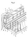
- the distributor plate 6 can also be arranged below the cells 2.
- Such an embodiment variant is shown in FIG. 2. There, the distributor plate 6 covers the top of the free space 5 and through the holes 12 in the distributor plate 6, the cooling medium flows upwards into spaces between the cells 2.
Landscapes
- Engineering & Computer Science (AREA)
- Manufacturing & Machinery (AREA)
- Chemical & Material Sciences (AREA)
- Chemical Kinetics & Catalysis (AREA)
- Electrochemistry (AREA)
- General Chemical & Material Sciences (AREA)
- Secondary Cells (AREA)
- Battery Mounting, Suspending (AREA)
Abstract
Um in Hochtemperaturspeicherbatterien ein Kühlmedium, z.B. Luft gleichmäßig auf Zwischenräume zwischen elektrochemischen Zellen zu verteilen, wurde bereits vorgeschlagen, oberhalb von Zellengruppen einen Freiraum vorzusehen, aus dem das Kühlmedium vorzugsweise über eine Verteilerplatte mit Löchern zu den Zellen geführt wird. Der Erfindung liegt die Aufgabe zugrunde, die Verteilung des Kühlmediums noch weiter zu verbessern. Um ein gleichmäßiges, quasi ebenes Anströmungsprofil für das Kühlmedium über der Verteilerplatte (6) zu erreichen, wird vorgeschlagen, eine Vorkammer (7) vorzusehen, in die das Kühlmedium über mindestens eine Eintrittsöffnung (4) gelangt und von dort über mehrere Drosselstellen (8) in einen Freiraum (5) und von dort durch Löcher (12) der Verteilerplatte (6) zu den Zellen (2) strömt. Die Erfindung kann z.B. bei Natrium/Schwefel-Batterien angewendet werden.In order to store a cooling medium in high-temperature storage batteries, e.g. Distributing air evenly between the spaces between electrochemical cells has already been proposed to provide a space above cell groups from which the cooling medium is preferably led to the cells via a distributor plate with holes. The invention has for its object to further improve the distribution of the cooling medium. In order to achieve a uniform, quasi-flat flow profile for the cooling medium above the distributor plate (6), it is proposed to provide a prechamber (7) into which the cooling medium enters via at least one inlet opening (4) and from there via a plurality of throttling points (8) flows into a free space (5) and from there through holes (12) of the distributor plate (6) to the cells (2). The invention can e.g. be used with sodium / sulfur batteries.
Description
Die Erfindung bezieht sich auf eine Hochtemperaturspeicherbatterie nach dem Oberbegriff des Anspruchs 1. Eine solche Batterie ist aus der DE-OS 32 47 969 bekannt. Dabei handelt es sich um eine Batterie mit mehreren elektrochemischen Zellen zur Speicherung elektrischer Energie. Die Batterie arbeitet bei erhöhter Temperatur, im Falle einer Natrium/Schwefel-Batterie, z.B. im Temperaturbereich von etwa 300° bis 350°C.The invention relates to a high-temperature storage battery according to the preamble of
Um diese Temperatur aufrechterhalten zu können, ist eine hochwirksame thermische Isolierung vorgesehen. Wärmeverluste während Ruhephasen können damit gering gehalten werden. Im Lade- oder Entladebetrieb wird dagegen aufgrund des Batteriewirkungsgrades Wärme erzeugt, die zu einer Erhöhung der Zellentemperatur führt. Wenn eine obere Zellentemperatur erreicht ist, muß mit Hilfe einer Kühleinrichtung Wärme abgeführt werden.In order to be able to maintain this temperature, highly effective thermal insulation is provided. Heat losses during periods of rest can thus be kept low. In contrast, in charging or discharging mode, heat is generated due to the battery efficiency, which leads to an increase in the cell temperature. When an upper cell temperature is reached, heat must be removed using a cooling device.
Einzelheiten zum Aufbau einer Hochtemperaturspeicherbatterie und der Kühleinrichtung sind der genannten DE-OS 32 47 969 zu entnehmen. Daraus ist es inbesondere bekannt, eine Anordnung von mehreren elektrochemischen Zellen mit einer Platte abzudecken, die mit Löchern versehen ist. Die Platte wirkt als Verteiler für ein Kühlmedium, üblicherweise Luft. Ein dazu erforderliches Gebläse kann außerhalb der Batterie angeordnet sein. Wie den Figuren 1 und 3 bis 6 und der zugehörigen Beschreibung in der genannten Druckschrift zu entnehmen ist, gelangt die Luft über eine Eintrittsöffnung an der Batterie zunächst in einen oberen Freiraum über der Lochplatte und von dort in Zwischenräume zwischen den Zellen und schließlich zu einer Austrittsöffnung. Es sind eine Reihe von Maßnahmen angegeben, die zu einer wunschgemäßen Verteilung der Kühlluft führen sollen. Beispielsweise wurde vorgeschlagen, die Löcher in der Verteilerplatte unterschiedlich groß auszuführen, um der Ausbildung von Wärme-Nestern entgegenzuwirken. Schließlich ist der Druckschrift zu entnehmen, daß die Verteilerplatte statt oberhalb der Zellen auch unterhalb der Zellen angeordnet werden kann.Details of the structure of a high-temperature storage battery and the cooling device can be found in DE-OS 32 47 969. From this it is known in particular to cover an arrangement of a plurality of electrochemical cells with a plate which is provided with holes. The plate acts as a distributor for a cooling medium, usually air. A blower required for this can be arranged outside the battery. As can be seen from FIGS. 1 and 3 to 6 and the associated description in the cited publication, the air first passes through an inlet opening on the battery into an upper free space above the perforated plate and from there into spaces between the cells and finally to an outlet opening . A number of measures are specified which should lead to a desired distribution of the cooling air. For example, it has been proposed to make the holes in the distributor plate of different sizes in order to counteract the formation of heat nests. Finally, it can be seen from the publication that the distributor plate can also be arranged below the cells instead of above the cells.
Es hat sich gezeigt, daß die bereits vorgeschlagenen Maßnahmen zwar zweckmäßig, aber noch verbesserungsfähig sind, um die erforderliche gleichmäßige Verteilung des Kühlmediums zu erzielen. Deshalb liegt der vorliegenden Erfindung die Aufgabe zugrunde, die Einrichtungen zur Führung und Verteilung des Kühlmediums in der Batterie weiter zu verbessern.It has been shown that the measures already proposed are expedient, but can still be improved in order to achieve the required uniform distribution of the cooling medium. It is therefore the object of the present invention to further improve the devices for guiding and distributing the cooling medium in the battery.
Diese Aufgabe wird bei einer Hochtemperaturspeicherbatterie nach dem Oberbegriff des Anspruchs 1 durch dessen kennzeichnende Merkmale gelöst. Vorteilhafte Ausgestaltungen sind in den Unteransprüchen angegeben.This object is achieved in a high-temperature storage battery according to the preamble of
Die erfindungsgemäße Lösung hat den Vorteil, daß in dem Freiraum - oberhalb der Verteilerplatte über den Zellen bzw. bei einer anderen Variante unterhalb der Verteilerplatte unter den Zellen - mit Hilfe der vorgeschlagenen Vorkammer ein quasi ebenes Einströmungsprofil quer zur Hauptströmrichtung durch die Verteilerplatte erreicht wird. Dieses Profil wird unabhängig von der Geschwindigkeit des Kühlmittelstromes an der Eintrittsöffnung der Batterie erreicht. Ohne die erfindungsgemäße Vorkammer stellt sich ein solches Strömungsprofil nicht ein, weil die Eintrittsöffnung im Hinblick auf eine Minimierung der Wärmeverluste möglichst klein ausgeführt werden muß und die Verteilerplatte im Freiraum über bzw. unter den Zellen relativ großflächig ist.The solution according to the invention has the advantage that in the free space - above the distributor plate above the cells or in another variant below the distributor plate below the cells - a quasi-flat inflow profile transverse to the main flow direction through the distributor plate is achieved with the aid of the proposed prechamber. This profile is achieved regardless of the speed of the coolant flow at the inlet opening of the battery. Such a flow profile does not occur without the prechamber according to the invention, because the inlet opening must be made as small as possible with a view to minimizing heat losses and the distributor plate in the free space above or below the cells has a relatively large area.
Ausführungsbeispiele sind in der Zeichnung dargestellt und werden nachstehend beschrieben.
- Fig. 1 zeigt eine Anordnung von Zellen unterhalb der Verteilerplatte,
- Fig. 2 zeigt eine Anordnung von Zellen oberhalb der Verteilerplatte.
- 1 shows an arrangement of cells below the distributor plate,
- Fig. 2 shows an arrangement of cells above the distributor plate.
In Fig. 1 ist ein Ausschnitt aus einer Hochtemperaturspeicherbatterie 1 dargestellt. Die Batterie 1 enthält eine Anordnung mehrerer elektrochemischer Zellen 2 und ist von einer thermischen Isolierung 3 als Gehäuse umgeben. Die thermische Isolierung 3 ist an einigen Stellen durchbrochen zur Durchführung der Batteriepole, Meßleitungen und Anschlüssen für die Kühlung. Solche Durchführungen müssen möglichst klein gehalten werden und in ihrer Anzahl minimiert werden. Deshalb ist z.B. vorzugsweise nur eine Eintrittsöffnung 4 für ein Kühlmedium, z.B. Luft, vorzusehen, wobei der Querschnitt der Ein trittsöffnung 4 klein sein soll. Um trotz der dadurch gegebenen hohen Einströmgeschwindigkeit ein weitgehend gleichmäßiges ebenes Strömungsprofil in einem Freiraum 5 uber einer Verteilerplatte 6 und zwar parallel zu dieser Verteilerplatte 6 zu erzielen, ist eine Vorkammer 7 vorgesehen, in der das Kühlmedium sich aufstaut und über mehrere Drosselstellen 8, z.B. Düsen oder Löcher in einer Blechblende 9 in den Freiraum 5 einströmt. Im Ausführungsbeispiel besteht die Vorkammer 7 aus einem quer zu der oder den Eintrittsöffnungen 4 liegenden Kanal 10, der in einen gekrümmten Schacht 11 übergeht und durch die mit Drosselstellen 8 versehene Lochblende 9 abgeschlossen ist. Wesentlich ist, daß das Kühlmedium an allen Drosselstellen 8 in den Freiraum 5 mit gleichem Volumenstrom einströmt. Der Weg des Kühlmediums von der Eintrittsöffnung 4 durch die Vorkammer 7 und die Drosselstellen 8 in den Freiraum 5 und von dort durch Öffnungen oder Löcher 12 in der Verteilerplatte 6 in Zwischenräume zwischen den Zellen 2 ist durch Pfeile angedeutet. In den Zellzwischenräumen nimmt das Kühlmedium die thermische Verlustleistung der benachbarten Zellen auf und gelangt uber einen nicht dargestellten Sammelkanal zu einer ebenfalls nicht dargestellten Austrittsöffnung.1 shows a section of a high-
Je nach dem gewählten Batterieaufbau kann das dargestellte Wirkungsprinzip mehrfach durch in Reihe und/oder parallelgeschaltete Anordnungen angewendet werden. Außerdem sind die in der Druckschrift DE-OS 32 47 969 vorgeschlagenen Ausgestaltungen auch in Verbindung mit der vorliegenden Erfindung anwendbar. Das bedeutet insbesondere, daß die Verteilerplatte 6 auch unterhalb der Zellen 2 angeordnet sein kann. Eine solche Ausführungsvariante ist in Fig. 2 dargestellt. Dort deckt die Verteilerplatte 6 die Oberseite des Freiraums 5 ab und durch die Löcher 12 in der Verteilerplatte 6 strömt das Kühlmedium nach oben in Zwischenräume zwischen den Zellen 2.Depending on the selected battery structure, the principle of operation shown can be applied several times by means of series and / or parallel arrangements. In addition, the configurations proposed in the document DE-OS 32 47 969 can also be used in connection with the present invention. This means in particular that the
Claims (3)
Applications Claiming Priority (2)
| Application Number | Priority Date | Filing Date | Title |
|---|---|---|---|
| DE19873735931 DE3735931A1 (en) | 1987-10-23 | 1987-10-23 | HIGH TEMPERATURE STORAGE BATTERY |
| DE3735931 | 1987-10-23 |
Publications (2)
| Publication Number | Publication Date |
|---|---|
| EP0312939A2 true EP0312939A2 (en) | 1989-04-26 |
| EP0312939A3 EP0312939A3 (en) | 1990-09-05 |
Family
ID=6338955
Family Applications (1)
| Application Number | Title | Priority Date | Filing Date |
|---|---|---|---|
| EP19880117184 Ceased EP0312939A3 (en) | 1987-10-23 | 1988-10-15 | High temperature storage battery |
Country Status (5)
| Country | Link |
|---|---|
| US (1) | US4865929A (en) |
| EP (1) | EP0312939A3 (en) |
| JP (1) | JPH01144575A (en) |
| CA (1) | CA1309458C (en) |
| DE (1) | DE3735931A1 (en) |
Cited By (5)
| Publication number | Priority date | Publication date | Assignee | Title |
|---|---|---|---|---|
| DE3934084A1 (en) * | 1989-10-12 | 1991-04-18 | Asea Brown Boveri | Liquid cooling system for high temperature battery - has heat exchanger loop with pre cooling reservoir stage |
| EP0476484A2 (en) * | 1990-09-21 | 1992-03-25 | Aabh Patent Holdings S.A. | High energy density battery |
| FR2692722A1 (en) * | 1992-05-05 | 1993-12-24 | Eagle Picher Ind Inc | Method and apparatus for cooling or heating battery cells during an electrical test. |
| US5912987A (en) * | 1995-11-01 | 1999-06-15 | Kabushiki Kaisha Toshiba | Color detecting apparatus for inspecting a color of a printed matter |
| DE102012204210A1 (en) * | 2012-03-16 | 2013-09-19 | Siemens Aktiengesellschaft | Steam power plant integrated high-temperature battery |
Families Citing this family (33)
| Publication number | Priority date | Publication date | Assignee | Title |
|---|---|---|---|---|
| DE4116253C1 (en) * | 1991-05-17 | 1992-06-04 | Deutsche Automobilgesellschaft Mbh, 3300 Braunschweig, De | |
| DE3900381C1 (en) * | 1989-01-09 | 1990-09-27 | Licentia Patent-Verwaltungs-Gmbh, 6000 Frankfurt, De | |
| DE4029018A1 (en) * | 1990-09-13 | 1992-03-19 | Deta Akkumulatoren | Air-colled electric sec. battery for vehicle - has modular trough in which modules are supported on vertical bars with seals preventing leakage of air around bases |
| US5356735A (en) * | 1993-05-10 | 1994-10-18 | General Motors Corporation | Heated/cooled battery |
| US5395708A (en) * | 1994-01-14 | 1995-03-07 | Space Systems/Loral, Inc. | Bimodal electric vehicle battery system |
| DE4419281C1 (en) * | 1994-06-01 | 1995-12-14 | Daimler Benz Ag | High temperature battery |
| US5704164A (en) * | 1995-12-19 | 1998-01-06 | Huang; Li-Chu Chen | Foldable fence |
| US6207315B1 (en) * | 1998-06-15 | 2001-03-27 | Space Systems/Loral, Inc. | Three dimensional battery for space applications |
| JP4320133B2 (en) * | 2001-06-05 | 2009-08-26 | パナソニック株式会社 | Battery power supply |
| US6921419B2 (en) * | 2002-12-12 | 2005-07-26 | The United States Of America As Represented By The Department Of Veterans Affairs | Externally-powered hand prosthesis |
| US7189473B2 (en) * | 2003-06-03 | 2007-03-13 | Eastway Fair Company Limited | Battery venting system |
| US20060110657A1 (en) * | 2004-11-15 | 2006-05-25 | William Stanton | Battery assembly for use in an uninterruptible power supply system and method |
| US7743614B2 (en) | 2005-04-08 | 2010-06-29 | Bsst Llc | Thermoelectric-based heating and cooling system |
| DE102006025535A1 (en) * | 2006-06-01 | 2007-12-06 | Behr Gmbh & Co. Kg | Device for cooling electrical elements |
| US20100155018A1 (en) | 2008-12-19 | 2010-06-24 | Lakhi Nandlal Goenka | Hvac system for a hybrid vehicle |
| EP2067206B1 (en) * | 2006-09-18 | 2012-11-07 | Magna E-Car Systems GmbH & Co OG | Modular battery unit |
| US7770525B2 (en) | 2007-05-07 | 2010-08-10 | General Electric Company | System and method for segregating an energy storage system from piping and cabling on a hybrid energy vehicle |
| US7921946B2 (en) * | 2007-05-07 | 2011-04-12 | General Electric Company | System and method for cooling a battery |
| US20080276631A1 (en) * | 2007-05-07 | 2008-11-13 | Ajith Kuttannair Kumar | System and Method for Cooling a Battery |
| US8006626B2 (en) * | 2007-05-07 | 2011-08-30 | General Electric Company | System and method for cooling a battery |
| US20080292948A1 (en) * | 2007-05-23 | 2008-11-27 | Ajith Kuttannair Kumar | Battery cooling system and methods of cooling |
| US20080292945A1 (en) * | 2007-05-23 | 2008-11-27 | Ajith Kuttannair Kumar | Battery heating system and methods of heating |
| US20080293277A1 (en) * | 2007-05-23 | 2008-11-27 | Ajith Kuttannair Kumar | System and method for connecting a battery to a mounting system |
| US8974942B2 (en) | 2009-05-18 | 2015-03-10 | Gentherm Incorporated | Battery thermal management system including thermoelectric assemblies in thermal communication with a battery |
| DE102010052506A1 (en) * | 2010-11-26 | 2012-05-31 | Ads-Tec Gmbh | Rechargeable battery pack for use as emergency power source for electrical equipment, has control device provided with gas flow generating device and controlling temperature of battery pack |
| DE112012002935T5 (en) | 2011-07-11 | 2014-05-15 | Gentherm Inc. | Thermoelectric based thermal management of electrical devices |
| DE102012111970A1 (en) * | 2012-12-07 | 2014-06-12 | Dr. Ing. H.C. F. Porsche Aktiengesellschaft | Battery assembly and method for cooling a battery |
| DE112014000419T5 (en) | 2013-01-14 | 2015-10-15 | Gentherm Incorporated | Thermoelectric based thermal management of electrical devices |
| KR102117141B1 (en) | 2013-01-30 | 2020-05-29 | 젠썸 인코포레이티드 | Thermoelectric-based thermal management system |
| DE112014004953T5 (en) | 2013-10-29 | 2016-07-14 | Gentherm Incorporated | Battery thermal management with thermoelectrics |
| CN106717139B (en) | 2014-09-12 | 2019-07-12 | 詹思姆公司 | Graphite thermoelectricity and/or resistance heat management system and method |
| US11152557B2 (en) | 2019-02-20 | 2021-10-19 | Gentherm Incorporated | Thermoelectric module with integrated printed circuit board |
| IT201900005738A1 (en) * | 2019-04-12 | 2020-10-12 | Fpt Motorenforschung Ag | BATTERY PACK ELEMENT WITH AN EMPTY SPACE BETWEEN BATTERY CELLS TO CHANNEL A HALF HEATER |
Citations (3)
| Publication number | Priority date | Publication date | Assignee | Title |
|---|---|---|---|---|
| DE3247969A1 (en) * | 1982-12-24 | 1984-06-28 | Brown, Boveri & Cie Ag, 6800 Mannheim | HIGH TEMPERATURE STORAGE BATTERY |
| US4508793A (en) * | 1982-09-08 | 1985-04-02 | Sanyo Electric Co., Ltd. | Air-cooled fuel cell system |
| EP0177225A1 (en) * | 1984-10-05 | 1986-04-09 | FORD AEROSPACE & COMMUNICATIONS CORPORATION | Active cooling system for electrochemical cells |
Family Cites Families (6)
| Publication number | Priority date | Publication date | Assignee | Title |
|---|---|---|---|---|
| JPS4912329A (en) * | 1972-05-16 | 1974-02-02 | ||
| DE2835501A1 (en) * | 1978-08-12 | 1980-02-21 | Deutsche Automobilgesellsch | BATTERY |
| DE3119409A1 (en) * | 1981-05-15 | 1982-12-09 | Brown, Boveri & Cie Ag, 6800 Mannheim | "HIGH TEMPERATURE BATTERY" |
| US4468440A (en) * | 1982-05-21 | 1984-08-28 | General Electric Company | Air heating and cooling system for aircraft batteries |
| DE3224161A1 (en) * | 1982-06-29 | 1983-12-29 | Brown, Boveri & Cie Ag, 6800 Mannheim | High-temperature storage battery |
| DE3242901A1 (en) * | 1982-11-20 | 1984-05-24 | Brown, Boveri & Cie Ag, 6800 Mannheim | HIGH TEMPERATURE BATTERY |
-
1987
- 1987-10-23 DE DE19873735931 patent/DE3735931A1/en not_active Withdrawn
-
1988
- 1988-10-15 EP EP19880117184 patent/EP0312939A3/en not_active Ceased
- 1988-10-21 CA CA 580973 patent/CA1309458C/en not_active Expired - Lifetime
- 1988-10-21 JP JP63265963A patent/JPH01144575A/en active Pending
- 1988-10-24 US US07/261,744 patent/US4865929A/en not_active Expired - Fee Related
Patent Citations (3)
| Publication number | Priority date | Publication date | Assignee | Title |
|---|---|---|---|---|
| US4508793A (en) * | 1982-09-08 | 1985-04-02 | Sanyo Electric Co., Ltd. | Air-cooled fuel cell system |
| DE3247969A1 (en) * | 1982-12-24 | 1984-06-28 | Brown, Boveri & Cie Ag, 6800 Mannheim | HIGH TEMPERATURE STORAGE BATTERY |
| EP0177225A1 (en) * | 1984-10-05 | 1986-04-09 | FORD AEROSPACE & COMMUNICATIONS CORPORATION | Active cooling system for electrochemical cells |
Cited By (7)
| Publication number | Priority date | Publication date | Assignee | Title |
|---|---|---|---|---|
| DE3934084A1 (en) * | 1989-10-12 | 1991-04-18 | Asea Brown Boveri | Liquid cooling system for high temperature battery - has heat exchanger loop with pre cooling reservoir stage |
| EP0476484A2 (en) * | 1990-09-21 | 1992-03-25 | Aabh Patent Holdings S.A. | High energy density battery |
| EP0476484A3 (en) * | 1990-09-21 | 1993-07-28 | Licentia Patent-Verwaltungs-Gmbh | High energy density battery |
| FR2692722A1 (en) * | 1992-05-05 | 1993-12-24 | Eagle Picher Ind Inc | Method and apparatus for cooling or heating battery cells during an electrical test. |
| US5912987A (en) * | 1995-11-01 | 1999-06-15 | Kabushiki Kaisha Toshiba | Color detecting apparatus for inspecting a color of a printed matter |
| DE102012204210A1 (en) * | 2012-03-16 | 2013-09-19 | Siemens Aktiengesellschaft | Steam power plant integrated high-temperature battery |
| US9638419B2 (en) | 2012-03-16 | 2017-05-02 | Siemens Aktiengesellschaft | High-temperature battery integrated into a steam power station |
Also Published As
| Publication number | Publication date |
|---|---|
| EP0312939A3 (en) | 1990-09-05 |
| JPH01144575A (en) | 1989-06-06 |
| CA1309458C (en) | 1992-10-27 |
| DE3735931A1 (en) | 1989-05-03 |
| US4865929A (en) | 1989-09-12 |
Similar Documents
| Publication | Publication Date | Title |
|---|---|---|
| EP0312939A2 (en) | High temperature storage battery | |
| DE2835501C2 (en) | ||
| EP0065248B1 (en) | High-temperature battery | |
| DE69933278T2 (en) | BATTERY | |
| EP0670607B1 (en) | Battery case | |
| EP0109543B1 (en) | High temperature storage battery | |
| DE10003247B4 (en) | Power source, equipped with rechargeable batteries | |
| DE2163304C3 (en) | ||
| DE3543574C2 (en) | Metal-halogen collector battery made of stacked elements with electrolyte circulation | |
| DE102017202768A1 (en) | Energy storage arrangement and motor vehicle | |
| DE102014221684A1 (en) | Housing for receiving a plurality of battery cells with a cooling device integrated in the housing | |
| EP1108268B1 (en) | Device and method for using the waste heat of an air-cooled fuel cell battery | |
| DE4308780C1 (en) | Arrangement for connecting stacks of high-temperature fuel cells | |
| DE4327391A1 (en) | Accumulator battery | |
| DE4446257A1 (en) | Fluid-cooled nickel@-cadmium@ traction battery for electric vehicle | |
| DE4113049A1 (en) | Gas feed for high temp. fuel cell stack - uses S=shaped flow path between diametrically opposing corners of fuel cell plates | |
| EP1304760B1 (en) | Storage battery | |
| DE102018102352A1 (en) | Electric energy storage | |
| DE102019115884A1 (en) | Temperature control device for temperature control of an electrical energy store with a first fluidic temperature control device and with a second temperature control device, as well as electrical energy storage device | |
| EP0364617B1 (en) | Apparatus for dispersing exhaust gases from a power station | |
| DE102018218317A1 (en) | Humidifier and motor vehicle | |
| DE3204813C2 (en) | ||
| DE102011107671A1 (en) | Photovoltaic system installed on roof of home, has channel with distributor that is arranged between pipes on input side of absorber for blocking direct passageway of cooling medium to channels | |
| DE19505274C2 (en) | Method for operating a solid electrolyte high temperature fuel cell module and suitable solid electrolyte high temperature fuel cell module | |
| DE102021209351A1 (en) | Energy storage device for a welding machine |
Legal Events
| Date | Code | Title | Description |
|---|---|---|---|
| PUAI | Public reference made under article 153(3) epc to a published international application that has entered the european phase |
Free format text: ORIGINAL CODE: 0009012 |
|
| AK | Designated contracting states |
Kind code of ref document: A2 Designated state(s): BE DE ES FR GB IT NL SE |
|
| PUAL | Search report despatched |
Free format text: ORIGINAL CODE: 0009013 |
|
| AK | Designated contracting states |
Kind code of ref document: A3 Designated state(s): BE DE ES FR GB IT NL SE |
|
| 17P | Request for examination filed |
Effective date: 19901015 |
|
| 17Q | First examination report despatched |
Effective date: 19920722 |
|
| STAA | Information on the status of an ep patent application or granted ep patent |
Free format text: STATUS: THE APPLICATION HAS BEEN REFUSED |
|
| 18R | Application refused |
Effective date: 19930101 |