EP0312977A2 - Magnetic recording medium - Google Patents
Magnetic recording medium Download PDFInfo
- Publication number
- EP0312977A2 EP0312977A2 EP88117306A EP88117306A EP0312977A2 EP 0312977 A2 EP0312977 A2 EP 0312977A2 EP 88117306 A EP88117306 A EP 88117306A EP 88117306 A EP88117306 A EP 88117306A EP 0312977 A2 EP0312977 A2 EP 0312977A2
- Authority
- EP
- European Patent Office
- Prior art keywords
- group
- magnetic
- parts
- recording medium
- magnetic recording
- Prior art date
- Legal status (The legal status is an assumption and is not a legal conclusion. Google has not performed a legal analysis and makes no representation as to the accuracy of the status listed.)
- Granted
Links
- 230000005291 magnetic effect Effects 0.000 title claims abstract description 189
- 238000000034 method Methods 0.000 claims abstract description 146
- UQSXHKLRYXJYBZ-UHFFFAOYSA-N Iron oxide Chemical compound [Fe]=O UQSXHKLRYXJYBZ-UHFFFAOYSA-N 0.000 claims abstract description 78
- 230000005294 ferromagnetic effect Effects 0.000 claims abstract description 51
- 239000011230 binding agent Substances 0.000 claims abstract description 31
- 238000004519 manufacturing process Methods 0.000 claims abstract description 23
- -1 phospho group Chemical group 0.000 claims description 80
- 239000000843 powder Substances 0.000 claims description 69
- 238000000576 coating method Methods 0.000 claims description 56
- 229920005989 resin Polymers 0.000 claims description 42
- 239000011347 resin Substances 0.000 claims description 42
- 239000000203 mixture Substances 0.000 claims description 40
- 239000011248 coating agent Substances 0.000 claims description 39
- 239000006229 carbon black Substances 0.000 claims description 38
- 239000002904 solvent Substances 0.000 claims description 37
- BZHJMEDXRYGGRV-UHFFFAOYSA-N Vinyl chloride Chemical group ClC=C BZHJMEDXRYGGRV-UHFFFAOYSA-N 0.000 claims description 35
- 125000000020 sulfo group Chemical group O=S(=O)([*])O[H] 0.000 claims description 35
- 229910052783 alkali metal Inorganic materials 0.000 claims description 32
- 238000007865 diluting Methods 0.000 claims description 29
- 239000002270 dispersing agent Substances 0.000 claims description 22
- 239000007788 liquid Substances 0.000 claims description 21
- 125000003178 carboxy group Chemical group [H]OC(*)=O 0.000 claims description 18
- 239000000314 lubricant Substances 0.000 claims description 17
- 238000002156 mixing Methods 0.000 claims description 15
- 238000004898 kneading Methods 0.000 claims description 14
- 125000001424 substituent group Chemical group 0.000 claims description 11
- 229920005749 polyurethane resin Polymers 0.000 claims description 8
- 230000003746 surface roughness Effects 0.000 claims description 5
- 230000009477 glass transition Effects 0.000 claims description 3
- 239000004848 polyfunctional curative Substances 0.000 claims 4
- 230000008569 process Effects 0.000 description 124
- ZWEHNKRNPOVVGH-UHFFFAOYSA-N 2-Butanone Chemical compound CCC(C)=O ZWEHNKRNPOVVGH-UHFFFAOYSA-N 0.000 description 78
- 230000000052 comparative effect Effects 0.000 description 68
- YXFVVABEGXRONW-UHFFFAOYSA-N Toluene Chemical compound CC1=CC=CC=C1 YXFVVABEGXRONW-UHFFFAOYSA-N 0.000 description 63
- 239000000047 product Substances 0.000 description 57
- 239000000243 solution Substances 0.000 description 39
- 239000006185 dispersion Substances 0.000 description 34
- 235000019241 carbon black Nutrition 0.000 description 33
- 239000003973 paint Substances 0.000 description 24
- 229920002635 polyurethane Polymers 0.000 description 23
- 239000004814 polyurethane Substances 0.000 description 23
- VYPSYNLAJGMNEJ-UHFFFAOYSA-N Silicium dioxide Chemical compound O=[Si]=O VYPSYNLAJGMNEJ-UHFFFAOYSA-N 0.000 description 22
- 229910052710 silicon Inorganic materials 0.000 description 22
- 239000006247 magnetic powder Substances 0.000 description 21
- 239000003795 chemical substances by application Substances 0.000 description 20
- 239000002245 particle Substances 0.000 description 20
- 229920001577 copolymer Polymers 0.000 description 19
- TWJNQYPJQDRXPH-UHFFFAOYSA-N 2-cyanobenzohydrazide Chemical compound NNC(=O)C1=CC=CC=C1C#N TWJNQYPJQDRXPH-UHFFFAOYSA-N 0.000 description 18
- 235000021360 Myristic acid Nutrition 0.000 description 18
- TUNFSRHWOTWDNC-UHFFFAOYSA-N Myristic acid Natural products CCCCCCCCCCCCCC(O)=O TUNFSRHWOTWDNC-UHFFFAOYSA-N 0.000 description 18
- 238000006243 chemical reaction Methods 0.000 description 18
- 238000011156 evaluation Methods 0.000 description 17
- 239000004576 sand Substances 0.000 description 17
- 235000021355 Stearic acid Nutrition 0.000 description 16
- QIQXTHQIDYTFRH-UHFFFAOYSA-N octadecanoic acid Chemical compound CCCCCCCCCCCCCCCCCC(O)=O QIQXTHQIDYTFRH-UHFFFAOYSA-N 0.000 description 16
- OQCDKBAXFALNLD-UHFFFAOYSA-N octadecanoic acid Natural products CCCCCCCC(C)CCCCCCCCC(O)=O OQCDKBAXFALNLD-UHFFFAOYSA-N 0.000 description 16
- 239000008117 stearic acid Substances 0.000 description 16
- XUIMIQQOPSSXEZ-UHFFFAOYSA-N Silicon Chemical compound [Si] XUIMIQQOPSSXEZ-UHFFFAOYSA-N 0.000 description 14
- PNEYBMLMFCGWSK-UHFFFAOYSA-N aluminium oxide Inorganic materials [O-2].[O-2].[O-2].[Al+3].[Al+3] PNEYBMLMFCGWSK-UHFFFAOYSA-N 0.000 description 14
- 239000010703 silicon Substances 0.000 description 14
- 239000011701 zinc Substances 0.000 description 14
- 239000012948 isocyanate Substances 0.000 description 13
- 239000011575 calcium Substances 0.000 description 12
- 235000014113 dietary fatty acids Nutrition 0.000 description 12
- 230000000694 effects Effects 0.000 description 12
- 239000000194 fatty acid Substances 0.000 description 12
- 229930195729 fatty acid Natural products 0.000 description 12
- 239000000178 monomer Substances 0.000 description 12
- 229920000728 polyester Polymers 0.000 description 12
- 239000005056 polyisocyanate Substances 0.000 description 12
- 229920001228 polyisocyanate Polymers 0.000 description 12
- 229920002554 vinyl polymer Polymers 0.000 description 12
- 229910006297 γ-Fe2O3 Inorganic materials 0.000 description 12
- 229920006026 co-polymeric resin Polymers 0.000 description 11
- 238000009499 grossing Methods 0.000 description 11
- 229920002803 thermoplastic polyurethane Polymers 0.000 description 11
- 229910052725 zinc Inorganic materials 0.000 description 11
- 239000002585 base Substances 0.000 description 10
- 150000002148 esters Chemical class 0.000 description 10
- 150000003014 phosphoric acid esters Chemical class 0.000 description 10
- 150000003839 salts Chemical class 0.000 description 10
- QMMJWQMCMRUYTG-UHFFFAOYSA-N 1,2,4,5-tetrachloro-3-(trifluoromethyl)benzene Chemical compound FC(F)(F)C1=C(Cl)C(Cl)=CC(Cl)=C1Cl QMMJWQMCMRUYTG-UHFFFAOYSA-N 0.000 description 9
- 239000002253 acid Substances 0.000 description 9
- 229910052782 aluminium Inorganic materials 0.000 description 9
- 150000002513 isocyanates Chemical class 0.000 description 9
- HCHKCACWOHOZIP-UHFFFAOYSA-N Zinc Chemical compound [Zn] HCHKCACWOHOZIP-UHFFFAOYSA-N 0.000 description 8
- 229910052593 corundum Inorganic materials 0.000 description 8
- SZVJSHCCFOBDDC-UHFFFAOYSA-N ferrosoferric oxide Chemical compound O=[Fe]O[Fe]O[Fe]=O SZVJSHCCFOBDDC-UHFFFAOYSA-N 0.000 description 8
- 125000000524 functional group Chemical group 0.000 description 8
- 239000006249 magnetic particle Substances 0.000 description 8
- 229910001845 yogo sapphire Inorganic materials 0.000 description 8
- 125000000129 anionic group Chemical group 0.000 description 7
- 229910052791 calcium Inorganic materials 0.000 description 7
- 238000001035 drying Methods 0.000 description 7
- 150000004665 fatty acids Chemical class 0.000 description 7
- 239000011164 primary particle Substances 0.000 description 7
- 125000000391 vinyl group Chemical group [H]C([*])=C([H])[H] 0.000 description 7
- NBIIXXVUZAFLBC-UHFFFAOYSA-N Phosphoric acid Chemical compound OP(O)(O)=O NBIIXXVUZAFLBC-UHFFFAOYSA-N 0.000 description 6
- HEMHJVSKTPXQMS-UHFFFAOYSA-M Sodium hydroxide Chemical compound [OH-].[Na+] HEMHJVSKTPXQMS-UHFFFAOYSA-M 0.000 description 6
- 239000003082 abrasive agent Substances 0.000 description 6
- 239000000463 material Substances 0.000 description 6
- LFQSCWFLJHTTHZ-UHFFFAOYSA-N Ethanol Chemical compound CCO LFQSCWFLJHTTHZ-UHFFFAOYSA-N 0.000 description 5
- 230000008901 benefit Effects 0.000 description 5
- 239000001913 cellulose Substances 0.000 description 5
- 229920002678 cellulose Polymers 0.000 description 5
- 150000001875 compounds Chemical class 0.000 description 5
- 239000013078 crystal Substances 0.000 description 5
- XPPKVPWEQAFLFU-UHFFFAOYSA-N diphosphoric acid Chemical class OP(O)(=O)OP(O)(O)=O XPPKVPWEQAFLFU-UHFFFAOYSA-N 0.000 description 5
- 239000004744 fabric Substances 0.000 description 5
- 230000006872 improvement Effects 0.000 description 5
- 229910052751 metal Inorganic materials 0.000 description 5
- 239000002184 metal Substances 0.000 description 5
- 238000006116 polymerization reaction Methods 0.000 description 5
- 239000013557 residual solvent Substances 0.000 description 5
- OYPRJOBELJOOCE-UHFFFAOYSA-N Calcium Chemical compound [Ca] OYPRJOBELJOOCE-UHFFFAOYSA-N 0.000 description 4
- VTYYLEPIZMXCLO-UHFFFAOYSA-L Calcium carbonate Chemical compound [Ca+2].[O-]C([O-])=O VTYYLEPIZMXCLO-UHFFFAOYSA-L 0.000 description 4
- XEEYBQQBJWHFJM-UHFFFAOYSA-N Iron Chemical compound [Fe] XEEYBQQBJWHFJM-UHFFFAOYSA-N 0.000 description 4
- ZLMJMSJWJFRBEC-UHFFFAOYSA-N Potassium Chemical group [K] ZLMJMSJWJFRBEC-UHFFFAOYSA-N 0.000 description 4
- JUJWROOIHBZHMG-UHFFFAOYSA-N Pyridine Chemical compound C1=CC=NC=C1 JUJWROOIHBZHMG-UHFFFAOYSA-N 0.000 description 4
- 229920002433 Vinyl chloride-vinyl acetate copolymer Polymers 0.000 description 4
- XLOMVQKBTHCTTD-UHFFFAOYSA-N Zinc monoxide Chemical compound [Zn]=O XLOMVQKBTHCTTD-UHFFFAOYSA-N 0.000 description 4
- 239000000654 additive Substances 0.000 description 4
- 125000000217 alkyl group Chemical group 0.000 description 4
- 125000004432 carbon atom Chemical group C* 0.000 description 4
- JHIVVAPYMSGYDF-UHFFFAOYSA-N cyclohexanone Chemical compound O=C1CCCCC1 JHIVVAPYMSGYDF-UHFFFAOYSA-N 0.000 description 4
- 230000008021 deposition Effects 0.000 description 4
- 230000006866 deterioration Effects 0.000 description 4
- 125000003700 epoxy group Chemical group 0.000 description 4
- 238000001914 filtration Methods 0.000 description 4
- 125000004435 hydrogen atom Chemical group [H]* 0.000 description 4
- 230000000704 physical effect Effects 0.000 description 4
- 150000008054 sulfonate salts Chemical group 0.000 description 4
- JIAARYAFYJHUJI-UHFFFAOYSA-L zinc dichloride Chemical compound [Cl-].[Cl-].[Zn+2] JIAARYAFYJHUJI-UHFFFAOYSA-L 0.000 description 4
- UAYWVJHJZHQCIE-UHFFFAOYSA-L zinc iodide Chemical compound I[Zn]I UAYWVJHJZHQCIE-UHFFFAOYSA-L 0.000 description 4
- IIZPXYDJLKNOIY-JXPKJXOSSA-N 1-palmitoyl-2-arachidonoyl-sn-glycero-3-phosphocholine Chemical compound CCCCCCCCCCCCCCCC(=O)OC[C@H](COP([O-])(=O)OCC[N+](C)(C)C)OC(=O)CCC\C=C/C\C=C/C\C=C/C\C=C/CCCCC IIZPXYDJLKNOIY-JXPKJXOSSA-N 0.000 description 3
- CSCPPACGZOOCGX-UHFFFAOYSA-N Acetone Chemical compound CC(C)=O CSCPPACGZOOCGX-UHFFFAOYSA-N 0.000 description 3
- UHOVQNZJYSORNB-UHFFFAOYSA-N Benzene Chemical compound C1=CC=CC=C1 UHOVQNZJYSORNB-UHFFFAOYSA-N 0.000 description 3
- YMWUJEATGCHHMB-UHFFFAOYSA-N Dichloromethane Chemical compound ClCCl YMWUJEATGCHHMB-UHFFFAOYSA-N 0.000 description 3
- XEKOWRVHYACXOJ-UHFFFAOYSA-N Ethyl acetate Chemical compound CCOC(C)=O XEKOWRVHYACXOJ-UHFFFAOYSA-N 0.000 description 3
- OKKJLVBELUTLKV-UHFFFAOYSA-N Methanol Chemical compound OC OKKJLVBELUTLKV-UHFFFAOYSA-N 0.000 description 3
- NTIZESTWPVYFNL-UHFFFAOYSA-N Methyl isobutyl ketone Chemical compound CC(C)CC(C)=O NTIZESTWPVYFNL-UHFFFAOYSA-N 0.000 description 3
- UIHCLUNTQKBZGK-UHFFFAOYSA-N Methyl isobutyl ketone Natural products CCC(C)C(C)=O UIHCLUNTQKBZGK-UHFFFAOYSA-N 0.000 description 3
- ZMANZCXQSJIPKH-UHFFFAOYSA-N Triethylamine Chemical compound CCN(CC)CC ZMANZCXQSJIPKH-UHFFFAOYSA-N 0.000 description 3
- WGLPBDUCMAPZCE-UHFFFAOYSA-N Trioxochromium Chemical compound O=[Cr](=O)=O WGLPBDUCMAPZCE-UHFFFAOYSA-N 0.000 description 3
- XTXRWKRVRITETP-UHFFFAOYSA-N Vinyl acetate Chemical compound CC(=O)OC=C XTXRWKRVRITETP-UHFFFAOYSA-N 0.000 description 3
- 238000003490 calendering Methods 0.000 description 3
- 229910000423 chromium oxide Inorganic materials 0.000 description 3
- 230000003247 decreasing effect Effects 0.000 description 3
- 230000002349 favourable effect Effects 0.000 description 3
- 125000002887 hydroxy group Chemical group [H]O* 0.000 description 3
- BAUYGSIQEAFULO-UHFFFAOYSA-L iron(2+) sulfate (anhydrous) Chemical compound [Fe+2].[O-]S([O-])(=O)=O BAUYGSIQEAFULO-UHFFFAOYSA-L 0.000 description 3
- 239000000787 lecithin Substances 0.000 description 3
- 235000010445 lecithin Nutrition 0.000 description 3
- 229940067606 lecithin Drugs 0.000 description 3
- 229910052744 lithium Inorganic materials 0.000 description 3
- 238000005259 measurement Methods 0.000 description 3
- 229920006287 phenoxy resin Polymers 0.000 description 3
- 239000013034 phenoxy resin Substances 0.000 description 3
- 239000003505 polymerization initiator Substances 0.000 description 3
- 229910052700 potassium Inorganic materials 0.000 description 3
- 239000011591 potassium Substances 0.000 description 3
- 238000002360 preparation method Methods 0.000 description 3
- 229910052814 silicon oxide Inorganic materials 0.000 description 3
- 229910052708 sodium Inorganic materials 0.000 description 3
- LSNNMFCWUKXFEE-UHFFFAOYSA-M Bisulfite Chemical compound OS([O-])=O LSNNMFCWUKXFEE-UHFFFAOYSA-M 0.000 description 2
- KAKZBPTYRLMSJV-UHFFFAOYSA-N Butadiene Chemical compound C=CC=C KAKZBPTYRLMSJV-UHFFFAOYSA-N 0.000 description 2
- OKTJSMMVPCPJKN-UHFFFAOYSA-N Carbon Chemical compound [C] OKTJSMMVPCPJKN-UHFFFAOYSA-N 0.000 description 2
- HEDRZPFGACZZDS-UHFFFAOYSA-N Chloroform Chemical compound ClC(Cl)Cl HEDRZPFGACZZDS-UHFFFAOYSA-N 0.000 description 2
- 239000004593 Epoxy Substances 0.000 description 2
- 239000005057 Hexamethylene diisocyanate Substances 0.000 description 2
- RRHGJUQNOFWUDK-UHFFFAOYSA-N Isoprene Chemical compound CC(=C)C=C RRHGJUQNOFWUDK-UHFFFAOYSA-N 0.000 description 2
- LRHPLDYGYMQRHN-UHFFFAOYSA-N N-Butanol Chemical compound CCCCO LRHPLDYGYMQRHN-UHFFFAOYSA-N 0.000 description 2
- 239000004743 Polypropylene Substances 0.000 description 2
- OFOBLEOULBTSOW-UHFFFAOYSA-N Propanedioic acid Natural products OC(=O)CC(O)=O OFOBLEOULBTSOW-UHFFFAOYSA-N 0.000 description 2
- XBDQKXXYIPTUBI-UHFFFAOYSA-M Propionate Chemical compound CCC([O-])=O XBDQKXXYIPTUBI-UHFFFAOYSA-M 0.000 description 2
- 229920000297 Rayon Polymers 0.000 description 2
- PPBRXRYQALVLMV-UHFFFAOYSA-N Styrene Chemical compound C=CC1=CC=CC=C1 PPBRXRYQALVLMV-UHFFFAOYSA-N 0.000 description 2
- ULUAUXLGCMPNKK-UHFFFAOYSA-N Sulfobutanedioic acid Chemical compound OC(=O)CC(C(O)=O)S(O)(=O)=O ULUAUXLGCMPNKK-UHFFFAOYSA-N 0.000 description 2
- GWEVSGVZZGPLCZ-UHFFFAOYSA-N Titan oxide Chemical compound O=[Ti]=O GWEVSGVZZGPLCZ-UHFFFAOYSA-N 0.000 description 2
- KXKVLQRXCPHEJC-UHFFFAOYSA-N acetic acid trimethyl ester Natural products COC(C)=O KXKVLQRXCPHEJC-UHFFFAOYSA-N 0.000 description 2
- 150000001298 alcohols Chemical class 0.000 description 2
- 150000001340 alkali metals Chemical class 0.000 description 2
- JZQOJFLIJNRDHK-CMDGGOBGSA-N alpha-irone Chemical compound CC1CC=C(C)C(\C=C\C(C)=O)C1(C)C JZQOJFLIJNRDHK-CMDGGOBGSA-N 0.000 description 2
- 229910000147 aluminium phosphate Inorganic materials 0.000 description 2
- 239000002216 antistatic agent Substances 0.000 description 2
- TZCXTZWJZNENPQ-UHFFFAOYSA-L barium sulfate Chemical compound [Ba+2].[O-]S([O-])(=O)=O TZCXTZWJZNENPQ-UHFFFAOYSA-L 0.000 description 2
- 229910000019 calcium carbonate Inorganic materials 0.000 description 2
- 235000012241 calcium silicate Nutrition 0.000 description 2
- 229910052918 calcium silicate Inorganic materials 0.000 description 2
- OSGAYBCDTDRGGQ-UHFFFAOYSA-L calcium sulfate Chemical compound [Ca+2].[O-]S([O-])(=O)=O OSGAYBCDTDRGGQ-UHFFFAOYSA-L 0.000 description 2
- 239000012461 cellulose resin Substances 0.000 description 2
- 229910052801 chlorine Inorganic materials 0.000 description 2
- 125000001309 chloro group Chemical group Cl* 0.000 description 2
- AYTAKQFHWFYBMA-UHFFFAOYSA-N chromium dioxide Chemical compound O=[Cr]=O AYTAKQFHWFYBMA-UHFFFAOYSA-N 0.000 description 2
- 238000007033 dehydrochlorination reaction Methods 0.000 description 2
- QXYJCZRRLLQGCR-UHFFFAOYSA-N dioxomolybdenum Chemical compound O=[Mo]=O QXYJCZRRLLQGCR-UHFFFAOYSA-N 0.000 description 2
- POULHZVOKOAJMA-UHFFFAOYSA-N dodecanoic acid Chemical compound CCCCCCCCCCCC(O)=O POULHZVOKOAJMA-UHFFFAOYSA-N 0.000 description 2
- 239000000428 dust Substances 0.000 description 2
- LZCLXQDLBQLTDK-UHFFFAOYSA-N ethyl 2-hydroxypropanoate Chemical compound CCOC(=O)C(C)O LZCLXQDLBQLTDK-UHFFFAOYSA-N 0.000 description 2
- 239000011790 ferrous sulphate Substances 0.000 description 2
- 235000003891 ferrous sulphate Nutrition 0.000 description 2
- 230000004907 flux Effects 0.000 description 2
- 238000001879 gelation Methods 0.000 description 2
- 229910052598 goethite Inorganic materials 0.000 description 2
- 239000010439 graphite Substances 0.000 description 2
- 229910002804 graphite Inorganic materials 0.000 description 2
- IPCSVZSSVZVIGE-UHFFFAOYSA-N hexadecanoic acid Chemical compound CCCCCCCCCCCCCCCC(O)=O IPCSVZSSVZVIGE-UHFFFAOYSA-N 0.000 description 2
- RRAMGCGOFNQTLD-UHFFFAOYSA-N hexamethylene diisocyanate Chemical compound O=C=NCCCCCCN=C=O RRAMGCGOFNQTLD-UHFFFAOYSA-N 0.000 description 2
- AEIXRCIKZIZYPM-UHFFFAOYSA-M hydroxy(oxo)iron Chemical compound [O][Fe]O AEIXRCIKZIZYPM-UHFFFAOYSA-M 0.000 description 2
- 229910052742 iron Inorganic materials 0.000 description 2
- 229910000359 iron(II) sulfate Inorganic materials 0.000 description 2
- 150000002641 lithium Chemical group 0.000 description 2
- 239000000696 magnetic material Substances 0.000 description 2
- 239000011976 maleic acid Substances 0.000 description 2
- 239000006224 matting agent Substances 0.000 description 2
- 150000002739 metals Chemical class 0.000 description 2
- 230000003647 oxidation Effects 0.000 description 2
- 238000007254 oxidation reaction Methods 0.000 description 2
- TWNQGVIAIRXVLR-UHFFFAOYSA-N oxo(oxoalumanyloxy)alumane Chemical compound O=[Al]O[Al]=O TWNQGVIAIRXVLR-UHFFFAOYSA-N 0.000 description 2
- 229920001155 polypropylene Polymers 0.000 description 2
- UMJSCPRVCHMLSP-UHFFFAOYSA-N pyridine Natural products COC1=CC=CN=C1 UMJSCPRVCHMLSP-UHFFFAOYSA-N 0.000 description 2
- 239000002964 rayon Substances 0.000 description 2
- RMAQACBXLXPBSY-UHFFFAOYSA-N silicic acid Chemical compound O[Si](O)(O)O RMAQACBXLXPBSY-UHFFFAOYSA-N 0.000 description 2
- 235000012239 silicon dioxide Nutrition 0.000 description 2
- LIVNPJMFVYWSIS-UHFFFAOYSA-N silicon monoxide Chemical compound [Si-]#[O+] LIVNPJMFVYWSIS-UHFFFAOYSA-N 0.000 description 2
- 125000004436 sodium atom Chemical group 0.000 description 2
- 239000004094 surface-active agent Substances 0.000 description 2
- KKEYFWRCBNTPAC-UHFFFAOYSA-L terephthalate(2-) Chemical compound [O-]C(=O)C1=CC=C(C([O-])=O)C=C1 KKEYFWRCBNTPAC-UHFFFAOYSA-L 0.000 description 2
- VZGDMQKNWNREIO-UHFFFAOYSA-N tetrachloromethane Chemical compound ClC(Cl)(Cl)Cl VZGDMQKNWNREIO-UHFFFAOYSA-N 0.000 description 2
- 229920005992 thermoplastic resin Polymers 0.000 description 2
- 229920001187 thermosetting polymer Polymers 0.000 description 2
- OGIDPMRJRNCKJF-UHFFFAOYSA-N titanium oxide Inorganic materials [Ti]=O OGIDPMRJRNCKJF-UHFFFAOYSA-N 0.000 description 2
- DVKJHBMWWAPEIU-UHFFFAOYSA-N toluene 2,4-diisocyanate Chemical compound CC1=CC=C(N=C=O)C=C1N=C=O DVKJHBMWWAPEIU-UHFFFAOYSA-N 0.000 description 2
- VZCYOOQTPOCHFL-UHFFFAOYSA-N trans-butenedioic acid Natural products OC(=O)C=CC(O)=O VZCYOOQTPOCHFL-UHFFFAOYSA-N 0.000 description 2
- 239000011592 zinc chloride Substances 0.000 description 2
- 235000005074 zinc chloride Nutrition 0.000 description 2
- BHHYHSUAOQUXJK-UHFFFAOYSA-L zinc fluoride Chemical compound F[Zn]F BHHYHSUAOQUXJK-UHFFFAOYSA-L 0.000 description 2
- ONDPHDOFVYQSGI-UHFFFAOYSA-N zinc nitrate Chemical compound [Zn+2].[O-][N+]([O-])=O.[O-][N+]([O-])=O ONDPHDOFVYQSGI-UHFFFAOYSA-N 0.000 description 2
- 239000011787 zinc oxide Substances 0.000 description 2
- 229910000859 α-Fe Inorganic materials 0.000 description 2
- 229910003145 α-Fe2O3 Inorganic materials 0.000 description 2
- 229910006540 α-FeOOH Inorganic materials 0.000 description 2
- WRIDQFICGBMAFQ-UHFFFAOYSA-N (E)-8-Octadecenoic acid Natural products CCCCCCCCCC=CCCCCCCC(O)=O WRIDQFICGBMAFQ-UHFFFAOYSA-N 0.000 description 1
- WSLDOOZREJYCGB-UHFFFAOYSA-N 1,2-Dichloroethane Chemical compound ClCCCl WSLDOOZREJYCGB-UHFFFAOYSA-N 0.000 description 1
- RYHBNJHYFVUHQT-UHFFFAOYSA-N 1,4-Dioxane Chemical compound C1COCCO1 RYHBNJHYFVUHQT-UHFFFAOYSA-N 0.000 description 1
- OCJBOOLMMGQPQU-UHFFFAOYSA-N 1,4-dichlorobenzene Chemical compound ClC1=CC=C(Cl)C=C1 OCJBOOLMMGQPQU-UHFFFAOYSA-N 0.000 description 1
- XDRLAGOBLZATBG-UHFFFAOYSA-N 1-phenylpenta-1,4-dien-3-one Chemical compound C=CC(=O)C=CC1=CC=CC=C1 XDRLAGOBLZATBG-UHFFFAOYSA-N 0.000 description 1
- SMZOUWXMTYCWNB-UHFFFAOYSA-N 2-(2-methoxy-5-methylphenyl)ethanamine Chemical compound COC1=CC=C(C)C=C1CCN SMZOUWXMTYCWNB-UHFFFAOYSA-N 0.000 description 1
- NIXOWILDQLNWCW-UHFFFAOYSA-N 2-Propenoic acid Natural products OC(=O)C=C NIXOWILDQLNWCW-UHFFFAOYSA-N 0.000 description 1
- ZNQVEEAIQZEUHB-UHFFFAOYSA-N 2-ethoxyethanol Chemical compound CCOCCO ZNQVEEAIQZEUHB-UHFFFAOYSA-N 0.000 description 1
- HXDLWJWIAHWIKI-UHFFFAOYSA-N 2-hydroxyethyl acetate Chemical compound CC(=O)OCCO HXDLWJWIAHWIKI-UHFFFAOYSA-N 0.000 description 1
- BSKHPKMHTQYZBB-UHFFFAOYSA-N 2-methylpyridine Chemical compound CC1=CC=CC=N1 BSKHPKMHTQYZBB-UHFFFAOYSA-N 0.000 description 1
- LQJBNNIYVWPHFW-UHFFFAOYSA-N 20:1omega9c fatty acid Natural products CCCCCCCCCCC=CCCCCCCCC(O)=O LQJBNNIYVWPHFW-UHFFFAOYSA-N 0.000 description 1
- AMUTYVGRCVFCCD-UHFFFAOYSA-N 5,6-diaminopyridine-3-carboxylic acid Chemical compound NC1=CC(C(O)=O)=CN=C1N AMUTYVGRCVFCCD-UHFFFAOYSA-N 0.000 description 1
- GZVHEAJQGPRDLQ-UHFFFAOYSA-N 6-phenyl-1,3,5-triazine-2,4-diamine Chemical compound NC1=NC(N)=NC(C=2C=CC=CC=2)=N1 GZVHEAJQGPRDLQ-UHFFFAOYSA-N 0.000 description 1
- QSBYPNXLFMSGKH-UHFFFAOYSA-N 9-Heptadecensaeure Natural products CCCCCCCC=CCCCCCCCC(O)=O QSBYPNXLFMSGKH-UHFFFAOYSA-N 0.000 description 1
- HRPVXLWXLXDGHG-UHFFFAOYSA-N Acrylamide Chemical compound NC(=O)C=C HRPVXLWXLXDGHG-UHFFFAOYSA-N 0.000 description 1
- NLHHRLWOUZZQLW-UHFFFAOYSA-N Acrylonitrile Chemical compound C=CC#N NLHHRLWOUZZQLW-UHFFFAOYSA-N 0.000 description 1
- 229910052582 BN Inorganic materials 0.000 description 1
- PZNSFCLAULLKQX-UHFFFAOYSA-N Boron nitride Chemical compound N#B PZNSFCLAULLKQX-UHFFFAOYSA-N 0.000 description 1
- DKPFZGUDAPQIHT-UHFFFAOYSA-N Butyl acetate Natural products CCCCOC(C)=O DKPFZGUDAPQIHT-UHFFFAOYSA-N 0.000 description 1
- 229920001747 Cellulose diacetate Polymers 0.000 description 1
- 229920002284 Cellulose triacetate Polymers 0.000 description 1
- RWSOTUBLDIXVET-UHFFFAOYSA-N Dihydrogen sulfide Chemical class S RWSOTUBLDIXVET-UHFFFAOYSA-N 0.000 description 1
- XTHFKEDIFFGKHM-UHFFFAOYSA-N Dimethoxyethane Chemical compound COCCOC XTHFKEDIFFGKHM-UHFFFAOYSA-N 0.000 description 1
- IMROMDMJAWUWLK-UHFFFAOYSA-N Ethenol Chemical compound OC=C IMROMDMJAWUWLK-UHFFFAOYSA-N 0.000 description 1
- IAYPIBMASNFSPL-UHFFFAOYSA-N Ethylene oxide Chemical compound C1CO1 IAYPIBMASNFSPL-UHFFFAOYSA-N 0.000 description 1
- 229910002588 FeOOH Inorganic materials 0.000 description 1
- 229910003641 H2SiO3 Inorganic materials 0.000 description 1
- DGAQECJNVWCQMB-PUAWFVPOSA-M Ilexoside XXIX Chemical compound C[C@@H]1CC[C@@]2(CC[C@@]3(C(=CC[C@H]4[C@]3(CC[C@@H]5[C@@]4(CC[C@@H](C5(C)C)OS(=O)(=O)[O-])C)C)[C@@H]2[C@]1(C)O)C)C(=O)O[C@H]6[C@@H]([C@H]([C@@H]([C@H](O6)CO)O)O)O.[Na+] DGAQECJNVWCQMB-PUAWFVPOSA-M 0.000 description 1
- 229910020451 K2SiO3 Inorganic materials 0.000 description 1
- 239000005639 Lauric acid Substances 0.000 description 1
- WHXSMMKQMYFTQS-UHFFFAOYSA-N Lithium Chemical compound [Li] WHXSMMKQMYFTQS-UHFFFAOYSA-N 0.000 description 1
- 239000004640 Melamine resin Substances 0.000 description 1
- 229920000877 Melamine resin Polymers 0.000 description 1
- CERQOIWHTDAKMF-UHFFFAOYSA-N Methacrylic acid Chemical compound CC(=C)C(O)=O CERQOIWHTDAKMF-UHFFFAOYSA-N 0.000 description 1
- CTQNGGLPUBDAKN-UHFFFAOYSA-N O-Xylene Chemical compound CC1=CC=CC=C1C CTQNGGLPUBDAKN-UHFFFAOYSA-N 0.000 description 1
- 239000005642 Oleic acid Substances 0.000 description 1
- ZQPPMHVWECSIRJ-UHFFFAOYSA-N Oleic acid Natural products CCCCCCCCC=CCCCCCCCC(O)=O ZQPPMHVWECSIRJ-UHFFFAOYSA-N 0.000 description 1
- 229910018830 PO3H Inorganic materials 0.000 description 1
- 235000021314 Palmitic acid Nutrition 0.000 description 1
- 239000004952 Polyamide Substances 0.000 description 1
- 239000004721 Polyphenylene oxide Substances 0.000 description 1
- GOOHAUXETOMSMM-UHFFFAOYSA-N Propylene oxide Chemical compound CC1CO1 GOOHAUXETOMSMM-UHFFFAOYSA-N 0.000 description 1
- 229910052581 Si3N4 Inorganic materials 0.000 description 1
- WYURNTSHIVDZCO-UHFFFAOYSA-N Tetrahydrofuran Chemical compound C1CCOC1 WYURNTSHIVDZCO-UHFFFAOYSA-N 0.000 description 1
- QYKIQEUNHZKYBP-UHFFFAOYSA-N Vinyl ether Chemical compound C=COC=C QYKIQEUNHZKYBP-UHFFFAOYSA-N 0.000 description 1
- NNLVGZFZQQXQNW-ADJNRHBOSA-N [(2r,3r,4s,5r,6s)-4,5-diacetyloxy-3-[(2s,3r,4s,5r,6r)-3,4,5-triacetyloxy-6-(acetyloxymethyl)oxan-2-yl]oxy-6-[(2r,3r,4s,5r,6s)-4,5,6-triacetyloxy-2-(acetyloxymethyl)oxan-3-yl]oxyoxan-2-yl]methyl acetate Chemical compound O([C@@H]1O[C@@H]([C@H]([C@H](OC(C)=O)[C@H]1OC(C)=O)O[C@H]1[C@@H]([C@@H](OC(C)=O)[C@H](OC(C)=O)[C@@H](COC(C)=O)O1)OC(C)=O)COC(=O)C)[C@@H]1[C@@H](COC(C)=O)O[C@@H](OC(C)=O)[C@H](OC(C)=O)[C@H]1OC(C)=O NNLVGZFZQQXQNW-ADJNRHBOSA-N 0.000 description 1
- FEBPYRPEOITSBY-UHFFFAOYSA-N [Co++].O[Si](O)=O Chemical compound [Co++].O[Si](O)=O FEBPYRPEOITSBY-UHFFFAOYSA-N 0.000 description 1
- 238000010521 absorption reaction Methods 0.000 description 1
- TUCNEACPLKLKNU-UHFFFAOYSA-N acetyl Chemical compound C[C]=O TUCNEACPLKLKNU-UHFFFAOYSA-N 0.000 description 1
- 125000005396 acrylic acid ester group Chemical group 0.000 description 1
- 239000003463 adsorbent Substances 0.000 description 1
- 238000005054 agglomeration Methods 0.000 description 1
- 230000002776 aggregation Effects 0.000 description 1
- 238000007754 air knife coating Methods 0.000 description 1
- 239000003513 alkali Substances 0.000 description 1
- 125000003342 alkenyl group Chemical group 0.000 description 1
- 125000003545 alkoxy group Chemical group 0.000 description 1
- 150000003973 alkyl amines Chemical class 0.000 description 1
- 150000008051 alkyl sulfates Chemical class 0.000 description 1
- 125000002947 alkylene group Chemical group 0.000 description 1
- XAGFODPZIPBFFR-UHFFFAOYSA-N aluminium Chemical compound [Al] XAGFODPZIPBFFR-UHFFFAOYSA-N 0.000 description 1
- 150000001413 amino acids Chemical class 0.000 description 1
- 150000001414 amino alcohols Chemical class 0.000 description 1
- 239000002280 amphoteric surfactant Substances 0.000 description 1
- 239000003945 anionic surfactant Substances 0.000 description 1
- 239000007864 aqueous solution Substances 0.000 description 1
- 150000004945 aromatic hydrocarbons Chemical class 0.000 description 1
- 150000007860 aryl ester derivatives Chemical class 0.000 description 1
- 150000008378 aryl ethers Chemical class 0.000 description 1
- HMOQPOVBDRFNIU-UHFFFAOYSA-N barium(2+);dioxido(oxo)silane Chemical compound [Ba+2].[O-][Si]([O-])=O HMOQPOVBDRFNIU-UHFFFAOYSA-N 0.000 description 1
- 238000005452 bending Methods 0.000 description 1
- 230000001588 bifunctional effect Effects 0.000 description 1
- 229910052810 boron oxide Inorganic materials 0.000 description 1
- 230000005587 bubbling Effects 0.000 description 1
- JHLNERQLKQQLRZ-UHFFFAOYSA-N calcium silicate Chemical compound [Ca+2].[Ca+2].[O-][Si]([O-])([O-])[O-] JHLNERQLKQQLRZ-UHFFFAOYSA-N 0.000 description 1
- OYACROKNLOSFPA-UHFFFAOYSA-N calcium;dioxido(oxo)silane Chemical compound [Ca+2].[O-][Si]([O-])=O OYACROKNLOSFPA-UHFFFAOYSA-N 0.000 description 1
- 229910052799 carbon Inorganic materials 0.000 description 1
- 150000001732 carboxylic acid derivatives Chemical class 0.000 description 1
- 239000003093 cationic surfactant Substances 0.000 description 1
- 229920003086 cellulose ether Polymers 0.000 description 1
- 239000000919 ceramic Substances 0.000 description 1
- 229910000420 cerium oxide Inorganic materials 0.000 description 1
- HGAZMNJKRQFZKS-UHFFFAOYSA-N chloroethene;ethenyl acetate Chemical compound ClC=C.CC(=O)OC=C HGAZMNJKRQFZKS-UHFFFAOYSA-N 0.000 description 1
- 229940044175 cobalt sulfate Drugs 0.000 description 1
- 229910000361 cobalt sulfate Inorganic materials 0.000 description 1
- QRXDDLFGCDQOTA-UHFFFAOYSA-N cobalt(2+) iron(2+) oxygen(2-) Chemical compound [O-2].[Fe+2].[Co+2].[O-2] QRXDDLFGCDQOTA-UHFFFAOYSA-N 0.000 description 1
- KTVIXTQDYHMGHF-UHFFFAOYSA-L cobalt(2+) sulfate Chemical compound [Co+2].[O-]S([O-])(=O)=O KTVIXTQDYHMGHF-UHFFFAOYSA-L 0.000 description 1
- 238000011109 contamination Methods 0.000 description 1
- 229910052802 copper Inorganic materials 0.000 description 1
- 238000004132 cross linking Methods 0.000 description 1
- 230000007423 decrease Effects 0.000 description 1
- 230000001419 dependent effect Effects 0.000 description 1
- 238000011161 development Methods 0.000 description 1
- 238000010586 diagram Methods 0.000 description 1
- JKWMSGQKBLHBQQ-UHFFFAOYSA-N diboron trioxide Chemical compound O=BOB=O JKWMSGQKBLHBQQ-UHFFFAOYSA-N 0.000 description 1
- 229940117389 dichlorobenzene Drugs 0.000 description 1
- IJKVHSBPTUYDLN-UHFFFAOYSA-N dihydroxy(oxo)silane Chemical compound O[Si](O)=O IJKVHSBPTUYDLN-UHFFFAOYSA-N 0.000 description 1
- 238000010790 dilution Methods 0.000 description 1
- 239000012895 dilution Substances 0.000 description 1
- 238000010494 dissociation reaction Methods 0.000 description 1
- 230000005593 dissociations Effects 0.000 description 1
- 238000010828 elution Methods 0.000 description 1
- 238000004945 emulsification Methods 0.000 description 1
- 238000005516 engineering process Methods 0.000 description 1
- 230000002708 enhancing effect Effects 0.000 description 1
- 150000002170 ethers Chemical class 0.000 description 1
- 229940116333 ethyl lactate Drugs 0.000 description 1
- 239000000945 filler Substances 0.000 description 1
- 239000012467 final product Substances 0.000 description 1
- 239000010419 fine particle Substances 0.000 description 1
- 238000010528 free radical solution polymerization reaction Methods 0.000 description 1
- 239000007789 gas Substances 0.000 description 1
- 239000011521 glass Substances 0.000 description 1
- 235000011187 glycerol Nutrition 0.000 description 1
- PEDCQBHIVMGVHV-UHFFFAOYSA-N glycerol group Chemical class OCC(O)CO PEDCQBHIVMGVHV-UHFFFAOYSA-N 0.000 description 1
- 229920000578 graft copolymer Polymers 0.000 description 1
- 238000007756 gravure coating Methods 0.000 description 1
- 159000000011 group IA salts Chemical class 0.000 description 1
- 150000008282 halocarbons Chemical class 0.000 description 1
- 238000010438 heat treatment Methods 0.000 description 1
- FUZZWVXGSFPDMH-UHFFFAOYSA-N hexanoic acid Chemical compound CCCCCC(O)=O FUZZWVXGSFPDMH-UHFFFAOYSA-N 0.000 description 1
- 230000003301 hydrolyzing effect Effects 0.000 description 1
- 230000010365 information processing Effects 0.000 description 1
- 239000004615 ingredient Substances 0.000 description 1
- 229910000358 iron sulfate Inorganic materials 0.000 description 1
- SURQXAFEQWPFPV-UHFFFAOYSA-L iron(2+) sulfate heptahydrate Chemical compound O.O.O.O.O.O.O.[Fe+2].[O-]S([O-])(=O)=O SURQXAFEQWPFPV-UHFFFAOYSA-L 0.000 description 1
- 229910021506 iron(II) hydroxide Inorganic materials 0.000 description 1
- JEIPFZHSYJVQDO-UHFFFAOYSA-N iron(III) oxide Inorganic materials O=[Fe]O[Fe]=O JEIPFZHSYJVQDO-UHFFFAOYSA-N 0.000 description 1
- NCNCGGDMXMBVIA-UHFFFAOYSA-L iron(ii) hydroxide Chemical compound [OH-].[OH-].[Fe+2] NCNCGGDMXMBVIA-UHFFFAOYSA-L 0.000 description 1
- WKPSFPXMYGFAQW-UHFFFAOYSA-N iron;hydrate Chemical compound O.[Fe] WKPSFPXMYGFAQW-UHFFFAOYSA-N 0.000 description 1
- QXJSBBXBKPUZAA-UHFFFAOYSA-N isooleic acid Natural products CCCCCCCC=CCCCCCCCCC(O)=O QXJSBBXBKPUZAA-UHFFFAOYSA-N 0.000 description 1
- 150000002576 ketones Chemical class 0.000 description 1
- 238000005461 lubrication Methods 0.000 description 1
- 239000000395 magnesium oxide Substances 0.000 description 1
- CPLXHLVBOLITMK-UHFFFAOYSA-N magnesium oxide Inorganic materials [Mg]=O CPLXHLVBOLITMK-UHFFFAOYSA-N 0.000 description 1
- AXZKOIWUVFPNLO-UHFFFAOYSA-N magnesium;oxygen(2-) Chemical compound [O-2].[Mg+2] AXZKOIWUVFPNLO-UHFFFAOYSA-N 0.000 description 1
- 239000012762 magnetic filler Substances 0.000 description 1
- VZCYOOQTPOCHFL-UPHRSURJSA-N maleic acid Chemical compound OC(=O)\C=C/C(O)=O VZCYOOQTPOCHFL-UPHRSURJSA-N 0.000 description 1
- 229910052914 metal silicate Inorganic materials 0.000 description 1
- FQPSGWSUVKBHSU-UHFFFAOYSA-N methacrylamide Chemical compound CC(=C)C(N)=O FQPSGWSUVKBHSU-UHFFFAOYSA-N 0.000 description 1
- 125000005397 methacrylic acid ester group Chemical group 0.000 description 1
- 230000004048 modification Effects 0.000 description 1
- 238000012986 modification Methods 0.000 description 1
- CWQXQMHSOZUFJS-UHFFFAOYSA-N molybdenum disulfide Chemical compound S=[Mo]=S CWQXQMHSOZUFJS-UHFFFAOYSA-N 0.000 description 1
- 229910052982 molybdenum disulfide Inorganic materials 0.000 description 1
- WQEPLUUGTLDZJY-UHFFFAOYSA-N n-Pentadecanoic acid Natural products CCCCCCCCCCCCCCC(O)=O WQEPLUUGTLDZJY-UHFFFAOYSA-N 0.000 description 1
- 239000002736 nonionic surfactant Substances 0.000 description 1
- 239000004745 nonwoven fabric Substances 0.000 description 1
- 239000003921 oil Substances 0.000 description 1
- 125000000962 organic group Chemical group 0.000 description 1
- BMMGVYCKOGBVEV-UHFFFAOYSA-N oxo(oxoceriooxy)cerium Chemical compound [Ce]=O.O=[Ce]=O BMMGVYCKOGBVEV-UHFFFAOYSA-N 0.000 description 1
- WMHSAFDEIXKKMV-UHFFFAOYSA-N oxoantimony;oxotin Chemical class [Sn]=O.[Sb]=O WMHSAFDEIXKKMV-UHFFFAOYSA-N 0.000 description 1
- WNWPHTYZXQKKQZ-UHFFFAOYSA-N oxostibanylium oxygen(2-) titanium(4+) Chemical class [Sb+]=O.[O-2].[Ti+4] WNWPHTYZXQKKQZ-UHFFFAOYSA-N 0.000 description 1
- RVTZCBVAJQQJTK-UHFFFAOYSA-N oxygen(2-);zirconium(4+) Chemical compound [O-2].[O-2].[Zr+4] RVTZCBVAJQQJTK-UHFFFAOYSA-N 0.000 description 1
- XYFCBTPGUUZFHI-UHFFFAOYSA-O phosphonium Chemical compound [PH4+] XYFCBTPGUUZFHI-UHFFFAOYSA-O 0.000 description 1
- IEQIEDJGQAUEQZ-UHFFFAOYSA-N phthalocyanine Chemical compound N1C(N=C2C3=CC=CC=C3C(N=C3C4=CC=CC=C4C(=N4)N3)=N2)=C(C=CC=C2)C2=C1N=C1C2=CC=CC=C2C4=N1 IEQIEDJGQAUEQZ-UHFFFAOYSA-N 0.000 description 1
- 239000000049 pigment Substances 0.000 description 1
- 229920003023 plastic Polymers 0.000 description 1
- 239000004033 plastic Substances 0.000 description 1
- 229920002647 polyamide Polymers 0.000 description 1
- 229920006122 polyamide resin Polymers 0.000 description 1
- 239000004417 polycarbonate Substances 0.000 description 1
- 229920000515 polycarbonate Polymers 0.000 description 1
- 229920001225 polyester resin Polymers 0.000 description 1
- 239000004645 polyester resin Substances 0.000 description 1
- 229920000570 polyether Polymers 0.000 description 1
- 229920000139 polyethylene terephthalate Polymers 0.000 description 1
- 239000005020 polyethylene terephthalate Substances 0.000 description 1
- 229920001721 polyimide Polymers 0.000 description 1
- 239000009719 polyimide resin Substances 0.000 description 1
- 229920000642 polymer Polymers 0.000 description 1
- 239000002952 polymeric resin Substances 0.000 description 1
- 229920000098 polyolefin Polymers 0.000 description 1
- 229920005672 polyolefin resin Polymers 0.000 description 1
- 238000011417 postcuring Methods 0.000 description 1
- 229910052913 potassium silicate Inorganic materials 0.000 description 1
- 235000019353 potassium silicate Nutrition 0.000 description 1
- 239000002244 precipitate Substances 0.000 description 1
- 238000012545 processing Methods 0.000 description 1
- BDERNNFJNOPAEC-UHFFFAOYSA-N propan-1-ol Chemical compound CCCO BDERNNFJNOPAEC-UHFFFAOYSA-N 0.000 description 1
- BWJUFXUULUEGMA-UHFFFAOYSA-N propan-2-yl propan-2-yloxycarbonyloxy carbonate Chemical compound CC(C)OC(=O)OOC(=O)OC(C)C BWJUFXUULUEGMA-UHFFFAOYSA-N 0.000 description 1
- 150000003242 quaternary ammonium salts Chemical class 0.000 description 1
- 239000001397 quillaja saponaria molina bark Substances 0.000 description 1
- 230000009257 reactivity Effects 0.000 description 1
- 238000011160 research Methods 0.000 description 1
- 238000007761 roller coating Methods 0.000 description 1
- 229930182490 saponin Natural products 0.000 description 1
- 150000007949 saponins Chemical class 0.000 description 1
- 229910052594 sapphire Inorganic materials 0.000 description 1
- 229920006395 saturated elastomer Polymers 0.000 description 1
- 125000002914 sec-butyl group Chemical group [H]C([H])([H])C([H])([H])C([H])(*)C([H])([H])[H] 0.000 description 1
- 150000004760 silicates Chemical class 0.000 description 1
- 125000005624 silicic acid group Chemical class 0.000 description 1
- HBMJWWWQQXIZIP-UHFFFAOYSA-N silicon carbide Chemical compound [Si+]#[C-] HBMJWWWQQXIZIP-UHFFFAOYSA-N 0.000 description 1
- 229910010271 silicon carbide Inorganic materials 0.000 description 1
- 150000003377 silicon compounds Chemical class 0.000 description 1
- 239000000377 silicon dioxide Substances 0.000 description 1
- HQVNEWCFYHHQES-UHFFFAOYSA-N silicon nitride Chemical compound N12[Si]34N5[Si]62N3[Si]51N64 HQVNEWCFYHHQES-UHFFFAOYSA-N 0.000 description 1
- 239000011734 sodium Substances 0.000 description 1
- NTHWMYGWWRZVTN-UHFFFAOYSA-N sodium silicate Chemical compound [Na+].[Na+].[O-][Si]([O-])=O NTHWMYGWWRZVTN-UHFFFAOYSA-N 0.000 description 1
- 239000007787 solid Substances 0.000 description 1
- 238000005507 spraying Methods 0.000 description 1
- 238000003756 stirring Methods 0.000 description 1
- 239000000126 substance Substances 0.000 description 1
- IIACRCGMVDHOTQ-UHFFFAOYSA-N sulfamic acid Chemical class NS(O)(=O)=O IIACRCGMVDHOTQ-UHFFFAOYSA-N 0.000 description 1
- BDHFUVZGWQCTTF-UHFFFAOYSA-M sulfonate Chemical compound [O-]S(=O)=O BDHFUVZGWQCTTF-UHFFFAOYSA-M 0.000 description 1
- 238000010557 suspension polymerization reaction Methods 0.000 description 1
- 230000002194 synthesizing effect Effects 0.000 description 1
- 229920003002 synthetic resin Polymers 0.000 description 1
- 239000000454 talc Substances 0.000 description 1
- 229910052623 talc Inorganic materials 0.000 description 1
- JBQYATWDVHIOAR-UHFFFAOYSA-N tellanylidenegermanium Chemical compound [Te]=[Ge] JBQYATWDVHIOAR-UHFFFAOYSA-N 0.000 description 1
- 238000012360 testing method Methods 0.000 description 1
- POWFTOSLLWLEBN-UHFFFAOYSA-N tetrasodium;silicate Chemical compound [Na+].[Na+].[Na+].[Na+].[O-][Si]([O-])([O-])[O-] POWFTOSLLWLEBN-UHFFFAOYSA-N 0.000 description 1
- XOLBLPGZBRYERU-UHFFFAOYSA-N tin dioxide Chemical compound O=[Sn]=O XOLBLPGZBRYERU-UHFFFAOYSA-N 0.000 description 1
- 229910001887 tin oxide Inorganic materials 0.000 description 1
- 229940086542 triethylamine Drugs 0.000 description 1
- ITRNXVSDJBHYNJ-UHFFFAOYSA-N tungsten disulfide Chemical compound S=[W]=S ITRNXVSDJBHYNJ-UHFFFAOYSA-N 0.000 description 1
- 229920001567 vinyl ester resin Polymers 0.000 description 1
- 239000008096 xylene Substances 0.000 description 1
- VNDYJBBGRKZCSX-UHFFFAOYSA-L zinc bromide Chemical compound Br[Zn]Br VNDYJBBGRKZCSX-UHFFFAOYSA-L 0.000 description 1
- GTQFPPIXGLYKCZ-UHFFFAOYSA-L zinc chlorate Chemical compound [Zn+2].[O-]Cl(=O)=O.[O-]Cl(=O)=O GTQFPPIXGLYKCZ-UHFFFAOYSA-L 0.000 description 1
- 150000003752 zinc compounds Chemical class 0.000 description 1
- 229910001928 zirconium oxide Inorganic materials 0.000 description 1
- 229910006299 γ-FeOOH Inorganic materials 0.000 description 1
Images


Classifications
-
- G—PHYSICS
- G11—INFORMATION STORAGE
- G11B—INFORMATION STORAGE BASED ON RELATIVE MOVEMENT BETWEEN RECORD CARRIER AND TRANSDUCER
- G11B23/00—Record carriers not specific to the method of recording or reproducing; Accessories, e.g. containers, specially adapted for co-operation with the recording or reproducing apparatus ; Intermediate mediums; Apparatus or processes specially adapted for their manufacture
-
- G—PHYSICS
- G11—INFORMATION STORAGE
- G11B—INFORMATION STORAGE BASED ON RELATIVE MOVEMENT BETWEEN RECORD CARRIER AND TRANSDUCER
- G11B5/00—Recording by magnetisation or demagnetisation of a record carrier; Reproducing by magnetic means; Record carriers therefor
- G11B5/62—Record carriers characterised by the selection of the material
- G11B5/68—Record carriers characterised by the selection of the material comprising one or more layers of magnetisable material homogeneously mixed with a bonding agent
- G11B5/70—Record carriers characterised by the selection of the material comprising one or more layers of magnetisable material homogeneously mixed with a bonding agent on a base layer
- G11B5/702—Record carriers characterised by the selection of the material comprising one or more layers of magnetisable material homogeneously mixed with a bonding agent on a base layer characterised by the bonding agent
- G11B5/7023—Record carriers characterised by the selection of the material comprising one or more layers of magnetisable material homogeneously mixed with a bonding agent on a base layer characterised by the bonding agent containing polyesters, polyethers, silicones, polyvinyl resins, polyacrylresins or epoxy resins
-
- G—PHYSICS
- G11—INFORMATION STORAGE
- G11B—INFORMATION STORAGE BASED ON RELATIVE MOVEMENT BETWEEN RECORD CARRIER AND TRANSDUCER
- G11B5/00—Recording by magnetisation or demagnetisation of a record carrier; Reproducing by magnetic means; Record carriers therefor
- G11B5/62—Record carriers characterised by the selection of the material
- G11B5/68—Record carriers characterised by the selection of the material comprising one or more layers of magnetisable material homogeneously mixed with a bonding agent
- G11B5/70—Record carriers characterised by the selection of the material comprising one or more layers of magnetisable material homogeneously mixed with a bonding agent on a base layer
- G11B5/706—Record carriers characterised by the selection of the material comprising one or more layers of magnetisable material homogeneously mixed with a bonding agent on a base layer characterised by the composition of the magnetic material
- G11B5/70626—Record carriers characterised by the selection of the material comprising one or more layers of magnetisable material homogeneously mixed with a bonding agent on a base layer characterised by the composition of the magnetic material containing non-metallic substances
- G11B5/70642—Record carriers characterised by the selection of the material comprising one or more layers of magnetisable material homogeneously mixed with a bonding agent on a base layer characterised by the composition of the magnetic material containing non-metallic substances iron oxides
- G11B5/70652—Record carriers characterised by the selection of the material comprising one or more layers of magnetisable material homogeneously mixed with a bonding agent on a base layer characterised by the composition of the magnetic material containing non-metallic substances iron oxides gamma - Fe2 O3
- G11B5/70668—Record carriers characterised by the selection of the material comprising one or more layers of magnetisable material homogeneously mixed with a bonding agent on a base layer characterised by the composition of the magnetic material containing non-metallic substances iron oxides gamma - Fe2 O3 containing a dopant
-
- G—PHYSICS
- G11—INFORMATION STORAGE
- G11B—INFORMATION STORAGE BASED ON RELATIVE MOVEMENT BETWEEN RECORD CARRIER AND TRANSDUCER
- G11B5/00—Recording by magnetisation or demagnetisation of a record carrier; Reproducing by magnetic means; Record carriers therefor
- G11B5/62—Record carriers characterised by the selection of the material
- G11B5/68—Record carriers characterised by the selection of the material comprising one or more layers of magnetisable material homogeneously mixed with a bonding agent
- G11B5/70—Record carriers characterised by the selection of the material comprising one or more layers of magnetisable material homogeneously mixed with a bonding agent on a base layer
- G11B5/708—Record carriers characterised by the selection of the material comprising one or more layers of magnetisable material homogeneously mixed with a bonding agent on a base layer characterised by addition of non-magnetic particles to the layer
-
- G—PHYSICS
- G11—INFORMATION STORAGE
- G11B—INFORMATION STORAGE BASED ON RELATIVE MOVEMENT BETWEEN RECORD CARRIER AND TRANSDUCER
- G11B5/00—Recording by magnetisation or demagnetisation of a record carrier; Reproducing by magnetic means; Record carriers therefor
- G11B5/84—Processes or apparatus specially adapted for manufacturing record carriers
- G11B5/842—Coating a support with a liquid magnetic dispersion
-
- Y—GENERAL TAGGING OF NEW TECHNOLOGICAL DEVELOPMENTS; GENERAL TAGGING OF CROSS-SECTIONAL TECHNOLOGIES SPANNING OVER SEVERAL SECTIONS OF THE IPC; TECHNICAL SUBJECTS COVERED BY FORMER USPC CROSS-REFERENCE ART COLLECTIONS [XRACs] AND DIGESTS
- Y10—TECHNICAL SUBJECTS COVERED BY FORMER USPC
- Y10S—TECHNICAL SUBJECTS COVERED BY FORMER USPC CROSS-REFERENCE ART COLLECTIONS [XRACs] AND DIGESTS
- Y10S428/00—Stock material or miscellaneous articles
- Y10S428/90—Magnetic feature
-
- Y—GENERAL TAGGING OF NEW TECHNOLOGICAL DEVELOPMENTS; GENERAL TAGGING OF CROSS-SECTIONAL TECHNOLOGIES SPANNING OVER SEVERAL SECTIONS OF THE IPC; TECHNICAL SUBJECTS COVERED BY FORMER USPC CROSS-REFERENCE ART COLLECTIONS [XRACs] AND DIGESTS
- Y10—TECHNICAL SUBJECTS COVERED BY FORMER USPC
- Y10T—TECHNICAL SUBJECTS COVERED BY FORMER US CLASSIFICATION
- Y10T428/00—Stock material or miscellaneous articles
- Y10T428/24—Structurally defined web or sheet [e.g., overall dimension, etc.]
- Y10T428/24355—Continuous and nonuniform or irregular surface on layer or component [e.g., roofing, etc.]
-
- Y—GENERAL TAGGING OF NEW TECHNOLOGICAL DEVELOPMENTS; GENERAL TAGGING OF CROSS-SECTIONAL TECHNOLOGIES SPANNING OVER SEVERAL SECTIONS OF THE IPC; TECHNICAL SUBJECTS COVERED BY FORMER USPC CROSS-REFERENCE ART COLLECTIONS [XRACs] AND DIGESTS
- Y10—TECHNICAL SUBJECTS COVERED BY FORMER USPC
- Y10T—TECHNICAL SUBJECTS COVERED BY FORMER US CLASSIFICATION
- Y10T428/00—Stock material or miscellaneous articles
- Y10T428/25—Web or sheet containing structurally defined element or component and including a second component containing structurally defined particles
- Y10T428/256—Heavy metal or aluminum or compound thereof
- Y10T428/257—Iron oxide or aluminum oxide
Definitions
- the present invention relates to a magnetic recording medium, more specifically, to a magnetic layer of a magnetic recording medium of a coated type, and to a preparation process thereof.
- the magnetic recording media used on an information processing apparatus are indispensable as a recording-reproducing element and are widely used. What is required of this type of recording media include higher levels of electromagnetic conversion characteristics that are correctly reproduced; large recording capacity of higher density; appropriate composition properties that ensures good traveling operation, durability, and longer life; lower price; and trouble-free manufacturing process. To satisfy these requirements, various technical efforts have been exerted.
- Such magnetic recording media also incurs various problems in production techniques.
- finer magnetic particles, and finer fillers such as Carbon Black powder result in decreased dispersibility, incurring many steps and longer time for a dispersion process, imposing an unsolved bottleneck in production technique.
- the viscosity stability of the magnetic pain during standing is poor, making it difficult to positively form a uniformly thick coat as a magnetic layer.
- This makes it mandatory to add, as a thinner, a large amount of a solvent, or a fatty acid, phosphoric ester or the like, causing cost increase, troubles by a residual solvent, loss in the Young's modulus, and, as a result, the recording medium is subject to jeopardized traveling characteristics, damages on edges, loss in RF output level, and jitter fluctuation.
- the magnetic recording medium having been provided with structural layers such as a magnetic layer is subjected to a curing process at 50 to 70°C for 24 to 48 hours in order to stabilize performance and properties, and to ensure conformity to quality standards.
- excessive smoothness on the medium surface results in syneresis of a solvent and additives, jeopardizing the traveling characteristics of the medium.
- thermosetting resins such as polyurethane, cellulose, vinyl chloride resins and phenoxy resins
- various resins modified by introduction of a polar group various resins whose properties modified by an introduced polar group
- thermoplastic resins of unique behavior are combined in good compatibility so that the properties of the structural layers on the magnetic recording medium have been significantly improved, and, at the same time, the dispersibility and deposition of the magnetic powder, filler and the like have been positively improved.
- the object of the present invention is to solve the problems of the prior art, and therefore, the invention provides a magnetic recording media characterized in that:
- a magnetic recording medium comprising a non-magnetic support provided thereon a magnetic layer containing a ferromagnetic iron oxide and a binder, wherein the ferromagnetic iron oxide contains Si and/or Al at a rate of 0.10 to 0.25wt%.
- Si and/or Al being added to iron oxide is added in the course of generation of magnetic iron oxide powder, and is deemed present on the surface and inside of individual iron oxide particles.
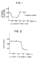
- Fig. 1 illustrates the correlation between amounts of Si added and friction coefficients of the magnetic layer undergone a curing process.
- addition of calcium further improves the surface properties of magnetic particles, greatly improving the dispersion of the magnetic powder into a paint, or, more specifically, into a binder.
- the preferred amount of aluminum added is 0.11 to 0.19 wt%; the preferred amount of calcium added is 0.06 to 0.14 wt%, and the preferred Si/Ca ratio is not less than 1.10.
- This type of magnetic powder exhibits peculiar wettability in conjunction with a binder that has a sulfo group and/or phospho group in the form of salt, in particular, in the form of alkali metal salt; or in conjunction with a bifunctional binder. This wettability seems to improve dispersibility of the magnetic powder to provide smooth magnetic surface.
- An amount of silicon or calcium added smaller than the above range results in insufficient surface improving effects; while a similar amount larger than the above range results in inferior electromagnetic conversion characteristics.
- An Si/Ca ratio smaller than 1.10 results in inferior dispersibility of the magnetic powder.
- the particularly preferred amount of silicon added is 0.12 to 0.16 wt%; the similar amount of calcium added is 0.08 to 0.12 wt%; and the preferred Si/Ca ratio is 1.10 ⁇ Si/Ca ⁇ 2.5, in particular, 1.20 ⁇ Si/Ca ⁇ 2.2.
- the amount of silicon and zinc combinedly added to the ferromagnetic iron oxide powder is usually within a range of 0.10 to 0.25 wt%, or, preferably, within a range of 0.12 to 0.25 wt%. If the amount is less than 0.10 wt%, the surface activity of the ferromagnetic iron oxide particles may not be satisfactorily limited, and it may be impossible to inhibit an excessive amount of a binder having a functional group, or dispersing agent, from being adsorbed on the ferromagnetic iron oxide particles. On the other hand, the amount exceeding 0.25 wt% sometimes fails to provide an effect expected based on the amount, and, worse, may deteriorate the magnetic characteristics of the magnetic particles.
- the Si/Zn ratio, Si:Zn is usually within a range of 30:1 to 1:30, or, preferably, within a range of 20:1 to 1:10.
- Magnetic materials useful in embodying the invention include oxide based magnetic materials such as ⁇ -Fe2O3, Co-containing ⁇ -Fe2O3, Co-coated ⁇ -Fe2O3, Fe3O4, Co-containing Fe3O4, Co-coated Fe3O4, and CrO2.
- oxide based magnetic materials such as ⁇ -Fe2O3, Co-containing ⁇ -Fe2O3, Co-coated ⁇ -Fe2O3, Fe3O4, Co-containing Fe3O4, Co-coated Fe3O4, and CrO2.
- the BET of any of such materials is within a range of 20 to 60 m2/g.
- a predetermined amount of such elements is added during the final step in the manufacturing process of the similar powder, or is added to a liquid dispersion containing the similar powder.
- aqueous ferrous sulfate solution nuclei ⁇ -FeOOH and metal iron, and the mixture is heated with air bubbling thereinto, and then, the iron component dissolves into the solution by oxidation, generating -FeOOH that precipitates on the nuclei ⁇ -FeOOH, thereby crystal growth starts.
- the growth is terminated when, for example, the crystals have grown to a length of 0.6 to 1.0 ⁇ , a width of 0.1 to 0.3 ⁇ , and then, the crystals are subjected to filtration, water-rinsing, and drying, to obtain goethite powder.
- the goethite powder is further dehydrated and reduced in H2 gas flow at approx.
- ⁇ -Fe2O3 serving as nuclei for growing crystals is powdered into aqueous solution of iron sulfate and cobalt sulfate, where the solution containing predetermined amounts of Al, Si, Ca, Zn and the like, and then, alkali is added to the solution, thereby oxidation is allowed to continue for 1 to 3 hours at 60 to 80°C, in order to grow cobalt iron oxide on the surface of individual ⁇ -Fe2O3 particles. Then the ⁇ -Fe2O3 particles are subjected to filtration, water-rinsing, and drying, so as to obtain Co-coated ⁇ -Fe2O3 particles.
- the examples of a useful silicon compound include silicic acids such as orthosilicic acid (H4SiO4), metasilicic acid (H2SiO3), metadisilicic acid (H2Si2O5), metatrisilicic acid (H4Si3O8), and metatetrasilicic acid (H6Si4O11); silicon monoxide, and silicon dioxide; metal silicate salts such as sodium orthosilicate (Na4SiO4), sodium metasilicate (Na2SiO3), potassium metasilicate (K2SiO3), calcium orthosilicate (Ca4SiO4), calcium metasilicate (Ca2SiO3), barium metasilicate (Ba2SiO3), and cobalt metasilicate (CO2SiO3).
- silicic acids such as orthosilicic acid (H4SiO4), metasilicic acid (H2SiO3), metadisilicic acid (H2Si2O5), metatrisilicic acid (H
- the examples of a zinc compound useful for this purpose include zinc dust, zinc chloride (ZnCl2), zinc bromide (ZnBr2), zinc iodide (ZnI2), zinc nitrate, and zinc chlorate.
- the binder useful in embodying the invention is a wear-resistant polyurethane. This material is capable of being strongly adhering to another material, and is mechanically resilient to repeatingly exerting stress or bending force, and has strong wear resistance and weather resistance.
- the preferred polyurethane used for this purpose is one having a weight average molecular weight of 10000 to 200000, and glass transition point of -30 to 10°C.
- a useful cellulose resin examples include cellulose ether, inorganic acid ester of cellulose, and cellulose-containing organic acid ester.
- the above-mentioned vinyl chloride resin can be a resin of which portion having been hydrolyzed.
- the preferred vinyl chloride copolymer is a copolymer containing vinyl chloride-vinyl acetate.
- a vinyl chloride resin having an anionic functional group it is preferable to use a vinyl chloride resin having an anionic functional group.
- an anionic functional group in the above-mentioned resin examples include -SO3M, -OSO2M, -COOM, and (wherein M represents a hydrogen atom, lithium atom or sodium atom; M1 and M2 independently represent a hydrogen atom, lithium atom, potassium atom, sodium atom, or alkyl group; M1 and M2 may be identical or different with each other).
- the above-mentioned resin can be obtained, for example, by modifying a vinyl chloride resin to introduce the above-mentioned anionic functional group thereinto.
- such a resin can be obtained, based on a dehydrochlorination reaction, by allowing the vinyl chloride resin to react with a compound having in its molecular structure an anionic functional group and a chlorine atom, as exemplified by (wherein M, M1 and M2 are synonymous with those defined above).
- the examples of the above-mentioned vinyl chloride resin include vinyl chloride-vinyl acetate-vinyl alcohol copolymers, vinyl chloride-vinyl propionate-vinyl alcohol copolymers, vinyl chloride-vinyl acetate-vinyl maleate-vinyl alcohol copolymers, and vinyl chloride-vinyl propionate-vinyl maleate-vinyl alcohol copolymers.
- the introduction is achieved by subjecting not only an OH group on a vinyl alcohol in any of the above copolymers and but also a chlorine atom in the above-mentioned metal sulfonate salt such as Cl-CH2CH2SO3M, and Cl-CH2CHSO2M, to dehydrochlorination reaction in the presence of a dehydrochlorinating agent such as amine salt (for example, pyridine, picoline, and triethyl amine; and epoxy compound such as ethylene oxide, and propylene oxide.
- a dehydrochlorinating agent such as amine salt (for example, pyridine, picoline, and triethyl amine; and epoxy compound such as ethylene oxide, and propylene oxide.
- the particularly preferred are vinyl chloride copolymers.
- Such vinyl chloride copolymers can be obtained by copolymerizing vinyl chloride monomers; copolymerizable monomers containing an alkaline salt of sulfonic acid or phosphoric acid; and, according to a requirement, another type of copolymerizable monomers.
- This type of copolymer can be readily synthesized since it is obtained by vinyl synthesizing, and, additionally, various copolymerizable components can be arbitrarily employed for this purpose, thereby the optimum copolymer characteristics can be arbitrarily designed.
- the metals in the form of a sulfonate salt or phosphorate salt are alkali metals such as sodium, potassium, and lithium.
- the especially preferred is potassium from the viewpoints of solubility, reactivity, and product yield.
- the examples of the above-mentioned copolymerizable monomer containing a sulfonate salt include:
- the examples of a copolymerizable monomer used in compliance with a requirement include various vinyl esters, vinyl chloridene, acrylonitrile, methachrylonitirile, styrene, acrylic acid, methacrylic acid, various acrylic acid esters, methacrylic acid esters, ethylene, propylene, isobutene, butadiene, isoprene, vinyl ether, aryl ether, aryl ester, acrylamide, methacryl amide, maleic acid, and maleic acid ester.
- the previously mentioned binders can be synthesized by any of various polymerization processes such as emulsification polymerization, solution polymerization, suspension polymerization, and block polymerization.
- polymerization processes known techniques such as use of a molecular weight adjuster, polymerization initiator, and step-by-step addition or continuous addition of monomers.
- the amount of a monomer containing the above-mentioned acid group salt, as contained in a binder is preferably 0.01 to 30 mol%.
- An excessively large amount of such a salt-containing monomer results in difficulty for the binder in being dissolved in a solvent, or is prone to cause gelation.
- an excessively small amount of such a monomer may result in failure in achieving intended characteristics.
- the above-mentioned vinyl chloride copolymer preferably contains an epoxy or hydroxy group.
- a prior art vinyl chloride is, for example, a copolymer of monomer units such as below. [wherein j, k and l independently represent an integer].
- the CH3CO-O- group in these examples seems to be a group not readily contributing to the crosslinking reaction with a curing agent or the like.
- an epoxy group such as; is preferably contained in these examples in place of the CH3CO.
- those resins in the form of combination of the following units are available: [wherein q, r and s are synonymous with those defined previously, and t represents an integer; Z represents a monomer unit containing alkali metal salt of sulfo group or phospho group].
- the molecular weight of each of the above-mentioned resins is usually 5000 to 80000, or, preferably, 10000 to 30000. If the molecular weight is greater than 80000, viscosity of a magnetic paint is greater than a permissible range, thereby the friction coefficient of the magnetic layer of the resultant magnetic recording medium can be disadvantageously large, or operation efficiency in a production process can be deteriorated. On the other hand, if the molecular weight is smaller than 5000, and when a magnetic paint is applied onto the previously mentioned non-magnetic support and is cured using a curing agent, a certain area fail to undergo polymerization reaction, thereby a resultant low molecular weight area deteriorates the properties of the resultant layer.
- the blending ratio of the above-mentioned resin is usually 5 to 30 parts by weight, or, preferably, 10 to 20 parts by weight per 100 parts of the ferromagnetic powder.
- the blending ratio is smaller than 5 parts by weight may result in poor dispersion of the ferromagnetic powder in the magnetic layer, and can possibly deteriorate the electromagnetic conversion characteristics, traveling characteristics, and durability of the magnetic recording medium of the invention.
- the blending ratio larger than 30 parts by weight may fail to provide effects proportional to the increase in the ratio.
- Phenoxy resins can be used as a binder too.
- Phenoxy resins have various advantages: larger mechanical strength; excellent dimension stability; good resistance to heat, moisture, and chemicals; and good adhesion.
- the most favorable binder is a binder in the form of a binder mixture of a polyurethane resin, and a vinyl chloride resin having the previously mentioned anionic functional group.
- the binder mixture may contain a thermoplastic resin, thermosetting resin, reactive resin, and electron beam-setting resin.
- an arbitrary curing agent can be incorporated into a magnetic paint, and one example of which is isocyanate.
- the useful aromatic isocyanates include tolylenediisocyanate (TDI), and the like; and adducts of these isocyanates and active hydride compounds. Those advantageous are the similar isocyanates having an average molecular weight of 100 to 3000.
- the useful fatty acid isocyanates include hexamethylenediisocyanate (HMDI), and the like; and adducts of these isocyanates and active hydride compounds.
- HMDI hexamethylenediisocyanate
- Those advantageous among these examples are the similar isocyanates or adducts having an average molecular weight of 100 to 3000.
- these fatty acid isocyanates those especially favorable are non-alicyclic isocyanates and adducts of these compounds and active hydride compounds.
- a magnetic paint used for forming the magnetic layer contains a dispersing agent, and, according to specific requirements, additives such as a lubricant, abrasive, matting agent, and antistatic agent.
- a dispersing agent used in the invention include lecithin, phosphoric esters, amine compounds, alkyl sulfates, fatty acid amides, higher alcohols, polyethylne oxides, sulfosuccinic acid, sulfosuccinic acid esters, and known surfactants, and salts thereof.
- a polymer dispersing agent having an anionic organic group for example, -COOH-PO3H
- the especially preferable are phosphoric esters whose structures represented by the following general formula.
- the examples of a resin group represented by R include an alkyl group, alkoxy group, and alkenyl group.
- the alkyl group having 1 to 20 carbon atoms is especially favorable.
- n represents a positive integer of 30 and greater, and whose maximum value being 300, and, preferably, within a range of 40 to 200.
- An amount of such a phosphoric ester added is preferably 0.1 to 10 parts by weight, in particular, 0.1 to 6 parts by weight per 100 parts magnetic powder.
- dispersing agents can be used singly or in combination. Such a dispersing agent is added at a rate of 1 to 20 parts by weight per 100 parts by weight binder.
- a useful lubricant examples include silicon oil, graphite, Carbon Black graft polymer, molybdenum disulfide, tungsten disulfide, lauric acid, myristic acid; monobasic fatty acid having 12 to 16 carbon atoms, and fatty acid ester (known as wax) having monovalent alcohol wherein a number of total carbon atoms in the fatty acid and alcohol is 21 to 23.
- Such a lubricant is added at a rate of 0.2 to 20 parts by weight per 100 parts by weight binder.
- the preferred abrasive is non-magnetic powder having Moh's hardness of not less than 5.0 and the examples of which include powders of chromium oxide, titanium oxide, ⁇ -iron oxide, silicon oxide, silicon nitride, silicon carbide, zirconium oxide, zinc oxide, cerium oxide, magnesium oxide, boron oxide, and alumina. Those preferred are alumina, chromium oxide, and ⁇ -iron oxide.
- the preferred average particle size is 0.05 to 2.0 ⁇ m, in particular, 0.1 to 1 ⁇ m.
- the preferred amount added is 1 to 15 wt%.
- the amount not more than 4 to 12 wt% results in decreased improvement on durability; in contrast, the amount exceeding 12 wt% results in deteriorated electromagnetic conversion characteristics.
- organic powder and inorganic powder are used independently or mixedly.
- organic powder used in embodying the invention include acryl styrene resin powder, benzoguanamine resin powder, melamine resin powder, and phthalocyanine pigment powder; and, additionally, other useful examples of which include polyolefin resin powder, polyester resin powder, polyamide resin powder, polyimide resin powder, and polyfluoroethylene resin powder.
- useful inorganic powder include silicon oxide, titanium oxide, aluminum oxide, calcium carbonate, barium sulfate, zinc oxide, tin oxide, aluminum oxide, chromium oxide, silicon oxide, calcium carbonate, ⁇ -Fe2O3, talc, caolite, calcium sulfate, boron nitride, zinc fluoride, and molybdenum dioxide.
- a useful antistatic agent include electrically conductive powders of Carbon Black, graphite, tin oxide-antimony oxide compounds, and titanium oxide-antimony oxide compounds; natural surfactants such as saponin; nonionic surfactants, such as alkylene oxides, glycerines, and glycidols; cationic surfactants, such as alkyl amines, quaternary ammonium salts, pyridine, and other heterocylic compounds, and phosphonium or sulfonium compounds; anionic surfactants, containing an acid group such as carboxylic acid, sulfonic acid, phosphoric acid, sulfuric ester, and phosphoric ester; amphoteric surfactants, such as amino acids, aminosulfonic acids, and sulfuric or phosphoric esters of aminoalcohols.
- the examples of useful Carbon Black are those of average particle size of 10 to 70 m ⁇ , and, more specifically, those of DBP absorption of not less than 100 ml/100 g.
- the particularly advantageous mode of embodying the invention is that the magnetic layer contain two types of Carbon Black of different average primary particle sizes.
- the first Carbon Black decreases the friction coefficient of the magnetic layer of the magnetic recording medium of the invention, thereby the traveling characteristics of the medium are improved.
- the average primary particle size of the first Carbon Black is within a range of 11 to 25 m ⁇ . If the average primary particle size is less than 11 m ⁇ , dispersibility of the ferromagnetic powder in the magnetic layer is possibly smaller. On the other hand, if the average primary particle size exceeds 25 m ⁇ , the surface roughness of the magnetic layer is possibly greater, and may cause deterioration in electromagnetic conversion characteristics of the layer.
- the second Carbon Black improves dispersion status of the ferromagnetic powder in the magnetic layer of the magnetic recording medium of the invention, thereby the friction coefficient of the layer is decreased.
- the average primary particle size of the second Carbon Black is within a range of 30 to 45 m ⁇ . If the average primary particle size is less than 30 m ⁇ , dispersibility of the ferromagnetic powder in the magnetic layer is possibly smaller, and, the friction coefficient of the layer is greater, thereby improvement on the traveling characteristics of the magnetic tape may be insufficient. On the other hand, if the average primary particle size exceeds 45 m ⁇ , the surface roughness of the magnetic layer is possibly greater, and may cause deterioration in electromagnetic conversion characteristics of the layer.
- the blending ratio, in the magnetic layer, of the first Carbon Black and the second Carbon Black is, in terms of weight ratio of (second Carbon Black) to (first Carbon Black), usually, 99:1 to 30:70, or, preferably, within a range of 99:1 to 60:40.
- a solvent incorporated into a magnetic paint of the invention or of a solvent that is added to a solvent for dilution, include ketones such as acetone, methyl ethyl ketone, methyl isobutyl ketone, and cyclohexanone; alcohols such as methanol, ethanol, propanol, and butanol; esters such as methyl acetate, ethyl acetate, butyl acetate, ethyl lactate, and ethylene glycol monoacetate; ethers such as glycol dimethyl ether, glycol monoethyl ether, dioxane, and tetrahydrofurane; aromatic hydrocarbons such as benzene, toluene, and xylene; halogenated hydrocarbons such as methylene chloride, ethylene chloride, carbon tetrachloride, chloroform, and dichlorobenzene.
- ketones such as acetone, methyl eth
- the preferred elastic modulus of the magnetic layer is not less than 450 kg/mm2; the preferred density being within a range of 1.7 to 2.0 g/cm3; and the preferred surface roughness being not more than 0.015 ⁇ m.
- the elastic modulus of the magnetic layer can be enhanced to not less than 450 kg/mm2 by mixedly using polyurethane, and a vinyl chloride or the like whose Tg being greater than that of the polyurethane used.
- the density can be adjusted to an intended range by selected material types used and mixing ratio; Ra can be similarly adjusted by selecting calendering conditions.
- a useful support examples include polyesters such as polyethylne terephthalate, and polyethylene-2,6-naphthlate; polyolefins such as polypropylene; cellulose derivatives such as cellulose triacetate, and cellulose diacetate; plastics such as polyamide, and polycarbonate.
- Other useful supports include metals such as Cu, Al, and Zn; and ceramics such as glass, BN, and Si carbide.
- the thickness of the support is, in the form of film or sheet, approx. 3 to 100 ⁇ m, or, preferably, 5 to 50 ⁇ m; in the form of disk or card, 30 ⁇ m to 10 mm. If the support is in the drum form, that is, in a cylindrical form, the configuration of which is dependent upon a recorder used.
- Between the support and he magnetic layer can be disposed an intermediate layer that improves adhesion between the layers.
- the examples of a useful coating technique for forming the magnetic layer upon the support include the air-doctor coating process, blade-coating process, air-knife coating process, squeeze-coating process, impregnation-coating process, reverse-coating process, transfer-roller coating process, gravure-coating process, kiss-roll coating process, cast coating process, and spray coating process.
- these processes are not mandatory.
- the magnetic recording medium of the invention can be used as a video tape, audio tape, floppy disk or the like.
- the magnetic layer on the floppy disk preferably contains, because of the affinity on the part of the liners that are in contact with the floppy disk, oleic acid ester multivalent alcohol), wherein the liner is an nonwoven cloth containing each of polyether and rayon resins in an amount, respectively, of not less than 40 wt%.
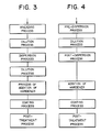
- the medium is preferably prepared according to any of the following procedures:
- the preferred viscosity of a solution undergoing treatment in each step ranging from the dispersing step up to an actual coating operation is not in excess of 10000 cps.
- orientation/drying process is performed.
- An orientation station is disposed in plurality, wherein drying preferably is performed so that the magnetic powder/solvent ratio by weight, in the magnetic layer formed with the magnetic coating solution, at the final orientation station, is 1/1.3 to 1/1.7, and so that the drying is complete at the very last portion of the final orientation station.
- the magnetic layer, or both side edges of the layer and the back face of the magnetic medium are preferably subjected to a wiping process after the drying, and prior to the calendering process.
- the wiping operation is preferably performed using a nonwoven cloth having an embossed face.
- a preferred nonwoven fabric material is a blended fabric type nonwoven cloth comprising 30 to 85% rayon, and 70 to 15% polypropylene and/or polyester.
- a further preferable mode of the invention is to collect dust particles via a nonwoven cloth.
- the above specified magnetic paints were independently applied to and dried on a polyethylne terephthalate film, and then, the respective films were slit to prepare individual magnetic tape samples.
- the resultant measurements on characteristics of the respective magnetic tapes are listed in Table 2.
- Level 3 means that a rate is within an industrially acceptable range; level 5, a rate is significantly high; and level 1, a rate is significantly low.
- o means viscosity remains constant during standing; ⁇ , viscosity remains within an industrially acceptable range in spite of increase; x, increased viscosity jeopardized industrial usefulness of paint.
- Traveling characteristics of a magnetic tape are evaluated on two level evaluation system. o means there are virtually no trouble in traveling of the tape; x, occasional troubles.
- each of example sample satisfactorily satisfies each criterion on paint properties and on the traveling characteristics of the magnetic tape.
- comparative examples in general exhibit poor similar properties as well as poor similar characteristics, and, even if satisfying two or three criteria, these comparative examples fail to satisfy industrially acceptable levels in remaining criteria.
- compositions specified below were poured into a sand mill and dispersed, and then, additives were added for diluting.
- the resultant magnetic paint was filtered with a 1 ⁇ m mesh filter, and, polyvalent isocyanate (Coronate L, Nippon Polyurethane Kogyo) was added, and the paint was applied onto a support so that the dry thickness of the magnetic layer for formed was 5 ⁇ m, thereby the support was subjected to a supercalendering process, and was slit into 1/2 inch strips, thus the videotape samples according to the invention were obtained.
- Co-coated ⁇ -Fe2O3 (same as in Example 1) 100 wt parts Alumina (ave.
- Example samples 7 were prepared based on a recipe identical with that of Example 6 except that 1 wt part phosphoric acid ester was added.
- Comparative samples were prepared based on a recipe identical with that of Example 6 except that the vinyl chloride-vinyl acetate copolymer of the invention was replaced with an equivalent amount of vinyl chloride-vinyl acetate copolymer, VAGH, manufactured by Union Carbide, (lacking either a sulfo group or epoxy group).
- VAGH vinyl chloride-vinyl acetate copolymer
- Samples were prepared based on a recipe identical with that of Example 6 except that the vinyl chloride-vinyl acetate copolymer of the invention was replaced with an equivalent amount of vinyl chloride copolymer (polymer resin formed by eliminating a vinyl acetate component in the resin of Example 1).
- Samples were prepared based on a recipe identical with that of Example 6 except that alumina, Carbon Blacks A, and B were eliminated.
- the RH output was measured (unit, in dB).
- This item was measured using a color video noise meter, Model 925 D/1, manufactured by Shibasoku.
- a magnetic tape was allowed to run for 200 passes as loaded on a video tape deck, and then, the contamination on the reading/recording head (powder departed) was collected, thereby this item was visually evaluated.
- samples according to the invention have good electromagnetic conversion characteristics, and physical properties, and particularly excel in durability.
- Table 4 Numerical data in Table 4 represents parts by weight, and "Exam” means an example according to the invention.
- Table 4 Invention 1 Invention 2 Co-coated -Fe2O3 (same as in Example 1) 100 100 Alumina 7 7 Carbon Black 10 10 Vinyl chloride resin containing SO3Na salt 20 20 Resin containing vinyl chloride with OH and vinyl acetate*1 0 0 Polyurethane resin*2 10 20 Phosphoric ester*3 n ⁇ 30 0 0 n ⁇ 30 3 3 Lecithin 0 0 Stearing acid 2 2 Butyl stearate 1 1 Polyvalent isocyanate 10 10 Methyl ethyl ketone 150 150 Toluene 150 150 *1 VAGH, Union Carbide *2 N-2304, Nippon Polyurethane *3 GAFAC (Toho Kagaku) RE610 (n ⁇ 30) RE960 (n ⁇ 30)
- Video tape samples prepared in the above examples were evaluated based on the following criteria, for dispersibility of magnetic paint used, and for electromagnetic conversion characteristics of the video tapes, and hydrolitic dissociation resistance of the magnetic layer.
- This item was measured with a color video noisemeter, Shibasoku Model 925 D/1.
- the chroma output at 500 KHz was measured in a manner identical with that of the RF output (unit, in dB).
- samples of the invention exhibited good dispersion status of magnetic powder, and, accordingly, the samples of the invention excel in electromagnetic conversion characteristics, as well as physical properties (durability under high temperature, high humidity environments, in particular).
- a vinyl chloride copolymer containing a salt was synthesized in the following manner.
- compositions specified below were poured into a reaction vessel, and air within the vessel was replaced with N2, thereby chemical reaction was allowed to occur.
- Methyl isobutyl ketone 86 wt parts
- Methyl acetate 280 wt parts
- Vinyl chloride 150 wt parts
- CH2 CHCH2OCOCH(SO3K)CH2COOC8H17 6 wt parts
- the mixture comprising the above compositions was heated to 53°C with stirring, and methyl isobutyl ketone was added in an amount of 9 parts per 1 part polymerization initiator specified in the recipe above. 15 hours after, the mixture was allowed to cool to 30°C, and residual vinyl chloride was removed for reuse, and the removal procedure was perfected under a reduced pressure. Thus 480 parts by weight of copolymer solution whose solid portion being 32%, and viscosity 70 cps (25°C) was obtained, and this product was designated binder A. Then the magnetic paint of the following composition was prepared.
- the above components were poured into a ball mill, and dispersed, and then, 5 parts trifunctional isocyanate was added to the resultant paint, which as applied onto a support in a thickness of 5 ⁇ m, thereby the support was subjected to a supercalendering process.
- the resultant magnetic tape was slit into 1/2" strips to prepare individual video tapes.
- the RH output at 5 MHz was measured.
- the measurement values are indicated based on that of a reference video tape, that is a video tape of Comparative Example 1 having undergone 100 times of data reproducing (unit, in dB).
- This item was measured using a color video noise meter, Model 925 D/1, manufactured by Shibasoku. The measurement values are indicated using a difference from the lumi S/N ratio of the video tape of Comparative Example 1, i.e. a reference video tape (0 dB).
- the threshold level of the high pass filter was 4.2 MHz, and that of the low pass filter was 10 KHz.
- This item was measure using a number of image dropouts on a reproduced image.
- a degree of loss in still image output for a duration of 2 hours was indicated in dB.
- Table 7 lists the characteristics of each recording medium. Table 7 RF output (dB) Lumi S/N (dB) Dropout (-12 dB, 15 ⁇ s) Still image durability (dB/2 hr) Squareness ratio Post-traveling powder departure Example 10 +2.2 +2.0 2 -0.5 0.85 OK o Example 11 +2.0 +1.9 4 -0.4 0.83 OK o Example 12 +2.1 +1.9 1 -0.4 0.85 OK o Example 13 +2.2 +1.8 5 -0.2 0.86 OK o Example 14 +2.1 +2.0 4 -0.4 0.84 OK o
- the so-obtained magnetic paint was applied to and dried on a 15 ⁇ m thick polyethylene terephthalate film so that the dry thickness of the magnetic layer formed was 4 ⁇ m.
- each film was subjected to a surface smoothing process under the conditions of a temperature of 60 to 80°C, and pressure of 100 to 300 kg/cm, by using a supercalender, and then, each film was slit into strips of a specified width.
- video tape samples were prepared.
- Each video tape sample was evaluated for characteristics and physical properties.
- the surface coarseness of a magnetic tape was measured using a coarseness analyzer, Model SE-3FK manufactured by Kosaka Kenkyusho (cutoff level, 0.25 mm).
- This item was measured, under conditions of tape speed of 3.3 cm/sec. and tape tension of 20 g, by using a MSC tape travel tester manufactured by Yokohama System, both before and after a curing process (temperature, 70°C; 12 hours).
- This item was evaluated using, as a reference output, the output of the video tape of Example 2, obtainable when reproducing 100% white signal.
- This item was measured using a video noise meter, manufactured by Shibasoku, where the S/N, based on 100% white signal, of each video tape sample was compared with that of a reference tape manufactured by Konica.
- This item was measured using a video noise meter, manufactured by Shibasoku, where the S/N, based on chroma signal, of each video tape sample was compared with that of a reference tape manufactured by Konica.
- Video tape samples were prepared in a manner identical with that of the previously described Example 15 except that for preparing a magnetic paint, the ferromagnetic iron oxide powder in Example 15 was replaced with each of the ferromagnetic iron oxide powders listed in Table 8, and then, the characteristics of the so-obtained video tape samples were examined.
- Table 8 Amount in ferromagnetic iron oxide powder Surface coarseness of magnetic layer ( ⁇ m) Friction coefficients, before and after curing process (before/after) Magnetic characteristics Traveling characteristics test (temperature, 40°C; humidity, 80%) Electromagnetic conversion characteristics Si (wt%) Zn (wt%) Squareness ratio (Br/Bm) RF output (db) Lumi S/N (db) Chroma S/N (db) Example 15 0.13 0.01 0.011 0.18/0.18 0.83 Completed 100 hour operation +0.2 +0.1 +0.2 Comparative Example 9 0.02 0.01 0.018 0.19/0.31 0.81 Stopped, at 40 hours -0.2 -0.1 -0.3 Comparative Example 10 0.02 0.60 0.021 0.19/0.33 0.76 Stopped, at 48 hours -1.0 -1.2 -1.1 Comparative Example 11 0.35 0.01 0.018 0.20/0.21 0.71 Stopped, at 80 hours -1.5 -1.3 -1.2 Comparative Example 12 0.35 0.06 0.0
- the magnetic layer of the magnetic medium according to the invention is free from deterioration in magnetic characteristics, and loss in friction coefficient even after a curing process.
- the reason for such an advantage is that according to the invention, ferromagnetic iron oxide powder incorporates a specific amount of silicon and/or zinc to cover individual particles, thereby activity on the surface of individual ferromagnetic iron oxide particles can be controlled as intended, and thereby appropriate amounts of dispersing agent, function group-containing binder, and lubricant are adsorbed on the individual particles, thus the dispersion status of ferromagnetic iron oxide powder in the magnetic layer is positively improves, and, at the same time, the elution of lubricant during a curing process is prevented. It is also apparent that the surface smoothness of the magnetic layer on the magnetic recording medium of the invention is small, and that there are positive improvements in traveling characteristics, magnetic characteristics, and electromagnetic conversion characteristics of the medium.
- a high performance magnetic recording medium whose advantages include the following:
- Video tape samples were prepared based on the processes in Fig. 3.
- Co-coated iron oxide (containing Si and Al in amounts equivalent to those of Example 1) (BET value in Example 16, 40 m2/g; in Example 17, 45 m2/g; in Comparative Example 14, 25 m2/g) 100 parts Vinyl chloride copolymer resin containing sulfo group 10 parts Carbon Black 3 parts RP-710 (phosphoric acid ester) 3 parts Al2O3 4 parts Methyl ethyl ketone 50 parts
- the kneaded product was subjected to dispersing for 2 hours using a sand grinder.
- liquid dispersion was diluted with the following components.
- MA myristic acid
- SA stearic acid
- Bust butyl stearate
- Methyl ethyl ketone 40 parts
- Each magnetic coating solution was applied to and dried on a 14 ⁇ m thick polyester base film using a reverse roller coater so that the dry thickness of the magnetic layer formed was 5.0 ⁇ m.
- Each film was subjected to a surface smoothing process, and then, to a curing process, and was slit into 1/2" strips.
- Video tapes were prepared based on the processes in Fig. 4.
- Co-coated iron oxide (BET value in Comparative Example 15, 25 m2/g; in Comparative Example 16, 40 m2/g) 100 parts Vinyl chloride copolymer resin containing sulfo group 10 parts Carbon Black 3 parts RP-710 (phosphoric acid ester) 3 parts Al2O3 4 parts Methyl ethyl ketone 80 parts Toluene 40 parts
- Each magnetic coating solution was applied to and dried on a 14 ⁇ m thick polyester base film using a reverse roller coater so that the dry thickness of the magnetic layer formed was 5.0 ⁇ m.
- Each film was subjected to a surface smoothing process, and then, to a curing process, and was slit into 1/2" strips.
- Br/Bm was determined at Hm 5KOe, using a sample-vibrating type fluxmeter (manufactured by Toei Kogyo).
- Noise levels were determined using a high pass filter whose threshold level being 10 KHz, and a low pass filter whose threshold level being 4 MHz.
- the video tape deck used was Model NV 8300 manufactured by Matsushita.
- Each video tape sample was allowed to run for 200 hours at 40°C, and 80%RH, thereby RF output loss, skew, and powder departure were measured.
- A indicates good; B, ordinary; and C, unsatisfactory.
- Each video tape sample was loaded into a tape travel tester, Model TBT-300D manufactured by Yokohama System Kenkyusho as wound 180° around a 4 mm dia. cromium-plated stainless pin, and at 25°C, the friction coefficitent was measured at a tape speed 1 cm/sec. and entrance tension of 20 g, and then, ⁇ k ws arithmetically determined with the expression below.
- magnetic recording media provides video tapes of good dispersibility, high squareness ratio and S/N ratio, good surface characteristics, and small friction coefficient, and of excellent traveling characteristics.
- Video tape samples were prepared, based on the processes in Fig. 3.
- Co-coated iron oxide (containing Si and Al in amounts equivalent to those of Example 1) (BET value in Example 18 and Comparative Example 18, 40 m2/g; in Example 19, 25 m2/g) 100 parts Vinyl chloride copolymer resin containing sulfo group 10 parts Urethane resin (average molecular weight, 60000 in Examples 18 and 19, and in Comparative Example 17; 100000 in Comparative Example 18) 6 parts Carbon Black 3 parts RP-710 (phosphoric acid ester) 3 parts Al2O3 4 parts Methyl ethyl ketone 40 parts
- the kneaded product was subjected to dispersing for 2 hours using a sand grinder.
- liquid dispersion was diluted with the following components.
- MA myristic acid
- SA stearic acid
- Bust butyl stearate
- Methyl ethyl ketone 40 parts
- Each magnetic coating solution was applied to and dried on a 14 ⁇ m thick polyester base film using a reverse roller coater so that the dry thickness of the magnetic layer formed was 5.0 ⁇ m.
- Each film was subjected to a surface smoothing process, and then, to a curing process, and was slit into 1/2" strips.
- Video tapes were prepared based on the processes in Fig. 4.
- Co-coated iron oxide (BET value in Comparative Example 19, 25 m2/g; in Comparative Example 20, 40 m2/g;) 100 parts Vinyl chloride copolymer resin containing sulfo group 10 parts Carbon Black 3 parts RP-710 (phosphoric acid ester) 3 parts Al2O3 4 parts Methyl ethyl ketone 80 parts Toluene 40 parts
- Each magnetic coating solution was applied to and dried on a 14 ⁇ m thick polyester base film using a reverse roller coater so that the dry thickness of the magnetic layer formed was 5.0 ⁇ m.
- Each film was subjected to a surface smoothing process, and then, to a curing process, and was slit into 1/2" strips.
- Br/Bm was determined at Hm 5KOe, using a sample-vibrating type fluxmeter (manufactured by Toei Kogyo).
- Noise levels were determined using a high pass filter whose threshold level being 10 KHz, and a low pass filter whose threshold level being 4 Hz.
- the video tape deck used was Model NV 8300 manufactured by Matsushita.
- Each video tape sample was allowed to run for 200 hours at 40°C, and 80%RH, thereby RF output loss, skew, and powder departure were measured.
- A indicates good; B, ordinary; and C, unsatisfactory.
- Each video tape sample was loaded into a tape travel tester, Model TBT-300D manufactured by Yokohama System Kenkyusho as wound 180° around a 4 mm dia. cromium-plated stainless pin, and at 25°C, the friction coefficitent was measured at a tape speed 1 cm/sec. and entrance tension of 20 g, and then, ⁇ k ws arithmetically determined with the expression below.
- magnetic recording media provides video tapes of good dispersibility, high squareness ratio and S/N ratio, good surface characteristics, and small friction coefficient, and of excellent traveling characteristics.
- each of videotapes of Examples 20 and 21, and Comparative Examples 21 through 23 was prepared as follows.
- Video tape samples were prepared ,based on the processes in Fig. 5.
- Co-coated iron oxide (containing Si and Al in amounts equivalent to those of Example 1) (BET value in Example 20, 40 m2/g; in Example 21, 45 m2/g; in Comparative Example 21, 25 m2/g) 100 parts Vinyl chloride copolymer resin containing sulfo group 10 parts RP-710 (phosphoric acid ester) 2.7 parts Methyl ethyl ketone 50 parts
- the kneaded product was subjected to dispersing for 2 hours using a sand grinder.
- liquid dispersion was diluted with the following components.
- MA myristic acid
- SA stearic acid
- Bust butyl stearate
- Methyl ethyl ketone 40 parts
- Each magnetic coating solution was applied to and dried on a 14 ⁇ m thick polyester base film using a reverse roller coater so that the dry thickness of the magnetic layer formed was 5.0 ⁇ m.
- Each film was subjected to a surface smoothing process, and then, to a curing process, and was slit into 1/2" strips.
- Video tapes were prepared based on the processes in Fig. 4.
- Co-coated iron oxide (BET value in Comparative Example 22, 25 m2/g; in Comparative Example 23, 40 m2/g) 100 parts Vinyl chloride copolymer resin containing sulfo group 10 parts Carbon Black 3 parts RP-710 (phosphoric acid ester) 3 parts Al2O3 4 parts Methyl ethyl ketone 80 parts Toluene 40 parts
- Each magnetic coating solution was applied to and dried on a 14 ⁇ m thick polyester base film using a reverse roller coater so that the dry thickness of the magnetic layer formed was 5.0 ⁇ m.
- Each film was subjected to a surface smoothing process, and then, to a curing process, and was slit into 1/2" strips.
- Br/Bm was determined at Hm 5KOe, using a sample-vibrating type fluxmeter (manufactured by Toei Kogyo).
- Noise levels were determined using a high pass filter whose threshold level being 10 KHz, and a low pass filter whose threshold level being 4MHz.
- the video tape deck used was Model NV 8300 manufactured by Matsushita.
- Each video tape sample was allowed to run for 200 hours at 40°C, and 80%RH, thereby RF output loss, skew, and powder departure were measured.
- A indicates good; B, ordinary; and C, unsatisfactory.
- Each video tape sample was loaded into a tape travel tester, Model TBT-300D manufactured by Yokohama System Kenkyusho as wound 180° around a 4 mm dia. cromium-plated stainless pin, and at 25°C, the friction coefficitent was measured at a tape speed 1 cm/sec. and entrance tension of 20 g, and then, ⁇ k ws arithmetically determined with the expression below.
- magnetic recording media provides video tapes of good dispersibility, high squareness ratio and S/N ratio, good surface characteristics, and small friction coefficient, and of excellent traveling characteristics.
- the kneaded product was subjected to dispersing for 2 hours using a sand grinder.
- Each magnetic coating solution was applied to and dried on a 14 ⁇ m thick polyester base film using a reverse roller coater so that the dry thickness of the magnetic layer formed was 5.0 ⁇ m.
- Each film was subjected to a surface smoothing process, and then, to a curing process, and was slit into 1/2" strips.
- Video tapes were prepared based on the processes in Fig. 4.
- the following components were subjected to dispersing for 4 hours using a sand grinder.
- Each magnetic coating solution was applied to and dried on a 14 ⁇ m thick polyester base film using a reverse roller coater so that the dry thickness of the magnetic layer formed was 5.0 ⁇ m.
- Each film was subjected to a surface smoothing process, and then, to a curing process, and was slit into 1/2" strips.
- Br/Bm was determined at Hm 5KOe, using a sample-vibrating type fluxmeter (manufactured by Toei Kogyo).
- Noise levels were determined using a high pass filter whose threshold level being 10 KHz, and a low pass filter whose threshold level being 4MHz.
- the video tape deck used was Model NV 8300 manufactured by Matsushita.
- Each video tape sample was allowed to run for 200 hours at 40°C, and 80%RH, thereby RF output loss, skew, and powder departure were measured.
- A indicates good; B, ordinary; and C, unsatisfactory.
- Each video tape sample was loaded into a tape travel tester, Model TBT-300D manufactured by Yokohama System Kenkyusho as wound 180° around a 4 mm dia. cromium-plated stainless pin, and at 25°C, the friction coefficitent was measured at a tape speed 1 cm/sec. and entrance tension of 20 g, and then, ⁇ k ws arithmetically determined with the expression below.
- Table 12 Relative surface area of iron oxide (m2g, BET) Layer forming process Squareness ratio Video S/N (dB) Traveling characteristics Dynamic friction coefficient ( ⁇ k)
- Example 22 40 Fig. 1 0.86 +3.2 A 0.18
- Example 23 45 Fig. 1 0.87 +3.8 A 0.17 Comparative Example 24
- Fig. 1 0.82 +0.0 B 0.24 Comparative Example 25 25 Fig. 2 0.82 +0.0 B 0.24 Comparative Example 26
- magnetic recording media provides video tapes of good dispersibility, high squareness ratio and S/N ratio, good surface characteristics, and small friction coefficient, and of excellent traveling characteristics.
- Video tape samples were prepared ,based on the processes in Fig. 3.
- Co-coated iron oxide (containing Si and Al in amounts equivalent to those of Example 1) (BET value in Example 24, 40 m2/g; in Example 25, 45 m2/g; in Comparative Example 27, 25 m2/g) 100 parts Vinyl chloride copolymer resin containing sulfo group 10 parts Urethane resin containing carboxyl group 6 parts Carbon Black 3 parts RP-710 (phosphoric acid ester) 3 parts Al2O3 4 parts Methyl ethyl ketone 40 parts
- the kneaded product was subjected to dispersing for 2 hours using a sand grinder.
- liquid dispersion was diluted with the following components.
- MA myristic acid
- SA stearic acid
- Bust butyl stearate
- Methyl ethyl ketone 40 parts
- Each magnetic coating solution was applied to and dried on a 14 ⁇ m thick polyester base film using a reverse roller coater so that the dry thickness of the magnetic layer formed was 5.0 ⁇ m.
- Each film was subjected to a surface smoothing process, and then, to a curing process, and was slit into 1/2" strips.
- Video tapes were prepared based on the processes in Fig. 4.
- Co-coated iron oxide (BET value in Comparative Example 28, 25 m2/g; in Comparative Example 29, 40 m2/g) 100 parts Vinyl chloride copolymer resin containing sulfo group 10 parts Carbon Black 3 parts RP-710 (phosphoric acid ester) 3 parts Al2O3 4 parts Methyl ethyl ketone 80 parts Toluene 40 parts
- Each magnetic coating solution was applied to and dried on a 14 ⁇ m thick polyester base film using a reverse roller coater so that the dry thickness of the magnetic layer formed was 5.0 ⁇ m.
- Each film was subjected to a surface smoothing process, and then, to a curing process, and was slit into 1/2" strips.
- Br/Bm was determined at Hm 5KOe, using a sample-vibrating type fluxmeter (manufactured by Toei Kogyo).
- Noise levels were determined using a high pass filter whose threshold level being 10 KHz, and a low pass filter whose threshold level being 4MHz.
- the video tape deck used was Model NV 8300 manufactured by Matsushita.
- Each video tape sample was allowed to run for 200 hours at 40°C, and 80%RH, thereby RF output loss, skew, and powder departure were measured.
- A indicates good; B, ordinary; and C, unsatisfactory.
- Each video tape sample was loaded into a tape travel tester, Model TBT-300D manufactured by Yokohama System Kenkyusho as wound 180° around a 4 mm dia. cromium-plated stainless pin, and at 25°C, the friction coefficitent was measured at a tape speed 1 cm/sec. and entrance tension of 20 g, and then, ⁇ k ws arithmetically determined with the expression below.
- magnetic recording media provides video tapes of good dispersibility, high squareness ratio and S/N ratio, good surface characteristics, and small friction coefficient, and of excellent traveling characteristics.
Abstract
Description
- The present invention relates to a magnetic recording medium, more specifically, to a magnetic layer of a magnetic recording medium of a coated type, and to a preparation process thereof.
- The magnetic recording media used on an information processing apparatus are indispensable as a recording-reproducing element and are widely used. What is required of this type of recording media include higher levels of electromagnetic conversion characteristics that are correctly reproduced; large recording capacity of higher density; appropriate composition properties that ensures good traveling operation, durability, and longer life; lower price; and trouble-free manufacturing process. To satisfy these requirements, various technical efforts have been exerted.
- To sum up, the objective of these technical efforts is essentially development of high performance magnetic media comprising fine particles of good electromagnetic performance, wherein individual particles are totally independent of others to ensure good dispersibility and good dispersion stability, and the media in the form of final product is free from troubles and has good durability.
- Using fine ferromagnetic powder of a good S/N ratio and large specific surface area, however, results in problems such as magnetic particles insufficiently dispersed in a binder, and a viscous magnetic paint. These problems in turn jeopardize the surface smoothness, durability, and magnetic characteristics of the magnetic layer, imposing difficulties in providing high performance magnetic recording media.
- Additionally, in regards with dispersibility of the magnetic powder, studies have been focused both on a dispersion agent and binder.
- Such magnetic recording media also incurs various problems in production techniques.
- First, finer magnetic particles, and finer fillers such as Carbon Black powder result in decreased dispersibility, incurring many steps and longer time for a dispersion process, imposing an unsolved bottleneck in production technique.
- Second, the viscosity stability of the magnetic pain during standing is poor, making it difficult to positively form a uniformly thick coat as a magnetic layer. This in turn makes it mandatory to add, as a thinner, a large amount of a solvent, or a fatty acid, phosphoric ester or the like, causing cost increase, troubles by a residual solvent, loss in the Young's modulus, and, as a result, the recording medium is subject to jeopardized traveling characteristics, damages on edges, loss in RF output level, and jitter fluctuation.
- The magnetic recording medium having been provided with structural layers such as a magnetic layer is subjected to a curing process at 50 to 70°C for 24 to 48 hours in order to stabilize performance and properties, and to ensure conformity to quality standards. However, excessive smoothness on the medium surface results in syneresis of a solvent and additives, jeopardizing the traveling characteristics of the medium.
- To solve the above productivity problems, not only improvements in additives and manufacturing apparatuses but also magnetic powder and binder that are indispensable and major parts of the magnetic layer entail in-depth researches.
- The binders hitherto subjected to studies include various thermosetting resins such as polyurethane, cellulose, vinyl chloride resins and phenoxy resins; various resins modified by introduction of a polar group; various resins whose properties modified by an introduced polar group; and thermoplastic resins of unique behavior. These are combined in good compatibility so that the properties of the structural layers on the magnetic recording medium have been significantly improved, and, at the same time, the dispersibility and deposition of the magnetic powder, filler and the like have been positively improved. These improvements, however, are still insufficient.
- The studies on magnetic powder have been hitherto centered principally on electromagnetic conversion characteristics, and have lacked in the viewpoints mentioned above, though a few studies centered on pretreatment of magnetic powder using a dispersing agent, and examples where less than 0.1 wt% Si is added to magnetic powder incidentally suggest the solution to the problems. In other words, it is no exaggeration to say that conventional studies totally ignore possibility of treating the surface or inside of individual magnetic particles.
- The object of the present invention is to solve the problems of the prior art, and therefore, the invention provides a magnetic recording media characterized in that:
- (1) a post-curing magnetic tape does not show increase in friction coefficient, and has good traveling characteristics;
- (2) a liquid dispersion for the medium has good viscosity stability;
- (3) the medium in the form of a magnetic tape has a higher Young's modulus, and relatively free from residual solvent, and has good traveling characteristics;
- (4) the medium has excellent electromagnetic conversion characteristics;
- (5) the medium exhibits improved durability even under high temperature, high humidity environments;
- (6) the medium has good durability;
- (7) the magnetic layer of the medium exhibits good lubrication;
- (8) the magnetic medium provides a still image of good durability; and
- (9) magnetic powder for the medium exhibits good dispersibility.
- The object of the invention above is attained by a magnetic recording medium comprising a non-magnetic support provided thereon a magnetic layer containing a ferromagnetic iron oxide and a binder, wherein the ferromagnetic iron oxide contains Si and/or Aℓ at a rate of 0.10 to 0.25wt%.
-
- Fig. 1 is an explanatory diagram indicating, by using a graph, the effect of Si added to iron oxide powder.
- Fig. 2 is a graph illustrating the interrelation of amounts of silicon added to ferromagnetic iron oxide powder of a conventional magnetic recording medium versus squareness ratios.
- Fig. 3 is a flow chart illustrating a manufacturing process according to the invention.
- Fig. 4 is a flow chart illustrating a manufacturing process of a comparative embodiment.
- Figs. 5 and 6 are flow charts independently illustrating a manufacturing process according to the invention.
- According to the invention, Si and/or Aℓ being added to iron oxide is added in the course of generation of magnetic iron oxide powder, and is deemed present on the surface and inside of individual iron oxide particles.
- Fig. 1 illustrates the correlation between amounts of Si added and friction coefficients of the magnetic layer undergone a curing process.
- Once exceeding 0.1 wt% of total magnetic powder, the so-added silicon fully demonstrates its effect, while once exceeding 0.25 wt%, the silicon added unexpectedly loses its effect.
- It seems that an excessive amount of silicon added prevents a lubricant such as a fatty acid from being adsorbed on the magnetic particles, thereby the lubricant is eluted to the magnetic layer surface, causing blooming and the friction coefficient drastically increases.
- When incorporating Si into the magnetic powder, addition of calcium further improves the surface properties of magnetic particles, greatly improving the dispersion of the magnetic powder into a paint, or, more specifically, into a binder. According to this arrangement, the preferred amount of aluminum added is 0.11 to 0.19 wt%; the preferred amount of calcium added is 0.06 to 0.14 wt%, and the preferred Si/Ca ratio is not less than 1.10.
- This type of magnetic powder exhibits peculiar wettability in conjunction with a binder that has a sulfo group and/or phospho group in the form of salt, in particular, in the form of alkali metal salt; or in conjunction with a bifunctional binder. This wettability seems to improve dispersibility of the magnetic powder to provide smooth magnetic surface.
- An amount of silicon or calcium added smaller than the above range results in insufficient surface improving effects; while a similar amount larger than the above range results in inferior electromagnetic conversion characteristics. An Si/Ca ratio smaller than 1.10 results in inferior dispersibility of the magnetic powder. The particularly preferred amount of silicon added is 0.12 to 0.16 wt%; the similar amount of calcium added is 0.08 to 0.12 wt%; and the preferred Si/Ca ratio is 1.10 ≦ Si/Ca ≦ 2.5, in particular, 1.20 ≦ Si/Ca ≦ 2.2.
- When incorporating Si into the magnetic powder, addition of zinc at a rate of 0.001 to 0.50 wt% further enhances the effect of the invention.
- According to the invention, when using silicon in conjunction with zinc as mentioned above, the amount of silicon and zinc combinedly added to the ferromagnetic iron oxide powder is usually within a range of 0.10 to 0.25 wt%, or, preferably, within a range of 0.12 to 0.25 wt%. If the amount is less than 0.10 wt%, the surface activity of the ferromagnetic iron oxide particles may not be satisfactorily limited, and it may be impossible to inhibit an excessive amount of a binder having a functional group, or dispersing agent, from being adsorbed on the ferromagnetic iron oxide particles. On the other hand, the amount exceeding 0.25 wt% sometimes fails to provide an effect expected based on the amount, and, worse, may deteriorate the magnetic characteristics of the magnetic particles.
- When using silicon (Si) and zinc (Zn) as mentioned above, the Si/Zn ratio, Si:Zn, is usually within a range of 30:1 to 1:30, or, preferably, within a range of 20:1 to 1:10.
- According to the invention, apparatuses and material technologies hitherto used for manufacturing conventional magnetic tapes are applicable.
- Magnetic materials useful in embodying the invention include oxide based magnetic materials such as γ-Fe₂O₃, Co-containing γ-Fe₂O₃, Co-coated γ-Fe₂O₃, Fe₃O₄, Co-containing Fe₃O₄, Co-coated Fe₃O₄, and CrO₂. The BET of any of such materials is within a range of 20 to 60 m²/g.
- To incorporate Si and Aℓ, or Ca and Zn, into such magnetic powder, a predetermined amount of such elements is added during the final step in the manufacturing process of the similar powder, or is added to a liquid dispersion containing the similar powder.
- In a conventional preparation process of Co-coated α-Fe₂O₃, first, to an aqueous ferrous sulfate (FeSO₄.7H₂O) solution is added sodium hydroxide (NaOH), and the resultant ferrous hydroxide ((FeOH)₂) is oxidated in air and then rinsed, to form α-FeOOH that serves as nuclei of crystals being grown. Next, to a separately provided aqueous ferrous sulfate solution is added nuclei γ-FeOOH and metal iron, and the mixture is heated with air bubbling thereinto, and then, the iron component dissolves into the solution by oxidation, generating -FeOOH that precipitates on the nuclei α-FeOOH, thereby crystal growth starts. The growth is terminated when, for example, the crystals have grown to a length of 0.6 to 1.0µ, a width of 0.1 to 0.3µ, and then, the crystals are subjected to filtration, water-rinsing, and drying, to obtain goethite powder. The goethite powder is further dehydrated and reduced in H₂ gas flow at approx. 400°C, to form Fe₃O₄. This product is gradually heated to approx. 200°C in air, and γ-Fe₂O₃ is obtained. The so-obtained γ-Fe₂O₃ serving as nuclei for growing crystals is powdered into aqueous solution of iron sulfate and cobalt sulfate, where the solution containing predetermined amounts of Aℓ, Si, Ca, Zn and the like, and then, alkali is added to the solution, thereby oxidation is allowed to continue for 1 to 3 hours at 60 to 80°C, in order to grow cobalt iron oxide on the surface of individual γ-Fe₂O₃ particles. Then the γ-Fe₂O₃ particles are subjected to filtration, water-rinsing, and drying, so as to obtain Co-coated γ-Fe₂O₃ particles.
- When incorporating Si, Aℓ, Ca, and Zn into the liquid dispersion, the examples of a useful silicon compound include silicic acids such as orthosilicic acid (H₄SiO₄), metasilicic acid (H₂SiO₃), metadisilicic acid (H₂Si₂O₅), metatrisilicic acid (H₄Si₃O₈), and metatetrasilicic acid (H₆Si₄O₁₁); silicon monoxide, and silicon dioxide; metal silicate salts such as sodium orthosilicate (Na₄SiO₄), sodium metasilicate (Na₂SiO₃), potassium metasilicate (K₂SiO₃), calcium orthosilicate (Ca₄SiO₄), calcium metasilicate (Ca₂SiO₃), barium metasilicate (Ba₂SiO₃), and cobalt metasilicate (CO₂SiO₃).
- The examples of a zinc compound useful for this purpose include zinc dust, zinc chloride (ZnCℓ₂), zinc bromide (ZnBr₂), zinc iodide (ZnI₂), zinc nitrate, and zinc chlorate.
- The binder useful in embodying the invention is a wear-resistant polyurethane. This material is capable of being strongly adhering to another material, and is mechanically resilient to repeatingly exerting stress or bending force, and has strong wear resistance and weather resistance.
- The preferred polyurethane used for this purpose is one having a weight average molecular weight of 10000 to 200000, and glass transition point of -30 to 10°C.
- Incorporating a cellulose resin and vinyl chloride copolymer in conjunction with a polyurethane further improves dispersibility of magnetic particles in the magnetic layer, thus enhancing the mechanical strength of the layer. Using a cellulose rein and vinyl chloride copolymer alone results in too rigid a magnetic layer. This disadvantage, however, can be eliminated by incorporating a polyurethane.
- The examples of a useful cellulose resin include cellulose ether, inorganic acid ester of cellulose, and cellulose-containing organic acid ester.
- The above-mentioned vinyl chloride resin can be a resin of which portion having been hydrolyzed. The preferred vinyl chloride copolymer is a copolymer containing vinyl chloride-vinyl acetate.
- To positively ensure the effect of the magnetic powder of according to the invention, it is preferable to use a vinyl chloride resin having an anionic functional group.
- The examples of an anionic functional group in the above-mentioned resin include -SO₃M, -OSO₂M, -COOM, and

- The above-mentioned resin can be obtained, for example, by modifying a vinyl chloride resin to introduce the above-mentioned anionic functional group thereinto.
- More specifically, such a resin can be obtained, based on a dehydrochlorination reaction, by allowing the vinyl chloride resin to react with a compound having in its molecular structure an anionic functional group and a chlorine atom, as exemplified by

- The examples of the above-mentioned vinyl chloride resin include vinyl chloride-vinyl acetate-vinyl alcohol copolymers, vinyl chloride-vinyl propionate-vinyl alcohol copolymers, vinyl chloride-vinyl acetate-vinyl maleate-vinyl alcohol copolymers, and vinyl chloride-vinyl propionate-vinyl maleate-vinyl alcohol copolymers.
- For example, when introducing a metal sulfonate salt group into the above-mentioned vinyl chloride resin to prepare the above-mentioned resin, the introduction is achieved by subjecting not only an OH group on a vinyl alcohol in any of the above copolymers and but also a chlorine atom in the above-mentioned metal sulfonate salt such as Cℓ-CH₂CH₂SO₃M, and Cℓ-CH₂CHSO₂M, to dehydrochlorination reaction in the presence of a dehydrochlorinating agent such as amine salt (for example, pyridine, picoline, and triethyl amine; and epoxy compound such as ethylene oxide, and propylene oxide.
- Among these resins, the particularly preferred are vinyl chloride copolymers.
- Such vinyl chloride copolymers can be obtained by copolymerizing vinyl chloride monomers; copolymerizable monomers containing an alkaline salt of sulfonic acid or phosphoric acid; and, according to a requirement, another type of copolymerizable monomers. This type of copolymer can be readily synthesized since it is obtained by vinyl synthesizing, and, additionally, various copolymerizable components can be arbitrarily employed for this purpose, thereby the optimum copolymer characteristics can be arbitrarily designed.
- The metals in the form of a sulfonate salt or phosphorate salt are alkali metals such as sodium, potassium, and lithium. The especially preferred is potassium from the viewpoints of solubility, reactivity, and product yield.
- The examples of the above-mentioned copolymerizable monomer containing a sulfonate salt include:

- The examples of the above-mentioned copolymerizable monomer containing a phosphorate salt include:

 , OH or OM: m and n represents a positive integer, 1 to 100].
- The examples of a copolymerizable monomer used in compliance with a requirement include various vinyl esters, vinyl chloridene, acrylonitrile, methachrylonitirile, styrene, acrylic acid, methacrylic acid, various acrylic acid esters, methacrylic acid esters, ethylene, propylene, isobutene, butadiene, isoprene, vinyl ether, aryl ether, aryl ester, acrylamide, methacryl amide, maleic acid, and maleic acid ester.
- According to the invention, the previously mentioned binders can be synthesized by any of various polymerization processes such as emulsification polymerization, solution polymerization, suspension polymerization, and block polymerization. In any of these polymerization processes, known techniques such as use of a molecular weight adjuster, polymerization initiator, and step-by-step addition or continuous addition of monomers.
- The amount of a monomer containing the above-mentioned acid group salt, as contained in a binder, is preferably 0.01 to 30 mol%. An excessively large amount of such a salt-containing monomer results in difficulty for the binder in being dissolved in a solvent, or is prone to cause gelation. On the other hand, an excessively small amount of such a monomer may result in failure in achieving intended characteristics.
- The above-mentioned vinyl chloride copolymer preferably contains an epoxy or hydroxy group.
- Incidentally, a prior art vinyl chloride is, for example, a copolymer of monomer units such as below.

- The CH₃CO-O- group in these examples seems to be a group not readily contributing to the crosslinking reaction with a curing agent or the like.
- Therefore, according to the invention, an epoxy group such as;

- More specifically, those resins in the form of combination of the following units are available:

- The molecular weight of each of the above-mentioned resins is usually 5000 to 80000, or, preferably, 10000 to 30000. If the molecular weight is greater than 80000, viscosity of a magnetic paint is greater than a permissible range, thereby the friction coefficient of the magnetic layer of the resultant magnetic recording medium can be disadvantageously large, or operation efficiency in a production process can be deteriorated. On the other hand, if the molecular weight is smaller than 5000, and when a magnetic paint is applied onto the previously mentioned non-magnetic support and is cured using a curing agent, a certain area fail to undergo polymerization reaction, thereby a resultant low molecular weight area deteriorates the properties of the resultant layer.
- The blending ratio of the above-mentioned resin is usually 5 to 30 parts by weight, or, preferably, 10 to 20 parts by weight per 100 parts of the ferromagnetic powder. The blending ratio is smaller than 5 parts by weight may result in poor dispersion of the ferromagnetic powder in the magnetic layer, and can possibly deteriorate the electromagnetic conversion characteristics, traveling characteristics, and durability of the magnetic recording medium of the invention. On the other hand, the blending ratio larger than 30 parts by weight may fail to provide effects proportional to the increase in the ratio.
- A phenoxy resin can be used as a binder too. Phenoxy resins have various advantages: larger mechanical strength; excellent dimension stability; good resistance to heat, moisture, and chemicals; and good adhesion.
- These advantages, working in conjunction with those of a polyurethane resin and compensating for the previously mentioned disadvantages of a polyurethane resin, significantly enhances shelf life of the magnetic tape especially in terms of physical properties of the tape.
- According to the invention, the most favorable binder is a binder in the form of a binder mixture of a polyurethane resin, and a vinyl chloride resin having the previously mentioned anionic functional group.
- In addition to these binders, the binder mixture may contain a thermoplastic resin, thermosetting resin, reactive resin, and electron beam-setting resin.
- To improve durability of the magnetic layer of the magnetic tape of the invention, an arbitrary curing agent can be incorporated into a magnetic paint, and one example of which is isocyanate.
- The useful aromatic isocyanates include tolylenediisocyanate (TDI), and the like; and adducts of these isocyanates and active hydride compounds. Those advantageous are the similar isocyanates having an average molecular weight of 100 to 3000.
- The useful fatty acid isocyanates include hexamethylenediisocyanate (HMDI), and the like; and adducts of these isocyanates and active hydride compounds. Those advantageous among these examples are the similar isocyanates or adducts having an average molecular weight of 100 to 3000. Among these fatty acid isocyanates, those especially favorable are non-alicyclic isocyanates and adducts of these compounds and active hydride compounds.
- A magnetic paint used for forming the magnetic layer contains a dispersing agent, and, according to specific requirements, additives such as a lubricant, abrasive, matting agent, and antistatic agent. The examples of a dispersing agent used in the invention include lecithin, phosphoric esters, amine compounds, alkyl sulfates, fatty acid amides, higher alcohols, polyethylne oxides, sulfosuccinic acid, sulfosuccinic acid esters, and known surfactants, and salts thereof. A polymer dispersing agent having an anionic organic group (for example, -COOH-PO₃H) may be used in the form of salt. The especially preferable are phosphoric esters whose structures represented by the following general formula.
-

- In general formula [I], the examples of a resin group represented by R include an alkyl group, alkoxy group, and alkenyl group. The alkyl group having 1 to 20 carbon atoms is especially favorable.
- n represents a positive integer of 30 and greater, and whose maximum value being 300, and, preferably, within a range of 40 to 200.
- The typical examples of a phosphoric ester used according to the invention are given below. However, the scope of the invention is not limited only to these examples.
- 1.

- 2.

- 3.

- 4.

- 5.

- 6.

- 7.

- 8.

- An amount of such a phosphoric ester added is preferably 0.1 to 10 parts by weight, in particular, 0.1 to 6 parts by weight per 100 parts magnetic powder.
- These dispersing agents can be used singly or in combination. Such a dispersing agent is added at a rate of 1 to 20 parts by weight per 100 parts by weight binder.
- The examples of a useful lubricant include silicon oil, graphite, Carbon Black graft polymer, molybdenum disulfide, tungsten disulfide, lauric acid, myristic acid; monobasic fatty acid having 12 to 16 carbon atoms, and fatty acid ester (known as wax) having monovalent alcohol wherein a number of total carbon atoms in the fatty acid and alcohol is 21 to 23. Such a lubricant is added at a rate of 0.2 to 20 parts by weight per 100 parts by weight binder.
- The preferred abrasive is non-magnetic powder having Moh's hardness of not less than 5.0 and the examples of which include powders of chromium oxide, titanium oxide, α-iron oxide, silicon oxide, silicon nitride, silicon carbide, zirconium oxide, zinc oxide, cerium oxide, magnesium oxide, boron oxide, and alumina. Those preferred are alumina, chromium oxide, and α-iron oxide. The preferred average particle size is 0.05 to 2.0 µm, in particular, 0.1 to 1 µm. The preferred amount added is 1 to 15 wt%. The amount not more than 4 to 12 wt% results in decreased improvement on durability; in contrast, the amount exceeding 12 wt% results in deteriorated electromagnetic conversion characteristics.
- As the matting agent, organic powder and inorganic powder are used independently or mixedly.
- The preferred examples of organic powder used in embodying the invention include acryl styrene resin powder, benzoguanamine resin powder, melamine resin powder, and phthalocyanine pigment powder; and, additionally, other useful examples of which include polyolefin resin powder, polyester resin powder, polyamide resin powder, polyimide resin powder, and polyfluoroethylene resin powder. The examples of useful inorganic powder include silicon oxide, titanium oxide, aluminum oxide, calcium carbonate, barium sulfate, zinc oxide, tin oxide, aluminum oxide, chromium oxide, silicon oxide, calcium carbonate, α-Fe₂O₃, talc, caolite, calcium sulfate, boron nitride, zinc fluoride, and molybdenum dioxide.
- The examples of a useful antistatic agent include electrically conductive powders of Carbon Black, graphite, tin oxide-antimony oxide compounds, and titanium oxide-antimony oxide compounds; natural surfactants such as saponin; nonionic surfactants, such as alkylene oxides, glycerines, and glycidols; cationic surfactants, such as alkyl amines, quaternary ammonium salts, pyridine, and other heterocylic compounds, and phosphonium or sulfonium compounds; anionic surfactants, containing an acid group such as carboxylic acid, sulfonic acid, phosphoric acid, sulfuric ester, and phosphoric ester; amphoteric surfactants, such as amino acids, aminosulfonic acids, and sulfuric or phosphoric esters of aminoalcohols.
- The examples of useful Carbon Black are those of average particle size of 10 to 70 mµ, and, more specifically, those of DBP absorption of not less than 100 mℓ/100 g.
- The particularly advantageous mode of embodying the invention is that the magnetic layer contain two types of Carbon Black of different average primary particle sizes.
- The first Carbon Black decreases the friction coefficient of the magnetic layer of the magnetic recording medium of the invention, thereby the traveling characteristics of the medium are improved.
- The average primary particle size of the first Carbon Black is within a range of 11 to 25 mµ. If the average primary particle size is less than 11 mµ, dispersibility of the ferromagnetic powder in the magnetic layer is possibly smaller. On the other hand, if the average primary particle size exceeds 25 mµ, the surface roughness of the magnetic layer is possibly greater, and may cause deterioration in electromagnetic conversion characteristics of the layer.
- The second Carbon Black improves dispersion status of the ferromagnetic powder in the magnetic layer of the magnetic recording medium of the invention, thereby the friction coefficient of the layer is decreased.
- The average primary particle size of the second Carbon Black is within a range of 30 to 45 mµ. If the average primary particle size is less than 30 mµ, dispersibility of the ferromagnetic powder in the magnetic layer is possibly smaller, and, the friction coefficient of the layer is greater, thereby improvement on the traveling characteristics of the magnetic tape may be insufficient. On the other hand, if the average primary particle size exceeds 45 mµ, the surface roughness of the magnetic layer is possibly greater, and may cause deterioration in electromagnetic conversion characteristics of the layer.
- The blending ratio, in the magnetic layer, of the first Carbon Black and the second Carbon Black is, in terms of weight ratio of (second Carbon Black) to (first Carbon Black), usually, 99:1 to 30:70, or, preferably, within a range of 99:1 to 60:40.
- The examples of a solvent incorporated into a magnetic paint of the invention, or of a solvent that is added to a solvent for dilution, include ketones such as acetone, methyl ethyl ketone, methyl isobutyl ketone, and cyclohexanone; alcohols such as methanol, ethanol, propanol, and butanol; esters such as methyl acetate, ethyl acetate, butyl acetate, ethyl lactate, and ethylene glycol monoacetate; ethers such as glycol dimethyl ether, glycol monoethyl ether, dioxane, and tetrahydrofurane; aromatic hydrocarbons such as benzene, toluene, and xylene; halogenated hydrocarbons such as methylene chloride, ethylene chloride, carbon tetrachloride, chloroform, and dichlorobenzene.
- The preferred elastic modulus of the magnetic layer is not less than 450 kg/mm²; the preferred density being within a range of 1.7 to 2.0 g/cm³; and the preferred surface roughness being not more than 0.015 µm.
- The elastic modulus of the magnetic layer can be enhanced to not less than 450 kg/mm² by mixedly using polyurethane, and a vinyl chloride or the like whose Tg being greater than that of the polyurethane used.
- The density can be adjusted to an intended range by selected material types used and mixing ratio; Ra can be similarly adjusted by selecting calendering conditions.
- The examples of a useful support include polyesters such as polyethylne terephthalate, and polyethylene-2,6-naphthlate; polyolefins such as polypropylene; cellulose derivatives such as cellulose triacetate, and cellulose diacetate; plastics such as polyamide, and polycarbonate. Other useful supports include metals such as Cu, Aℓ, and Zn; and ceramics such as glass, BN, and Si carbide.
- The thickness of the support is, in the form of film or sheet, approx. 3 to 100 µm, or, preferably, 5 to 50 µm; in the form of disk or card, 30 µm to 10 mm. If the support is in the drum form, that is, in a cylindrical form, the configuration of which is dependent upon a recorder used.
- Between the support and he magnetic layer can be disposed an intermediate layer that improves adhesion between the layers.
- The examples of a useful coating technique for forming the magnetic layer upon the support include the air-doctor coating process, blade-coating process, air-knife coating process, squeeze-coating process, impregnation-coating process, reverse-coating process, transfer-roller coating process, gravure-coating process, kiss-roll coating process, cast coating process, and spray coating process. However, these processes are not mandatory.
- The magnetic recording medium of the invention can be used as a video tape, audio tape, floppy disk or the like.
- If the invention is applied to the floppy disk, the magnetic layer on the floppy disk preferably contains, because of the affinity on the part of the liners that are in contact with the floppy disk, oleic acid ester multivalent alcohol), wherein the liner is an nonwoven cloth containing each of polyether and rayon resins in an amount, respectively, of not less than 40 wt%.
- Next, the manufacturing process of the magnetic recording medium of the invention is hereunder described.
- If the BET of the magnetic paint is not less than 35 m²/g and if its binder is a vinyl chloride resin having an anionic functional group, the medium is preferably prepared according to any of the the following procedures:
- (1) a procedure comprising;
a step where a kneaded product is prepared by blending together vinyl chloride resin that contains one or more substituent groups selected from a group of sulfo group, phospho group, carboxyl group, alkali metal salt of sulfo group, alkali metal salt of phospho group, and alkali metal salt of carboxyl group; ferromagnetic powder whose BET value being not less than 35 m²/g; dispersing agent, abrasive agent, Carbon Black, and solvent;
a step where to the kneaded product is added at least a solvent to dilute it, and then, the product is subjected to dispersing;
and a step where to the post-dispersing liquid dispersion are added at least solvent and lubricant to dilute it, and then, a curing agent is added to complete a magnetic coating solution; - (2) a procedure comprising;
a step where a kneaded product is prepared by blending together vinyl chloride copolymer resin that contains one or more substituent groups selected from a group of sulfo group, phospho group, carboxyl group, alkali metal salt of sulfo group, alkali metal salt of phospho group, and alkali metal salt of carboxyl group; polyurethane resin, ferromagnetic powder whose BET value being not less than 35 m²/g, dispersing agent, abrasive agent; Carbon Black, and solvent;
a step where to the kneaded product is added at least a solvent to dilute it, and then, the product is subjected to dispersing;
and a step where to the post-dispersing liquid dispersion are added at least solvent and lubricant to dilute it, and then, a curing agent is added to complete a magnetic coating solution; - (3) a procedure comprising;
a step where a first kneaded product is prepared by blending together vinyl chloride resin that contains one or more substituent groups selected from a group of sulfo group, phospho group, carboxyl group, alkali metal salt of sulfo group, alkali metal salt of phospho group, and alkali metal salt of carboxyl group; ferromagnetic powder whose BET value being not less than 35 m²/g, dispersing agent, abrasive agent, Carbon Black, and solvent;
a step where a second kneaded product is prepared by blending together the above-mentioned resin, Carbon black, dispersing agent, and solvent;
a step where a third kneaded product is prepared by blending the first blended product with the second blended product;
a step where to the third kneaded product are added at least a solvent and abrasive agent to dilute it, and then, the product is subjected to dispersing;
and a step where to the post-dispersing liquid dispersion are added at least solvent and lubricant to dilute it, and then, a curing agent is added to complete a magnetic coating solution; - (4) a procedure comprising;
a step where a mixture is prepared by blending ferromagnetic powder whose BET value being not less than 35 m²/g, with a dispersing agent which is liquid at a normal temperature;
a step where a kneaded product is prepared by blending together the above-mentioned mixture; vinyl chloride resin that contains one or more substituent groups selected from a group of sulfo group, phospho group, carboxyl group, alkali metal salt of sulfo group, alkali metal salt of phospho group, and alkali metal salt of carboxyl group; dispersing agent, abrasive agent, Carbon Black, and solvent;
a step where to the kneaded product is added at least a solvent to dilute it, and then, the product is subjected to dispersing;
and a step where to the post-dispersing liquid dispersion are added at least solvent and lubricant to dilute it, and then, a curing agent is added to complete a magnetic coating solution; - (5) and a procedure comprising;
a step where a kneaded product is prepared by blending together vinyl chloride copolymer resin that contains one or more substituent groups selected from a group of sulfo group, phospho group, carboxyl group, alkali metal salt of sulfo group, alkali metal salt of phospho group, and alkali metal salt of carboxyl group; urethane resin that contains one or more substituent groups selected from a group of sulfo group, phospho group, carboxyl group, alkali metal salt of sulfo group, alkali metal salt of phospho group, and alkali metal salt of carboxyl group; ferromagnetic powder whose BET value being not less than 35 m²/g, dispersing agent, abrasive agent, Carbon Black, and solvent;
a step where to the kneaded product is added at least a solvent to dilute it, and then, the product is subjected to dispersing;
and a step where to the post-dispersing liquid dispersion are added at least solvent and lubricant to dilute it, and then, a curing agent is added to complete a magnetic coating solution. - In these procedures, the preferred viscosity of a solution undergoing treatment in each step ranging from the dispersing step up to an actual coating operation is not in excess of 10000 cps.
- Once coating is complete, orientation/drying process is performed. An orientation station is disposed in plurality, wherein drying preferably is performed so that the magnetic powder/solvent ratio by weight, in the magnetic layer formed with the magnetic coating solution, at the final orientation station, is 1/1.3 to 1/1.7, and so that the drying is complete at the very last portion of the final orientation station.
- The magnetic layer, or both side edges of the layer and the back face of the magnetic medium are preferably subjected to a wiping process after the drying, and prior to the calendering process. The wiping operation is preferably performed using a nonwoven cloth having an embossed face. A preferred nonwoven fabric material is a blended fabric type nonwoven cloth comprising 30 to 85% rayon, and 70 to 15% polypropylene and/or polyester.
- A further preferable mode of the invention is to collect dust particles via a nonwoven cloth.
- The present invention is hereunder described in detail referring to Examples.
- Based on the magnetic paint recipes in the following Table 1, and using a sandmill, ingredients were dispersed, and the resultant paints were subjected to a coating operation under common specific conditions, thus magnetic tape samples were prepared.

- The above specified magnetic paints were independently applied to and dried on a polyethylne terephthalate film, and then, the respective films were slit to prepare individual magnetic tape samples. The resultant measurements on characteristics of the respective magnetic tapes are listed in Table 2.

- Evaluated on a five level evaluation system. Level 3 means that a rate is within an industrially acceptable range; level 5, a rate is significantly high; and level 1, a rate is significantly low.
- Evaluated on a three level evaluation system.
o means viscosity remains constant during standing; Δ, viscosity remains within an industrially acceptable range in spite of increase; x, increased viscosity jeopardized industrial usefulness of paint. - Evaluated on a three level evaluation system.
o, free from increase in a paint filtering pressure, during standing, due to agglomeration of magnetic particles or gelation of binder; Δ, industrially acceptable; and x, not industrially acceptable. - Evaluated on a three level evaluation system.
o, virtually no residual solvent that may cause problems after drying; Δ, residual solvent being within an industrially acceptable range, if any; x, industrial usefulness being jeopardized. - Traveling characteristics of a magnetic tape are evaluated on two level evaluation system.
o means there are virtually no trouble in traveling of the tape; x, occasional troubles. - As can be understood from the data in Table 2, each of example sample satisfactorily satisfies each criterion on paint properties and on the traveling characteristics of the magnetic tape. In contrast, comparative examples in general exhibit poor similar properties as well as poor similar characteristics, and, even if satisfying two or three criteria, these comparative examples fail to satisfy industrially acceptable levels in remaining criteria.
- The compositions specified below were poured into a sand mill and dispersed, and then, additives were added for diluting. The resultant magnetic paint was filtered with a 1 µm mesh filter, and, polyvalent isocyanate (Coronate L, Nippon Polyurethane Kogyo) was added, and the paint was applied onto a support so that the dry thickness of the magnetic layer for formed was 5 µm, thereby the support was subjected to a supercalendering process, and was slit into 1/2 inch strips, thus the videotape samples according to the invention were obtained.
Co-coated γ-Fe₂O₃ (same as in Example 1) 100 wt parts Alumina (ave. particle size, 0.6 µm; BET, 15 m²/g) 10 wt parts Carbon Black A (particle size, 40 µm) 1 wt part Carbon Black B (particle size, 20 µm) 9 wt parts Vinyl chloride-vinyl acetate copolymer (containing sulfo group, epoxy group, and hydroxy group) 10 wt parts Polyurethane (N-2304, Nippon Polyurethane Kogyo) 5 wt parts Myristic acid 1 wt part Butyl stearate 0.5 wt part Methyl ethyl ketone 100 wt parts Toluene 100 wt parts - Example samples 7 were prepared based on a recipe identical with that of Example 6 except that 1 wt part phosphoric acid ester was added.
- Comparative samples were prepared based on a recipe identical with that of Example 6 except that the vinyl chloride-vinyl acetate copolymer of the invention was replaced with an equivalent amount of vinyl chloride-vinyl acetate copolymer, VAGH, manufactured by Union Carbide, (lacking either a sulfo group or epoxy group).
- Samples were prepared based on a recipe identical with that of Example 6 except that the vinyl chloride-vinyl acetate copolymer of the invention was replaced with an equivalent amount of vinyl chloride copolymer (polymer resin formed by eliminating a vinyl acetate component in the resin of Example 1).
- Samples were prepared based on a recipe identical with that of Example 6 except that alumina, Carbon Blacks A, and B were eliminated.
- Using each of the so-obtained video tapes the following items were measured.
- Using a VTR deck designed for RH output measuring, the RH output was measured (unit, in dB).
- This item was measured using a color video noise meter, Model 925 D/1, manufactured by Shibasoku.
- Using Shibasoku Model VH01BZ, a number of data dropouts occurred in one minute at -14dB/10 µs.
- A magnetic tape was allowed to run for 200 passes as loaded on a video tape deck, and then, the contamination on the reading/recording head (powder departed) was collected, thereby this item was visually evaluated.
- The results thus obtained are listed in Table 3.
Table 3 Invention 6 Invention 7 Comparative 6 Comparative 7 Comparative 8 RF output (dB) +2.5 +2.5 +1.0 +2.0 +2.5 Lumi S/N +3.8 +4.0 +2.0 +3.5 +3.5 Number of dropouts 5 - 10 5 - 10 10 - 20 30 - 50 5 - 10 Powder departure (200 passes) None None Slightly Yes Yes Output loss after 200 passes (dB) -0.2 -0.1 -0.1 -0.5 -2.0 - As can be understood from the results in Table 3, samples according to the invention have good electromagnetic conversion characteristics, and physical properties, and particularly excel in durability.
- Components in the recipe of Table 4 were poured into a ball mill and subjected to dispersion. The resultant magnetic paint was filtered with a 1 µm mesh filter, and 10 parts polyvalent isocyanate (Coronate L, Nippon Polyurethane Kogyo) was added, and the paint was applied onto a support so that the dry thickness of the magnetic layer formed was 5 µm, thereby the support was subjected to a supercalendering process, and was slit into 1/2 inch strips, thus the videotape samples (corresponding to ID numbers of the respective examples and comparative examples).
- Numerical data in Table 4 represents parts by weight, and "Exam" means an example according to the invention.
Table 4 Invention 1 Invention 2 Co-coated -Fe₂O₃ (same as in Example 1) 100 100 Alumina 7 7 Carbon Black 10 10 Vinyl chloride resin containing SO₃Na salt 20 20 Resin containing vinyl chloride with OH and vinyl acetate*1 0 0 Polyurethane resin*2 10 20 Phosphoric ester*3 n < 30 0 0 n ≦ 30 3 3 Lecithin 0 0 Stearing acid 2 2 Butyl stearate 1 1 Polyvalent isocyanate 10 10 Methyl ethyl ketone 150 150 Toluene 150 150 *1 VAGH, Union Carbide *2 N-2304, Nippon Polyurethane *3 GAFAC (Toho Kagaku) RE610 (n < 30) RE960 (n < 30) - Video tape samples prepared in the above examples were evaluated based on the following criteria, for dispersibility of magnetic paint used, and for electromagnetic conversion characteristics of the video tapes, and hydrolitic dissociation resistance of the magnetic layer.
- The average surface coarseness of a magnetic tape, after a residence time for dispersing, respectively, of 30 minutes, 1 hour, and 1.5 hours, prior to undergoing calendering process, was measured (cutoff level, 0.25 mm).
- This item was measured with a color video noisemeter, Shibasoku Model 925 D/1.
- Same as above.
- Using a VTR deck designed for RH output measuring, the RH output at 4 MHz was measured (unit, in dB).
- The chroma output at 500 KHz was measured in a manner identical with that of the RF output (unit, in dB).
- The Young's modulus of each sample undergone standing for 100 hours, either at 20°C and 50%RH, or at 40°C and 80%RH, was measured.
- The data of each video tape are listed in Table 5.
Table 5 Invention 1 Invention 2 Average surface coarseness 0.5 hr. residence 0.035 0.034 1 hr. residence 0.029 0.030 1.5 hr. residence 0.025 0.026 Electromagnetic conversion characteristics Lumi S/N +2.0 +2.1 RF output +0.8 +0.9 Chroma S/N +1.9 +1.9 Chroma output +1.9 +1.8 Young's modulus 20°C. 50%RH 510 490 40°C. 80%RH 505 490 - As can be understood from the data in Table 5, samples of the invention exhibited good dispersion status of magnetic powder, and, accordingly, the samples of the invention excel in electromagnetic conversion characteristics, as well as physical properties (durability under high temperature, high humidity environments, in particular).
- For these examples, a vinyl chloride copolymer containing a salt was synthesized in the following manner.
- The compositions specified below were poured into a reaction vessel, and air within the vessel was replaced with N₂, thereby chemical reaction was allowed to occur.
Methyl isobutyl ketone 86 wt parts Methyl acetate 280 wt parts Vinyl chloride 150 wt parts Vinyl acetate 50 wt parts CH₂=CHCH₂OCOCH(SO₃K)CH₂COOC₈H₁₇ 6 wt parts Diisopropyl peroxydicarbonate 2 wt parts - The mixture comprising the above compositions was heated to 53°C with stirring, and methyl isobutyl ketone was added in an amount of 9 parts per 1 part polymerization initiator specified in the recipe above. 15 hours after, the mixture was allowed to cool to 30°C, and residual vinyl chloride was removed for reuse, and the removal procedure was perfected under a reduced pressure. Thus 480 parts by weight of copolymer solution whose solid portion being 32%, and viscosity 70 cps (25°C) was obtained, and this product was designated binder A. Then the magnetic paint of the following composition was prepared.
Binder A 15 parts Polyurethane(Estan 5701, Goodrich) 7 parts Co-coated γ-Fe₂O₃ (BET, not less than 40 m²/g) 100 parts Dispersing agent (lecithin) 3 parts Alumina 1 part Carbon Black 6 parts Fatty acid (palmitic acid) 1 part Fatty acid ester (isooctyl palmitate) 1 part Cyclohexanone 150 parts Methyl ethyl ketone 70 parts Toluene 30 parts - The above components were poured into a ball mill, and dispersed, and then, 5 parts trifunctional isocyanate was added to the resultant paint, which as applied onto a support in a thickness of 5 µm, thereby the support was subjected to a supercalendering process. The resultant magnetic tape was slit into 1/2" strips to prepare individual video tapes.
- The individual video tapes were subjected to the measuring operation for the following criteria. The measuring results obtained are listed in Table 7.
- Using a VTR deck designed for RH output measuring, the RH output at 5 MHz was measured. The measurement values are indicated based on that of a reference video tape, that is a video tape of Comparative Example 1 having undergone 100 times of data reproducing (unit, in dB).
- This item was measured using a color video noise meter, Model 925 D/1, manufactured by Shibasoku. The measurement values are indicated using a difference from the lumi S/N ratio of the video tape of Comparative Example 1, i.e. a reference video tape (0 dB). The threshold level of the high pass filter was 4.2 MHz, and that of the low pass filter was 10 KHz.
- This item was measure using a number of image dropouts on a reproduced image.
- A degree of loss in still image output for a duration of 2 hours was indicated in dB. The smaller the value is, the higher the durability and wear resistance of the magnetic recording medium.
- After traveling operation of the magnetic tape, dust deposited on the reading/recording head, cylinder, and pinch roller was visually evaluated. (o, virtually no deposition; Δ, minor deposition; x, larger deposition)
- As can be understood from the data in Table 7, using a specific Co-coated magnetic powder, in conjunction with binder A, in accordance with the invention, positively provides good results, and advantage of the invention is apparent.
- Table 7 lists the characteristics of each recording medium.

Table 7 RF output (dB) Lumi S/N (dB) Dropout (-12 dB, 15 µs) Still image durability (dB/2 hr) Squareness ratio Post-traveling powder departure Example 10 +2.2 +2.0 2 -0.5 0.85 OK o Example 11 +2.0 +1.9 4 -0.4 0.83 OK o Example 12 +2.1 +1.9 1 -0.4 0.85 OK o Example 13 +2.2 +1.8 5 -0.2 0.86 OK o Example 14 +2.1 +2.0 4 -0.4 0.84 OK o - Based on the recipe below, the components for forming a magnetic layer were blended and dispersed for 3 hours using a sand mill to prepare a liquid dispersion. Then to the dispersion was added 5 parts polyisocyanate compound, and, thus a magnetic paint was prepared.
Co-containing γ-Fe₂O₃ powder 100 parts α-Aℓ₂O₃ 7 parts Carbon Black 10 parts Vinyl chloride copolymer containing potassium sulfonate (same as in Example 10) 20 parts Thermoplastic polyurethane resin 10 parts Fatty acid 3 parts Fatty acid ester 1 part Polyisocyanate 10 parts Methyl ethyl ketone 150 parts Toluene 150 parts - An amount of silicon and/or zinc in each of the above Co-containing γ-Fe₂O₃ powder is specified in Table 8.
- The so-obtained magnetic paint was applied to and dried on a 15 µm thick polyethylene terephthalate film so that the dry thickness of the magnetic layer formed was 4 µm.
- Once a solvent was removed by heating, each film was subjected to a surface smoothing process under the conditions of a temperature of 60 to 80°C, and pressure of 100 to 300 kg/cm, by using a supercalender, and then, each film was slit into strips of a specified width. Thus video tape samples were prepared.
- Each video tape sample was evaluated for characteristics and physical properties.
- The results are listed in Table 8.
- Each characteristic was measured as follows.
- The surface coarseness of a magnetic tape was measured using a coarseness analyzer, Model SE-3FK manufactured by Kosaka Kenkyusho (cutoff level, 0.25 mm).
- This item was measured, under conditions of tape speed of 3.3 cm/sec. and tape tension of 20 g, by using a MSC tape travel tester manufactured by Yokohama System, both before and after a curing process (temperature, 70°C; 12 hours).
- Using a VSM (with measured magnetic field, 10 KOe), a ratio (Bm/Rb) between the residual magnetic flux density (Br) and saturated magnetic flux density (Bm) was determined.
- This item was evaluated using, as a reference output, the output of the video tape of Example 2, obtainable when reproducing 100% white signal.
- This item was measured using a video noise meter, manufactured by Shibasoku, where the S/N, based on 100% white signal, of each video tape sample was compared with that of a reference tape manufactured by Konica.
- This item was measured using a video noise meter, manufactured by Shibasoku, where the S/N, based on chroma signal, of each video tape sample was compared with that of a reference tape manufactured by Konica.
- Video tape samples were prepared in a manner identical with that of the previously described Example 15 except that for preparing a magnetic paint, the ferromagnetic iron oxide powder in Example 15 was replaced with each of the ferromagnetic iron oxide powders listed in Table 8, and then, the characteristics of the so-obtained video tape samples were examined.
- The results obtained are listed in Table 8.
Table 8 Amount in ferromagnetic iron oxide powder Surface coarseness of magnetic layer (µm) Friction coefficients, before and after curing process (before/after) Magnetic characteristics Traveling characteristics test (temperature, 40°C; humidity, 80%) Electromagnetic conversion characteristics Si (wt%) Zn (wt%) Squareness ratio (Br/Bm) RF output (db) Lumi S/N (db) Chroma S/N (db) Example 15 0.13 0.01 0.011 0.18/0.18 0.83 Completed 100 hour operation +0.2 +0.1 +0.2 Comparative Example 9 0.02 0.01 0.018 0.19/0.31 0.81 Stopped, at 40 hours -0.2 -0.1 -0.3 Comparative Example 10 0.02 0.60 0.021 0.19/0.33 0.76 Stopped, at 48 hours -1.0 -1.2 -1.1 Comparative Example 11 0.35 0.01 0.018 0.20/0.21 0.71 Stopped, at 80 hours -1.5 -1.3 -1.2 Comparative Example 12 0.35 0.06 0.020 0.21/0.23 0.74 Stopped, at 70 hours -1.8 -1.2 -1.2 Comparative Example 13 0.45 0 0.022 0.23/0.24 0.74 Stopped, at 70 hours -1.9 -1.3 -1.5 - As can be understood from the data in Table 8, the magnetic layer of the magnetic medium according to the invention is free from deterioration in magnetic characteristics, and loss in friction coefficient even after a curing process. The reason for such an advantage is that according to the invention, ferromagnetic iron oxide powder incorporates a specific amount of silicon and/or zinc to cover individual particles, thereby activity on the surface of individual ferromagnetic iron oxide particles can be controlled as intended, and thereby appropriate amounts of dispersing agent, function group-containing binder, and lubricant are adsorbed on the individual particles, thus the dispersion status of ferromagnetic iron oxide powder in the magnetic layer is positively improves, and, at the same time, the elution of lubricant during a curing process is prevented. It is also apparent that the surface smoothness of the magnetic layer on the magnetic recording medium of the invention is small, and that there are positive improvements in traveling characteristics, magnetic characteristics, and electromagnetic conversion characteristics of the medium.
- According to the invention a high performance magnetic recording medium, whose advantages include the following:
- (1) the ferromagnetic iron oxide powder contain, at a specific ratio, silicon and/or zinc, thereby otherwise more manifest activity of the surface of individual ferromagnetic iron oxide particles is reduced,
- (2) as a result, a functional group-containing binder, as well as of a dispersing agent, are positively inhibited from being adsorbed onto ferromagnetic iron oxide particles in the magnetic layer until a lubricant is similarly adsorbed, thereby there is not much non-adsorbed adsorber present at the surface area of the magnetic layer, and such a disadvantgage is commonly seen with a magnetic recording medium containing ferromagnetic iron oxide particles that lack the treatment according to the invention;
- (3) accordingly, non-adsorbed adsorbent and the like are not transferred to a support in the course of a curing process in magnetic recording medium manufacturing, thereby the recording medium is free from increase in friction coefficient even after the curing process;
- (4) at the same time, ratios of silicon and/or zinc contanined in the ferromagnetic iron oxide particles are within specific ranges, thereby surface coarseness of the magnetic layer is reduced and the magnetic layer is free from deterioration in magnetic characteristics; and
- (5) the magnetic recording medium of the invention excels in electromagnetic conversion characteristics and operation durability.
- Video tape samples were prepared based on the processes in Fig. 3.
- The following components were blended for 1 hour with an open kneader to prepare a kneaded product.
Co-coated iron oxide (containing Si and Aℓ in amounts equivalent to those of Example 1) (BET value in Example 16, 40 m²/g; in Example 17, 45 m²/g; in Comparative Example 14, 25 m²/g) 100 parts Vinyl chloride copolymer resin containing sulfo group 10 parts Carbon Black 3 parts RP-710 (phosphoric acid ester) 3 parts Aℓ₂O₃ 4 parts Methyl ethyl ketone 50 parts - To 170 parts kneaded product were added the following components to dilute the product.
Urethane resin 6 parts Methyl ethyl ketone 30 parts Toluene 40 parts -
- After the diluting process, the kneaded product was subjected to dispersing for 2 hours using a sand grinder.
- 246 parts liquid dispersion was diluted with the following components.
MA (myristic acid) 1 part SA (stearic acid) 1 part Bust (butyl stearate) 2 parts Methyl ethyl ketone 40 parts Toluene 40 parts - 10 parts polyisocyanate (Coronate L, Nippon Polyurethane) was added to the product, and thus, a magnetic coating solution was obtained.
- Each magnetic coating solution was applied to and dried on a 14 µm thick polyester base film using a reverse roller coater so that the dry thickness of the magnetic layer formed was 5.0 µm. Each film was subjected to a surface smoothing process, and then, to a curing process, and was slit into 1/2" strips.
- Video tapes were prepared based on the processes in Fig. 4.
- The following components were subjected to dispersing for 4 hours using a sand grinder.
Co-coated iron oxide (BET value in Comparative Example 15, 25 m²/g; in Comparative Example 16, 40 m²/g) 100 parts Vinyl chloride copolymer resin containing sulfo group 10 parts Carbon Black 3 parts RP-710 (phosphoric acid ester) 3 parts Aℓ₂O₃ 4 parts Methyl ethyl ketone 80 parts Toluene 40 parts - To 240 parts of the above liquid dispersion were added the following components to dilute the product, and then, the dispersion was further subjected to dispersing for 1 hour using a sand grinder.
Urethane resin 6 parts MA (myristic acid) 1 part SA (stearic acid) 1 part Bust (butyl stearate) 2 parts Methyl ethyl ketone 40 parts Toluene 40 parts - 10 parts polyisocyanate (Coronate L, Nippon Polyurethane) was added to 330 parts magnetic coating solution undergone after-dispersing process, and, thus a magnetic coating solution was obtained.
- Each magnetic coating solution was applied to and dried on a 14 µm thick polyester base film using a reverse roller coater so that the dry thickness of the magnetic layer formed was 5.0 µm. Each film was subjected to a surface smoothing process, and then, to a curing process, and was slit into 1/2" strips.
- The respective video tape samples in Examples 16 and 17, Comparative Examples 14 through 16, the squareness ratio, video S/N, traveling characteristics, and dynamic friction coefficient were measured. The measuring and evaluation methods used are as follows.
- Br/Bm was determined at Hm 5KOe, using a sample-vibrating type fluxmeter (manufactured by Toei Kogyo).
- Using a noisemeter, Model 925C, manufactured by Shibasoku, this item was evaluated by determining difference in S/N ratios between that of a sample and that of the video tape of Comparative Example 15, i.e. a reference video tape.
- Noise levels were determined using a high pass filter whose threshold level being 10 KHz, and a low pass filter whose threshold level being 4 MHz.
- The video tape deck used was Model NV 8300 manufactured by Matsushita.
- Each video tape sample was allowed to run for 200 hours at 40°C, and 80%RH, thereby RF output loss, skew, and powder departure were measured. A indicates good; B, ordinary; and C, unsatisfactory.
- Each video tape sample was loaded into a tape travel tester, Model TBT-300D manufactured by Yokohama System Kenkyusho as wound 180° around a 4 mm dia. cromium-plated stainless pin, and at 25°C, the friction coefficitent was measured at a tape speed 1 cm/sec. and entrance tension of 20 g, and then, µk ws arithmetically determined with the expression below.

- Measuring results of the respective video tape samples are listed in Table 9.
Table 9 Relative surface area of iron oxide (m²g, BET) Layer forming process Squareness ratio Video S/N (dB) Traveling characteristics Dynamic friction coefficient (µk) Example 16 40 Fig. 3 0.86 +3.0 A 0.18 Example 17 45 Fig. 3 0.86 +3.5 A 0.18 Comparative Example 14 25 Fig. 3 0.82 +0.0 B 0.25 Comparative Example 15 25 Fig. 4 0.82 +0.0 B 0.24 Comparative Example 16 40 Fig. 4 0.77 +0.0 V 0.40 - As can be understood from the results in this table, manufacturing, according to the invention, magnetic recording media provides video tapes of good dispersibility, high squareness ratio and S/N ratio, good surface characteristics, and small friction coefficient, and of excellent traveling characteristics.
- Video tape samples were prepared, based on the processes in Fig. 3.
- The following components were blended for 1 hour with an open kneader to prepare a kneaded product.
Co-coated iron oxide (containing Si and Aℓ in amounts equivalent to those of Example 1) (BET value in Example 18 and Comparative Example 18, 40 m²/g; in Example 19, 25 m²/g) 100 parts Vinyl chloride copolymer resin containing sulfo group 10 parts Urethane resin (average molecular weight, 60000 in Examples 18 and 19, and in Comparative Example 17; 100000 in Comparative Example 18) 6 parts Carbon Black 3 parts RP-710 (phosphoric acid ester) 3 parts Aℓ₂O₃ 4 parts Methyl ethyl ketone 40 parts - To 166 parts kneaded product were added the following components to dilute the product.
Methyl ethyl ketone 40 parts Toluene 40 parts - After the diluting process, the kneaded product was subjected to dispersing for 2 hours using a sand grinder.
- 246 parts liquid dispersion was diluted with the following components.
MA (myristic acid) 1 part SA (stearic acid) 1 part Bust (butyl stearate) 2 parts Methyl ethyl ketone 40 parts Toluene 40 parts - 10 parts polyisocyanate (Coronate L, Nippon Polyurethane) was added to the product, and thus, a magnetic coating solution was obtained.
- Each magnetic coating solution was applied to and dried on a 14 µm thick polyester base film using a reverse roller coater so that the dry thickness of the magnetic layer formed was 5.0 µm. Each film was subjected to a surface smoothing process, and then, to a curing process, and was slit into 1/2" strips.
- Video tapes were prepared based on the processes in Fig. 4.
- The following components were subjected to dispersing for 4 hours using a sand grinder.
Co-coated iron oxide (BET value in Comparative Example 19, 25 m²/g; in Comparative Example 20, 40 m²/g;) 100 parts Vinyl chloride copolymer resin containing sulfo group 10 parts Carbon Black 3 parts RP-710 (phosphoric acid ester) 3 parts Aℓ₂O₃ 4 parts Methyl ethyl ketone 80 parts Toluene 40 parts - To 240 parts of the above liquid dispersion were added the following components to dilute the product, and then, the dispersion was further subjected to dispersing for 1 hour using a sand grinder.
Urethane resin 6 parts MA (myristic acid) 1 part SA (stearic acid) 1 part Bust (butyl stearate) 2 parts Methyl ethyl ketone 40 parts Toluene 40 parts - 10 parts polyisocyanate (Coronate L, Nippon Polyurethane) was added to 330 parts magnetic coating solution undergone after-dispersing process, and, thus a magnetic coating solution was obtained.
- Each magnetic coating solution was applied to and dried on a 14 µm thick polyester base film using a reverse roller coater so that the dry thickness of the magnetic layer formed was 5.0 µm. Each film was subjected to a surface smoothing process, and then, to a curing process, and was slit into 1/2" strips.
- The respective video tape samples in Examples 18 and 19, Comparative Examples 17 through 20, the squareness ratio, video S/N, traveling characteristics, and dynamic friction coefficient were measured. The measuring and evaluation methods used are as follows.
- Br/Bm was determined at Hm 5KOe, using a sample-vibrating type fluxmeter (manufactured by Toei Kogyo).
- Using a noisemeter, Model 925C, manufactured by Shibasoku, this item was evaluated by determining difference in S/N ratios between that of a sample and that of the video tape of Comparative Example 19, i.e. a reference video tape.
- Noise levels were determined using a high pass filter whose threshold level being 10 KHz, and a low pass filter whose threshold level being 4 Hz.
- The video tape deck used was Model NV 8300 manufactured by Matsushita.
- Each video tape sample was allowed to run for 200 hours at 40°C, and 80%RH, thereby RF output loss, skew, and powder departure were measured. A indicates good; B, ordinary; and C, unsatisfactory.
- Each video tape sample was loaded into a tape travel tester, Model TBT-300D manufactured by Yokohama System Kenkyusho as wound 180° around a 4 mm dia. cromium-plated stainless pin, and at 25°C, the friction coefficitent was measured at a tape speed 1 cm/sec. and entrance tension of 20 g, and then, µk ws arithmetically determined with the expression below.

- Measuring results of the respective video tape samples are listed in Table 10.
Table 10 Relative surface area of iron oxide (m²g, BET) Layer forming process Average molecualr weight of urethane resin added in kneading process Squareness ratio Video S/N (dB) Traveling characteristics Dynamic friction coefficient (µk) Example 18 40 Fig. 3 60000 0.85 +3.0 A 0.19 Example 19 45 Fig. 3 60000 0.86 +3.4 A 0.19 Comparative Example 17 25 Fig. 3 60000 0.82 +0.0 B 0.24 Comparative Example 18 40 Fig. 3 100000 0.78 +1.0 C 0.36 Comparative Example 19 25 Fig. 4 - 0.82 +0.0 B 0.23 Comparative Example 20 40 Fig. 4 - 0.76 +0.1 C 0.38 - As can be understood from the results in this table, manufacturing, according to the invention, magnetic recording media provides video tapes of good dispersibility, high squareness ratio and S/N ratio, good surface characteristics, and small friction coefficient, and of excellent traveling characteristics.
- The components, proportions, order of processing steps, and the like, in the following examples can be variously modified as far as the modification does not violate the spirit of the present invention. The term "part" is always "part by weight".
- First, each of videotapes of Examples 20 and 21, and Comparative Examples 21 through 23 was prepared as follows.
- Video tape samples were prepared ,based on the processes in Fig. 5.
- The following components were blended for 1 hour with an open kneader to prepare a first kneaded product.
Co-coated iron oxide (containing Si and Aℓ in amounts equivalent to those of Example 1) (BET value in Example 20, 40 m²/g; in Example 21, 45 m²/g; in Comparative Example 21, 25 m²/g) 100 parts Vinyl chloride copolymer resin containing sulfo group 10 parts RP-710 (phosphoric acid ester) 2.7 parts Methyl ethyl ketone 50 parts - The following components were blended for 1 hour with an open kneader to prepare a second kneaded product.
Carbon Black 3 parts RP-710 (phosphoric acid ester) 0.3 part Vinyl chloride copolymer resin containing sulfo group 1 part Methyl ethyl ketone 5 parts - 156.7 parts first keaded product and 9.3 parts second kneaded product were blended together for 230 minutes in an open kneader to prepare a third kneaded product.
- To 166 parts third kneaded product were added the following components to dilute the product.
Urethane resin 6 parts Aℓ₂O₃ 4 parts Methyl ethyl ketone 30 parts Toluene 40 parts -
- After the diluting process, the kneaded product was subjected to dispersing for 2 hours using a sand grinder.
- 246 parts liquid dispersion was diluted with the following components.
MA (myristic acid) 1 part SA (stearic acid) 1 part Bust (butyl stearate) 2 parts Methyl ethyl ketone 40 parts Toluene 40 parts - 10 parts polyisocyanate (Coronate L, Nippon Polyurethane) was added to the product, and thus, a magnetic coating solution was obtained.
- Each magnetic coating solution was applied to and dried on a 14 µm thick polyester base film using a reverse roller coater so that the dry thickness of the magnetic layer formed was 5.0 µm. Each film was subjected to a surface smoothing process, and then, to a curing process, and was slit into 1/2" strips.
- Video tapes were prepared based on the processes in Fig. 4.
-
- The following components were subjected to dispersing for 4 hours using a sand grinder.
Co-coated iron oxide (BET value in Comparative Example 22, 25 m²/g; in Comparative Example 23, 40 m²/g) 100 parts Vinyl chloride copolymer resin containing sulfo group 10 parts Carbon Black 3 parts RP-710 (phosphoric acid ester) 3 parts Aℓ₂O₃ 4 parts Methyl ethyl ketone 80 parts Toluene 40 parts - To 240 parts of the above liquid dispersion were added the following components to dilute the product, and then, the dispersion was further subjected to dispersing for 1 hour using a sand grinder.
Urethane resin 6 parts MA (myristic acid) 1 part SA (stearic acid) 1 part Bust (butyl stearate) 2 parts Methyl ethyl ketone 40 parts Toluene 40 parts - 10 parts polyisocyanate (Coronate L, Nippon Polyurethane) was added to 330 parts magnetic coating solution undergone after-dispersing process, and, thus a magnetic coating solution was obtained.
- Each magnetic coating solution was applied to and dried on a 14 µm thick polyester base film using a reverse roller coater so that the dry thickness of the magnetic layer formed was 5.0 µm. Each film was subjected to a surface smoothing process, and then, to a curing process, and was slit into 1/2" strips.
- The respective video tape samples in Examples 20 and 21, Comparative Examples 21 through 23, the squareness ratio, video S/N, traveling characteristics, and dynamic friction coefficient were measured. The measuring and evaluation methods used are as follows.
- Br/Bm was determined at Hm 5KOe, using a sample-vibrating type fluxmeter (manufactured by Toei Kogyo).
- Using a noisemeter, Model 925C, manufactured by Shibasoku, this item was evaluated by determining difference in S/N ratios between that of a sample and that of the video tape of Comparative Example 22, i.e. a reference video tape.
- Noise levels were determined using a high pass filter whose threshold level being 10 KHz, and a low pass filter whose threshold level being 4MHz. The video tape deck used was Model NV 8300 manufactured by Matsushita.
- Each video tape sample was allowed to run for 200 hours at 40°C, and 80%RH, thereby RF output loss, skew, and powder departure were measured. A indicates good; B, ordinary; and C, unsatisfactory.
- Each video tape sample was loaded into a tape travel tester, Model TBT-300D manufactured by Yokohama System Kenkyusho as wound 180° around a 4 mm dia. cromium-plated stainless pin, and at 25°C, the friction coefficitent was measured at a tape speed 1 cm/sec. and entrance tension of 20 g, and then, µk ws arithmetically determined with the expression below.

- Measuring results of the respective video tape samples are listed in Table 11.

- As can be understood from the results in this table, manufacturing, according to the invention, magnetic recording media provides video tapes of good dispersibility, high squareness ratio and S/N ratio, good surface characteristics, and small friction coefficient, and of excellent traveling characteristics.
- Based on the manufacturing processes in Fig. 6, video tape samples were prepared.
- The following components were stirred and blended for 30 minutes using a twin screw mixer, thus a blended product was obtained.

- The following components were kneaded for 1 hour using an open kneader, thus a kneaded product was obtained.

- To 170 parts kneaded product were added the following components to dilute the product.

- After the diluting process, the kneaded product was subjected to dispersing for 2 hours using a sand grinder.
- 246 parts liquid dispersion was diluted with the following components.

- 10 parts polyisocyanate (Coronate L, Nippon Polyurethane) was added to the product, and thus, a magnetic coating solution was obtained.
- Each magnetic coating solution was applied to and dried on a 14 µm thick polyester base film using a reverse roller coater so that the dry thickness of the magnetic layer formed was 5.0 µm. Each film was subjected to a surface smoothing process, and then, to a curing process, and was slit into 1/2" strips.
- Video tapes were prepared based on the processes in Fig. 4.
- The following components were subjected to dispersing for 4 hours using a sand grinder.

- To 240 parts of the above liquid dispersion were added the following components to dilute the product, and then, the dispersion was further subjected to dispersing for 1 hour using a sand grinder.

- 10 parts polyisocyanate (Coronate L, Nippon Polyurethane) was added to 330 parts magnetic coating solution undergone after-dispersing process, and, thus a magnetic coating solution was obtained.
- Each magnetic coating solution was applied to and dried on a 14 µm thick polyester base film using a reverse roller coater so that the dry thickness of the magnetic layer formed was 5.0 µm. Each film was subjected to a surface smoothing process, and then, to a curing process, and was slit into 1/2" strips.
- The respective video tape samples in Examples 22 and 23, Comparative Examples 24 through 26, the squareness ratio, video S/N, traveling characteristics, and dynamic friction coefficient were measured. The measuring and evaluation methods used are as follows.
- Br/Bm was determined at Hm 5KOe, using a sample-vibrating type fluxmeter (manufactured by Toei Kogyo).
- Using a noisemeter, Model 925C, manufactured by Shibasoku, this item was evaluated by determining difference in S/N ratios between that of a sample and that of the video tape of Comparative Example 25, i.e. a reference video tape.
- Noise levels were determined using a high pass filter whose threshold level being 10 KHz, and a low pass filter whose threshold level being 4MHz. The video tape deck used was Model NV 8300 manufactured by Matsushita.
- Each video tape sample was allowed to run for 200 hours at 40°C, and 80%RH, thereby RF output loss, skew, and powder departure were measured. A indicates good; B, ordinary; and C, unsatisfactory.
- Each video tape sample was loaded into a tape travel tester, Model TBT-300D manufactured by Yokohama System Kenkyusho as wound 180° around a 4 mm dia. cromium-plated stainless pin, and at 25°C, the friction coefficitent was measured at a tape speed 1 cm/sec. and entrance tension of 20 g, and then, µk ws arithmetically determined with the expression below.

- Measuring results of the respective video tape samples are listed in Table 12.
Table 12 Relative surface area of iron oxide (m²g, BET) Layer forming process Squareness ratio Video S/N (dB) Traveling characteristics Dynamic friction coefficient (µk) Example 22 40 Fig. 1 0.86 +3.2 A 0.18 Example 23 45 Fig. 1 0.87 +3.8 A 0.17 Comparative Example 24 25 Fig. 1 0.82 +0.0 B 0.24 Comparative Example 25 25 Fig. 2 0.82 +0.0 B 0.24 Comparative Example 26 40 Fig. 2 0.78 +0.0 C 0.38 - As can be understood from the results in this table, manufacturing, according to the invention, magnetic recording media provides video tapes of good dispersibility, high squareness ratio and S/N ratio, good surface characteristics, and small friction coefficient, and of excellent traveling characteristics.
- Video tape samples were prepared ,based on the processes in Fig. 3.
- The following components were blended for 1 hour with an open kneader to prepare a kneaded product.
Co-coated iron oxide (containing Si and Aℓ in amounts equivalent to those of Example 1) (BET value in Example 24, 40 m²/g; in Example 25, 45 m²/g; in Comparative Example 27, 25 m²/g) 100 parts Vinyl chloride copolymer resin containing sulfo group 10 parts Urethane resin containing carboxyl group 6 parts Carbon Black 3 parts RP-710 (phosphoric acid ester) 3 parts Aℓ₂O₃ 4 parts Methyl ethyl ketone 40 parts - To 166 parts kneaded product were added the following components to dilute the product.
Methyl ethyl ketone 40 parts Toluene 40 parts - After the diluting process, the kneaded product was subjected to dispersing for 2 hours using a sand grinder.
- 246 parts liquid dispersion was diluted with the following components.
MA (myristic acid) 1 part SA (stearic acid) 1 part Bust (butyl stearate) 2 parts Methyl ethyl ketone 40 parts Toluene 40 parts - 10 parts polyisocyanate (Coronate L, Nippon Polyurethane) was added to the product, and thus, a magnetic coating solution was obtained.
- Each magnetic coating solution was applied to and dried on a 14 µm thick polyester base film using a reverse roller coater so that the dry thickness of the magnetic layer formed was 5.0 µm. Each film was subjected to a surface smoothing process, and then, to a curing process, and was slit into 1/2" strips.
- Video tapes were prepared based on the processes in Fig. 4.
- The following components were subjected to dispersing for 4 hours using a sand grinder.
Co-coated iron oxide (BET value in Comparative Example 28, 25 m²/g; in Comparative Example 29, 40 m²/g) 100 parts Vinyl chloride copolymer resin containing sulfo group 10 parts Carbon Black 3 parts RP-710 (phosphoric acid ester) 3 parts Aℓ₂O₃ 4 parts Methyl ethyl ketone 80 parts Toluene 40 parts - To 240 parts of the above liquid dispersion were added the following components to dilute the product, and then, the dispersion was further subjected to dispersing for 1 hour using a sand grinder.
Urethane resin 6 parts MA (myristic acid) 1 part SA (stearic acid) 1 part Bust (butyl stearate) 2 parts Methyl ethyl ketone 40 parts Toluene 40 parts - 10 parts polyisocyanate (Coronate L, Nippon Polyurethane) was added to 330 parts magnetic coating solution undergone after-dispersing process, and, thus a magnetic coating solution was obtained.
- Each magnetic coating solution was applied to and dried on a 14 µm thick polyester base film using a reverse roller coater so that the dry thickness of the magnetic layer formed was 5.0 µm. Each film was subjected to a surface smoothing process, and then, to a curing process, and was slit into 1/2" strips.
- The respective video tape samples in Examples 24 and 25, Comparative Examples 27 through 29, the squareness ratio, video S/N, traveling characteristics, and dynamic friction coefficient were measured. The measuring and evaluation methods used are as follows.
- Br/Bm was determined at Hm 5KOe, using a sample-vibrating type fluxmeter (manufactured by Toei Kogyo).
- Using a noisemeter, Model 925C, manufactured by Shibasoku, this item was evaluated by determining difference in S/N ratios between that of a sample and that of the video tape of Comparative Example 28, i.e. a reference video tape.
- Noise levels were determined using a high pass filter whose threshold level being 10 KHz, and a low pass filter whose threshold level being 4MHz. The video tape deck used was Model NV 8300 manufactured by Matsushita.
- Each video tape sample was allowed to run for 200 hours at 40°C, and 80%RH, thereby RF output loss, skew, and powder departure were measured. A indicates good; B, ordinary; and C, unsatisfactory.
- Each video tape sample was loaded into a tape travel tester, Model TBT-300D manufactured by Yokohama System Kenkyusho as wound 180° around a 4 mm dia. cromium-plated stainless pin, and at 25°C, the friction coefficitent was measured at a tape speed 1 cm/sec. and entrance tension of 20 g, and then, µk ws arithmetically determined with the expression below.

- Measuring results of the respective video tape samples are listed in Table 13.
Table 13 Relative surface area of Co-containing iron oxide (m²g, BET) Layer forming process Squareness ratio Video S/N (dB) Traveling characteristics Dynamic friction coefficient (µk) Example 24 40 Fig. 3 0.86 +3.1 A 0.17 Example 25 45 Fig. 3 0.87 +3.7 A 0.18 Comparative Example 27 25 Fig. 3 0.82 +0.0 B 0.23 Comparative Example 28 25 Fig. 4 0.82 +0.0 B 0.25 Comparative Example 29 40 Fig. 4 0.77 +0.3 C 0.38 - As can be understood from the results in this table, manufacturing, according to the invention, magnetic recording media provides video tapes of good dispersibility, high squareness ratio and S/N ratio, good surface characteristics, and small friction coefficient, and of excellent traveling characteristics.
Claims (22)
a step of preparing a kneaded composition by kneading a vinyl chloride resin containing at least one substituent selected from the group consisting of a sulfo group, a phospho group, a carboxy group, an alkali metal salt of sulfo group and an alkali metal salt of phospho group, a ferromagnetic powder having a BET value of not less than 35 m²/g, a dispersant, an abrasive, a carbon black and a solvent,
steps of diluting said kneaded composition by at least adding a solvent, and thereafter dispersing a resulting composition,
a step of diluting the resulting composition by at least adding thereto a solvent and a lubricant, and
steps of adding a hardener to the resulting composition and coating the resulting composition on a non-magnetic support.
a step of preparing a kneaded composition by kneading a vinyl chloride resin containing at least one substituent selected from the group consisting of a sulfo group, a phospho group, a carboxyl group, an alkali metal salt of sulfo group and an alkali metal salt of phospho group, a polyurethane resin, a ferromagnetic powder having a BET value of not less than 35 m²/g, a dispersant, an abrasive, a carbon black and a solvent,
steps of diluting said kneaded composition by at least adding a solvent, and thereafter dispersing a resulting composition,
a step of diluting the resulting composition by at least adding thereto a solvent and a lubricant, and
steps of adding a hardener to the resulting composition and coating the resulting composition on a non-magnetic support.
a step of preparing a composision by mixing a ferromagnetic powder having a BET value of not less than 35 m²/g, and a dispersant which is in a liquid state under a room temperature,
a step of preparing a kneaded composition by kneading the resulting composition, a vinyl chloride resin containing at least one substituent selected from the group consisting of a sulfo group, a phospho group, a carboxyl group, an alkali metal salt of sulfo group and an alkali metal salt of phospho group, an abrasive, a carbon black and a solvent, steps of diluting said kneaded composition by at least adding a solvent, and thereafter dispersing a resulting composition,
a step of diluting the resulting composition by at least adding thereto a solvent and a lubricant, and
steps of adding a hardener to the resulting composition and coating the resulting composition on a non-magnetic support.
a step of preparing a first kneaded composision by kneading a vinyl chloride resin containing at least one substituent selected from the group consisting of a sulfo group, a phospho group, a carboxyl group, an alkali metal salt of sulfo group and an alkali metal salt of phospho group, a ferromagnetic powder having a BET value of not less than 35 m²/g, a dispersant and a solvent,
a step of preparing a second kneaded composition by kneading said resin a carbon black, a dispersant and a solvent, a step of preparing a third kneaded composition by kneading said first kneaded composition and said second kneaded composition,
steps of diluting said third kneaded composition by at least adding a solvent and an abrasive, and thereafter dispersing a resulting composition,
a step of diluting the resulting composition by at least adding thereto a solvent and a lubricant, and
steps of adding a hardener to the resulting composition and coating the resulting composition on a non-magnetic support.
Applications Claiming Priority (4)
| Application Number | Priority Date | Filing Date | Title |
|---|---|---|---|
| JP263205/87 | 1987-10-19 | ||
| JP62263205A JPH0792912B2 (en) | 1987-10-19 | 1987-10-19 | Magnetic recording medium |
| JP264240/87 | 1987-10-20 | ||
| JP26424087A JPH01106322A (en) | 1987-10-20 | 1987-10-20 | Magnetic recording medium |
Publications (3)
| Publication Number | Publication Date |
|---|---|
| EP0312977A2 true EP0312977A2 (en) | 1989-04-26 |
| EP0312977A3 EP0312977A3 (en) | 1990-07-11 |
| EP0312977B1 EP0312977B1 (en) | 1996-03-06 |
Family
ID=26545905
Family Applications (1)
| Application Number | Title | Priority Date | Filing Date |
|---|---|---|---|
| EP88117306A Expired - Lifetime EP0312977B1 (en) | 1987-10-19 | 1988-10-18 | Magnetic recording medium |
Country Status (2)
| Country | Link |
|---|---|
| US (1) | US5110658A (en) |
| EP (1) | EP0312977B1 (en) |
Cited By (1)
| Publication number | Priority date | Publication date | Assignee | Title |
|---|---|---|---|---|
| EP0468525A1 (en) * | 1990-07-27 | 1992-01-29 | Canon Kabushiki Kaisha | Magnetic developer, electrophotographic apparatus and recognition method of magnetic ink character |
Families Citing this family (4)
| Publication number | Priority date | Publication date | Assignee | Title |
|---|---|---|---|---|
| US5496622A (en) * | 1993-07-26 | 1996-03-05 | Konica Corporation | Magnetic recording medium comprising an underlayer containing α-iron oxide powder and a magnetic layer containing ferromagnetic metallic powder |
| JP5204249B2 (en) * | 2011-01-27 | 2013-06-05 | 富士フイルム株式会社 | Magnetic tape |
| JP5623576B2 (en) * | 2012-03-30 | 2014-11-12 | 富士フイルム株式会社 | Magnetic recording medium and method for manufacturing the same |
| JP6220296B2 (en) * | 2014-03-19 | 2017-10-25 | 日本碍子株式会社 | Heat resistant member and manufacturing method thereof |
Citations (4)
| Publication number | Priority date | Publication date | Assignee | Title |
|---|---|---|---|---|
| US3382174A (en) * | 1963-06-26 | 1968-05-07 | Bayer Ag | Process for the preparation of gamma-feooh |
| FR1602579A (en) * | 1968-01-31 | 1970-12-28 | ||
| FR2239508A1 (en) * | 1973-08-02 | 1975-02-28 | Bayer Ag | |
| DE3017524A1 (en) * | 1979-05-11 | 1980-11-13 | Tdk Electronics Co Ltd | PROCESS FOR THE PRODUCTION OF HYDRATED IRON OXIDE WITH SILICON AND PHOSPHORUS COMPONENTS |
Family Cites Families (8)
| Publication number | Priority date | Publication date | Assignee | Title |
|---|---|---|---|---|
| DE3176436D1 (en) * | 1980-06-11 | 1987-10-15 | Hitachi Maxell | Process for preparing ferromagnetic particles comprising metallic iron |
| JPS59203224A (en) * | 1983-05-02 | 1984-11-17 | Fuji Photo Film Co Ltd | Magnetic recording medium |
| JPH0719362B2 (en) * | 1984-06-21 | 1995-03-06 | 富士写真フイルム株式会社 | Method of manufacturing magnetic recording medium |
| JPS61113125A (en) * | 1984-11-06 | 1986-05-31 | Fuji Photo Film Co Ltd | Magnetic recording medium |
| EP0238069B1 (en) * | 1986-03-20 | 1993-02-10 | Hitachi Maxell Ltd. | Magnetic recording medium |
| JPH0760520B2 (en) * | 1986-07-09 | 1995-06-28 | 日立マクセル株式会社 | Magnetic powder and magnetic recording medium using the same |
| US4801505A (en) * | 1986-10-20 | 1989-01-31 | Fuji Photo Film Co., Ltd. | Magnetic recording medium |
| JPS63103418A (en) * | 1986-10-20 | 1988-05-09 | Fuji Photo Film Co Ltd | Magnetic recording medium |
-
1988
- 1988-10-17 US US07/258,386 patent/US5110658A/en not_active Expired - Lifetime
- 1988-10-18 EP EP88117306A patent/EP0312977B1/en not_active Expired - Lifetime
Patent Citations (4)
| Publication number | Priority date | Publication date | Assignee | Title |
|---|---|---|---|---|
| US3382174A (en) * | 1963-06-26 | 1968-05-07 | Bayer Ag | Process for the preparation of gamma-feooh |
| FR1602579A (en) * | 1968-01-31 | 1970-12-28 | ||
| FR2239508A1 (en) * | 1973-08-02 | 1975-02-28 | Bayer Ag | |
| DE3017524A1 (en) * | 1979-05-11 | 1980-11-13 | Tdk Electronics Co Ltd | PROCESS FOR THE PRODUCTION OF HYDRATED IRON OXIDE WITH SILICON AND PHOSPHORUS COMPONENTS |
Cited By (2)
| Publication number | Priority date | Publication date | Assignee | Title |
|---|---|---|---|---|
| EP0468525A1 (en) * | 1990-07-27 | 1992-01-29 | Canon Kabushiki Kaisha | Magnetic developer, electrophotographic apparatus and recognition method of magnetic ink character |
| US5411830A (en) * | 1990-07-27 | 1995-05-02 | Canon Kabushiki Kaisha | Magnetic developer, electrophotographic apparatus and recognition method of magnetic ink character |
Also Published As
| Publication number | Publication date |
|---|---|
| EP0312977B1 (en) | 1996-03-06 |
| EP0312977A3 (en) | 1990-07-11 |
| US5110658A (en) | 1992-05-05 |
Similar Documents
| Publication | Publication Date | Title |
|---|---|---|
| KR0155992B1 (en) | Magnetic recording medium | |
| EP0530733A1 (en) | Magnetic recording medium | |
| EP0312977B1 (en) | Magnetic recording medium | |
| US5080967A (en) | Magnetic recording medium | |
| NL8502708A (en) | MAGNETIC BAND. | |
| EP0382156B1 (en) | Magnetic recording medium | |
| JPH048855B2 (en) | ||
| JP2850028B2 (en) | Magnetic recording media | |
| JPH03203020A (en) | Magnetic recording medium | |
| US5116658A (en) | Magnetic recording medium | |
| US5582910A (en) | Magnetic recording medium | |
| US5094908A (en) | Magnetic recording medium | |
| EP0338526B1 (en) | magnetic recording medium | |
| JP2592695B2 (en) | Magnetic recording media | |
| US5024885A (en) | Magnetic recording medium | |
| JPH0256721A (en) | Magnetic recording medium | |
| KR100204622B1 (en) | Magnetic recording medium | |
| KR910006152B1 (en) | Magnetic recording media | |
| US6168856B1 (en) | Magnetic recording medium | |
| JP3350734B2 (en) | Magnetic recording media | |
| JP2005092977A (en) | Magnetic recording medium | |
| JP2005032365A (en) | Magnetic recording medium | |
| JP3862386B2 (en) | Magnetic recording medium | |
| JPH04313811A (en) | Magnetic recording medium | |
| JPH0695380B2 (en) | Magnetic recording medium |
Legal Events
| Date | Code | Title | Description |
|---|---|---|---|
| PUAI | Public reference made under article 153(3) epc to a published international application that has entered the european phase |
Free format text: ORIGINAL CODE: 0009012 |
|
| AK | Designated contracting states |
Kind code of ref document: A2 Designated state(s): DE GB |
|
| PUAL | Search report despatched |
Free format text: ORIGINAL CODE: 0009013 |
|
| AK | Designated contracting states |
Kind code of ref document: A3 Designated state(s): DE GB |
|
| 17P | Request for examination filed |
Effective date: 19901215 |
|
| 17Q | First examination report despatched |
Effective date: 19930401 |
|
| GRAA | (expected) grant |
Free format text: ORIGINAL CODE: 0009210 |
|
| AK | Designated contracting states |
Kind code of ref document: B1 Designated state(s): GB |
|
| PLBE | No opposition filed within time limit |
Free format text: ORIGINAL CODE: 0009261 |
|
| STAA | Information on the status of an ep patent application or granted ep patent |
Free format text: STATUS: NO OPPOSITION FILED WITHIN TIME LIMIT |
|
| 26N | No opposition filed | ||
| REG | Reference to a national code |
Ref country code: GB Ref legal event code: IF02 |
|
| PGFP | Annual fee paid to national office [announced via postgrant information from national office to epo] |
Ref country code: GB Payment date: 20021016 Year of fee payment: 15 |
|
| PG25 | Lapsed in a contracting state [announced via postgrant information from national office to epo] |
Ref country code: GB Free format text: LAPSE BECAUSE OF NON-PAYMENT OF DUE FEES Effective date: 20031018 |
|
| GBPC | Gb: european patent ceased through non-payment of renewal fee |
Effective date: 20031018 |