EP0313794A2 - Display-based color system - Google Patents
Display-based color system Download PDFInfo
- Publication number
- EP0313794A2 EP0313794A2 EP88115229A EP88115229A EP0313794A2 EP 0313794 A2 EP0313794 A2 EP 0313794A2 EP 88115229 A EP88115229 A EP 88115229A EP 88115229 A EP88115229 A EP 88115229A EP 0313794 A2 EP0313794 A2 EP 0313794A2
- Authority
- EP
- European Patent Office
- Prior art keywords
- color
- coordinates
- selected color
- display device
- intensity
- Prior art date
- Legal status (The legal status is an assumption and is not a legal conclusion. Google has not performed a legal analysis and makes no representation as to the accuracy of the status listed.)
- Granted
Links
Images


Classifications
-
- G—PHYSICS
- G09—EDUCATION; CRYPTOGRAPHY; DISPLAY; ADVERTISING; SEALS
- G09G—ARRANGEMENTS OR CIRCUITS FOR CONTROL OF INDICATING DEVICES USING STATIC MEANS TO PRESENT VARIABLE INFORMATION
- G09G5/00—Control arrangements or circuits for visual indicators common to cathode-ray tube indicators and other visual indicators
- G09G5/02—Control arrangements or circuits for visual indicators common to cathode-ray tube indicators and other visual indicators characterised by the way in which colour is displayed
-
- H—ELECTRICITY
- H04—ELECTRIC COMMUNICATION TECHNIQUE
- H04N—PICTORIAL COMMUNICATION, e.g. TELEVISION
- H04N9/00—Details of colour television systems
- H04N9/64—Circuits for processing colour signals
-
- G—PHYSICS
- G09—EDUCATION; CRYPTOGRAPHY; DISPLAY; ADVERTISING; SEALS
- G09G—ARRANGEMENTS OR CIRCUITS FOR CONTROL OF INDICATING DEVICES USING STATIC MEANS TO PRESENT VARIABLE INFORMATION
- G09G2320/00—Control of display operating conditions
- G09G2320/06—Adjustment of display parameters
- G09G2320/0693—Calibration of display systems
Definitions
- This invention pertains to color display devices, and particularly to a system for reversibly transforming any of the gamut of colors of a display device into a perceptually uniform color space that is based upon internationally accepted colorimetric parameters.
- the accurate control and specification of color in color display devices is important to those who utilize color displays. Part of the effort to meet these control and specification needs has been the development of color spaces that describe, in some useful way, the gamut of colors that can be produced by the particular display device.
- the coordinates of the color space are made available to the user for selection of the coordinates that correspond to a particular color.
- the video RGB color system is directly related to the hardware of the CRT display, namely, the three electron guns that are used to address the three primary color phosphors ("primaries") carried on the CRT screen.
- the three primary phosphors emit red, green and blue light, respectively.
- a CRT display is an additive color system and a gamut of colors can be created by controlling the various intensities of the red, green and blue light emitted by the phosphors. The intensities of the phosphors are controlled by altering the beam current of the corresponding electron gun.
- the video RGB color system is represented as a cube-shaped color space having a black point at one corner and a white point at the diagonally opposing corner.
- the black point corresponds to the absence of emissions from all three phosphors; the white point being the combined full intensity of all three phosphors as excited by the three electron guns.
- Emanating from the black point in a mutually orthogonal relationship i.e. , in a cartesian coordinate system
- Each axis terminates at the full intensity of the associated phosphor.
- Each axis carries coordinates commonly referred to as "DAC values", which are numerical values corresponding to the electron gun control level required to drive the associated phosphor at a particular intensity. DAC values can be specified to generate any color of the space.
- the video RGB system is widely used because it is based upon the hardware (electron guns and associated drive circuitry) employed for creating the color display.
- the video RGB system does not provide perceptually uniform color space. That is, at various locations within the space, a selected change in the DAC values will not necessarily result in a commensurate perceived change in the displayed color. For example, changing the DAC values to move n units in one region of the space may result in no perceived color change, while a move of n units in another region of the space may yield a substantial perceived change.
- the perceptual nonuniformity of the video RGB system is a result of the nonlinearity of human vision in perceiving the color spectrum. The effect of the perceptual nonuniformity of the video RGB system is that it is difficult for the user to predict what color will appear for any given change in DAC values.
- the CIE system is based on the premise that specific perceived colors result from the proper combination of an illuminant or reference light source, an object, and an observer.
- a useful explanation of the CIE system is provided in "Principles of Color Technology", 2nd ed. 1981, by Billmeyer & Saltzman.
- the CIE system defines standard light sources having a characteristic spectral power distribution curve. That curve is a depiction of the relative luminous power of the source, i.e. , the amount of light associated with each wavelength of the visible spectrum.
- the CIE system also defines a "standard observer" in terms of three color matching functions. In graphical form, the color matching functions are the relative magnitudes of three standard stimuli necessary to produce any color.
- any object, the color of which is to be specified, has a characteristic spectral reflectance curve.
- the reflectance curve is a representation of the fraction of the light reflected from the object at each wavelength.
- the product of the spectral power distribution curve for a standard source and the reflectance curve of the object under study, when separately multiplied by each color matching function will, after suitable normalization, yield three curves, the area under each curve corresponding respectively to the CIE tristimulus values XYZ.
- the values of the standard stimuli that define the color matching functions are such that the color matching function corresponding to the Y tristimulus value represents the human eye response to the total power of the light ( i.e. , luminance) reaching the eye. Accordingly, the tristimulus value Y provides an indication of the luminance of the color.
- the CIE tristimulus values have been converted to a two-dimensional map of colors known as the 1931 CIE chromaticity diagram.
- the 1931 diagram is shown in Fig. 1 and includes a horseshoe-shaped spectrum locus with the spectral colors identified on the locus by their wavelengths.
- the coordinates of the chromaticity diagram are known as chromaticity coordinates x and y, and are derived by taking the ratios of the respective X and Y tristimulus values to the sum of all three tristimulus values X, Y and Z.
- the x and y chromaticity coordinates for any real color are located within the bounds of the spectrum locus and the line that joins the ends of the spectrum locus.
- the x and y coordinates do not completely describe a color because they contain no information on the inherent luminance of a color.
- the Y component of the tristimulus values is a measure of the luminance of the color.
- a three-dimensional color specification system is created by adding a third axis to the 1931 diagram which extends upwardly from the xy plane at the x and y coordinates of the source light.
- the third axis is the Y axis and is scaled in units of luminance. For scaling purposes, it is conventional to normalize the Y values from 0 to 1, representing the full range from black to white, respectively.
- the area of the 1931 diagram which represents the range of colors that can occur, becomes smaller for increasing values of Y and terminates at a single "white point" at the maximum Y value.
- the three-dimensional color specification system just described is known as the CIExyY system.
- any real color can be specified in terms of the CIExyY color specification system and directly related to the particular CIE tristimulus values XYZ.
- the CIExyY system which is based upon the 1931 CIE chromaticity diagram (and related tristimulus values XYZ), is a widely accepted method for specifying color.
- the 1931 diagram or, more typically, data derived therefrom is valuable because it can be used to predict the additive mixture of two or more colors. That is, tristimulus values of component colors mathematically add to yield the tristimulus values of the resulting mixed color.
- One such transformation of the 1931 diagram includes a two dimensional uniform chromaticity diagram (known as the CIE 1976 UCS diagram) having u′ and v′ coordinates that approximate a perceptually uniform color plane.
- the third coordinate of the CIELUV space, L* known as the metric lightness function, lies perpendicular to the u*v* plane and intersects that plane at the origin.
- Hue is defined in the CIELUV color space as the angle made relative to the positive u* axis.
- C* uv A third notation, known as the psychometric chroma C* uv , is adopted in conjunction with the CIELUV color space as a numerical representation of the chroma of a color.
- Chroma describes the saturation or vibrancy of a color, which is its distance from the L* axis at a particular level of lightness or value.
- the CIELUV space is the most nearly perceptually uniform space developed thus far. Particularly, away from the boundaries of the space, equal physical distances along any given dimension of hue, lightness, or chroma are representative of substantially uniform perceived color differences. As an example, it is convenient to examine a circle of hues taken at a constant level of lightness and chroma. Color pairs sampled from this hue circle, that are 5° apart from one another will be perceived as having the same magnitude of color difference, regardless of the hue family or overall position in the color space.
- ⁇ E uv [( ⁇ L*)2 + ( ⁇ v*)2 + ( ⁇ u*)2] 1/2 (9) wherein the values ⁇ L*, ⁇ u* and ⁇ v* represent the magnitude of the differences between those coordinates for the color pair.
- This invention is directed to a method for reversibly transforming a color, which is selected from the gamut of colors producible by the primaries of a color display device, into a perceptually uniform color space, the coordinates of the space being readily convertible into internationally accepted standards for color measurement.
- a new perceptually uniform color space having H, V and C coordinates is defined.
- the new color space referred to as the HVC space
- the H and V coordinates substantially correspond to the CIELUV hue angle and metric lightness function, respectively.
- the coordinate C representing the chroma of the color, comprises a substantially modified version of the CIELUV chroma coordinate C* uv . It has been found that the HVC color space exhibits greatly improved perceptual uniformity over the CIELUV space because the coordinate C is scaled to correspond to the metric lightness function L* of the CIELUV space, and further adjusted with a chroma factor C f , which defines the boundaries of the C coordinate within the maximum achievable chroma values of the CRT.
- V and C coordinates are so related that a change of n units in the V coordinate will produce a perceived color difference substantially equal to the difference resulting from a change of n units made in the C coordinate and vice versa.
- the HVC space offers enhanced predictability for color selection.
- a method for transforming into the HVC color space any color selected from the color gamut of a display device, wherein the selected color is definable by a primary intensity vector comprising relative luminous intensity values of each of the display primaries includes generating a matrix for converting primary intensity vectors into corresponding XYZ tristimulus values, and multiplying the primary intensity vector of the selected color by the matrix to yield the tristimulus values X s , Y s and Z s of the selected color.
- Next computed are the L*, u* and v* coordinates of the CIELUV system corresponding to the X s , Y s and Z s tristimulus values.
- the selected point is then transformed into the perceptually uniform color space coordinates H, V and C described above.
- the X s , Y s and Z s values are also used to calculate the corresponding CIExyY coordinates for specification of the selected color in terms of those internationally accepted color measurement standards.
- a method for transforming the H, V and C coordinates of a selected color, into the corresponding primary intensity vector of the selected color.
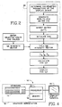
- Fig. 2 illustrates the sequence of steps for transforming any selected color, producible by a CRT color display, into a perceptually uniform color space that is based upon internationally accepted colorimetric standards.
- the perceptually uniform space will hereafter be referred to as the HVC space having coordinates H, V and C, the numerical values of which are described more fully below.
- the display-based HVC space of the present invention can be implemented in any of a variety of graphics display systems such as the 4335 Color Graphics Workstation and the 4235 Graphics Terminal available from Tektronix, Inc. Beaverton, Oregon.
- a graphics display system is shown in the block diagram of Fig. 4.
- the graphics display system 10 includes a workstation 12 comprising input device 14, and a programmable processor 16 with associated memory 18.
- a video monitor or display terminal 20 is associated with the workstation.
- a preliminary step in carrying out the transformation process is to determine the colorimetric parameters of the display device.
- data corresponding to the CRT phosphor characteristics is compiled.
- This data is a tabulation of the luminous intensity levels of the red, green and blue phosphors that correspond to each DAC value.
- DAC values are often defined in one unit increments ranging from 0-255, each DAC value being a numerical representation of the particular electron gun control level for igniting a phosphor.
- the DAC-value/intensity table for the red phosphor describes the intensity level profile for each red electron gun control level.
- the DAC-value/intensity data may be that specified by the CRT manufacturer; however, for applications requiring precise color control it is preferred that the DAC-value/intensity data be measured and periodically updated via suitable spectroradiometric means.
- the DAC-value/intensity tables are normalized to 1 and stored in the memory 18 of the graphics workstation 12.
- the CIE XYZ tristimulus values for each primary phosphor are obtained for a reference white color that is produced by the CRT.
- this tristimulus data is normalized so that the Y tristimulus value of the reference white will equal 1.
- the Y tristimulus value indicates the luminance of the color. Establishing the Y value at 1 will yield a corresponding scaling of the CIELUV metric lightness function L* at a maximum value of 100, which corresponds to the reference white of the display device.
- the tristimulus data is arranged in a RGB-to-XYZ matrix, denoted [A].
- the RGB-to-XYZ matrix elements represent the relative intensity contributions of the red, green and blue phosphors (columns) to the X, Y and Z values (rows) of the reference white.
- the RGB-to-XYZ matrix is next inverted to form an XYZ-to-RGB matrix, denoted [A ⁇ 1], the significance of which is described more fully below.
- V coordinate is determined through use of equations (3) and (4), substituting V for L*.
- the H coordinate of the HVC space generally corresponds to the CIELUV hue angle and is assigned a range of integer values from 0 to 359 corresponding to 1° counterclockwise angular increments in the CIELUV u*v* plane.
- the vertex of the hue angle is aligned with the V axis.
- H0 is selected to establish the 0 value or origin of H at the color most commonly associated with the term "red".
- Color-order systems such as the well-known Munsell book of color, employ a collection of physical samples to identify various hues. Color-order systems should not be confused with the CIE color specification system. It is contemplated that the H origin may be established at colors other than red.
- the chroma coordinate C correlates to the gamut of colors that can be produced by the CRT, and is scaled to correspond to the value or V coordinate of the space.
- the CIELUV chroma calculation C* uv is modified by multiplying that chroma by the value coordinate V for the selected color and by a chroma factor C f , which is a function of the maximum obtainable chroma for a given CRT phosphor set.
- the C coordinate defined above provides a more perceptually uniform CRT-based color space than heretofore available and offers greatly enhanced predictability in color selection.
- the C coordinate is numerically scaled from 0 to 100, with 100 equated to the maximum chroma or G level providable by the CRT.
- the scaling is achieved by defining the chroma factor C f as: C f 100/maximum chroma C* uv for CRT (13)
- Multiplying the CIELUV chroma C* uv for a selected color by the chroma factor C f and by the V coordinate of the HVC space enhances the perceptual uniformity of the HVC space so that at any hue H, a change of n units in the C coordinate will produce a perceived color difference substantially equal to the perceived color difference that occurs if the change of n units is made in the V coordinate. Likewise, for any hue H, a change of n units in the V coordinate will produce a perceived color difference substantially equal to the perceived color difference that occurs if the change of n units is made in the C coordinate.
- the u* and v* coordinates of the red, green and blue phosphor vertices are computed.
- a phosphor vertex is the point in the color space corresponding to the full intensity of one phosphor with the intensities of the remaining phosphors being zero.
- the red phosphor vertex has the greatest C* uv level. The following calculation of the red phosphor vertex is provided to illustrate how all phosphor vertices are calculated.
- red-rgb matrix The calculation of the red vertex involves creation of a single column, three-row, red-rgb matrix, denoted [r].
- the red-rgb matrix elements represent the full intensity DAC value (normalized to 1) for the red phosphor, and 0 DAC values for the green and blue phosphors.
- Multiplication of the red-rgb matrix by the RGB-to-XYZ matrix [A] yields a red-XYZ matrix [R], the elements of which are the tristimulus values X r , Y r , Z r resulting from the full intensity red phosphor.
- the CIE uniform chromaticity coordinates u′, v′ are next calculated for each vertex using equations (I) and (2).
- the u′ n and v′ n pair for the reference white is then calculated based on the previously-determined XYZ values of the reference white.
- the lightness function L* is calculated for each vertex.
- the CIELUV chroma is then calculated according equation (8).
- the maximum CIELUV chroma C* uv of all vertices is then selected and used in equation (12) to determine the chroma factor C f .
- a color is selected by providing the data designating the red, green and blue phosphor intensity combination that would yield the desired color.
- the DAC values of the video RGB system are typically used for such a designation.
- the DAC values are provided to the workstation processor 14 by any of a variety of input devices such as the depicted keyboard 16.
- the DAC values of the selected color form a 3-element rgb intensity vector. Each element of the vector denotes to the relative intensity contribution of each phosphor in creating the selected color.
- the rgb intensity vector is next multiplied by the above-described RGB-to-XYZ matrix [A] to yield the CIE tristimulus values X s , Y s , Z s , for the selected color.
- the X s , Y s , Z s , values are then converted into the HVC coordinates as described above with reference to equations (10), (11) and (12).
- the coordinates of the HVC space are then displayed on a display terminal 20, or otherwise made available for reference by the user.
- the corresponding CIE colorimetric parameters x, y and Y are also provided to the user to permit specification of the selected color in accordance with those internationally accepted standards.
- the H, V and C coordinates of the selected color are entered into the processor 16 of the graphics workstation 12 by a suitable input device such as the depicted keyboard 14.
- the selected X s Y s Z s tristimulus values are next multiplied by the XYZ-to-RGB matrix [A ⁇ 1] to obtain the corresponding rgb intensity vector.
- the rgb intensity vector is converted to DAC values by reference to the stored DAC-value/intensity tables.
- the DAC values corresponding to the selected color are applied to conventional digital-to-analog converters, corrected for gamma, and fed to the electron guns for displaying the selected color on the CRT display.
- the HVC space can be implemented with any color display device having any number of primaries for producing a color.
- a fourth primary such as yellow
- a fourth primary such as yellow
- the calculations described above are readily adaptable to incorporate any number of primaries.
Abstract
Description
- This invention pertains to color display devices, and particularly to a system for reversibly transforming any of the gamut of colors of a display device into a perceptually uniform color space that is based upon internationally accepted colorimetric parameters.
- The accurate control and specification of color in color display devices is important to those who utilize color displays. Part of the effort to meet these control and specification needs has been the development of color spaces that describe, in some useful way, the gamut of colors that can be produced by the particular display device. The coordinates of the color space are made available to the user for selection of the coordinates that correspond to a particular color.
- One widely used color space, known as the video RGB color system, is employed with a cathode-ray tube (CRT) color display. The video RGB color system is directly related to the hardware of the CRT display, namely, the three electron guns that are used to address the three primary color phosphors ("primaries") carried on the CRT screen. The three primary phosphors emit red, green and blue light, respectively. A CRT display is an additive color system and a gamut of colors can be created by controlling the various intensities of the red, green and blue light emitted by the phosphors. The intensities of the phosphors are controlled by altering the beam current of the corresponding electron gun.
- The video RGB color system is represented as a cube-shaped color space having a black point at one corner and a white point at the diagonally opposing corner. The black point corresponds to the absence of emissions from all three phosphors; the white point being the combined full intensity of all three phosphors as excited by the three electron guns. Emanating from the black point in a mutually orthogonal relationship (i.e., in a cartesian coordinate system) are three axes respectively corresponding to the red, green and blue phosphor intensities. Each axis terminates at the full intensity of the associated phosphor. Each axis carries coordinates commonly referred to as "DAC values", which are numerical values corresponding to the electron gun control level required to drive the associated phosphor at a particular intensity. DAC values can be specified to generate any color of the space.
- The video RGB system is widely used because it is based upon the hardware (electron guns and associated drive circuitry) employed for creating the color display. However, it is important to note that the video RGB system does not provide perceptually uniform color space. That is, at various locations within the space, a selected change in the DAC values will not necessarily result in a commensurate perceived change in the displayed color. For example, changing the DAC values to move n units in one region of the space may result in no perceived color change, while a move of n units in another region of the space may yield a substantial perceived change. The perceptual nonuniformity of the video RGB system is a result of the nonlinearity of human vision in perceiving the color spectrum. The effect of the perceptual nonuniformity of the video RGB system is that it is difficult for the user to predict what color will appear for any given change in DAC values.
- In the past, numerous efforts have been made to develop useful perceptually uniform color spaces for facilitating color specification tasks. Many efforts to develop perceptually uniform color spaces have also been directed to correlating the color spaces to internationally accepted standards for color measurement so that the color can be accurately communicated and consistently reproduced. The most prominent international standards for color measurement are collectively termed the CIE system (Commission International de l'Eclairage or International Commission on Illumination).
- The CIE system is based on the premise that specific perceived colors result from the proper combination of an illuminant or reference light source, an object, and an observer. A useful explanation of the CIE system is provided in "Principles of Color Technology", 2nd ed. 1981, by Billmeyer & Saltzman. Generally, the CIE system defines standard light sources having a characteristic spectral power distribution curve. That curve is a depiction of the relative luminous power of the source, i.e., the amount of light associated with each wavelength of the visible spectrum. The CIE system also defines a "standard observer" in terms of three color matching functions. In graphical form, the color matching functions are the relative magnitudes of three standard stimuli necessary to produce any color. Any object, the color of which is to be specified, has a characteristic spectral reflectance curve. The reflectance curve is a representation of the fraction of the light reflected from the object at each wavelength. As is known, the product of the spectral power distribution curve for a standard source and the reflectance curve of the object under study, when separately multiplied by each color matching function will, after suitable normalization, yield three curves, the area under each curve corresponding respectively to the CIE tristimulus values XYZ. The values of the standard stimuli that define the color matching functions are such that the color matching function corresponding to the Y tristimulus value represents the human eye response to the total power of the light (i.e., luminance) reaching the eye. Accordingly, the tristimulus value Y provides an indication of the luminance of the color.
- The CIE tristimulus values have been converted to a two-dimensional map of colors known as the 1931 CIE chromaticity diagram. The 1931 diagram is shown in Fig. 1 and includes a horseshoe-shaped spectrum locus with the spectral colors identified on the locus by their wavelengths. The coordinates of the chromaticity diagram are known as chromaticity coordinates x and y, and are derived by taking the ratios of the respective X and Y tristimulus values to the sum of all three tristimulus values X, Y and Z. The x and y chromaticity coordinates for any real color are located within the bounds of the spectrum locus and the line that joins the ends of the spectrum locus.
- The x and y coordinates do not completely describe a color because they contain no information on the inherent luminance of a color. As noted, the Y component of the tristimulus values is a measure of the luminance of the color. Accordingly, a three-dimensional color specification system is created by adding a third axis to the 1931 diagram which extends upwardly from the xy plane at the x and y coordinates of the source light. The third axis is the Y axis and is scaled in units of luminance. For scaling purposes, it is conventional to normalize the Y values from 0 to 1, representing the full range from black to white, respectively. At each level of luminance the area of the 1931 diagram, which represents the range of colors that can occur, becomes smaller for increasing values of Y and terminates at a single "white point" at the maximum Y value.
- The three-dimensional color specification system just described is known as the CIExyY system. In view of the above, it can be appreciated that any real color can be specified in terms of the CIExyY color specification system and directly related to the particular CIE tristimulus values XYZ. The CIExyY system, which is based upon the 1931 CIE chromaticity diagram (and related tristimulus values XYZ), is a widely accepted method for specifying color. Further, the 1931 diagram or, more typically, data derived therefrom, is valuable because it can be used to predict the additive mixture of two or more colors. That is, tristimulus values of component colors mathematically add to yield the tristimulus values of the resulting mixed color.
- Efforts have been made to transform the CIE color specification system into perceptually uniform color spaces, while preserving the additive mixing feature of the 1931 CIE chromaticity diagram.
- One such transformation of the 1931 diagram includes a two dimensional uniform chromaticity diagram (known as the CIE 1976 UCS diagram) having u′ and v′ coordinates that approximate a perceptually uniform color plane. The coordinates are known as the uniform chromaticity coordinates and are directly related to the x and y chromaticity coordinates (hence, to the XYZ tristimulus values) as follows:
u′ = 4x/(-2x+12y+3) = 4X/(X+15Y-3Z) (1)
v′ = 9y/(-2x+12y+3) = 9Y/(X+15Y-3Z) (2) - As described, in the referenced text by Billmeyer & Saltzman, the 1976 UGS diagram defined by the u′and v′ coordinates has been mathematically converted into a color space that closely approaches perceptual uniformity and is known as the CIELUV color space.
- The CIELUV space is characterized by u*,v* coordinate axes. These axes were defined with the achromatic colors at the origin (u*=0,v*=0) by subtracting the uniform chromaticity values u′n and v′n for the source light from those of the selected color.
- The third coordinate of the CIELUV space, L*, known as the metric lightness function, lies perpendicular to the u*v* plane and intersects that plane at the origin. The L* axis is the axis of the achromatic colors (black, grey and white) and denotes variations in the lightness from L* = 0 (black) to L* = 100 (white).
- As noted, all of the coordinates of the CIELUV space are directly related, via the CIExyY system to the CIE tristimulus values. These relationships are defined below:
L* = 116 (Y/Yn)1/3 - 16; for Y/Yn > 0.008856 (3)
L* = 903.3 (Y/Yn); for Y/Yn ≦ 0.008856 (4)
where
Y = tristimulus value (luminance) of a color, and
Yn = luminance of the reference light source
u* = 13 L* (u′-u′n) (5)
v* = 13 L* (v′-v′n) (6)
where
u′n and v′n are the uniform chromaticity coordinates for the reference light source. - The modified cube-root function for L* as shown above, yields a perceptually uniform scaling of lightness. It is common to refer to the visual sensation of lightness as value.
- Hue is defined in the CIELUV color space as the angle made relative to the positive u* axis. The hue angle, h*, is defined as follows:
h* = arctan (v*/u*) (7) - A third notation, known as the psychometric chroma C*uv, is adopted in conjunction with the CIELUV color space as a numerical representation of the chroma of a color. Chroma describes the saturation or vibrancy of a color, which is its distance from the L* axis at a particular level of lightness or value. Accordingly, the notation C*uv relates to the u*, v* coordinates, as follows:
C*uv = (u*² + v*²)1/2 (8) - The CIELUV space is the most nearly perceptually uniform space developed thus far. Particularly, away from the boundaries of the space, equal physical distances along any given dimension of hue, lightness, or chroma are representative of substantially uniform perceived color differences. As an example, it is convenient to examine a circle of hues taken at a constant level of lightness and chroma. Color pairs sampled from this hue circle, that are 5° apart from one another will be perceived as having the same magnitude of color difference, regardless of the hue family or overall position in the color space. The color difference, ΔE uv, can be quantified in terms of the CIELUV coordinates as follows:
ΔE uv = [(ΔL*)² + (Δv*)² + (Δu*)²]1/2 (9)
wherein the values ΔL*, Δu* and Δv* represent the magnitude of the differences between those coordinates for the color pair. - It can be appreciated that the theoretical advantages of the CIELUV system can be effectively exploited by one interested in specifying a color from it if there is provided a useful method for reversibly transforming conventional color space coordinates, such as the video RGB system coordinates, into the CIELUV coordinates. Further, it has been found that for colors displayed by a CRT, modification of the CIELUV color space is desirable to produce a new color space with enhanced perceptual uniformity, and which is defined by the actual gamut of colors that can be produced by the CRT.
- This invention is directed to a method for reversibly transforming a color, which is selected from the gamut of colors producible by the primaries of a color display device, into a perceptually uniform color space, the coordinates of the space being readily convertible into internationally accepted standards for color measurement. To this end, a new perceptually uniform color space having H, V and C coordinates is defined.
- The new color space, referred to as the HVC space, is constructed to provide enhanced perceptual uniformity over prior color spaces. The H and V coordinates substantially correspond to the CIELUV hue angle and metric lightness function, respectively. However, the coordinate C, representing the chroma of the color, comprises a substantially modified version of the CIELUV chroma coordinate C*uv. It has been found that the HVC color space exhibits greatly improved perceptual uniformity over the CIELUV space because the coordinate C is scaled to correspond to the metric lightness function L* of the CIELUV space, and further adjusted with a chroma factor Cf, which defines the boundaries of the C coordinate within the maximum achievable chroma values of the CRT. The V and C coordinates are so related that a change of n units in the V coordinate will produce a perceived color difference substantially equal to the difference resulting from a change of n units made in the C coordinate and vice versa. As a result, the HVC space offers enhanced predictability for color selection.
- In view of the above, there is provided a method for transforming into the HVC color space any color selected from the color gamut of a display device, wherein the selected color is definable by a primary intensity vector comprising relative luminous intensity values of each of the display primaries. The method includes generating a matrix for converting primary intensity vectors into corresponding XYZ tristimulus values, and multiplying the primary intensity vector of the selected color by the matrix to yield the tristimulus values Xs, Ys and Zs of the selected color. Next computed are the L*, u* and v* coordinates of the CIELUV system corresponding to the Xs, Ys and Zs tristimulus values. The selected point is then transformed into the perceptually uniform color space coordinates H, V and C described above. The Xs, Ys and Zs values are also used to calculate the corresponding CIExyY coordinates for specification of the selected color in terms of those internationally accepted color measurement standards.
- As another aspect of this invention, a method is provided for transforming the H, V and C coordinates of a selected color, into the corresponding primary intensity vector of the selected color.
-
- Fig. 1 is the 1931 CIE chromaticity diagram.
- Fig. 2 is a flow chart illustrating the implementation of the HVC color space and the transformation of the primary intensity vector of a selected color into the coordinates of the HVC space.
- Fig. 3 is a flow chart illustrating the transformation of the H, V and C coordinates of the selected color to a corresponding primary intensity vector.
- Fig. 4 is a block diagram of a graphics workstation and display terminal useful for implementation and manipulation of the HVC color space.
- Fig. 5 is a representation of an HVC color space for a particular CRT display device.
- Fig. 2 illustrates the sequence of steps for transforming any selected color, producible by a CRT color display, into a perceptually uniform color space that is based upon internationally accepted colorimetric standards. The perceptually uniform space will hereafter be referred to as the HVC space having coordinates H, V and C, the numerical values of which are described more fully below. The display-based HVC space of the present invention can be implemented in any of a variety of graphics display systems such as the 4335 Color Graphics Workstation and the 4235 Graphics Terminal available from Tektronix, Inc. Beaverton, Oregon. A graphics display system is shown in the block diagram of Fig. 4. Essentially, the
graphics display system 10 includes aworkstation 12 comprisinginput device 14, and aprogrammable processor 16 with associatedmemory 18. A video monitor or display terminal 20 is associated with the workstation. - Referring to Fig. 2, a preliminary step in carrying out the transformation process is to determine the colorimetric parameters of the display device. To this end, data corresponding to the CRT phosphor characteristics is compiled. This data is a tabulation of the luminous intensity levels of the red, green and blue phosphors that correspond to each DAC value. In RGB video space, DAC values are often defined in one unit increments ranging from 0-255, each DAC value being a numerical representation of the particular electron gun control level for igniting a phosphor. Thus, for example, the DAC-value/intensity table for the red phosphor describes the intensity level profile for each red electron gun control level. The DAC-value/intensity data may be that specified by the CRT manufacturer; however, for applications requiring precise color control it is preferred that the DAC-value/intensity data be measured and periodically updated via suitable spectroradiometric means.
- The DAC-value/intensity tables are normalized to 1 and stored in the
memory 18 of thegraphics workstation 12. - In addition to the DAC-value/intensity data, the CIE XYZ tristimulus values for each primary phosphor are obtained for a reference white color that is produced by the CRT. Preferably, this tristimulus data is normalized so that the Y tristimulus value of the reference white will equal 1. As noted, the Y tristimulus value indicates the luminance of the color. Establishing the Y value at 1 will yield a corresponding scaling of the CIELUV metric lightness function L* at a maximum value of 100, which corresponds to the reference white of the display device.
- Once normalized, the tristimulus data is arranged in a RGB-to-XYZ matrix, denoted [A]. The RGB-to-XYZ matrix elements represent the relative intensity contributions of the red, green and blue phosphors (columns) to the X, Y and Z values (rows) of the reference white.
- The RGB-to-XYZ matrix is next inverted to form an XYZ-to-RGB matrix, denoted [A⁻¹], the significance of which is described more fully below.
- With continued reference to Fig. 2, the HVC space is next initialized. That is, the constants and functions for defining the H, V and C coordinates of the HVC space are established for the particular CRT. Specifically, with reference to Fig. 5, the vertical axis, V, of the HVC space is defined as corresponding to the CIELUV metric lightness function L* or
V = L* (10) - Accordingly, for any selected color producible by the CRT, upon determination of the corresponding tristimulus value Y, the V coordinate is determined through use of equations (3) and (4), substituting V for L*.
- The H coordinate of the HVC space generally corresponds to the CIELUV hue angle and is assigned a range of integer values from 0 to 359 corresponding to 1° counterclockwise angular increments in the CIELUV u*v* plane. The vertex of the hue angle is aligned with the V axis. The H coordinate is the integer value of the hue angle and is calculated as:
H = (arctan (v*/u*) + K)-H₀ (11)
where
K = 0° for u* > 0° and v* > 0;
K = 90° for u* < 0 and v* > 0;
K = 180° for u* < 0 and v* < 0;
K = 270° for u* > 0 and v* < 0; - The constant H₀ is selected to establish the 0 value or origin of H at the color most commonly associated with the term "red". In this regard, establishing H= 0 at approximately -13°, plus or minus 2°, relative to the positive u* axis of the CIELUV color system corresponds to the hue angle of a red that conforms in name to many conventional color- order systems. Color-order systems such as the well-known Munsell book of color, employ a collection of physical samples to identify various hues. Color-order systems should not be confused with the CIE color specification system. It is contemplated that the H origin may be established at colors other than red.
- In view of the above, it can be appreciated that for any selected color producible by the CRT, upon determination of the corresponding tristimulus values XYZ, and transformation of those values into the CIELUV L*, u* and v* coordinates via equations (5) and (6), the H coordinate of the HVC space can be computed with equation (11).
- An important aspect of the HVC space is that the chroma coordinate C correlates to the gamut of colors that can be produced by the CRT, and is scaled to correspond to the value or V coordinate of the space. In short, the CIELUV chroma calculation C*uv is modified by multiplying that chroma by the value coordinate V for the selected color and by a chroma factor Cf, which is a function of the maximum obtainable chroma for a given CRT phosphor set.
- Accordingly, the C coordinate is calculated as:
C = C*uv(V) (Cf) (12) - It has been found that the C coordinate defined above provides a more perceptually uniform CRT-based color space than heretofore available and offers greatly enhanced predictability in color selection. In this regard the C coordinate is numerically scaled from 0 to 100, with 100 equated to the maximum chroma or G level providable by the CRT. The scaling is achieved by defining the chroma factor Cf as:
C f 100/maximum chroma C*uv for CRT (13) - Multiplying the CIELUV chroma C*uv for a selected color by the chroma factor Cf and by the V coordinate of the HVC space enhances the perceptual uniformity of the HVC space so that at any hue H, a change of n units in the C coordinate will produce a perceived color difference substantially equal to the perceived color difference that occurs if the change of n units is made in the V coordinate. Likewise, for any hue H, a change of n units in the V coordinate will produce a perceived color difference substantially equal to the perceived color difference that occurs if the change of n units is made in the C coordinate.
- To determine the maximum chroma C*uv producible by the CRT (and thereafter calculate the chroma factor Cf) the u* and v* coordinates of the red, green and blue phosphor vertices are computed. A phosphor vertex is the point in the color space corresponding to the full intensity of one phosphor with the intensities of the remaining phosphors being zero. Typically the red phosphor vertex has the greatest C*uv level. The following calculation of the red phosphor vertex is provided to illustrate how all phosphor vertices are calculated.
- The calculation of the red vertex involves creation of a single column, three-row, red-rgb matrix, denoted [r]. The red-rgb matrix elements represent the full intensity DAC value (normalized to 1) for the red phosphor, and 0 DAC values for the green and blue phosphors. Multiplication of the red-rgb matrix by the RGB-to-XYZ matrix [A] yields a red-XYZ matrix [R], the elements of which are the tristimulus values Xr, Yr, Zr resulting from the full intensity red phosphor. In equation form:

- Employing similar notation for the green and blue phosphors yields:

- The CIE uniform chromaticity coordinates u′, v′ are next calculated for each vertex using equations (I) and (2). The u′n and v′n pair for the reference white is then calculated based on the previously-determined XYZ values of the reference white. Finally, the lightness function L* is calculated for each vertex. By way of example, the lightness L* of the red vertex is determined by multiplying the RGB-to-XYZ matrix by the Yr row of the red-XYZ matrix to yield the Yvr tristimulus value corresponding to the red vertex or:
Yvr = [A]Yr - Incorporating Yvr into equations (3) and (4) yields the value of the metric lightness function L*vr of the red vertex. Similar calculations yield L*gr and L*br values for the green and blue phosphor vertices respectively.
- Given the above values of u′, v′, u′n, V′n and L* for each phosphor vertex, the u* and v* coordinates for each vertex are then calculated using equations (5) and (6).
- For each phosphor vertex, the CIELUV chroma is then calculated according equation (8). The maximum CIELUV chroma C*uv of all vertices is then selected and used in equation (12) to determine the chroma factor Cf.
- With the HVC space initialized as just described, this discussion now turns to the method for transforming a color selected from a gamut of colors producible by a CRT display device into the coordinates of the HVC space. First, a color is selected by providing the data designating the red, green and blue phosphor intensity combination that would yield the desired color. As noted earlier, the DAC values of the video RGB system are typically used for such a designation. The DAC values are provided to the
workstation processor 14 by any of a variety of input devices such as the depictedkeyboard 16. - The DAC values of the selected color form a 3-element rgb intensity vector. Each element of the vector denotes to the relative intensity contribution of each phosphor in creating the selected color. The rgb intensity vector is next multiplied by the above-described RGB-to-XYZ matrix [A] to yield the CIE tristimulus values Xs, Ys, Zs, for the selected color. The Xs, Ys, Zs, values are then converted into the HVC coordinates as described above with reference to equations (10), (11) and (12). Preferably, the coordinates of the HVC space are then displayed on a
display terminal 20, or otherwise made available for reference by the user. Further, the corresponding CIE colorimetric parameters x, y and Y are also provided to the user to permit specification of the selected color in accordance with those internationally accepted standards. - Referring to Fig. 3, now discussed is the method for transforming the H, V and C coordinates of a selected color to the corresponding rgb intensity vector employed for displaying the selected color on the CRT display device.
- The implementation steps described above and shown as
block 22 in Figs. 2 and 3 are performed in the present transformation. In this regard, it is noteworthy that the implementation steps need only be undertaken once for each display device although greater precision is possible if the colorimetric parameters of the device are frequently recalibrated. - The H, V and C coordinates of the selected color are entered into the
processor 16 of thegraphics workstation 12 by a suitable input device such as the depictedkeyboard 14. The V coordinate is immediately checked to determine if the black point has been selected (i.e., lightness or "value" V = 0). If the black point has been selected, an appropriate rgb intensity vector is generated (i.e., all elements = 0) and supplied to the CRT display device to display the black color as described more fully below. - If the black point is not selected, the tristimulus value Ys is calculated for the selected point. In this regard, it is noted that upon review of equations (3) and (4), it is clear that equation (3) is solved for Y s if the selected V coordinate is less than 8 (recalling that V = L*) otherwise equation (4) is employed.
- The uniform chromaticity coordinates u′s v′s are next calculated for the selected color. To this end, the distance from the known reference white point u′n and v′n is determined. This distance, D, is the CIELUV C*uv level. Accordingly the distance D = C/((Cf) (V)).
- The u′ axis component and v′ axis component of the distance, D, is then calculated using the hue angle, which, as seen in equations (7) and (11), is the sum of the selected coordinate H and H₀. Accordingly, the u′s v′s coordinates of the selected point are calculated as follows:
u′s = u′n + D (cos (H + H₀)) (17)
v′s = v′n + D (sin (H + H₀)) (18) - The u′s, v′s coordinates of the selected point are then employed to determine the tristimulus values of the selected point. Specifically, the values x and y are calculated using equations (1) and (2) and the calculated values of u′s and v′s.
Further, the z chromaticity coordinate is determined as
z = 1.0 - x - y. (19) - With the selected Ys as calculated above,
Xs = x (Ys/Y) and (20)
Zs = z (Ys/Y). (21) - As indicated in Fig. 3, the selected Xs Ys Zs tristimulus values are next multiplied by the XYZ-to-RGB matrix [A⁻¹] to obtain the corresponding rgb intensity vector.
- The rgb intensity vector is converted to DAC values by reference to the stored DAC-value/intensity tables. The DAC values corresponding to the selected color are applied to conventional digital-to-analog converters, corrected for gamma, and fed to the electron guns for displaying the selected color on the CRT display.
- While a preferred embodiment of the invention has been illustrated and described, it will be appreciated that various changes can be made therein without departing from the spirit and scope of the invention. In this regard, it is contemplated that the HVC space can be implemented with any color display device having any number of primaries for producing a color. For example, a fourth primary, such as yellow, may be employed with certain flat panel-type display devices. The calculations described above are readily adaptable to incorporate any number of primaries.
Claims (13)
H = arctan (v*/u*) + K,
where
K = 0° for u* > 0 and v* > 0;
K = 90° for u* < 0 and v* > 0;
K = 180° for u* < 0 and v* < 0;
K = 270° for u* > 0 and v* < 0;
V = L*;
C = C*uv(V) (Cf).
H = arctan (v*/u*) + K,
where
K = 0° for u* > 0 and v* > 0;
K = 90° for u* < 0 and v* > 0;
K = 180° for u* < 0 and v* < 0;
K = 270° for u* > 0 and v* < 0;
V = L*; and
C = (v*² + u*²)1/2 (V) (Cf)
wherein Cf is a factor for establishing a maximum numerical value for C producible by the display device.
H = arctan (v*/u*) + K)-H₀,
where
K = 0° for u* > 0 and v* > 0;
K = 90° for u* < 0 and v* > 0;
K = 180° for u* < 0 and v* < 0;
K = 270° for u* > 0 and v* < 0;
-11° ≦ H₀ ≦ -15°
V = L*
C = (v*²+u*²)1/2(V) (Cf) wherein Cf is a factor for establishing a maximum numerical value for C producible by the display device,
into the corresponding primary luminous intensity levels of a display device having a plurality of primaries, the method comprising the steps of:
H = arctan (v*/u*) + K)-H₀,
where
K = 0° for u* > 0 and v* > 0;
K = 90° for u* < 0 and v* > 0;
K = 180° for u* < 0 and v* < 0;
K = 270° for u* > 0 and v* < 0;
-11° ≦ H₀ ≦ -15°
V = L*
C = (v*²+u*²)1/2(V) (Cf) wherein Cf is a factor for establishing a maximum numerical value for C producible by the display device,
into the corresponding primary intensity levels of a CRT display device having red, green and blue primaries, the method comprising the steps of:
(1) generating a matrix for converting primary intensity vectors into corresponding XYZ tristimulus values;
(2) multiplying the primary intensity vector of the selected color by the matrix to yield the tristimulus values Xs, Ys, Zs of the selected color;
(3) determining the L*, u* and v* coordinates of the CIELUV system that correspond to the tristimulus values Xs, Ys and Zs; and
(4) computing the H, V and C coordinates as:
H = arctan (v*/u*) + K)-H₀,
where
K = 0° for u* > 0 and v* > 0;
K = 90° for u* < 0 and v* > 0;
K = 180° for u* < 0 and v* < 0;
K = 270° for u* > 0 and v* < 0;
-11° ≦ H₀ ≦ -15°
H = arctan (v*/u*) + K)-H₀,
where
K = 0° for u* > 0 and v* > 0;
K = 90° for u* < 0 and v* > 0;
K = 180° for u* < 0 and v* < 0;
K = 270° for u* > 0 and v* < 0;
-11° ≦ H₀ ≦ -15°
V = L*
C = (v*²+u*²)1/2(V) (Cf) wherein Cf is a factor for establishing a maximum numerical value for C producible by the display device,
into the corresponding primary intensity levels of a display device having a plurality of primaries, the apparatus comprising:
(1) converting the H, V and C coordinates of the selected color into a tristimulus vector denoting tristimulus values Xs, Ys, and Zs corresponding to the selected color;
(2) generating a matrix for converting tristimulus vectors into corresponding primary intensity vectors that denote relative intensity levels of the display device primaries; and
(3) multiplying the tristimulus vector of the selected color by the matrix to convert the tristimulus vector of the selected color into a selected primary intensity vector, the selected primary intensity vector denoting the relative luminous levels of the primaries for displaying the selected color on the display device.
Applications Claiming Priority (2)
| Application Number | Priority Date | Filing Date | Title |
|---|---|---|---|
| US113029 | 1987-10-26 | ||
| US07/113,029 US4843573A (en) | 1987-10-26 | 1987-10-26 | Display-based color system |
Publications (3)
| Publication Number | Publication Date |
|---|---|
| EP0313794A2 true EP0313794A2 (en) | 1989-05-03 |
| EP0313794A3 EP0313794A3 (en) | 1991-01-23 |
| EP0313794B1 EP0313794B1 (en) | 1993-10-27 |
Family
ID=22347217
Family Applications (1)
| Application Number | Title | Priority Date | Filing Date |
|---|---|---|---|
| EP88115229A Expired - Lifetime EP0313794B1 (en) | 1987-10-26 | 1988-09-16 | Display-based color system |
Country Status (4)
| Country | Link |
|---|---|
| US (1) | US4843573A (en) |
| EP (1) | EP0313794B1 (en) |
| JP (1) | JPH01147989A (en) |
| DE (1) | DE3885231T2 (en) |
Cited By (4)
| Publication number | Priority date | Publication date | Assignee | Title |
|---|---|---|---|---|
| EP0448330A1 (en) * | 1990-03-19 | 1991-09-25 | Canon Kabushiki Kaisha | Method and apparatus for processing image |
| WO1992003855A2 (en) * | 1990-08-23 | 1992-03-05 | Schlumberger Technology Corporation | System and method of selecting the reproducible colors in a discrete reproduction system |
| WO1994030003A1 (en) * | 1993-06-16 | 1994-12-22 | Taligent, Inc. | Color matching system |
| FR2819620A1 (en) * | 2001-01-17 | 2002-07-19 | Mitsubishi Electric Corp | Method for determining color conversion characteristic for an image display device, particularly for use with a monitoring device where color output must conform to a standard, having faster conversion characteristic determination |
Families Citing this family (57)
| Publication number | Priority date | Publication date | Assignee | Title |
|---|---|---|---|---|
| US5334992A (en) * | 1987-10-26 | 1994-08-02 | Tektronix, Inc. | Computer display color control and selection system |
| US4875032A (en) * | 1987-10-26 | 1989-10-17 | Mcmanus Paul A | Method and apparatus for processing colorimetric parameters of a color sample |
| GB8800503D0 (en) * | 1988-01-11 | 1988-02-10 | Crosfield Electronics Ltd | Apparatus for generating two-dimensional coloured display |
| JPH0264875A (en) * | 1988-08-31 | 1990-03-05 | Toshiba Corp | High speed chroma converter for color picture |
| US5130701A (en) * | 1989-05-12 | 1992-07-14 | The United States Of America As Represented By The United States Department Of Energy | Digital color representation |
| US5254977A (en) * | 1989-06-12 | 1993-10-19 | Crosfield Electronics Ltd. | Color display |
| US5053861A (en) * | 1989-07-24 | 1991-10-01 | Eastman Kodak Company | Compression method and apparatus for single-sensor color imaging systems |
| US4949135A (en) * | 1989-08-17 | 1990-08-14 | Eastman Kodak Company | Visual based process control apparatus which is based on a near uniform human visual response space |
| GB9005030D0 (en) * | 1990-03-06 | 1990-05-02 | Crosfield Electronics Ltd | Image data processing |
| US5798262A (en) * | 1991-02-22 | 1998-08-25 | Applied Spectral Imaging Ltd. | Method for chromosomes classification |
| US5243414A (en) * | 1991-07-29 | 1993-09-07 | Tektronix, Inc. | Color processing system |
| US5295202A (en) * | 1991-08-19 | 1994-03-15 | Eastman Kodak Company | Method and apparatus for replicating a two-color original image with foreground and background colors exchanged |
| US5909291A (en) * | 1992-03-19 | 1999-06-01 | Apple Computer, Inc. | Color matching apparatus and method |
| US5963201A (en) * | 1992-05-11 | 1999-10-05 | Apple Computer, Inc. | Color processing system |
| JP3158654B2 (en) * | 1992-05-19 | 2001-04-23 | ミノルタ株式会社 | Digital color image forming device |
| US6081254A (en) * | 1993-08-12 | 2000-06-27 | Hitachi, Ltd. | Color correction system of imaging apparatus |
| US5631749A (en) * | 1995-01-12 | 1997-05-20 | Brother Kogyo Kabushiki Kaisha | Color image signal processing device |
| WO1997028640A1 (en) * | 1996-02-02 | 1997-08-07 | Light Source Computer Images, Inc. | Appearance-based technique for rendering colors on an output device |
| US5650942A (en) * | 1996-02-02 | 1997-07-22 | Light Source Computer Images, Inc. | Appearance-based technique for rendering colors on an output device |
| US5809213A (en) * | 1996-02-23 | 1998-09-15 | Seiko Epson Corporation | Automatic color calibration of a color reproduction system |
| US7728845B2 (en) * | 1996-02-26 | 2010-06-01 | Rah Color Technologies Llc | Color calibration of color image rendering devices |
| US6043909A (en) | 1996-02-26 | 2000-03-28 | Imagicolor Corporation | System for distributing and controlling color reproduction at multiple sites |
| US5798767A (en) * | 1996-03-15 | 1998-08-25 | Rendition, Inc. | Method and apparatus for performing color space conversion using blend logic |
| US6243059B1 (en) * | 1996-05-14 | 2001-06-05 | Rainbow Displays Inc. | Color correction methods for electronic displays |
| US6134029A (en) * | 1996-09-09 | 2000-10-17 | Light Source Acquisition Company | Scanner calibration technique |
| US6081276A (en) * | 1996-11-14 | 2000-06-27 | International Business Machines Corporation | Method and apparatus for creating a color name dictionary and for querying an image by color name |
| WO1999010866A1 (en) | 1997-08-25 | 1999-03-04 | Imagicolor Corp | A system for distributing and controlling color reproduction at multiple sites |
| US6005968A (en) * | 1997-08-29 | 1999-12-21 | X-Rite, Incorporated | Scanner calibration and correction techniques using scaled lightness values |
| US6862029B1 (en) * | 1999-07-27 | 2005-03-01 | Hewlett-Packard Development Company, L.P. | Color display system |
| US7102648B1 (en) | 2000-04-11 | 2006-09-05 | Rah Color Technologies Llc | Methods and apparatus for calibrating a color display |
| US6870523B1 (en) | 2000-06-07 | 2005-03-22 | Genoa Color Technologies | Device, system and method for electronic true color display |
| US7352488B2 (en) * | 2000-12-18 | 2008-04-01 | Genoa Color Technologies Ltd | Spectrally matched print proofer |
| EP1430385B1 (en) * | 2001-01-10 | 2017-03-29 | X-Rite, Inc. | Harmonizing color selection system and method |
| WO2002099557A2 (en) | 2001-06-07 | 2002-12-12 | Genoa Technologies Ltd. | System and method of data conversion for wide gamut displays |
| US8289266B2 (en) | 2001-06-11 | 2012-10-16 | Genoa Color Technologies Ltd. | Method, device and system for multi-color sequential LCD panel |
| JP4170899B2 (en) * | 2001-06-11 | 2008-10-22 | ゲノア・テクノロジーズ・リミテッド | Apparatus, system and method for color display |
| US7714824B2 (en) * | 2001-06-11 | 2010-05-11 | Genoa Color Technologies Ltd. | Multi-primary display with spectrally adapted back-illumination |
| IL159779A0 (en) * | 2001-07-12 | 2004-06-20 | Genoa Technologies Ltd | Sequential projection color display using multiple imaging panels |
| IL159972A0 (en) * | 2001-07-23 | 2004-06-20 | Genoa Technologies Ltd | System and method for displaying an image |
| IL162831A0 (en) * | 2002-01-07 | 2005-11-20 | Genoa Technologies Ltd | Electronic color display for soft proofing |
| KR100905347B1 (en) * | 2002-02-26 | 2009-07-01 | 유니-픽셀 디스플레이스, 인코포레이티드 | Field sequential color palette enhancement |
| JP4799823B2 (en) * | 2002-04-11 | 2011-10-26 | ジェノア・カラー・テクノロジーズ・リミテッド | Color display apparatus and method for improving attributes |
| US7471822B2 (en) * | 2002-07-24 | 2008-12-30 | Genoa Color Technologies Ltd | Method and apparatus for high brightness wide color gamut display |
| WO2004068460A1 (en) | 2003-01-28 | 2004-08-12 | Koninklijke Philips Electronics N.V. | Optimal subpixel arrangement for displays with more than three primary colors |
| US20040164101A1 (en) * | 2003-02-20 | 2004-08-26 | Valois Sas | Fluid dispenser |
| US7417799B2 (en) * | 2003-08-04 | 2008-08-26 | Genoa Color Technologies Ltd. | Multi-primary color display |
| CN103177701A (en) * | 2003-12-15 | 2013-06-26 | 格诺色彩技术有限公司 | Multi-primary liquid crystal display |
| US7495722B2 (en) | 2003-12-15 | 2009-02-24 | Genoa Color Technologies Ltd. | Multi-color liquid crystal display |
| US20050259109A1 (en) * | 2004-05-19 | 2005-11-24 | Microsoft Corporation | System and method for a gamut mapping platform having plug-in transform functions |
| US7148902B2 (en) * | 2004-10-01 | 2006-12-12 | Canon Kabushiki Kaisha | Color characterization of projectors |
| US8587621B2 (en) * | 2005-11-28 | 2013-11-19 | Genoa Color Technologies Ltd. | Sub-pixel rendering of a multiprimary image |
| US8520936B2 (en) * | 2007-05-02 | 2013-08-27 | The Regents Of The University Of California | Method and apparatus for use of an universal color index (UCI): a color appearance system calibrated to reflectance spectra |
| EP2838320A1 (en) * | 2008-03-11 | 2015-02-18 | Robe Lighting Inc. | A universal color control matrix |
| JP5565139B2 (en) * | 2010-06-28 | 2014-08-06 | セイコーエプソン株式会社 | Image processing apparatus, projection display apparatus, and image processing method |
| JP2014170091A (en) * | 2013-03-04 | 2014-09-18 | Sony Corp | Display device, display driving method, method for manufacturing display device, and electronic apparatus |
| JP6835000B2 (en) | 2018-01-31 | 2021-02-24 | 日亜化学工業株式会社 | Light emitting device and light source |
| CN109614064A (en) * | 2018-12-13 | 2019-04-12 | Oppo广东移动通信有限公司 | A kind of image display method, image display apparatus and terminal device |
Citations (5)
| Publication number | Priority date | Publication date | Assignee | Title |
|---|---|---|---|---|
| DE2906955A1 (en) * | 1978-02-22 | 1979-09-27 | Nissan Motor | METHOD AND DEVICE FOR COLOR REPRODUCTION |
| US4477833A (en) * | 1981-08-12 | 1984-10-16 | R. R. Donnelley & Sons Company | Method of color conversion with improved interpolation |
| US4609916A (en) * | 1983-05-10 | 1986-09-02 | Thomson Csf | Method and device for displaying primary colors utilizing input values representative of brightness, saturation and hue of a colored background |
| US4670780A (en) * | 1985-05-28 | 1987-06-02 | Tektronix, Inc. | Method of matching hardcopy colors to video display colors in which unreachable video display colors are converted into reachable hardcopy colors in a mixture-single-white (MSW) color space |
| US4875032A (en) * | 1987-10-26 | 1989-10-17 | Mcmanus Paul A | Method and apparatus for processing colorimetric parameters of a color sample |
Family Cites Families (6)
| Publication number | Priority date | Publication date | Assignee | Title |
|---|---|---|---|---|
| JPS586353B2 (en) * | 1974-08-26 | 1983-02-04 | 日本放送協会 | color television station |
| DE2844158C3 (en) * | 1978-10-10 | 1981-10-15 | Burda Verwaltungs Kg Schutterwald, 7600 Offenburg | Process for the reproduction of original documents which are scanned for their color content according to a three-range process |
| WO1981001065A1 (en) * | 1979-10-05 | 1981-04-16 | Hell R Gmbh | Process for transforming chrominance numerical signals of an orthogonal system of colour coordinates into numerical colour signals and into saturation signals of a system of colour coordinates and transformation circuit |
| US4500919A (en) * | 1982-05-04 | 1985-02-19 | Massachusetts Institute Of Technology | Color reproduction system |
| JPS62189456A (en) * | 1986-02-17 | 1987-08-19 | Fuji Photo Film Co Ltd | Main picture detection method and photographic printing exposure decision method employing said detection |
| GB8614877D0 (en) * | 1986-06-18 | 1986-07-23 | Rca Corp | Display processors |
-
1987
- 1987-10-26 US US07/113,029 patent/US4843573A/en not_active Expired - Lifetime
-
1988
- 1988-09-16 DE DE88115229T patent/DE3885231T2/en not_active Expired - Fee Related
- 1988-09-16 EP EP88115229A patent/EP0313794B1/en not_active Expired - Lifetime
- 1988-10-25 JP JP63269302A patent/JPH01147989A/en active Granted
Patent Citations (5)
| Publication number | Priority date | Publication date | Assignee | Title |
|---|---|---|---|---|
| DE2906955A1 (en) * | 1978-02-22 | 1979-09-27 | Nissan Motor | METHOD AND DEVICE FOR COLOR REPRODUCTION |
| US4477833A (en) * | 1981-08-12 | 1984-10-16 | R. R. Donnelley & Sons Company | Method of color conversion with improved interpolation |
| US4609916A (en) * | 1983-05-10 | 1986-09-02 | Thomson Csf | Method and device for displaying primary colors utilizing input values representative of brightness, saturation and hue of a colored background |
| US4670780A (en) * | 1985-05-28 | 1987-06-02 | Tektronix, Inc. | Method of matching hardcopy colors to video display colors in which unreachable video display colors are converted into reachable hardcopy colors in a mixture-single-white (MSW) color space |
| US4875032A (en) * | 1987-10-26 | 1989-10-17 | Mcmanus Paul A | Method and apparatus for processing colorimetric parameters of a color sample |
Cited By (7)
| Publication number | Priority date | Publication date | Assignee | Title |
|---|---|---|---|---|
| EP0448330A1 (en) * | 1990-03-19 | 1991-09-25 | Canon Kabushiki Kaisha | Method and apparatus for processing image |
| US5786906A (en) * | 1990-03-19 | 1998-07-28 | Canon Kabushiki Kaisha | Method and apparatus for processing image |
| WO1992003855A2 (en) * | 1990-08-23 | 1992-03-05 | Schlumberger Technology Corporation | System and method of selecting the reproducible colors in a discrete reproduction system |
| WO1992003855A3 (en) * | 1990-08-23 | 1992-04-16 | Schlumberger Technology Corp | System and method of selecting the reproducible colors in a discrete reproduction system |
| US5287122A (en) * | 1990-08-23 | 1994-02-15 | Schlumberger Technology Corporation | System and method of selecting the reproducible colors in a discrete reproduction system |
| WO1994030003A1 (en) * | 1993-06-16 | 1994-12-22 | Taligent, Inc. | Color matching system |
| FR2819620A1 (en) * | 2001-01-17 | 2002-07-19 | Mitsubishi Electric Corp | Method for determining color conversion characteristic for an image display device, particularly for use with a monitoring device where color output must conform to a standard, having faster conversion characteristic determination |
Also Published As
| Publication number | Publication date |
|---|---|
| DE3885231D1 (en) | 1993-12-02 |
| DE3885231T2 (en) | 1994-02-24 |
| JPH0444277B2 (en) | 1992-07-21 |
| EP0313794B1 (en) | 1993-10-27 |
| JPH01147989A (en) | 1989-06-09 |
| US4843573A (en) | 1989-06-27 |
| EP0313794A3 (en) | 1991-01-23 |
Similar Documents
| Publication | Publication Date | Title |
|---|---|---|
| EP0313794B1 (en) | Display-based color system | |
| US4985853A (en) | Display-based color system | |
| EP0313796B1 (en) | Computer display color control and selection system | |
| EP0550212B1 (en) | Method for improved color reproduction | |
| US5311212A (en) | Functional color selection system | |
| US5254978A (en) | Reference color selection system | |
| US7215343B2 (en) | Color correction using a device-dependent display profile | |
| US5243414A (en) | Color processing system | |
| Fairchild et al. | Meet iCAM: A next-generation color appearance model | |
| US7629983B2 (en) | Correction techniques for soft proofing | |
| EP0546773B1 (en) | Graphical user interface for editing a palette of colours | |
| US20070154083A1 (en) | Editing of digital images, including (but not limited to) highlighting and shadowing of image areas | |
| US7486419B2 (en) | Editing (including saturation editing) of digital color images | |
| Masaoka | Display gamut metrology using chromaticity diagram | |
| Fang et al. | 78‐2: A Matrix‐Based Method of Color Correction for Metamerism Failure between LCD and OLED | |
| US20020167527A1 (en) | Process for the production of a color palette | |
| JP3130589B2 (en) | Color arrangement support method and apparatus | |
| Murch et al. | Color in computer graphics: Manipulating and matching color | |
| US20070146831A1 (en) | Editing of digital images, including (but not limited to) color-to-monochromatic conversion and changing the color of a monochromatic image | |
| US7495800B2 (en) | Color coordinate systems including systems with a coordinate defined by a square root of a quadratic polynomial in tristimulus values and, possibly, by a sign of a function of one or more of tristimulus values | |
| Benzschawel | Colorimetry of self-luminous displays | |
| Neri | Color CRT characterization presented solely in terms of the CIE system | |
| Campcanu et al. | Colour monitor calibration based on CIE standards | |
| Laihanen | New approach to the manipulation of color display images | |
| KR20070079220A (en) | Color temperature setting and displaying method |
Legal Events
| Date | Code | Title | Description |
|---|---|---|---|
| PUAI | Public reference made under article 153(3) epc to a published international application that has entered the european phase |
Free format text: ORIGINAL CODE: 0009012 |
|
| AK | Designated contracting states |
Kind code of ref document: A2 Designated state(s): DE FR GB NL |
|
| PUAL | Search report despatched |
Free format text: ORIGINAL CODE: 0009013 |
|
| AK | Designated contracting states |
Kind code of ref document: A3 Designated state(s): DE FR GB NL |
|
| 17P | Request for examination filed |
Effective date: 19910205 |
|
| RAP1 | Party data changed (applicant data changed or rights of an application transferred) |
Owner name: TEKTRONIX, INC. |
|
| 17Q | First examination report despatched |
Effective date: 19921123 |
|
| GRAA | (expected) grant |
Free format text: ORIGINAL CODE: 0009210 |
|
| AK | Designated contracting states |
Kind code of ref document: B1 Designated state(s): DE FR GB NL |
|
| PG25 | Lapsed in a contracting state [announced via postgrant information from national office to epo] |
Ref country code: NL Effective date: 19931027 Ref country code: FR Effective date: 19931027 |
|
| REF | Corresponds to: |
Ref document number: 3885231 Country of ref document: DE Date of ref document: 19931202 |
|
| EN | Fr: translation not filed | ||
| NLV1 | Nl: lapsed or annulled due to failure to fulfill the requirements of art. 29p and 29m of the patents act | ||
| PLBE | No opposition filed within time limit |
Free format text: ORIGINAL CODE: 0009261 |
|
| STAA | Information on the status of an ep patent application or granted ep patent |
Free format text: STATUS: NO OPPOSITION FILED WITHIN TIME LIMIT |
|
| 26N | No opposition filed | ||
| PGFP | Annual fee paid to national office [announced via postgrant information from national office to epo] |
Ref country code: GB Payment date: 19970815 Year of fee payment: 10 |
|
| PGFP | Annual fee paid to national office [announced via postgrant information from national office to epo] |
Ref country code: DE Payment date: 19970818 Year of fee payment: 10 |
|
| PG25 | Lapsed in a contracting state [announced via postgrant information from national office to epo] |
Ref country code: GB Free format text: LAPSE BECAUSE OF NON-PAYMENT OF DUE FEES Effective date: 19980916 |
|
| GBPC | Gb: european patent ceased through non-payment of renewal fee |
Effective date: 19980916 |
|
| PG25 | Lapsed in a contracting state [announced via postgrant information from national office to epo] |
Ref country code: DE Free format text: LAPSE BECAUSE OF NON-PAYMENT OF DUE FEES Effective date: 19990701 |