EP0314608A2 - Method of and apparatus for producing three-dimensional sculpture works on a desired reduced scale - Google Patents
Method of and apparatus for producing three-dimensional sculpture works on a desired reduced scale Download PDFInfo
- Publication number
- EP0314608A2 EP0314608A2 EP88730232A EP88730232A EP0314608A2 EP 0314608 A2 EP0314608 A2 EP 0314608A2 EP 88730232 A EP88730232 A EP 88730232A EP 88730232 A EP88730232 A EP 88730232A EP 0314608 A2 EP0314608 A2 EP 0314608A2
- Authority
- EP
- European Patent Office
- Prior art keywords
- pressure vessel
- adapter piece
- vessel according
- neck
- valve
- Prior art date
- Legal status (The legal status is an assumption and is not a legal conclusion. Google has not performed a legal analysis and makes no representation as to the accuracy of the status listed.)
- Granted
Links
Images


Classifications
-
- G—PHYSICS
- G03—PHOTOGRAPHY; CINEMATOGRAPHY; ANALOGOUS TECHNIQUES USING WAVES OTHER THAN OPTICAL WAVES; ELECTROGRAPHY; HOLOGRAPHY
- G03B—APPARATUS OR ARRANGEMENTS FOR TAKING PHOTOGRAPHS OR FOR PROJECTING OR VIEWING THEM; APPARATUS OR ARRANGEMENTS EMPLOYING ANALOGOUS TECHNIQUES USING WAVES OTHER THAN OPTICAL WAVES; ACCESSORIES THEREFOR
- G03B35/00—Stereoscopic photography
-
- G—PHYSICS
- G03—PHOTOGRAPHY; CINEMATOGRAPHY; ANALOGOUS TECHNIQUES USING WAVES OTHER THAN OPTICAL WAVES; ELECTROGRAPHY; HOLOGRAPHY
- G03C—PHOTOSENSITIVE MATERIALS FOR PHOTOGRAPHIC PURPOSES; PHOTOGRAPHIC PROCESSES, e.g. CINE, X-RAY, COLOUR, STEREO-PHOTOGRAPHIC PROCESSES; AUXILIARY PROCESSES IN PHOTOGRAPHY
- G03C9/00—Stereo-photographic or similar processes
Definitions
- the invention relates to a pressure vessel for storing and removing noble gas, special gas or gas mixtures of high purity according to the preamble of the main claim.
- the object of the invention is to provide a pressure vessel with a connection with improved properties for the storage and removal of noble gases, special gases and gas mixtures of high purity in order to avoid contamination and / or impairment of the mixture constancy of the gases during storage.
- the pressure vessel and the connection should also be suitable for gas pressures up to approx. 200 bar and inexpensive to manufacture.
- the solution to the problem is a pressure vessel with the characterizing features of the main claim.
- the material of the pressure vessel is chemically resistant to a great extent to all gases and gas mixtures under consideration. It also has the property that it can be galvanically mirror-polished (electrochemical polishing), as a result of which the active surface is leveled and considerably reduced compared to the unpolished state. This greatly reduces the absorption effect of the gases on the inner wall of the container and the release of particles. In addition, after electropolishing, the inner surface is free of residual mechanical stresses that have arisen from the manufacturing process, which reduces the tendency of the container material to sorb.
- the pressure vessels in particular gas bottles, which mainly have the usual unit dimensions, are polished in the dipping process.
- the pressure vessel itself is the vessel for receiving the electrolyte required for electropolishing.
- a cathodic direct current electrode of sufficient length is inserted into the pressure vessel so that the bottom and the head part and, in the case of the pressure vessel welded in several parts, the weld or soldered seams are polished on the inside.
- Such a pressure vessel, in particular with a nickel content at the upper limit will be rather heavy and therefore expensive for higher pressures in the range given, since the material in the annealed state has only moderate strength properties. Therefore, the measures according to the subclaims are also proposed.
- One of the possibilities is to create a ferritic-austenitic mixed structure with a reduced nickel content, which increases the yield strength of the material by about a factor of 2.5 compared to the usual austenitic material with a small amount of molybdenum.
- Another measure for reducing weight in the case of the multi-part welded pressure vessel is the additional work hardening of the cylindrical jacket of the pressure vessel.
- a seamless or welded pipe is stretched close to the connection area by at least 10 to 35% in the wall thickness before it is welded to the head and bottom part.
- the original wall thickness must remain in the connection area, since tempering the work-hardened area through the connection welding or soldering would negate the desired increase in strength. Because of the large length of the pressure vessel in relation to its diameter in some types, the stretching, for example, has a considerable weight-reducing effect on 75% of the original wall thickness.
- a further measure with regard to saving weight is the reinforcement of the cylindrical part of the pressure vessel with a fiber winding covered by a plastic, which is applied without tension or under tension. Depending on the thickness and preload, part of the tension caused by the internal pressure is reduced via this winding, so that the wall thickness of the metallic body in the cylindrical region can be reduced.
- the effect of saving weight is further enhanced if the proposal of a fiber winding is combined with a cold-hardened cylindrical jacket.
- the pressure vessel can be in a seamless one-piece or in a multi-piece welded version tion.
- the advantage of the multi-part welded design is that the individual parts can be easily machined so that the inner surfaces can be smoothed accordingly before electropolishing.
- the small surface cracks that occur during hot forming of the top or bottom part of a one-piece bottle, which are usually unavoidable, can only be eliminated with great effort and only partially by electropolishing.
- the effect of electropolishing is greater and the effort required for this is reduced, the smoother the surface is mechanically prepared.
- Such a smooth surface can also be achieved by way of a one-piece pressure vessel produced by cold forming.
- the neck area of the pressure vessel must be electropolished and the connection of the valve to the pressure vessel must not lead to material abrasion.
- the bore in the neck area be as large as possible, i. H. to choose the same size larger than 40 mm and instead of the usual standardized conical internal thread in the neck to arrange a lockable adapter piece that is connected to the neck with the help of a union nut.
- a corrosion-resistant metallic seal is inserted between the adapter piece and the end face of the neck.
- This arrangement has the advantage that the seal is only stressed by the non-rotatable adapter piece and therefore no abrasion is generated.
- There are several options for securing the adapter against rotation e.g. B. to arrange an even polygonal profile in the form of secants for receiving an open-end wrench or a corresponding tool at the valve-side end of the adapter piece or to provide two blind holes extending in the axial direction in order to attach a hook wrench or a corresponding tool.
- the adapter piece can be connected to the valve in such a way that the adapter piece is welded or soldered to the connecting body of the valve and then the entire device is electropolished in the immersion process.
- a modification of this connection is to arrange the connecting body of the valve in the bore of the adapter piece and to provide a seam on the outside and / or inside at the transition point.
- the adapter piece is provided with a standardized internal thread in the bore area and that the entire device is also electropolished after the connection body of the valve has been screwed on.
- a sealing seam can also be attached to the transition point outside and / or inside. The screw connection without a sealing seam would have the advantage that the valve can be replaced at any time if the adapter piece is reusable.
- the adapter piece is formed as an integral unit of the connecting body of the valve, then this unit can be screwed to the neck of the pressure vessel directly after the electropolishing and without a further connecting seam. It is also possible to design the adapter piece and the neck as an integral unit and to screw the valve body to the neck with a corresponding collar. As an alternative to the exemplary embodiment described, there is also the possibility of connecting the adapter piece directly to the neck of the pressure vessel via a seam. With this type of design, the sealing ring and the union nut would be omitted.
- the connection options of the adapter piece with the valve correspond to those as have already been explained for the other embodiment.
- the protective cap is screwed onto a section of the head part that carries an external thread, this section can be an integral part of the head part or is designed as a shrunk-on ring. This separation of the fastening of the protective cap and the valve ensures that the valve connection is not affected in the event of the bottle accidentally falling over or in the event of an unintended external impact on the protective cap.
- the material used to make the adapter, union nut and valve body need not be identical to that of the pressure vessel, except that the adapter is an integral part of the neck. With regard to good machinability and shaping possibilities, it can be chosen accordingly, but must also meet the requirements of corrosion resistance and strength.
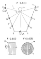
- Figure 1 shows a longitudinal section (right half) and a plan view (left half) of a pressure vessel according to the invention.
- the pressure vessel 1 is in this .4.us entrysbeispiel a multi-part welded version made of corrosion-resistant stainless steel, which is particularly suitable for storing and removing noble, special gases or gas mixtures of high purity and from a welded base part 2, a cylindrical jacket 3 and a head part 4 with molded tem neck 5 there.
- the cylindrical jacket 3 is a longitudinally welded tube with a weld seam 7 running parallel to the container axis 6, but a seamless tube can also be used for this.
- Bottom 2 and head part 4 are connected to the cylindrical jacket 3 by means of circular welds 8, 9, the three parts 2, 3, 4 of the pressure vessel 1 having been subjected to a heat treatment after being shaped, before being welded to one another.
- the entire inner surface 10, 11, 12 of the pressure vessel 1, including the neck 5, is electropolished after the welding in order to reduce the roughness to a great extent and to reduce the remaining stresses.
- the inner surfaces 10, 11, 12 can also be electropolished before welding, with post-treatment of the circular weld seams 8, 9 being necessary, depending on the requirements.
- FIG. 2 the connection according to the invention is shown on an enlarged scale in longitudinal section.
- An adapter piece 14 which is designed as an essentially cylindrical hollow body, is connected to the neck 5 of the pressure vessel 1 by means of a union nut 15.
- the left half of the adapter piece 14 graphically represents the variant that the adapter piece 14 forms an integral unit with the connecting body 26 of the valve 25.
- the adapter piece 14 has in the region of the container-side end an outwardly extending collar 16 which, like the cylindrical part 17, is encompassed by the union nut 15.
- Connected to the bore part 18 of the union nut 15 is a part 19 which is provided with an internal thread and which is screwed to a neck 5 which carries an external thread 20 (FIG. 1).
- a recess 22 is provided, into which a corrosion-resistant metallic seal 32 is arranged.
- the seal 32 is pressed onto the end face 21 by the rotation of the union nut 15.
- a central shoulder 23 is provided at the end on the container side, which is slightly smaller in diameter than the bore 13 of the neck 5. So that during the rotation of the union nut 15 no abrasion of the seal 32 producing rotation of the adapter piece 14 is possible , a cross-sectional shape 24 deviating from the circular shape is provided at the valve-side end.
- two opposing secants are produced mechanically in a simple manner in order to be able to hold an open-end wrench or a comparable tool.
- Other cross-sectional profiles that enable the adapter piece 14 to be held may just as well be.
- Another possibility is to make two axially extending, mutually opposite blind holes in this valve-side end in order to insert a hook wrench.
- a standard valve 25 is screwed into the adapter piece 14 with its connecting body 26 carrying a thread 33.
- the adapter piece 14 can be welded to the connector body 26 and then electropolished without the sensitive mechanical valve parts (not shown here).
- the known protective cap 27 is screwed onto an element 28 of the head part 4 which has an external thread. This element 28 can also be a ring shrunk onto the head part 4 (not shown here). This separation of the attachment of the protective cap 27 and the valve 25 ensures that undesirable effects on the protective cap 27 cannot be transmitted to the valve 25 and the seal 32.
- FIG. 3 shows an alternative embodiment of the connection.
- the adapter piece 30 is connected directly to the neck 5 of the pressure vessel 1 via a seam 31.
- the left half of the adapter piece 14 graphically represents the variant that the adapter piece 14 forms an integral unit with the connecting body 26 of the valve 25.
- the union nut 15 (FIG. 2) and the seal 32 (FIG. 2) can be omitted.
- the standard valve 25 is screwed into the adapter piece 3.
- Other possible types of fastening of the valve 25 with the adapter piece 30 are not shown here.
Abstract
Description
Die Erfindung betrifft einen Druckbehälter zur Speicherung und Entnahme von Edelgas-, Spezialgas oder Gasgemischen hoher Reinheit gemäß dem Gattungsbegriff des Hauptanspruches.The invention relates to a pressure vessel for storing and removing noble gas, special gas or gas mixtures of high purity according to the preamble of the main claim.
Für die Fertigung u. a. in der Elektronikindustrie werden Gase hoher Reinheit benötigt. Bei der Speicherung und dem Transport derartiger Gase in üblichen Stahlflaschen kommt es zu Verunreinigungen und zur Beeinträchtigung der Gemischkonstanz, die die Verwendungsmöglichkeit der Gase beeinträchtigen. Diese Bedingungen gelten insbesondere für korrosive, giftige und brennbare Gase, die z. B. bei der Halbleitertechnik benötigt werden.For manufacturing u. a. Gases of high purity are required in the electronics industry. When such gases are stored and transported in conventional steel bottles, there is contamination and the consistency of the mixture is impaired, which impair the possibility of using the gases. These conditions apply in particular to corrosive, toxic and flammable gases which, for. B. in semiconductor technology.
Bekannt ist es, daß die Oberflächenbeschaffenheit und die Sauberkeit der Innenoberfläche des Druckbehälters auf die Reinheit und die Gemischstabilität der Gase großen Einfluß hat. Darüber hinaus ist aber auch das verwendete Material von Einfluß. Andererseits wird aus wirtschaftlichen Gründen des Transportes und der Lagerung verlangt, daß die Gase unter hohem Druck gehalten werden können. Dies erfordert auch ein hochfestes Druckbehältermaterial. Die Festigkeitsanforderungen erfüllt die bekannte Stahlflasche aus unlegiertem oder niedrig legiertem Stahl zwar bestens; sie wird nach dem stand der Technik aber dennoch nicht im Hinblick auf die Reinheits- und Korrosionsanforderung für geeignet angesehen.It is known that the surface quality and the cleanliness of the inner surface of the pressure vessel have a great influence on the purity and the mixture stability of the gases. In addition, the material used is also influential. On the other hand, for economic reasons of transportation and storage, it is required that the gases can be kept under high pressure. This also requires a high-strength pressure vessel material. The known steel bottle made of unalloyed or low-alloy steel fulfills the strength requirements perfectly; However, according to the state of the art, it is not considered suitable in terms of the purity and corrosion requirements.
Man hat bereits erkannt, daß die Gasverunreinigung um so geringer ist, je kleiner die Oberflächenrauheit der Druckbehälterinnenwand ist. Zur Erzeugung einer möglichst glatten Innenoberfläche ist in der vorbekannten DE-AS 23 64 377 vorgeschlagen worden, eine Flasche aus ferritisch-perlitischem Stahl innen galvanisch zu verzinnen oder zu verzinken. An anderer Stelle wird vorgeschlagen, die Innenoberfläche mit Quarzkugeln zu strahlen und chemisch oder mit Ultraschall zu reinigen.It has already been recognized that the lower the surface roughness of the pressure vessel inner wall, the lower the gas contamination. In order to produce the smoothest possible inner surface, it has been proposed in the previously known DE-AS 23 64 377 to galvanically tin or galvanize a bottle made of ferritic-pearlitic steel. Elsewhere, it is proposed that the inner surface be blasted with quartz balls and cleaned chemically or with ultrasound.
Aufgabe der Erfindung ist es, einen Druckbehälter mit einem Anschluß mit verbesserten Eigenschaften für die Speicherung und Entnahme von Edelgasen, Spezialgasen und Gasgemischen hoher Reinheit zu schaffen, um eine Verunreinigung und/oder eine Beeinträchtigung der Gemischkonstanz der Gase beim Lagern zu vermeiden. Der Druckbehälter sowie der Anschluß sollen überdies für Gasdrücke bis ca. 200 bar geeignet und kostengünstig herzustellen sein.The object of the invention is to provide a pressure vessel with a connection with improved properties for the storage and removal of noble gases, special gases and gas mixtures of high purity in order to avoid contamination and / or impairment of the mixture constancy of the gases during storage. The pressure vessel and the connection should also be suitable for gas pressures up to approx. 200 bar and inexpensive to manufacture.
Die Lösung der Aufgabe ist ein Druckbehälter mit den kennzeichnenden Merkmalen des Hauptanspruches.The solution to the problem is a pressure vessel with the characterizing features of the main claim.
Das Material des Druckbehälters ist gegen alle in Betracht kommenden Gase und Gasgemische in hohem Maße chemisch beständig. Es hat überdies die Eigenschaft, daß es sich galvanisch hochglanzpolieren (elektrochemisches Polieren) läßt, wodurch die aktive Oberfläche eingeebnet und gegunüber dem unpolierten Zustand erheblich verkleinert wird. Dadurch wird der Absorptionseffekt der Gase auf die Behälterinnenwand sowie die Abgabe von Partikeln stark vermindert. Außerdem ist die Innenoberfläche nach dem Elektropolieren frei von mechanischen Restspannungen, die durch den Herstellungsprozeß entstanden sind, was die Sorptionsneigung des Behältermaterials vermindert.The material of the pressure vessel is chemically resistant to a great extent to all gases and gas mixtures under consideration. It also has the property that it can be galvanically mirror-polished (electrochemical polishing), as a result of which the active surface is leveled and considerably reduced compared to the unpolished state. This greatly reduces the absorption effect of the gases on the inner wall of the container and the release of particles. In addition, after electropolishing, the inner surface is free of residual mechanical stresses that have arisen from the manufacturing process, which reduces the tendency of the container material to sorb.
Für die vorgesehenen Zwecke werden die Druckbehälter, insbesondere Gasflaschen, die hauptsächlich die üblichen Einheitsabmessungen haben, im Tauchverfahren poliert. Für größere Abmessungen kann vorgesehen sein, daß der Druckbehälter selbst das Gefäß zur Aufnahme des beim Elektropolieren benötigten Elektrolyten ist. Auf jeden Fall wird eine kathodische Gleichstromelektrode von ausreichender Länge in den Druckbehälter eingeführt, damit auch der Boden und das Kopfteil, sowie im Falle des mehr teilig geschweißten Druckbehälters die Schweiß- oder Lötnähte innen poliert werden. Ein derartiger Druckbehälter, insbesondere mit einem Nickelgehalt an der oberen Grenze wird für höhere Drücke in dem angegebenen Bereich ziemlich schwer und damit teuer sein, da das Material in geglühtem Zustand nur mässige Festigkeitseigenschaften besitzt. Es werden deswegen außerdem die Maßnahmen nach den Unteransprüchen vorgeschlagen. Eine der Möglichkeiten ist, mit einem reduzierten Nickelgehalt ein ferritisch-austenitisches Mischgefüge zu erzeugen, das mit geringem Molybdänzusatz die Streckgrenze des Materials um etwa den Faktor 2,5 anhebt gegenüber dem üblichen austenitischen Material.For the intended purposes, the pressure vessels, in particular gas bottles, which mainly have the usual unit dimensions, are polished in the dipping process. For larger dimensions, it can be provided that the pressure vessel itself is the vessel for receiving the electrolyte required for electropolishing. In any case, a cathodic direct current electrode of sufficient length is inserted into the pressure vessel so that the bottom and the head part and, in the case of the pressure vessel welded in several parts, the weld or soldered seams are polished on the inside. Such a pressure vessel, in particular with a nickel content at the upper limit, will be rather heavy and therefore expensive for higher pressures in the range given, since the material in the annealed state has only moderate strength properties. Therefore, the measures according to the subclaims are also proposed. One of the possibilities is to create a ferritic-austenitic mixed structure with a reduced nickel content, which increases the yield strength of the material by about a factor of 2.5 compared to the usual austenitic material with a small amount of molybdenum.
Eine andere Maßnahme zur Gewichtsreduzierung ist im Falle des mehrteilig geschweißten Druckbehälters die zusätzliche Kaltverfestigung des zylindrischen Mantels des Druckbehälters. Dazu wird ein nahtloses oder geschweißtes Rohr bis in die Nähe des Anschlußbereiches um mindestens 10 bis 35 % in der Wanddicke abgestreckt, bevor es mit dem Kopf- und Bodenteil verschweißt wird. Im Anschlußbereich muß die ursprüngliche Wanddicke bestehen bleiben, da ein Anlassen des kaltverfestigten Bereiches durch das Verbindungsschweißen bzw. Löten die angestrebte Festigkeitserhöhung zunichte machen würde. Wegen der bei einigen Typen großen Länge des Druckbehälters im Verhältnis zu seinem Durchmesser wirkt sich das Abstrecken zum Beispiel auf 75 % der ursprünglichen Wanddicke erheblich gewichtsmindernd aus.Another measure for reducing weight in the case of the multi-part welded pressure vessel is the additional work hardening of the cylindrical jacket of the pressure vessel. For this purpose, a seamless or welded pipe is stretched close to the connection area by at least 10 to 35% in the wall thickness before it is welded to the head and bottom part. The original wall thickness must remain in the connection area, since tempering the work-hardened area through the connection welding or soldering would negate the desired increase in strength. Because of the large length of the pressure vessel in relation to its diameter in some types, the stretching, for example, has a considerable weight-reducing effect on 75% of the original wall thickness.
Eine weitere Maßnahme in Hinblick auf Gewichtseinsparung ist die Verstärkung des zylindrischen Teiles des Druckbehälters mit einer spannungslos oder unter Zug aufgebrachten von einem Kunststoff umhüllte Faserwicklung. Über diese Wicklung wird je nach Dicke und Vorspannung ein Teil der durch den Innendruck verursachten Spannung abgebaut, so daß die Wanddicke des metallischen Körpers im zylindrischen Bereich reduziert werden kann. Der Effekt der Gewichtseinsparung wird noch verstärkt, wenn der Vorschlag einer Faserwicklung mit einem kaltverfestigten zylindrischen Mantel kombiniert wird.A further measure with regard to saving weight is the reinforcement of the cylindrical part of the pressure vessel with a fiber winding covered by a plastic, which is applied without tension or under tension. Depending on the thickness and preload, part of the tension caused by the internal pressure is reduced via this winding, so that the wall thickness of the metallic body in the cylindrical region can be reduced. The effect of saving weight is further enhanced if the proposal of a fiber winding is combined with a cold-hardened cylindrical jacket.
Der Druckbehälter kann in einer nahtlos einteiligen oder in einer mehrteilig geschweißten Ausführung hergestellt werden.The pressure vessel can be in a seamless one-piece or in a multi-piece welded version tion.
Der Vorteil der mehrteilig geschweißten Ausführung liegt darin, daß die einzelnen Teile leicht bearbeitet werden können, so daß die Innenoberflächen vor dem Elektropolieren entsprechend geglättet werden können. Alternativ ist es auch möglich, die einzelnen Teile des Druckbehälters vor dem Zusammenfügen zu elektropolieren und, falls erforderlich, nur die Nahtbereiche einer Nachbehandlung zu unterziehen. Die beim Warmumformen des Kopf- bzw. Bodenteiles einer einteiligen Flasche entstehenden, meistens kaum zu vermeidenden, kleinen Oberflächenanrisse können durch das Elektropolieren nur mit großem Aufwand und nur teilweise beseitigt werden. Der Effekt des Elektropolierens ist um so größer und der dafür erforderliche Aufwand um so geringer, je glatter die Oberfläche auf mechanischem Wege vorbereitet ist. Eine solche glatte Oberfläche ist auch über den Weg eines durch Kaltumformung hergestellten einteiligen Druckbehälters erreichbar.The advantage of the multi-part welded design is that the individual parts can be easily machined so that the inner surfaces can be smoothed accordingly before electropolishing. Alternatively, it is also possible to electropolish the individual parts of the pressure vessel before assembly and, if necessary, only to subject the seam areas to post-treatment. The small surface cracks that occur during hot forming of the top or bottom part of a one-piece bottle, which are usually unavoidable, can only be eliminated with great effort and only partially by electropolishing. The effect of electropolishing is greater and the effort required for this is reduced, the smoother the surface is mechanically prepared. Such a smooth surface can also be achieved by way of a one-piece pressure vessel produced by cold forming.
Der Aufwand zur Verminderung der Rauheit, der in bezug auf die Innenoberflächen des Druckbehälters getrieben wird, muß auch den Anschluß mit einschließen, da ansonsten das Ziel einer deutlichen Partikelreduzierung für das Gesamtsystem nicht gewährleistet werden kann. Dazu ist es erforderlich, daß zum einen der Halsbereich des Druckbehälters elektropolierbar sein muß und die Verbindung des Ventils mit dem Druckbehälter zu keinem Materialabrieb führen darf. Zur Lösung dieses Problems wird für große Druckbehälter vorgeschlagen, die Bohrung im Halsbereich so groß wie möglich, d. h. gleich größer 40 mm Durchmesser zu wählen und statt des üblichen genormten kegeligen Innengewindes im Hals ein drehsicherbares Adapterstück anzuordnen, daß mit Hilfe einer Überwurfmutter mit dem Hals verbunden ist. Zwischen Adapterstück und Stirnfläche des Halses wird eine korrosionsbeständige metallische Dichtung eingesetzt. Diese Anordnung hat den Vorteil, daß durch das drehgesicherte Adapterstück die Dichtung nur auf Druck beansprucht und damit kein Abrieb erzeugt wird. Für die Drehsicherung des Adapterstückes gibt es mehrere Möglichkeiten, z. B. ein geradzahliges Mehrkantenprofil in Form von Sekanten zur Aufnahme eines Maulschlüssels oder eines entsprechenden Werkzeuges am ventilseitigen Ende des Adapterstückes anzuordnen oder zwei in axialer Richtung sich erstreckende Sacklochbohrungen vorzusehen, um einen Hakenschlüssel oder ein entsprechendes Werkzeug anzusetzen.The effort to reduce the roughness, which is driven in relation to the inner surfaces of the pressure vessel, must also include the connection, since otherwise the goal of a significant particle reduction for the overall system cannot be guaranteed. For this it is necessary that the neck area of the pressure vessel must be electropolished and the connection of the valve to the pressure vessel must not lead to material abrasion. To solve this problem, it is proposed for large pressure vessels that the bore in the neck area be as large as possible, i. H. to choose the same size larger than 40 mm and instead of the usual standardized conical internal thread in the neck to arrange a lockable adapter piece that is connected to the neck with the help of a union nut. A corrosion-resistant metallic seal is inserted between the adapter piece and the end face of the neck. This arrangement has the advantage that the seal is only stressed by the non-rotatable adapter piece and therefore no abrasion is generated. There are several options for securing the adapter against rotation, e.g. B. to arrange an even polygonal profile in the form of secants for receiving an open-end wrench or a corresponding tool at the valve-side end of the adapter piece or to provide two blind holes extending in the axial direction in order to attach a hook wrench or a corresponding tool.
Die Verbindung des Adapterstückes mit dem Ventil kann in der Weise erfolgen, daß das Adapterstück mit dem Anschlußkörper des Ventils verschweißt oder gelötet wird und anschließend die gesamte Vorrichtung im Tauchverfahren elektropoliert wird. Eine Abwandlung dieser Verbindung besteht darin, den Anschlußkörper des Ventils in der Bohrung des Adapterstückes anzuordnen und an der Übergangsstelle außen und/oder innen eine Naht vorzusehen. Eine weitere Möglichkeit sieht vor, daß das Adapterstück im Bohrungsbereich mit einem genormten Innengewinde versehen wird und nach dem Aufschrauben des Anschlußkörpers des Ventils die gesamte Vorrichtung ebenfalls elektropoliert wird. Zur weiteren Absicherung kann auch eine dichtende Naht an der Übergangsstelle außen und/oder innen angebracht werden. Die Schraubverbindung ohne eine dichtende Naht hätte den Vorteil, daß das Ventil zu jeder Zeit auswechselbar ist bei Wiederverwendbarkeit des Adapterstückes. Bildet man das Adapterstück als integrale Einheit des Anschlußkörpers des Ventils aus, dann kann diese Einheit nach dem Elektropolieren direkt und ohne eine weitere Verbindungsnaht mit dem Hals des Druckbehälters verschraubt werden. Ebenso ist es möglich, das Adapterstück und den Hals als integrale Einheit auszubilden und den Ventilkörper mit einem entsprechenden Kragen am Hals festzuschrauben. Alternativ zu dem beschriebenen Ausführungsbeispiel gibt es auch die Möglichkeit, das Adapterstück direkt über eine Naht mit dem Hals des Druckbehälters zu verbinden. Bei dieser Art der Ausführung würde der Dichtring und die Überwurfmutter entfallen. Die Verbindungsmöglichkeiten des Adapterstückes mit dem Ventil entsprechen denen, wie sie bereits vorher für das andere Ausführungsbeispiel erläutert worden sind.The adapter piece can be connected to the valve in such a way that the adapter piece is welded or soldered to the connecting body of the valve and then the entire device is electropolished in the immersion process. A modification of this connection is to arrange the connecting body of the valve in the bore of the adapter piece and to provide a seam on the outside and / or inside at the transition point. A further possibility provides that the adapter piece is provided with a standardized internal thread in the bore area and that the entire device is also electropolished after the connection body of the valve has been screwed on. For further protection, a sealing seam can also be attached to the transition point outside and / or inside. The screw connection without a sealing seam would have the advantage that the valve can be replaced at any time if the adapter piece is reusable. If the adapter piece is formed as an integral unit of the connecting body of the valve, then this unit can be screwed to the neck of the pressure vessel directly after the electropolishing and without a further connecting seam. It is also possible to design the adapter piece and the neck as an integral unit and to screw the valve body to the neck with a corresponding collar. As an alternative to the exemplary embodiment described, there is also the possibility of connecting the adapter piece directly to the neck of the pressure vessel via a seam. With this type of design, the sealing ring and the union nut would be omitted. The connection options of the adapter piece with the valve correspond to those as have already been explained for the other embodiment.
Die Schutzkappe wird an einem ein Außengewinde tragenden Abschnitt des Kopfteiles aufgeschraubt, wobei dieser Abschnitt integraler Teil des Kopfteiles sein kann oder als aufgeschrumpfter Ring ausgebildet ist. Durch diese Trennung der Befestigung der Schutzkappe und des Ventils wird sichergestellt, daß bei einem versehentlichen Umfallen der Flasche oder bei einer nicht beabsichtigten Schlagbeanspruchung von außen auf die Schutzkappe der Ventilanschluß nicht in Mitleidenschaft gezogen wird.The protective cap is screwed onto a section of the head part that carries an external thread, this section can be an integral part of the head part or is designed as a shrunk-on ring. This separation of the fastening of the protective cap and the valve ensures that the valve connection is not affected in the event of the bottle accidentally falling over or in the event of an unintended external impact on the protective cap.
Das Material, das für die Herstellung des Adapterstückes, der Überwurfmutter und des Ventilkörpers verwendet wird, muß nicht identisch mit dem des Druckbehälters sein, mit der Ausnahme, daß daß Adapterstück integraler Bestandteil des Halses ist. Es kann im Hinblick auf eine gute Zerspanbarkeit und Formgebungsmöglichkeit entsprechend gewählt werden, muß aber die Forderungen der Korrosionsbeständigkeit und Festigkeit ebenfalls erfüllen.The material used to make the adapter, union nut and valve body need not be identical to that of the pressure vessel, except that the adapter is an integral part of the neck. With regard to good machinability and shaping possibilities, it can be chosen accordingly, but must also meet the requirements of corrosion resistance and strength.
Die Erfindung wird an einem schematisch dargestellten Ausführungsbeispiel näher erläutert.The invention is explained in more detail using a schematically illustrated embodiment.
Es zeigt
Figur 1 einen Längsschnitt und eine Draufsicht durch einen mehrteilig geschweißten Druckbehälter ohne Ventil und Schutzkappe- Figur 2 einen Längsschnitt des erfindungsgemäßen Anschlusses
Figur 3 wie Fig. 2, jedoch mit einem angeschweißten Adapterstück
- 1 shows a longitudinal section and a top view through a multi-part welded pressure vessel without valve and protective cap
- Figure 2 shows a longitudinal section of the connection according to the invention
- Figure 3 as Fig. 2, but with a welded adapter
Figur 1 zeigt einen Längsschnitt (rechte Hälfte) und eine Draufsicht (linke Hälfte) eines erfindungsgemäßen Druckbehälters. Der Druckbehälter 1 ist in diesem .4.usführungsbeispiel eine mehrteilige geschweißte Ausführung aus korrosionsbeständigem Edelstahl, der besonders geeignet ist zur Speicherung und Entnahme von Edel-, Spezialgasen oder Gasemischen hoher Reinheit und aus einem miteinander verschweißten Bodenteil 2, einem zylindrischen Mantel 3 und einem Kopfteil 4 mit angeformtem Hals 5 besteht. Der zylindrische Mantel 3 ist in diesem Ausführungsbeispiel ein längsnahtgeschweißtes Rohr mit einer parallel zur Behälterachse 6 verlaufenden Schweißnaht 7, es kann aber ebenso dafür ein nahtloses Rohr verwendet werden. Boden 2- und Kopfteil 4 sind über Rundschweißnähte 8, 9 mit dem zylindrischen Mantel 3 verbunden, wobei die drei Teile 2,3,4 des Druckbehälters 1 nach ihrer Formgebung einer Wärmebehandlungunterzogen worden sind, bevor sie miteinander verschweißt wurden. Die gesamte Innenoberfläche 10,11,12 des Druckbehälters 1 einschließlich des Halses 5 wird nach dem Verschweißen elektropoliert, um die Rauheit in starkem Maße zu vermindern und die noch verbliebenen Restspannungen abzubauen. Zur Durchführung des Verfahrens und im Hinblick auf die Revision bzw. für eine spätere Nachrevision ist es erforderlich, den Durchgang (hier dargestellt durch den Pfeil 13) im Hals 5 möglichst groß zu wählen und ihn konstruktiv glatt ohen störende Kanten und Vorsprünge zu gestalten. Das Elektropolieren der Innenoberflächen 10,11,12 kann auch vor dem Verschweißen erfolgen, wobei je nach Anforderung eine Nachbehandlung der Rundschweißnähte 8,9 erforderlich sein kann.Figure 1 shows a longitudinal section (right half) and a plan view (left half) of a pressure vessel according to the invention. The
In Figur 2 wird in einem vergrößerten Maßstab im Längsschnitt der erfindungsgemäße Anschluß dargestellt. Ein Adapterstück 14, das als ein im wesentlichen zylinderförmiger Hohlkörper ausgebildet ist, ist mit Hilfe einer Überwurfmutter 15 mit dem Hals 5 des Druckbehälters 1 verbunden. Dabei stellt die linke Hälfte des Adapterstückes 14 zeichnerisch die Variante dar, daß das Adapterstück 14 mit dem Anschlußkörper 26 des Ventils 25 eine integrale Einheit bildet. Das Adapterstück 14 weist im Bereich des behälterseitigen Endes einen nach außen sich erstreckenden Kragen 16 auf, der ebenso wie der zylindrische Teil 17 von der Überwurfmutter 15 umfaßt wird. An dem Bohrungsteil 18 der Überwurfmutter 15 schließt sich ein mit einem Innengewinde versehener Teil 19 an, der mit einem ein Außengewinde 20 (Figur 1) tragenden Hals 5 verschraubt ist. In einer des Stirnfläche 21 des Halses 5 zugewandten Kragenseite des Adapterstückes 14 ist eine Ausnehmung 22 vorgesehen, in die eine korrosionsbeständige metallische Dichtung 32 angeordnet wird. Durch die Drehung der Überwurfmutter 15 wird die Dichtung 32 auf die Stirnfläche 21 gepreßt. Zur sicheren Führung des Adapterstückes 14 ist am behälterseitigen Ende ein zentrischer Absatz 23 vorgesehen, der im Durchmesser etwas kleiner ist als die Bohrung 13 des Halses 5. Damit während der Drehung der Überwurfmutter 15 keine einen Abrieb der Dichtung 32 erzeugende Drehung des Adapterstückes 14 möglich ist, ist am ventilseitigen Ende eine von der Kreisform abweichende Querschnittsform 24 vorgesehen. In diesem Ausführungsbeispiel werden in einfacher Weise zwei sich gegenüberliegende Sekanten mechanisch hergestellt, um einen Maulschlüssel oder ein vergleichbares Werkzeug aufnehmen zu können. Ebenso gut können es andere Querschnittsprofile sein, die ein Halten des Adapterstückes 14 ermöglichen. Eine andere Möglichkeit besteht darin, an diesem ventilseitigen Ende zwei in axialer Richtung sich erstreckende, einander gegenüberliegende Sacklochbohrungen anzubringen, um einen Hakenschlüssel hineinzustecken.In Figure 2, the connection according to the invention is shown on an enlarged scale in longitudinal section. An
Bei diesem Ausführungsbeispiel wird ein Standard-Ventil 25 mit seinem ein Gewinde 33 tragenden Anschlußkörper 26 in das Adapterstück 14 hineingeschraubt. Alternativ kann das Adapterstück 14 mit dem Anschlußkörper 26 verschweißt werden und danach ohne die empfindlichen mechanischen Ventilteile (hier nicht dargestellt), elektropoliert werden. Die bekannte Schutzkappe 27 wird auf einem ein Außengewinde aufweisendes Element 28 des Kopfteiles 4 aufgeschraubt. Dieses Element 28 kann auch ein auf das Kopfteil 4 aufgeschrumpfter Ring sein (hier nicht dargestellt). Durch diese Trennung der Befestigung der Schutzkappe 27 und des Ventils 25 wird sichergestellt, daß unerwünschte Einwirkungen auf die Schutzkappe 27 nicht auf das Ventil 25 und auf die Dichtung 32 übertragen werden können.In this exemplary embodiment, a standard valve 25 is screwed into the
Figur 3 zeigt eine alternative Ausführung des Anschlusses. In diesem Fall wird das Adapterstück 30 direkt über eine Naht 31 mit dem Hals 5 des Druckbehälters 1 verbunden. Vergleichbar wie in Figur 2 stellt die linke Hälfte des Adapterstückes 14 zeichnerisch die Variante dar, daß das Adapterstück 14 mit dem Anschlußkörper 26 des Ventils 25 eine integrale Einheit bildet. Dadurch können die Überwurfmutter 15 (Fig. 2) und die Dichtung 32 (Fig. 2) entfallen. Das Standard-Ventil 25 ist ebenso wie in Fig. 2 in das Adapterstück 3 hineingeschraubt. Andere mögliche Befestigungsarten des Ventils 25 mit dem Adapterstück 30 sind hier nicht dargestellt.Figure 3 shows an alternative embodiment of the connection. In this case, the adapter piece 30 is connected directly to the
Claims (29)
daß
that
daß der Druckbehälter (1) mehrteilig ist und der Boden (2), der Mantel (3) und das Kopfteil (4) durch eine Schweiß- oder Lötnaht miteinander verbunden sind.2. Pressure vessel according to claim 1, characterized in
that the pressure vessel (1) is in several parts and the bottom (2), the jacket (3) and the head part (4) are connected to one another by a welded or soldered seam.
daß der Mantel (3) ein nahtloses oder geschweißtes Rohr ist.3. Pressure vessel according to claim 2, characterized in
that the jacket (3) is a seamless or welded tube.
dadurch gekennzeichnet,
daß der Edelstahl 3 - 6 % Mangan, 15-18% Nickel, 2,7-3,7% Molybdän, 0,20-0,35% Stickstoff und max. 0,25% Niob enthält.4. Pressure vessel according to claim 1,
characterized,
that the stainless steel 3 - 6% manganese, 15-18% nickel, 2.7-3.7% molybdenum, 0.20-0.35% nitrogen and max. Contains 0.25% niobium.
dadurch gekennzeichnet,
daß der Edelstahl 4 bis 9% Nickel und 0,5 bis 3% Molybdän enthält.5. Pressure vessel according to claim 1,
characterized,
that the stainless steel contains 4 to 9% nickel and 0.5 to 3% molybdenum.
dadurch gekennzeichnet,
daß für den Mantel (3) ein Rohr verwendet wird, das bis in die Nähe des Anschlußbereiches durch Kaltverformung um mindestens 10 bis 35% in der Wanddicke abgestreckt ist, bevor es mit dem Kopf (4) und dem Bodenteil (2) verbunden wird.6. Pressure vessel according to claims 2 and 3,
characterized,
that a tube is used for the jacket (3), which is drawn into the vicinity of the connection area by cold working by at least 10 to 35% in the wall thickness before it is connected to the head (4) and the base part (2).
daß der zylindrische Teil des Druckbehälters (1) eine außen aufgebrachte einlagige oder mehrlagige Faserwicklung aufweist.7. Pressure vessel according to claims 1-6, characterized in
that the cylindrical part of the pressure vessel (1) has an externally applied single-layer or multi-layer fiber winding.
dadurch gekennzeichnet,
daß die spannungslos oder unter Zug aufgewikkelten Fasern mit Kunststoff umhüllt sind.8. Pressure vessel according to claim 7,
characterized,
that the tension-free or wound-up fibers are covered with plastic.
dadurch gekennzeichnet,
daß das Adapterstück (14, 30) als ein im wesentlichen zylinderförmiger Hohlkörper ausgebildet ist, mit einer für die Verbindung mit dem Hals (5) und dem Ventil (25) passenden Querschnittsform.9. Pressure vessel according to claim 1,
characterized,
that the adapter piece (14, 30) is designed as an essentially cylindrical hollow body, with a cross-sectional shape suitable for connection to the neck (5) and the valve (25).
daß die Bohrung des Adapterstückes (30) mit der des Halses (5) und mit der des Ventilkörpers (26) fluchtet und die Verbindungsstellen eine Schweiß-(31) oder Lötnaht aufweisen.10. Pressure vessel according to claim 9, characterized in
that the bore of the adapter piece (30) is aligned with that of the neck (5) and with that of the valve body (26) and the connection points have a welded (31) or soldered seam.
daß der Ventilkörper (26) in der Bohrung des Adapterstückes (30) angeordnet ist und die Übergangsstelle Adapterstück (14,30)/Ventilkörper (26) außen und/oder innen eine Naht aufweist.11. Pressure vessel according to claim 10, characterized in
that the valve body (26) is arranged in the bore of the adapter piece (30) and the transition point adapter piece (14,30) / valve body (26) has a seam on the outside and / or inside.
dadurch gekennzeichnet,
daß das Adapterstück (30) mit dem Ventilkörper (26) eine nahtlose Einheit bildet und dem Hals (5) durch eine Naht (31) verbunden ist.12. Pressure vessel according to claim 9,
characterized,
that the adapter piece (30) forms a seamless unit with the valve body (26) and the neck (5) is connected by a seam (31).
dadurch gekennzeichnet,
daß das Adapterstück (30) mit dem Hals (5) eine nahtlose Einheit bildet und mit dem Ventilkörper (26) durch eine Naht (31) verbunden ist.13. Pressure vessel according to claim 9,
characterized,
that the adapter piece (30) forms a seamless unit with the neck (5) and is connected to the valve body (26) by a seam (31).
dadurch gekennzeichnet,
daß der Hals (5) mit einem in der Bohrung angeordnetem Gewinde zur Aufnahme eines Ventils (25) versehen ist.14. Pressure vessel according to claim 13,
characterized,
that the neck (5) is provided with a thread arranged in the bore for receiving a valve (25).
dadurch gekennzeichnet,
daß das Adapterstück (30) mit einem in der Bohrung angeordneten Gewinde (29) zur Aufnahme eines Ventils (25) versehen und mit dem Hals (5) durch eine Naht (31) verbunden ist.15. Pressure vessel according to claim 9,
characterized,
that the adapter piece (30) is provided with a thread (29) arranged in the bore for receiving a valve (25) and is connected to the neck (5) by a seam (31).
dadurch gekennzeichnet,
daß nach dem Einschrauben des Ventilkörpers (26) die übergangsstelle Adapterstück(30)/Ventilkörper (26) außen und/oder innen eine Dichtnaht aufweist.
Druckbehälter nach den Ansprüchen 1. und 9, dadurch gekennzeichnet,
daß das Adapterstück (14) drehsicherbar ausgebildet und mit dem Hals (5) durch eine ihn und den mit einem Außengewinde (20) versehenen Hals (5) umfassenden Überwurfmutter (15), die einen Bohrungs(18)- und einen innengewindeabschnitt (19) aufweist, verbunden und zwischen Hals (5) und Adapterstück (14) eine Dichtung (32) angeordnet ist,16. Pressure vessel according to claim 15,
characterized,
that after screwing in the valve body (26) the transition point adapter piece (30) / valve body (26) has a sealing seam on the outside and / or inside.
Pressure vessel according to claims 1 and 9, characterized in that
that the adapter piece (14) is designed to be secured against rotation and with the neck (5) by a union nut (15) which surrounds it and the neck (5) provided with an external thread (20) and which has a bore (18) and an internally threaded section (19) has, connected and a seal (32) is arranged between the neck (5) and adapter piece (14),
dadurch gekennzeichnet,
daß das Adapterstück (14) im Bereich des behälterseitigen Endes einen nach außen sich erstreckenden zylindrischen Kragen (16) und im Bereich des ventilseitigen Endes eine von der Kreisform abweichende Querschnittsform (24) aufweist.18. Pressure vessel according to claim 17,
characterized,
that the adapter piece (14) has an outwardly extending cylindrical collar (16) in the area of the container-side end and a cross-sectional shape (24) deviating from the circular shape in the area of the valve-side end.
dadurch gekennzeichnet,
daß das ventilseitige Ende des Adapterstückes (14) ein geradzahliges Mehrkantprofil (24) in Form von Sekanten zur Aufnahme eines Maulschlüssels oder eines vergleichbaren Werkzeugesaufweist.19. Pressure vessel according to claim 18,
characterized,
that the valve-side end of the adapter piece (14) has an even polygonal profile (24) in the form of secants for receiving an open-end wrench or a comparable tool.
dadurch gekennzeichnet,
daß das ventilseitige Ende des Adapterstückes (14) zwei in axialer Richtung sich erstreckende einander gegenüberstehende Sacklochbohrungen zur Aufnahme eines Hakenschlüssels aufweist.20. Pressure vessel according to claim 17,
characterized,
that the valve-side end of the adapter piece (14) has two mutually opposite blind holes extending in the axial direction for receiving a hook wrench.
dadurch gekennzeichnet,
daß das Adapterstück (14) am behälterseitigen Ende mit einem der Bohrung (13) des Halses (5) angepassten Zentrierabsatz (23) versehen und im Kragen (16) des Adapterstückes (14) auf der der Stirnfläche (21) des Halses (5)zugewandten Seite eine ringförmige Ausnehmung (22) zur Aufnahme der Dichtung (32) angeordnet ist.21. Pressure vessel after. claims 17 and 18,
characterized,
that the adapter piece (14) is provided at the container end with a centering shoulder (23) adapted to the bore (13) of the neck (5) and in the collar (16) of the adapter piece (14) on the end face (21) of the neck (5) an annular recess (22) for receiving the seal (32) is arranged on the facing side.
dadurch gekennzeichnet,
daß der Hals (5) in der Bohrung (13) einem dem Außendurchmesser des Adapterstückes (14) angepaßten Zentrierabsatz aufweist und in diesem Zentrierabsatz eine ringförmige Ausnehmung zur Aufnahme der Dichtung (32)angeordnet ist.22. Pressure vessel according to claims 17 and 18,
characterized,
that the neck (5) in the bore (13) has a centering shoulder adapted to the outer diameter of the adapter piece (14) and an annular recess for receiving the seal (32) is arranged in this centering shoulder.
daß die Bohrung (13) des Adapterstückes (14) mit der des Ventilkörpers (26) fluchtet und die Verbindungsstelle eine Schweiß- oder Lötnaht aufweist.23. Pressure vessel according to claim 17, characterized in that
that the bore (13) of the adapter piece (14) is aligned with that of the valve body (26) and the connection point has a welded or soldered seam.
daß der Ventilkörper (26) in der Bohrung (13) des Adapterstückes (14) angeordnet ist und die Übergangsstelle Adapterstück(14)/Ventilkörper (26) außen und/oder innen eine Naht aufweist.24. Pressure vessel according to claim 17, characterized in
that the valve body (26) is arranged in the bore (13) of the adapter piece (14) and the transition point adapter piece (14) / valve body (26) has a seam on the outside and / or inside.
daß das Adapterstück (14) mit dem Ventilkörper (26) eine nahtlose Einheit bildet.25. Pressure vessel according to claim 17, characterized in
that the adapter piece (14) with the valve body (26) forms a seamless unit.
dadurch gekennzeichnet,
daß das Adapterstück (14) mit dem Hals (5) eine nahtlose Einheit bildet26. Pressure vessel according to claim 17,
characterized,
that the adapter piece (14) with the neck (5) forms a seamless unit
dadurch gekennzeichnet,
daß zur Aufnahme eines Ventils (25) das Adapterstück (14) im Bohrungsbereich ein Innengewinde aufweist.27. Pressure vessel according to claim 17,
characterized,
that for receiving a valve (25) the adapter piece (14) has an internal thread in the bore area.
dadurch gekennzeichnet,
daß nach dem Einschrauben des Ventils (25) die Übergangsstelle Adapterstück(14)/Ventilkörper (26) außen und/oder innen eine Dichtnaht aufweist.28. Pressure vessel according to claim 27,
characterized,
that after screwing in the valve (25) the transition point adapter piece (14) / valve body (26) has a sealing seam on the outside and / or inside.
dadurch gekennzeichnet,
daß der Bohrungsabschnitt (18) der Überwurfmutter (15) der Außenkontur des Adapterstükkes (14) einschließlich des Kragens (16) und der daran anschließende Innengewindeabschnitt (19) dem Gewindeteil des Halses (5) angepaßt ist.29. Pressure vessel according to claim 17,
characterized,
that the bore section (18) of the union nut (15) of the outer contour of the adapter piece (14) including the collar (16) and the adjoining internal thread section (19) is adapted to the threaded part of the neck (5).
daß die Dichtung (32) ein aus korrosionsbeständigem Material hergestellter metallischer Dichtring ist.30. Pressure vessel according to claim 17, characterized in
that the seal (32) is a metallic sealing ring made of corrosion-resistant material.
Applications Claiming Priority (2)
| Application Number | Priority Date | Filing Date | Title |
|---|---|---|---|
| JP62270926A JPH01113744A (en) | 1987-10-27 | 1987-10-27 | Method and device for producing stereoscopic photographic image |
| JP270926/87 | 1987-10-27 |
Publications (3)
| Publication Number | Publication Date |
|---|---|
| EP0314608A2 true EP0314608A2 (en) | 1989-05-03 |
| EP0314608A3 EP0314608A3 (en) | 1990-05-30 |
| EP0314608B1 EP0314608B1 (en) | 1994-09-14 |
Family
ID=17492917
Family Applications (1)
| Application Number | Title | Priority Date | Filing Date |
|---|---|---|---|
| EP88730232A Expired - Lifetime EP0314608B1 (en) | 1987-10-27 | 1988-10-25 | Method of and apparatus for producing three-dimensional sculpture works on a desired reduced scale |
Country Status (8)
| Country | Link |
|---|---|
| US (1) | US4931817A (en) |
| EP (1) | EP0314608B1 (en) |
| JP (1) | JPH01113744A (en) |
| KR (1) | KR930011092B1 (en) |
| AU (1) | AU595732B2 (en) |
| CA (1) | CA1320367C (en) |
| DE (1) | DE3851503T2 (en) |
| HK (1) | HK155495A (en) |
Cited By (2)
| Publication number | Priority date | Publication date | Assignee | Title |
|---|---|---|---|---|
| EP0773475A1 (en) * | 1995-11-10 | 1997-05-14 | Rittaishashinzo Co., Ltd. | Method of producing photographic relief |
| ES2337969A1 (en) * | 2007-07-20 | 2010-04-30 | Universidad De Granada | Specular modeled horse. (Machine-translation by Google Translate, not legally binding) |
Families Citing this family (7)
| Publication number | Priority date | Publication date | Assignee | Title |
|---|---|---|---|---|
| JP2511196B2 (en) * | 1990-07-12 | 1996-06-26 | モンテス,フアン ドミンゲス | Process for 3D photography, copying and playback of still and moving images |
| US5703961A (en) * | 1994-12-29 | 1997-12-30 | Worldscape L.L.C. | Image transformation and synthesis methods |
| US6327381B1 (en) | 1994-12-29 | 2001-12-04 | Worldscape, Llc | Image transformation and synthesis methods |
| US7555157B2 (en) * | 2001-09-07 | 2009-06-30 | Geoff Davidson | System and method for transforming graphical images |
| US7239345B1 (en) | 2001-10-12 | 2007-07-03 | Worldscape, Inc. | Camera arrangements with backlighting detection and methods of using same |
| US20050273830A1 (en) * | 2002-10-30 | 2005-12-08 | Nds Limited | Interactive broadcast system |
| US7830900B2 (en) | 2004-08-30 | 2010-11-09 | Qualcomm Incorporated | Method and apparatus for an adaptive de-jitter buffer |
Citations (5)
| Publication number | Priority date | Publication date | Assignee | Title |
|---|---|---|---|---|
| US891013A (en) * | 1907-01-25 | 1908-06-16 | John Hammond Smith | Method of reproducing objects. |
| CH182977A (en) * | 1935-05-25 | 1936-03-15 | Filiberto Sallier De La Tour P | Process for the sculptural reproduction of a three-dimensional object by instant photography. |
| US3580758A (en) * | 1967-05-09 | 1971-05-25 | Isao Morioka | Method for reproducing three-dimensional image |
| FR2418099A1 (en) * | 1978-02-28 | 1979-09-21 | Morioka Isao | STEREOPHOTOGRAPHIC SCULPTURE PROCESS |
| DE3048457A1 (en) * | 1980-12-22 | 1982-07-22 | Agfa-Gevaert Ag, 5090 Leverkusen | Stereoscopic assembly of dimensional part images - involves multi-lens objective and common gathering lens |
Family Cites Families (3)
| Publication number | Priority date | Publication date | Assignee | Title |
|---|---|---|---|---|
| US3085923A (en) * | 1960-06-03 | 1963-04-16 | Kenneth L Agnew | Recording and reproducing the shape of three-dimensional objects |
| US3185602A (en) * | 1962-02-06 | 1965-05-25 | Morioka Isao | Method of manufacturing reliefs by photographic means |
| US3544402A (en) * | 1967-06-02 | 1970-12-01 | Battelle Development Corp | Photographic reproduction by discrete intersecting rays with compression in the third dimension |
-
1987
- 1987-10-27 JP JP62270926A patent/JPH01113744A/en active Granted
-
1988
- 1988-10-20 CA CA000580699A patent/CA1320367C/en not_active Expired - Lifetime
- 1988-10-20 US US07/260,925 patent/US4931817A/en not_active Expired - Lifetime
- 1988-10-21 AU AU24119/88A patent/AU595732B2/en not_active Ceased
- 1988-10-25 DE DE3851503T patent/DE3851503T2/en not_active Expired - Fee Related
- 1988-10-25 EP EP88730232A patent/EP0314608B1/en not_active Expired - Lifetime
- 1988-10-26 KR KR1019880013964A patent/KR930011092B1/en not_active IP Right Cessation
-
1995
- 1995-09-28 HK HK155495A patent/HK155495A/en not_active IP Right Cessation
Patent Citations (5)
| Publication number | Priority date | Publication date | Assignee | Title |
|---|---|---|---|---|
| US891013A (en) * | 1907-01-25 | 1908-06-16 | John Hammond Smith | Method of reproducing objects. |
| CH182977A (en) * | 1935-05-25 | 1936-03-15 | Filiberto Sallier De La Tour P | Process for the sculptural reproduction of a three-dimensional object by instant photography. |
| US3580758A (en) * | 1967-05-09 | 1971-05-25 | Isao Morioka | Method for reproducing three-dimensional image |
| FR2418099A1 (en) * | 1978-02-28 | 1979-09-21 | Morioka Isao | STEREOPHOTOGRAPHIC SCULPTURE PROCESS |
| DE3048457A1 (en) * | 1980-12-22 | 1982-07-22 | Agfa-Gevaert Ag, 5090 Leverkusen | Stereoscopic assembly of dimensional part images - involves multi-lens objective and common gathering lens |
Cited By (3)
| Publication number | Priority date | Publication date | Assignee | Title |
|---|---|---|---|---|
| US5768643A (en) * | 1995-10-11 | 1998-06-16 | Rittaishashinzo Co., Ltd. | Method of producing photographic relief |
| EP0773475A1 (en) * | 1995-11-10 | 1997-05-14 | Rittaishashinzo Co., Ltd. | Method of producing photographic relief |
| ES2337969A1 (en) * | 2007-07-20 | 2010-04-30 | Universidad De Granada | Specular modeled horse. (Machine-translation by Google Translate, not legally binding) |
Also Published As
| Publication number | Publication date |
|---|---|
| EP0314608B1 (en) | 1994-09-14 |
| EP0314608A3 (en) | 1990-05-30 |
| JPH01113744A (en) | 1989-05-02 |
| AU2411988A (en) | 1989-04-27 |
| DE3851503D1 (en) | 1994-10-20 |
| US4931817A (en) | 1990-06-05 |
| KR930011092B1 (en) | 1993-11-20 |
| HK155495A (en) | 1995-10-06 |
| AU595732B2 (en) | 1990-04-05 |
| KR890007115A (en) | 1989-06-19 |
| DE3851503T2 (en) | 1995-01-19 |
| CA1320367C (en) | 1993-07-20 |
| JPH0447295B2 (en) | 1992-08-03 |
Similar Documents
| Publication | Publication Date | Title |
|---|---|---|
| DE3736579C2 (en) | ||
| DE3001666C2 (en) | Corrugated stainless steel conduit and method of making the same | |
| EP0314608A2 (en) | Method of and apparatus for producing three-dimensional sculpture works on a desired reduced scale | |
| DE102012109015B3 (en) | tank containers | |
| DD273613A1 (en) | head drum | |
| EP0110090B1 (en) | Nuclear reactor fuel assembly | |
| EP0303840A2 (en) | Valve bushing for the receipt of the gas bottle valve of a pressurised-gas container made from highly alloyed chromium-nickel steels | |
| DE3218057C2 (en) | ||
| DE19611711A1 (en) | Arc welding process and associated studs with a tapered annular weld rim | |
| DE2713309B2 (en) | Method for eliminating residual magnetism after direct current arc welding | |
| EP0587926A1 (en) | Fuel rod for nuclear reactor and welding device for its manufacture | |
| DE1775788A1 (en) | Housing especially made of steel tube for hydraulic or hydropneumatic shock absorbers | |
| DE2819714A1 (en) | Immersion lance for treating molten metals, esp. steel - where lance is made using two tubes of different shape, preventing vibration and increasing lance life | |
| DE3003025A1 (en) | Joining steel concrete reinforcing bars - involves screwing threaded socket onto threaded bolts welded onto bar ends | |
| EP0000379B1 (en) | Method for arc stud welding with ignition by elevation, and welding gun to apply this method. | |
| DE3721818A1 (en) | CONTAINER FOR HIGH-PURITY LIQUIDS | |
| DE2123101A1 (en) | Compensation piece | |
| DE3815347A1 (en) | MULTI-PIECE PRESSURE TANK | |
| DE2229022C3 (en) | Device for the separate introduction of at least two special fluids into nozzles to be fed separately | |
| DE2416545B1 (en) | Nozzle holder for welding torch for inert gas welding | |
| DE1958670C3 (en) | Nozzle lead-through for pressure vessel lids of atomic nuclear reactors | |
| DE2362592A1 (en) | Economically mass produced angle fittings for tent frames - has spherical light-weight connecting body with radial bores for tent rods | |
| AT394395B (en) | METALLURGICAL TUBE AND ARRANGEMENT THEREOF | |
| DE102019007821A1 (en) | Method for connecting an inner container to a connector | |
| DE4138954C2 (en) | Clamping bolts for the production of prestressed precast concrete parts with pre-stressing with immediate connection and formwork for using the clamping bolt |
Legal Events
| Date | Code | Title | Description |
|---|---|---|---|
| PUAI | Public reference made under article 153(3) epc to a published international application that has entered the european phase |
Free format text: ORIGINAL CODE: 0009012 |
|
| AK | Designated contracting states |
Kind code of ref document: A2 Designated state(s): DE FR GB IT |
|
| 17P | Request for examination filed |
Effective date: 19890518 |
|
| PUAL | Search report despatched |
Free format text: ORIGINAL CODE: 0009013 |
|
| AK | Designated contracting states |
Kind code of ref document: A3 Designated state(s): DE FR GB IT |
|
| 17Q | First examination report despatched |
Effective date: 19920701 |
|
| GRAA | (expected) grant |
Free format text: ORIGINAL CODE: 0009210 |
|
| AK | Designated contracting states |
Kind code of ref document: B1 Designated state(s): DE FR GB IT |
|
| REF | Corresponds to: |
Ref document number: 3851503 Country of ref document: DE Date of ref document: 19941020 |
|
| ET | Fr: translation filed | ||
| ITF | It: translation for a ep patent filed |
Owner name: GUZZI E RAVIZZA S.R.L. |
|
| PLBE | No opposition filed within time limit |
Free format text: ORIGINAL CODE: 0009261 |
|
| STAA | Information on the status of an ep patent application or granted ep patent |
Free format text: STATUS: NO OPPOSITION FILED WITHIN TIME LIMIT |
|
| 26N | No opposition filed | ||
| K1C3 | Correction of patent application (complete document) published |
Effective date: 19890503 |
|
| REG | Reference to a national code |
Ref country code: GB Ref legal event code: IF02 |
|
| PGFP | Annual fee paid to national office [announced via postgrant information from national office to epo] |
Ref country code: DE Payment date: 20040831 Year of fee payment: 17 |
|
| PGFP | Annual fee paid to national office [announced via postgrant information from national office to epo] |
Ref country code: GB Payment date: 20040906 Year of fee payment: 17 |
|
| PGFP | Annual fee paid to national office [announced via postgrant information from national office to epo] |
Ref country code: FR Payment date: 20041021 Year of fee payment: 17 |
|
| PG25 | Lapsed in a contracting state [announced via postgrant information from national office to epo] |
Ref country code: IT Free format text: LAPSE BECAUSE OF NON-PAYMENT OF DUE FEES;WARNING: LAPSES OF ITALIAN PATENTS WITH EFFECTIVE DATE BEFORE 2007 MAY HAVE OCCURRED AT ANY TIME BEFORE 2007. THE CORRECT EFFECTIVE DATE MAY BE DIFFERENT FROM THE ONE RECORDED. Effective date: 20051025 Ref country code: GB Free format text: LAPSE BECAUSE OF NON-PAYMENT OF DUE FEES Effective date: 20051025 |
|
| PG25 | Lapsed in a contracting state [announced via postgrant information from national office to epo] |
Ref country code: DE Free format text: LAPSE BECAUSE OF NON-PAYMENT OF DUE FEES Effective date: 20060503 |
|
| GBPC | Gb: european patent ceased through non-payment of renewal fee |
Effective date: 20051025 |
|
| PG25 | Lapsed in a contracting state [announced via postgrant information from national office to epo] |
Ref country code: FR Free format text: LAPSE BECAUSE OF NON-PAYMENT OF DUE FEES Effective date: 20060630 |
|
| REG | Reference to a national code |
Ref country code: FR Ref legal event code: ST Effective date: 20060630 |