EP0315768A2 - Output circuit of a stimulator - Google Patents
Output circuit of a stimulator Download PDFInfo
- Publication number
- EP0315768A2 EP0315768A2 EP88116001A EP88116001A EP0315768A2 EP 0315768 A2 EP0315768 A2 EP 0315768A2 EP 88116001 A EP88116001 A EP 88116001A EP 88116001 A EP88116001 A EP 88116001A EP 0315768 A2 EP0315768 A2 EP 0315768A2
- Authority
- EP
- European Patent Office
- Prior art keywords
- stimulator
- output
- bus
- bar
- keys
- Prior art date
- Legal status (The legal status is an assumption and is not a legal conclusion. Google has not performed a legal analysis and makes no representation as to the accuracy of the status listed.)
- Withdrawn
Links
Images
Classifications
-
- A—HUMAN NECESSITIES
- A61—MEDICAL OR VETERINARY SCIENCE; HYGIENE
- A61N—ELECTROTHERAPY; MAGNETOTHERAPY; RADIATION THERAPY; ULTRASOUND THERAPY
- A61N1/00—Electrotherapy; Circuits therefor
- A61N1/18—Applying electric currents by contact electrodes
- A61N1/32—Applying electric currents by contact electrodes alternating or intermittent currents
- A61N1/36—Applying electric currents by contact electrodes alternating or intermittent currents for stimulation
- A61N1/36014—External stimulators, e.g. with patch electrodes
- A61N1/3603—Control systems
Abstract
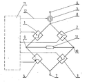
An output circuit of a stimulator, generating bipolar pulses of current, finding application in diagnosis and therapy in medicine. The invention consists in applying, in the output circuit of a stimulator, one voltage-controlled current generator /5/ being switched on between the first bus-bar /6/ and a bridge comprising four electronic keys /1/, /2/, /3/ and /4/, which is with the opposite end connected to the other bus-bar /7/. The two remaining points /9/ and /10/ of the bridge constitute the output of the stimulator, whereto the impedance /13/ of a patient is connected.
The appropriate sequence of the control run as set up from a control system /11/ makes a two-directional pulse of current flow through the impedance of a patient.
Such a solution ensures preferable symmetry of the output pulse with regard to the shape and load of the both phases, and its stability in time as well as it facilitates the process of aligning the stimulator.
Description
- The subject of the invention is an output circuit of a stimulator, generating bipolar pulses of current, to be applied in diagnosis and in therapy in medicine.
- There are known solutions of stimulator output circuits generating bipolar pulses of current, for instance from the Polish specification No. 91456 and from the US specification No. 3,924,641.
- The first solution comprises two current generators having the two terminals in common, coupled to one bus-bar, while the others provide a stimulator output being connected to load impedance. The output terminals are being alternately keyed to the other bus-bar, what enables the current flow through the load in both directions.
- The other solution comprises current generators connected in series with two electronic keys and further on connected to the first bus-bar, the other terminals of bus-bars being the output of a stimulator, and via two keys being coupled to the other bus-bar.
- Subsequent switching on the alternate pairs of keys makes the current flow through the load impedance in two directions.
- In the hitherto-known solutions the attainment of symmetry of shape and symmetry of load of the both halves of the pulse, being necessary for preferable applications, requires precise aligning of current generators in the two branches of the output circuit. It makes the operation of aligning significantly more difficult, and it does not ensure a long-term stability of the output pulse symmetry.
- In order to attain a preferable symmetry of shape and load of the output pulse and the simplicity of aligning in the output circuit, there was applied one, voltage-controlled, current generator co-operating with a bridge comprising four electronic keys.
- In the output circuit of the stimulator as per this present invention, the symmetry of the bipolar pulse of current is ensured by the application of one, voltage-controlled, current generator.
- The current generator is switched on between the first bus-bar and connected into the transition point of input of the two keys, the outputs of which, being the output of the stimulator, join the output of the two subsequent keys. Their inputs join the other bus-bar. Due to operation of signals controlled by impedance of a patient, there occurs a flow of the two-directional pulses of current, being symmetrical as far as the shape and also the load of the both halves is concerned. Such a solution of the output circuit ensures minimum interference in recording action potentials during stimulation and minimum of electrochemical phenomena in electrodes as well as it facilitates the process of aligning of the stimulator.
- The subject of the invention will be disclosed in more detail on the basis of the example of embodiment as shown in the drawing, which is being a block diagram of its preferable practical realization.
- A
current generator 5 is switched on between the first bus-bar 6 and atransition point 8 of the inputs ofelectronic keys 1 and 2. Theoutputs keys bar 7. Thecurrent generator 5 andelectronic keys control system 11. - The output circuit is being activated out of the
control system 11, which, for the time of pulse, sets the amplitude of the output current by means of the rate ofvoltage 12. At the same time, for the pre-set time interval, there are switched on theelectronic keys 1 and 3 in parallel branches of bridge, and then theelectronic keys - In the first phase of a pulse, current flows from the bus-
bar 6 through thecurrent generator 5, key 1,output point 9,impedance 13 of a patient,output point 10,key 3 to the bus-bar 7. - In the second phase of a pulse, current flows from the bus-
bar 6 through thecurrent generator 5,key 2,output point 10,impedance 13 of a patient,output point 9,key 4 to the bus-bar 7. It can be noticed that the direction of the current flow through theimpedance 13 of a patient in the second phase of a pulse is contrary to that in the first phase, and at ensuring the stability of amplitude of the current being generated by thecurrent generator 5 and at precise countdown of the duration time of the both phases of the pulse, there is preserved the symmetry of shape and the zero resultant load, flowing through theimpedance 13 of a patient. - The solution as per this present invention can be applied in all output circuits of stimulators, particularly of a cardiac muscle, where it is important to satisfy the condition of zero resultant load, flowing through the impedance of a tissue, at preserving the short duration time of the output pulse.
Claims (1)
- An output circuit of a stimulator, particularly for biomedical application, activated by a control system comprising a controlled current generator and four electronic keys, characterized in that a current generator /5/ is switched on between the first bus-bar /6/, and the input of the two keys /1/ and /2/, being connected in a transition point /8/, the outputs /9/ and /10/ of the said keys being the output of the stimulator, join the outputs of the two subsequent keys /4/ and /3/, and the inputs of the said keys join the other bus-bar /7/.
Applications Claiming Priority (2)
| Application Number | Priority Date | Filing Date | Title |
|---|---|---|---|
| PL268120 | 1987-10-07 | ||
| PL1987268120A PL156131B1 (en) | 1987-10-07 | 1987-10-07 | Stimulator's output circuitry |
Publications (1)
| Publication Number | Publication Date |
|---|---|
| EP0315768A2 true EP0315768A2 (en) | 1989-05-17 |
Family
ID=20038407
Family Applications (1)
| Application Number | Title | Priority Date | Filing Date |
|---|---|---|---|
| EP88116001A Withdrawn EP0315768A2 (en) | 1987-10-07 | 1988-09-28 | Output circuit of a stimulator |
Country Status (2)
| Country | Link |
|---|---|
| EP (1) | EP0315768A2 (en) |
| PL (1) | PL156131B1 (en) |
Cited By (7)
| Publication number | Priority date | Publication date | Assignee | Title |
|---|---|---|---|---|
| WO1991015262A1 (en) * | 1990-03-30 | 1991-10-17 | Medisan S.R.L. | A method for the electrical stimulation of a group of muscles in order to improve their appearance, and apparatus for carrying out the method |
| WO1998039060A1 (en) * | 1997-03-05 | 1998-09-11 | Physio-Control Manufacturing Corporation | H-bridge circuit for generating a high-energy biphasic waveform in an external defibrillator |
| US6175765B1 (en) | 1997-03-05 | 2001-01-16 | Medtronic Physio-Control Manufacturing Corp. | H-bridge circuit for generating a high-energy biphasic waveform in an external defibrillator |
| US6963773B2 (en) | 1997-03-05 | 2005-11-08 | Medtronic Physio-Control Manufacturing Corp. | H-bridge circuit for generating a high-energy biphasic waveform in an external defibrillator using single SCR and IGBT switches in an integrated package |
| US6965796B2 (en) | 2002-03-11 | 2005-11-15 | Medtronic Physio-Control Manufacturing Corp. | Method and apparatus for self-test of defibrillation and pacing circuits including a patient isolation switch |
| US6968230B2 (en) | 2002-06-26 | 2005-11-22 | Medtronic Physio-Control Manufacturing Corp | H-bridge circuit for generating a high-energy biphasic and external pacing waveform in an external defibrillator |
| US7096062B2 (en) | 2002-03-11 | 2006-08-22 | Medtronic Physio-Control Manufacturing Corp. | Method for self-test of defibrillation and pacing circuits including a patient isolation switch |
-
1987
- 1987-10-07 PL PL1987268120A patent/PL156131B1/en unknown
-
1988
- 1988-09-28 EP EP88116001A patent/EP0315768A2/en not_active Withdrawn
Cited By (10)
| Publication number | Priority date | Publication date | Assignee | Title |
|---|---|---|---|---|
| WO1991015262A1 (en) * | 1990-03-30 | 1991-10-17 | Medisan S.R.L. | A method for the electrical stimulation of a group of muscles in order to improve their appearance, and apparatus for carrying out the method |
| US5433737A (en) * | 1990-03-30 | 1995-07-18 | Medisan S.R.L. | Method for the electrical stimulation of a group of muscles in order to improve their appearance, and apparatus for carrying out the method |
| WO1998039060A1 (en) * | 1997-03-05 | 1998-09-11 | Physio-Control Manufacturing Corporation | H-bridge circuit for generating a high-energy biphasic waveform in an external defibrillator |
| US6041254A (en) * | 1997-03-05 | 2000-03-21 | Physio-Control Manufacturing Corporation | H-bridge circuit for generating a high-energy biphasic waveform in an external defibrillator and further including a protective component that has both inductive and resistive properties |
| US6175765B1 (en) | 1997-03-05 | 2001-01-16 | Medtronic Physio-Control Manufacturing Corp. | H-bridge circuit for generating a high-energy biphasic waveform in an external defibrillator |
| US6477413B1 (en) | 1997-03-05 | 2002-11-05 | Medtronic Physio-Control Manufacturing Corp. | H-bridge circuit for generating a high-energy biphasic waveform in an external defibrillator |
| US6963773B2 (en) | 1997-03-05 | 2005-11-08 | Medtronic Physio-Control Manufacturing Corp. | H-bridge circuit for generating a high-energy biphasic waveform in an external defibrillator using single SCR and IGBT switches in an integrated package |
| US6965796B2 (en) | 2002-03-11 | 2005-11-15 | Medtronic Physio-Control Manufacturing Corp. | Method and apparatus for self-test of defibrillation and pacing circuits including a patient isolation switch |
| US7096062B2 (en) | 2002-03-11 | 2006-08-22 | Medtronic Physio-Control Manufacturing Corp. | Method for self-test of defibrillation and pacing circuits including a patient isolation switch |
| US6968230B2 (en) | 2002-06-26 | 2005-11-22 | Medtronic Physio-Control Manufacturing Corp | H-bridge circuit for generating a high-energy biphasic and external pacing waveform in an external defibrillator |
Also Published As
| Publication number | Publication date |
|---|---|
| PL268120A1 (en) | 1989-04-17 |
| PL156131B1 (en) | 1992-02-28 |
Similar Documents
| Publication | Publication Date | Title |
|---|---|---|
| US5097833A (en) | Transcutaneous electrical nerve and/or muscle stimulator | |
| US3563247A (en) | Bidirectional heart stimulator | |
| US4595010A (en) | Electrical muscle stimulator | |
| US3096768A (en) | Electrotherapy system | |
| EP0660737B1 (en) | Arrangement for controlling a pacemaker | |
| US4167190A (en) | Pulse dosage control unit for tissue stimulation system | |
| JPS62101249A (en) | Electric stimulator | |
| EP0315768A2 (en) | Output circuit of a stimulator | |
| US3623486A (en) | Double rate demand pacemaker | |
| US4280504A (en) | Device for treatment with interference currents | |
| US3881494A (en) | Electro pulse arthritic physiotherapy system | |
| DE3067650D1 (en) | Polyvalent implantable cardiac pacemaker | |
| CN110337313A (en) | Device and method for the sense physiological signals during stimulation therapy | |
| US3295528A (en) | Electrical therapeutic equipment | |
| GB1419532A (en) | Demand inhibited cardiac pacemaker | |
| US6633778B2 (en) | High-energy, high-frequency pulse defibrillator | |
| CN115671549B (en) | Low-power consumption electric stimulation method and device | |
| RU2149040C1 (en) | Electrostimulator | |
| RU2066554C1 (en) | Gastroenteric tract electrostimulator | |
| SU891173A2 (en) | Device for exciting ultrasonic field in liquid | |
| KR100245133B1 (en) | Low frequency therapeutic apparatus | |
| SU1567212A1 (en) | Electrostimulator | |
| SU1616678A1 (en) | Method and apparatus for assisted blood circulation | |
| RU2089236C1 (en) | Electrostimulator | |
| RU2021830C1 (en) | Multichannel electric stimulator |
Legal Events
| Date | Code | Title | Description |
|---|---|---|---|
| PUAI | Public reference made under article 153(3) epc to a published international application that has entered the european phase |
Free format text: ORIGINAL CODE: 0009012 |
|
| AK | Designated contracting states |
Kind code of ref document: A2 Designated state(s): DE FR IT |
|
| STAA | Information on the status of an ep patent application or granted ep patent |
Free format text: STATUS: THE APPLICATION HAS BEEN WITHDRAWN |
|
| 18W | Application withdrawn |
Withdrawal date: 19890712 |
|
| R18W | Application withdrawn (corrected) |
Effective date: 19890712 |