EP0316005A2 - Figure encoder - Google Patents
Figure encoder Download PDFInfo
- Publication number
- EP0316005A2 EP0316005A2 EP88118834A EP88118834A EP0316005A2 EP 0316005 A2 EP0316005 A2 EP 0316005A2 EP 88118834 A EP88118834 A EP 88118834A EP 88118834 A EP88118834 A EP 88118834A EP 0316005 A2 EP0316005 A2 EP 0316005A2
- Authority
- EP
- European Patent Office
- Prior art keywords
- closed
- encoder
- extracting
- image memory
- figures
- Prior art date
- Legal status (The legal status is an assumption and is not a legal conclusion. Google has not performed a legal analysis and makes no representation as to the accuracy of the status listed.)
- Withdrawn
Links
Images


Classifications
-
- G—PHYSICS
- G06—COMPUTING; CALCULATING OR COUNTING
- G06T—IMAGE DATA PROCESSING OR GENERATION, IN GENERAL
- G06T9/00—Image coding
- G06T9/20—Contour coding, e.g. using detection of edges
-
- G—PHYSICS
- G06—COMPUTING; CALCULATING OR COUNTING
- G06K—GRAPHICAL DATA READING; PRESENTATION OF DATA; RECORD CARRIERS; HANDLING RECORD CARRIERS
- G06K11/00—Methods or arrangements for graph-reading or for converting the pattern of mechanical parameters, e.g. force or presence, into electrical signal
-
- G—PHYSICS
- G06—COMPUTING; CALCULATING OR COUNTING
- G06T—IMAGE DATA PROCESSING OR GENERATION, IN GENERAL
- G06T11/00—2D [Two Dimensional] image generation
- G06T11/20—Drawing from basic elements, e.g. lines or circles
- G06T11/206—Drawing of charts or graphs
Definitions
- the present invention relates to a figure encoder for encoding figures primarily comprised of lines, such as drawings or maps, so as to facilitate registration of such figures to computers and, more particularly, to such a figure encoder especially suitable for closed figures.
- One conventional method for executing the registration of the figures is to record the figures in an image memory by means of an imaging device and to extract figure data automatically by methods of pattern recognition.
- a sufficiently high standard of accuracy in the pattern recognition has not yet been achieved, so that corrections of recognition errors which requires enormously cumbersome procedures are indispensable.
- types of images that can be handled by this method is still extremely limited.
- a figure encoder comprising: image memory means for recording images; display means for displaying the images recorded in the image memory means; pointing means for providing a way to specify a point on the images displayed on the display means; means for extracting an image of a closed figure enclosing the specified point in accordance with a coordinate of the specified point; and means for symbolizing the extracted image of the closed figure.
- a figure encoder comprising: image memory means for recording images; display means for displaying the images recorded in the image memory means; pointing means for providing a way to specify a point on the images displayed on the display means; means for detecting coordinates of end points of line segments which are indicated to be forming a single closed figure by the pointing means; means for joining the detected end points on the images recorded in the image memory means to produce the single closed figure; and means for symbolizing the extracted image of the closed figure.
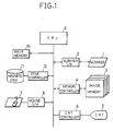
- FIG. 1 there is shown one embodiment of a figure encoder according to the present invention.
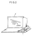
- This figure encoder comprises a scanner 1 including an imaging device for scanning images of figures such as logical diagrams or architectural drafts and producing binary image data in which lines are represented by '1' while backgrounds are represented by '0', a scanner interface 2, an image memory 2 for storing image data produced by the scanner 1, a memory controller 4, a CRT display 5, a CRT controller 6, a mouse as a pointing device 7 which provides ways to control a position of a cursor such as one shown in Fig. 2 on the CRT display 5 and specify a coordinate of the position of the cursor at a desired location when a button S is pressed down, a mouse interface 8, CPU 9 for carrying out an encoding process to be explained below, a main memory 10, a magnetic disk 11, and a disk controller 12.
- Fig. 3 shows a configuration of the image memory 3 which comprises a memory 21 for an original image scanned by the scanner 1 to be displayed on the CRT display 5, a memory 22 for thinned images, a third and memories 23 and 24 to be used in a process of extracting image data of closed figures, and a memory 25 for extracted image data of closed figures.
- the image memory 3 is connected through the memory controller 2 with the CPU 9 so that information can be exchanged freely.
- the CPU 9 to read out the image data stored in the memory 21, and perform various image processings at the CPU 9, and then store the results in an another memory is possible.
- any of the main memory 10 and the memories 23 and 24 of the image memory 3 may be utilized as temporary storing spaces, and for storing the final results any of the main memory 10, the memories 23 and 24 of the image memory 3, and the magnetic disk 11 may be used.
- Fig. 4 shows a schematic flow chart for the operation of this figure encoder.
- the operation is divided into a preliminary step and a main step.
- the preliminary step consists of the step 31 in which the original images are scanned by the scanner 1 and the image data are stored in the memory 21 of the image memory 3, and the step 32 in which a thinning of images are performed and the thinned images are stored in the memory 22 of the image memory 3.
- the main step consists of the step 33 in which the image data of closed figures are extracted from the thinned images, and the step 34 in which the extracted image data of the closed figures are symbolized.
- This symbolization can, for example, be a vectorization or other known methods.
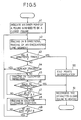
- Fig. 5 shows a detailed flow chart of the step 33.
- a point P inside a figure intended to be a closed figure is specified by an operator by means of the pointing device 7 and the coordinate of the specified point is obtained.
- tracing in eight directions from the point P is performed and when line segments are encountered the line segments are traced as shown in Fig. 6. Namely, the tracing in a direction (1) is performed first, and when a line segment is encountered that line segment is traced.
- the tracing is carried out for 4-connected figures if the thinning at the step 32 is 4-connected, or it is carried out for 8 connected figures if the thinning at the step 32 is 8-connected.
- the tracing of a line segment is performed by writing '1' to the address in the memory 23 of the image memory 3 corresponding to the coordinates of points on the line segment.
- the tracing at each point proceeds by searching a point on the line segment in the clockwise direction with respect to the direction of the tracing (step 45), which is graphically shown in Fig. 7.
- the tracing of the line segment reaches an end point instead of returning to the starting point.
- the tracing in the counterclockwise direction is also carried out (step 48) and the coordinates of an end point A found in the tracing in the clockwise direction (step 46) and an end point B found in the tracing in the counterclockwise direction (step 49) are recorded in an end points table prepared in the main memory 10 such as one shown in Fig. 8.
- the tracing in the direction (2) from the point P is carried out in the similar manner which, however, also terminates when the line segment already traced is encountered (step 44).
- the tracings in the directions (3) to (8) are carried out sequentially until the tracing in all of the eight directions are completed (step 43).
- figure data of the line segments in the memory 23 of the image memory 3 and the end points table in the main memory 10 are obtained.
- the end points originally intended to be connected are interpolated. Namely, as indicated in Fig. 8 by arrows, the end point A of the line segment a is joined with the end point B of the next line segment b , the end point A of the line segment b is joined with the end point B of the next line segment c , and so on.
- the interpolating pieces are 4-connected lines when the thinning is 4-connected, or they are 8-connected lines when the thinning is 8-connected, and they are also recorded in the memory 23 of the image memory 3.
- the resultant closed loop is stored in the memory 25 of the image memory 3 at the step 51. If necessary, this closed loop may be transformed into chain codes to be stored in the main memory 10.
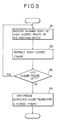
- Fig. 9 shows a flow chart for this process which replaces the flow chart shown in Fig. 5.
- a point inside one of the closed loops is specified by the operator by means of the pointing device 7, and then at the step 62 the extraction of the loop is carried out as before.
- the similar process for the other loops are carried out, one at a time (step 63 ).
- the coordinates of the specified points are stored in the main memory 10.
- the extracted loops are synthesized into a single closed figure.
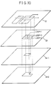
- FIG. 10 An example of this process is illustrated in Fig. 10 in which there is a closed loop divided up into three loops loop-1, loop-2, and loop-3 in the memory 22 which are separately extracted and recorded in the memory 23.
- the initially blank memory 24 is provided on which one of these loops, the loop-1 in Fig. 10, is extracted by means of the tracing from the specified point inside this loop-1.
- the tracing in one direction suffices as the figure is known beforehand as a closed one.
- the exclusive "or" operation of the figures on the memory 23 and the figures on the memory 24 is taken.
- the figure identical to the loop-1 is left on the memory 24, as shown in Fig. 10 as 24-1.
- the operator is required to specify only a point for each closed figure in the images in accordance with which the closed figures are extracted and symbolized, so that an efficiency as well as an accuracy of the figure encoding process can be improved significantly.
- a figure only partially closed by mistake and a figure subdivided into smaller fragments by mistake can be corrected into the closed figures as intended, also in accordance with a point for each closed figure specified by the operator, so that the elaborated error correction process indispensable in the prior art can now be dispensable.
- the figure encoder of the present invention is capable of handling complicated figures that cannot be dealt with by the prior art method utilizing pattern recognitions, so that this figure encoder possesses a much wider range of applicability.
Abstract
Description
- The present invention relates to a figure encoder for encoding figures primarily comprised of lines, such as drawings or maps, so as to facilitate registration of such figures to computers and, more particularly, to such a figure encoder especially suitable for closed figures.
- Recently, much efforts have been made to develop computerized administration systems for figures primarily comprised of lines, such as logical circuit diagrams, architectural drafts, or maps, by encoding such figures to store them in a data-base, and utilizing the recorded information for CAD, CAM, or other computerized operations.
- One conventional method for executing the registration of the figures is to record the figures in an image memory by means of an imaging device and to extract figure data automatically by methods of pattern recognition. In this method, a sufficiently high standard of accuracy in the pattern recognition has not yet been achieved, so that corrections of recognition errors which requires enormously cumbersome procedures are indispensable. Moreover, types of images that can be handled by this method is still extremely limited.
- Registration of those images whose complexity prohibit the application of the method just described have conventionally been accomplished by manual operations of specifying each point on the figures, representing the figures by the sets of coordinates of the specified points, and registering these sets of coordinates as figure data to computers by means of a digitizer. A variation of this method in which images are scanned by a scanner, stored in an image memory and displayed on a display on which coordinate points are specified by means of a pointing device is also conceivable. Both of these methods require a large number of points to be specified manually, which poses serious problems concerning the time required as well as the accuracy of the procedure.
- It is therefore an object of the present invention to provide a figure encoder capable of registering closed figures accurately which can be operated by simple operations.
- According to one aspect of the present invention there is provided a figure encoder, comprising: image memory means for recording images; display means for displaying the images recorded in the image memory means; pointing means for providing a way to specify a point on the images displayed on the display means; means for extracting an image of a closed figure enclosing the specified point in accordance with a coordinate of the specified point; and means for symbolizing the extracted image of the closed figure.
- According to another aspect of the present invention there is provided a figure encoder, comprising: image memory means for recording images; display means for displaying the images recorded in the image memory means; pointing means for providing a way to specify a point on the images displayed on the display means; means for detecting coordinates of end points of line segments which are indicated to be forming a single closed figure by the pointing means; means for joining the detected end points on the images recorded in the image memory means to produce the single closed figure; and means for symbolizing the extracted image of the closed figure.
- Other features and advantages of the present invention will become apparent from the following description taken in conjunction with the accompanying drawings.
-
- Fig. 1 is a block diagram of one embodiment of a figure encoder according to the present invention.
- Fig. 2 is an illustration of the figure encoder shown in Fig. 1.
- Fig. 3 is an illustration for explaining the configuration of an image memory in the figure encoder shown in Fig. 1.
- Fig. 4 is a main flow chart for the figure encoder shown in Fig. 1.
- Fig. 5 is a detailed flow chart for a figure extracting step of the flow chart shown in Fig. 4.
- Fig. 6 (a) and (b) are illustrations of examples of figures to be extracted for explaining the figure extracting step shown in Fig. 5.
- Fig. 7 (a) and (b) are illustrations of portions of the figures to be extracted for explaining the figure extracting step shown in Fig. 5.
- Fig. 8 is an illustration of an end point table to be utilized in the figure extracting step shown in Fig. 5.
- Fig. 9 is a detailed flow chart for synthetic figure extraction of the figure encoder shown in Fig. 1.
- Fig. 10 is an illustration of an example of combined figure for explaining the synthetic figure extraction shown in Fig. 9.
- Referring now to Fig. 1, there is shown one embodiment of a figure encoder according to the present invention.
- This figure encoder comprises a
scanner 1 including an imaging device for scanning images of figures such as logical diagrams or architectural drafts and producing binary image data in which lines are represented by '1' while backgrounds are represented by '0', ascanner interface 2, animage memory 2 for storing image data produced by thescanner 1, amemory controller 4, aCRT display 5, aCRT controller 6, a mouse as apointing device 7 which provides ways to control a position of a cursor such as one shown in Fig. 2 on theCRT display 5 and specify a coordinate of the position of the cursor at a desired location when a button S is pressed down, amouse interface 8, CPU 9 for carrying out an encoding process to be explained below, amain memory 10, amagnetic disk 11, and adisk controller 12. - Fig. 3 shows a configuration of the
image memory 3 which comprises a memory 21 for an original image scanned by thescanner 1 to be displayed on theCRT display 5, amemory 22 for thinned images, a third andmemories memory 25 for extracted image data of closed figures. Theimage memory 3 is connected through thememory controller 2 with the CPU 9 so that information can be exchanged freely. Thus, to read out the image data stored in the memory 21, and perform various image processings at the CPU 9, and then store the results in an another memory is possible. In a course of an image processing, any of themain memory 10 and thememories image memory 3 may be utilized as temporary storing spaces, and for storing the final results any of themain memory 10, thememories image memory 3, and themagnetic disk 11 may be used. - The operation of this figure encoder will now be explained with references to Figs. 4 to 10.
- Fig. 4 shows a schematic flow chart for the operation of this figure encoder. The operation is divided into a preliminary step and a main step. The preliminary step consists of the
step 31 in which the original images are scanned by thescanner 1 and the image data are stored in the memory 21 of theimage memory 3, and thestep 32 in which a thinning of images are performed and the thinned images are stored in thememory 22 of theimage memory 3. The main step consists of thestep 33 in which the image data of closed figures are extracted from the thinned images, and thestep 34 in which the extracted image data of the closed figures are symbolized. This symbolization can, for example, be a vectorization or other known methods. - Fig. 5 shows a detailed flow chart of the
step 33. At thestep 41, a point P inside a figure intended to be a closed figure is specified by an operator by means of thepointing device 7 and the coordinate of the specified point is obtained. Then at thestep 42, tracing in eight directions from the point P is performed and when line segments are encountered the line segments are traced as shown in Fig. 6. Namely, the tracing in a direction (1) is performed first, and when a line segment is encountered that line segment is traced. Here the tracing is carried out for 4-connected figures if the thinning at thestep 32 is 4-connected, or it is carried out for 8 connected figures if the thinning at thestep 32 is 8-connected. The tracing of a line segment is performed by writing '1' to the address in thememory 23 of theimage memory 3 corresponding to the coordinates of points on the line segment. The tracing at each point proceeds by searching a point on the line segment in the clockwise direction with respect to the direction of the tracing (step 45), which is graphically shown in Fig. 7. - When the line segment forms a completely closed loop as shown in Fig. 6 (a), the tracing in that direction terminates as the tracing returns to where the tracing of the line segment had started (step 46), and the result is stored in the
memory 25 of the image memory 3 (step 51). - On the other hand, when the line segment is not closed one in spite of the original intention to be a closed loop, such as one shown in Fig. 6 (b), the tracing of the line segment reaches an end point instead of returning to the starting point. When this happened to be the case, the tracing in the counterclockwise direction is also carried out (step 48) and the coordinates of an end point A found in the tracing in the clockwise direction (step 46) and an end point B found in the tracing in the counterclockwise direction (step 49) are recorded in an end points table prepared in the
main memory 10 such as one shown in Fig. 8. - After the tracing in the direction (1) is terminated, the tracing in the direction (2) from the point P is carried out in the similar manner which, however, also terminates when the line segment already traced is encountered (step 44). Similarly, the tracings in the directions (3) to (8) are carried out sequentially until the tracing in all of the eight directions are completed (step 43). As a result of these tracings, figure data of the line segments in the
memory 23 of theimage memory 3 and the end points table in themain memory 10 are obtained. - Next, at the
step 50 the end points originally intended to be connected are interpolated. Namely, as indicated in Fig. 8 by arrows, the end point A of the line segment a is joined with the end point B of the next line segment b, the end point A of the line segment b is joined with the end point B of the next line segment c, and so on. Here the interpolating pieces are 4-connected lines when the thinning is 4-connected, or they are 8-connected lines when the thinning is 8-connected, and they are also recorded in thememory 23 of theimage memory 3. Then the resultant closed loop is stored in thememory 25 of theimage memory 3 at thestep 51. If necessary, this closed loop may be transformed into chain codes to be stored in themain memory 10. - Next, the process that takes place when what was originally intended as a closed loop is divided up into a number of closed loops as portions of the other figures overlaps.
- Fig. 9 shows a flow chart for this process which replaces the flow chart shown in Fig. 5. At the step 61 a point inside one of the closed loops is specified by the operator by means of the
pointing device 7, and then at thestep 62 the extraction of the loop is carried out as before. The similar process for the other loops are carried out, one at a time ( step 63 ). The coordinates of the specified points are stored in themain memory 10. Then at thestep 64, the extracted loops are synthesized into a single closed figure. - An example of this process is illustrated in Fig. 10 in which there is a closed loop divided up into three loops loop-1, loop-2, and loop-3 in the
memory 22 which are separately extracted and recorded in thememory 23. To carry out the process of synthesizing these loops, the initiallyblank memory 24 is provided on which one of these loops, the loop-1 in Fig. 10, is extracted by means of the tracing from the specified point inside this loop-1. Here the tracing in one direction suffices as the figure is known beforehand as a closed one. Then the exclusive "or" operation of the figures on thememory 23 and the figures on thememory 24 is taken. As a result, since there was only the loop-1 on thememory 24, the figure identical to the loop-1 is left on thememory 24, as shown in Fig. 10 as 24-1. Next, the similar process is carried out for the loop-2 which yields the result shown in Fig. 10 as 24-2, in which the loop-1 and the loop-2 have been synthesized. By carrying out the similar process for the loop-3, the original closed figure can be reconstructed. The final result of this process is then stored in thememory 25 as before. - As explained, according to the present invention, the operator is required to specify only a point for each closed figure in the images in accordance with which the closed figures are extracted and symbolized, so that an efficiency as well as an accuracy of the figure encoding process can be improved significantly. Moreover, according to the above embodiment, a figure only partially closed by mistake and a figure subdivided into smaller fragments by mistake can be corrected into the closed figures as intended, also in accordance with a point for each closed figure specified by the operator, so that the elaborated error correction process indispensable in the prior art can now be dispensable. Furthermore, the figure encoder of the present invention is capable of handling complicated figures that cannot be dealt with by the prior art method utilizing pattern recognitions, so that this figure encoder possesses a much wider range of applicability.
- It is to be noted that the tracing of the thinned image of the line segment utilized in this embodiment for extracting the figures can be replaced by the tracing of the boundaries of the figures and the background.
- Besides this, many modifications and variations of this embodiment may be made without departing from the novel and advantageous features of the present invention. Accordingly, all such modifications and variations are intended to be included within the scope of the appended claims.
Claims (10)
image memory means for recording images;
display means for displaying the images recorded in the image memory means;
pointing means for providing a way to specify a point on the images displayed on the display means;
means for extracting an image of a closed figure enclosing the specified point in accordance with a coordinate of the specified point; and
means for symbolizing the extracted image of the closed figure.
means for thinning the images recorded in the image memory means; and
means for tracing the contour of a thinned image of the closed figure enclosing the specified point.
means for detecting coordinates of end points of line segments which are indicated to be forming a single closed figure by the pointing means; and
means for interpolating between the detected end points on the images recorded in the image memory means to produce an image of the single closed figure.
image memory means for recording images;
display means for displaying the images recorded in the image memory means;
pointing means for providing a way to specify a point on the images displayed on the display means;
means for detecting coordinates of end points of line segments which are indicated to be forming a single closed figure by the pointing means;
means for interpolating between the detected end points on the images recorded in the image memory means to produce the single closed figure; and
means for symbolizing the extracted image of the closed figure.
Applications Claiming Priority (2)
| Application Number | Priority Date | Filing Date | Title |
|---|---|---|---|
| JP62285902A JP2735197B2 (en) | 1987-11-12 | 1987-11-12 | Graphic input device |
| JP285902/87 | 1987-11-12 |
Publications (2)
| Publication Number | Publication Date |
|---|---|
| EP0316005A2 true EP0316005A2 (en) | 1989-05-17 |
| EP0316005A3 EP0316005A3 (en) | 1991-03-27 |
Family
ID=17697499
Family Applications (1)
| Application Number | Title | Priority Date | Filing Date |
|---|---|---|---|
| EP19880118834 Withdrawn EP0316005A3 (en) | 1987-11-12 | 1988-11-11 | Figure encoder |
Country Status (3)
| Country | Link |
|---|---|
| US (1) | US5301264A (en) |
| EP (1) | EP0316005A3 (en) |
| JP (1) | JP2735197B2 (en) |
Families Citing this family (5)
| Publication number | Priority date | Publication date | Assignee | Title |
|---|---|---|---|---|
| US5553219A (en) * | 1991-05-10 | 1996-09-03 | Fuji Xerox Co., Ltd. | Font outline and bit map generator synthesizing filling data with selected outline data or duplicate outline data |
| CN1033110C (en) * | 1992-09-01 | 1996-10-23 | 寅市和男 | Input and output device of characters, logomarks, illustrations and input and output method of same |
| US5887081A (en) * | 1995-12-07 | 1999-03-23 | Ncr Corporation | Method for fast image identification and categorization of multimedia data |
| JPH09237354A (en) * | 1996-02-29 | 1997-09-09 | Chokosoku Network Computer Gijutsu Kenkyusho:Kk | Method for transferring and displaying three-dimensional shape data |
| KR100395887B1 (en) * | 2000-10-24 | 2003-08-27 | 한국전력공사 | Auto-Recogniton method of the distribution network drawings in constructi ng the data-base at geographical information system |
Citations (2)
| Publication number | Priority date | Publication date | Assignee | Title |
|---|---|---|---|---|
| EP0083989A2 (en) * | 1982-01-08 | 1983-07-20 | Kabushiki Kaisha Toshiba | Image editing apparatus |
| EP0149457A2 (en) * | 1984-01-13 | 1985-07-24 | Kabushiki Kaisha Komatsu Seisakusho | Method of identifying contour lines |
Family Cites Families (19)
| Publication number | Priority date | Publication date | Assignee | Title |
|---|---|---|---|---|
| US4020463A (en) * | 1976-02-27 | 1977-04-26 | Recognition Equipment Incorporated | Apparatus and a method for storage and retrieval of image patterns |
| JPS5580188A (en) * | 1978-12-12 | 1980-06-17 | Nippon Telegr & Teleph Corp <Ntt> | Linear pattern coding unit |
| JPS57141779A (en) * | 1981-02-26 | 1982-09-02 | Nec Corp | Character cutout system |
| JPS58166348A (en) * | 1982-03-26 | 1983-10-01 | Dainippon Printing Co Ltd | Device for forming cutoff mask for printing |
| US4566126A (en) * | 1982-04-30 | 1986-01-21 | Fuji Electric Company, Ltd. | Pattern discriminator |
| JPS5947666A (en) * | 1982-09-13 | 1984-03-17 | Dainippon Screen Mfg Co Ltd | Data compressing method of binary picture |
| JPS5999576A (en) * | 1982-11-30 | 1984-06-08 | Toshiba Corp | Storage and retrieval system device for picture information |
| US4783829A (en) * | 1983-02-23 | 1988-11-08 | Hitachi, Ltd. | Pattern recognition apparatus |
| JPS59191667A (en) * | 1983-04-16 | 1984-10-30 | Dainippon Printing Co Ltd | Picture data converting system |
| DE3479254D1 (en) * | 1983-07-04 | 1989-09-07 | Karow Rubow Weber Gmbh | Method for automatically digitizing the contours of line graphics, e.g. characters |
| JPS60111490A (en) * | 1983-11-22 | 1985-06-17 | 富士通株式会社 | Printed board pattern drawing automatically digitizing device |
| JPS60196856A (en) * | 1984-03-20 | 1985-10-05 | Olympus Optical Co Ltd | Picture retrieval registering system |
| JPS61221968A (en) * | 1985-03-28 | 1986-10-02 | Fuji Electric Co Ltd | Drawing reader |
| US4809201A (en) * | 1985-12-02 | 1989-02-28 | Schlumberger Systems, Inc. | Graphic display region defining technique |
| JP2587812B2 (en) * | 1986-03-10 | 1997-03-05 | 日本電信電話株式会社 | Figure extraction method |
| GB2190560B (en) * | 1986-05-08 | 1990-06-20 | Gen Electric Plc | Data compression |
| JPS62269276A (en) * | 1986-05-19 | 1987-11-21 | Nippon Telegr & Teleph Corp <Ntt> | Interactive graphic inputting system |
| JPH0785271B2 (en) * | 1986-06-27 | 1995-09-13 | 株式会社日立製作所 | Shape modeling method |
| US4817187A (en) * | 1987-02-19 | 1989-03-28 | Gtx Corporation | Apparatus and method for vectorization of incoming scanned image data |
-
1987
- 1987-11-12 JP JP62285902A patent/JP2735197B2/en not_active Expired - Fee Related
-
1988
- 1988-11-11 EP EP19880118834 patent/EP0316005A3/en not_active Withdrawn
-
1992
- 1992-07-16 US US07/913,985 patent/US5301264A/en not_active Expired - Fee Related
Patent Citations (2)
| Publication number | Priority date | Publication date | Assignee | Title |
|---|---|---|---|---|
| EP0083989A2 (en) * | 1982-01-08 | 1983-07-20 | Kabushiki Kaisha Toshiba | Image editing apparatus |
| EP0149457A2 (en) * | 1984-01-13 | 1985-07-24 | Kabushiki Kaisha Komatsu Seisakusho | Method of identifying contour lines |
Non-Patent Citations (2)
| Title |
|---|
| PATTERN RECOGNITION, vol. 20, no. 3, 1987, pages 273-280, Elsmford, NY, US; N. BABAGUCHI et al.: "Curvedness of a line picture" * |
| SYSTEMS AND COMPUTERS IN JAPAN, vol. 17, no. 7, 1986, pages 49-59; S. SHIMADA et al.: "Representation and interpretation of overlapped line segments for automatic recognition of LSI cell drawings" * |
Also Published As
| Publication number | Publication date |
|---|---|
| JP2735197B2 (en) | 1998-04-02 |
| JPH01126774A (en) | 1989-05-18 |
| US5301264A (en) | 1994-04-05 |
| EP0316005A3 (en) | 1991-03-27 |
Similar Documents
| Publication | Publication Date | Title |
|---|---|---|
| EP0534446A2 (en) | System with approximation means for recognizing graphical elements in a drawing | |
| JPS5923467B2 (en) | Position detection method | |
| JPS63145577A (en) | Pattern data generating method | |
| CN113554757A (en) | Three-dimensional reconstruction method and system for workpiece track based on digital twinning | |
| US5301264A (en) | Figure encoder | |
| US5493639A (en) | Drawing processing with flexible accomodation of character strings | |
| US6178264B1 (en) | Image cutout method and apparatus | |
| EP1202213A2 (en) | Document format identification apparatus and method | |
| US5168553A (en) | Line figure encoder | |
| JP2000105813A (en) | Image connection system and recording medium where image connecting program is recorded | |
| US5003495A (en) | Method and apparatus for scanning, storing and reproducing artwork | |
| JP2636736B2 (en) | Fingerprint synthesis device | |
| JP3657725B2 (en) | Line figure image processing method | |
| JP2803736B2 (en) | Character recognition method | |
| JP2824372B2 (en) | Report recognition device | |
| JP2773127B2 (en) | Image editing method | |
| KR20230148999A (en) | High-resolution image stitching method for semiconductor defect inspection | |
| JP2838556B2 (en) | Image processing device | |
| JP3967400B2 (en) | Object recognition device | |
| JP3080080B2 (en) | Image connection system and recording medium storing image connection program | |
| JPH07129745A (en) | Method and device for connecting image data | |
| JP2019219772A (en) | Template registration device and corresponding area specifying device | |
| JPH06259554A (en) | Picture outline extracting device | |
| JP2801246B2 (en) | Character processing apparatus and method | |
| JPS61165188A (en) | Symbol recognizing system |
Legal Events
| Date | Code | Title | Description |
|---|---|---|---|
| PUAI | Public reference made under article 153(3) epc to a published international application that has entered the european phase |
Free format text: ORIGINAL CODE: 0009012 |
|
| 17P | Request for examination filed |
Effective date: 19881111 |
|
| AK | Designated contracting states |
Kind code of ref document: A2 Designated state(s): DE FR GB IT NL |
|
| PUAL | Search report despatched |
Free format text: ORIGINAL CODE: 0009013 |
|
| AK | Designated contracting states |
Kind code of ref document: A3 Designated state(s): DE FR GB IT NL |
|
| 17Q | First examination report despatched |
Effective date: 19930430 |
|
| STAA | Information on the status of an ep patent application or granted ep patent |
Free format text: STATUS: THE APPLICATION IS DEEMED TO BE WITHDRAWN |
|
| 18D | Application deemed to be withdrawn |
Effective date: 19931111 |