EP0316144A2 - Method and apparatus for classifying graphics segments to facilitate pick and display operation - Google Patents
Method and apparatus for classifying graphics segments to facilitate pick and display operation Download PDFInfo
- Publication number
- EP0316144A2 EP0316144A2 EP88310510A EP88310510A EP0316144A2 EP 0316144 A2 EP0316144 A2 EP 0316144A2 EP 88310510 A EP88310510 A EP 88310510A EP 88310510 A EP88310510 A EP 88310510A EP 0316144 A2 EP0316144 A2 EP 0316144A2
- Authority
- EP
- European Patent Office
- Prior art keywords
- segment
- display
- axis
- segments
- display device
- Prior art date
- Legal status (The legal status is an assumption and is not a legal conclusion. Google has not performed a legal analysis and makes no representation as to the accuracy of the status listed.)
- Granted
Links
Images
Classifications
-
- G—PHYSICS
- G06—COMPUTING; CALCULATING OR COUNTING
- G06F—ELECTRIC DIGITAL DATA PROCESSING
- G06F3/00—Input arrangements for transferring data to be processed into a form capable of being handled by the computer; Output arrangements for transferring data from processing unit to output unit, e.g. interface arrangements
- G06F3/01—Input arrangements or combined input and output arrangements for interaction between user and computer
- G06F3/048—Interaction techniques based on graphical user interfaces [GUI]
- G06F3/0484—Interaction techniques based on graphical user interfaces [GUI] for the control of specific functions or operations, e.g. selecting or manipulating an object, an image or a displayed text element, setting a parameter value or selecting a range
- G06F3/04842—Selection of displayed objects or displayed text elements
-
- G—PHYSICS
- G06—COMPUTING; CALCULATING OR COUNTING
- G06T—IMAGE DATA PROCESSING OR GENERATION, IN GENERAL
- G06T11/00—2D [Two Dimensional] image generation
Definitions
- This invention relates to a method and apparatus for classifying graphics segments to facilitate pick and display operation.
- a computer-aided design (CAD) system may comprise a data base memory for storing information relating an an article whose design is being developed, e.g. an integrated circuit, a program memory for storing programs that are used in developing the design, a processor which acts on the stored information relating to the article in accordance with the stored programs for modifying the stored information, and a user interface whereby the user is able to control operation of the CAD system.
- the user interface comprises an input device for loading information into the data base memory, display apparatus for providing a display of the article represented by the contents of the data base memory, or some portion thereof, and a manipulation device for controlling the manner in which the stored programs act on the contents of the data base memory.
- the CAD system may also include, or be connected to, a printer or plotter for providing a hard copy of the display provided by the display apparatus.
- a CAD system may employ a display system in which a picture to be displayed is composed of objects and data representing the objects is stored in the data base memory in the form of segments.
- a segment is a logically related collections of picture primitives that are operated upon as a single entity.
- Each segment comprises a segment header portion which includes a unique identification number, a segment body portion which includes picture primitives, for example a list of vectors specified by their end points in a rectangular Cartesian coordinate system, and a segment end portion. All segments in a picture are normally linked together into a structure called the display list. To locate any segment the display list is traversed until the desired segment is located.
- a search is conducted in which each segment of the picture is examined in turn until a segment located under the cursor is found.
- This search may be accomplished by using the contents of the data memory to draw a virtual, i.e., undisplayed, image in the address space of the display apparatus and carrying out a logical AND operation between the locations that are pixilated during this drawing operation and the location of the cursor.
- N/2 segments need to be tested for cursor coverage, where N is the number of segments. Locating the cursor directly over the object of interest can be difficult. Therefore, pick operations can also be performed to find segments located within an area around the cursor. The area in which segments can be found is called a pick aperture.
- the display is not created directly from the segments stored in the data base memory, by continuously drawing a succession of vectors on the display screen. Rather, the contents of the data base memory are used to create a virtual image of the vectors in the address domain of a frame buffer and the contents of the frame buffer are used to drive a raster scan display device which displays the contents of the frame buffer. If the address space of the frame buffer is larger than the address domain occupied by the virtual image, the entire contents of the data base memory are represented in the display. If it is desired to display an object at an enlarged scale, the contents of the frame buffer must be changed.
- the contents of the data base memory are used to create a vir tual image representing the entire contents of the data base memory over an enlarged address domain, with only the object of interest being within the address space of the frame buffer. Again, this is a time-consuming operation and may be disturbing to the user of the CAD system.
- one quarter of the information content of the display is associated with values of X that are less than /X - 0.67 s.d.X (where s.d.X is the standard deviation in the X direction), one quarter with values of X between /X - 0.67 s.d.X and /X, one quarter with values of X between /X and /X + 0.67 s.d.X, and one quarter with values of X greater than /X + 0.67 s.d.X.
- one quarter of the information content of the display is associated with each of the four bands of the display characterized respectively by values of Y less than /Y - 0.67 s.d.Y, between /Y - 0.67 s.d.Y and /Y, between /Y and /Y + 0.67 s.d.Y, and greater than /Y + 0.67 s.d.Y.
- a preferred embodiment of the present invention is a display system which comprises a data base memory for storing data representing a picture, a display device for displaying the picture, and manipulation means for causing the display device to display a cursor at a position which is under user control.
- the picture is composed of objects and each object is represented in the data base memory by a segment which represents both the object and the position of the object in the picture.
- a pointer which divides the address domain of the display device into at least two regions, is generated.
- the manipulation means provide a signal which identifies the region of the picture in which the cursor is positioned, and this signal is compared with the contents of the data base memory to facilitate selection of an object which lies in the identified region of the picture.
- the CAD system illustrated in FIG. 1 comprises a data base memory 16 containing files 16A, 16B, ..., and a processor 18 for operating on the data contained in the data base files in accordance with programs stored in a program memory 20.
- the processor operates on the data by transferring data between files and carrying out other operations on data contained in one of the files, which is referred to herein as the display file.
- a user interface includes an input device 24 for loading data into the data base memory, and a manipulation device 26, such as a mouse, for controlling the nature of the operations performed on the data stored in the data base memory.
- the user interface also includes display apparatus which comprises a frame buffer 30 and a raster-scan cathode ray tube display device 28 which provides a display based on the contents of the frame buffer 30.
- the display that is provided on the display device is a bit-mapped representation of the contents of the frame buffer 30.
- An output device 32 such as a plotter, is connected to the CAD system for providing a hard copy of the display provided by the display device.
- the information that is stored in the data base memory is in the form of graphic segments.
- Each segment has a header portion which includes a unique identification number segment, a body portion which includes a list of vectors, and an end portion.
- the header portion of each data segment stored in the file 16A includes a segment classification code which represents the location of the object in the picture. The manner in which the segment classification code is derived is explained below.
- the address domain of the display apparatus is divided into regions of substantially equal information content.
- the processor calculates and stores the mean, /X, of the picture. If the jth vector of the ith segment in the file 16A is identified by the coordinates of the vector end-points (X1ij, Y1ij) and (X2ij, Y2ij), the value of /X is given by 1/N*Sum(i,j) (X1ij + X2ij)/2 where N is the total number of vectors in the picture and Sum(i,j) represents summation over all i and all j.
- s.d.X the standard deviation s.d.X of the X position is calculated and stored.
- the value of s.d.X is given by (Sum(i,j)((X1ij+X2ij)/2-/X**2)**1/2 Techniques for calculating s.d.X without previous knowledge of /X are described in the literature.
- values of /Y and s.d.Y are calculated from the values of Y1ij and Y2ij and are stored for the picture. Assuming the information content of the picture varies substantially in accordance with a Gaussian function, the picture can now be divided into as many regions of equal information content as desired.
- the processor 18 utilizes the stored values to generate pointers at /X, /X ⁇ 0.67 s.d.X, /Y, and /Y ⁇ 0.67 s.d.Y.
- 16 regions each of which contains approximately one-sixteenth of the information stored in file 16A of the data base memory, as represented by the lengths of the vectors, are defined in the address domain of the display apparatus.
- the locations of these pointers are illustrated in FIG. 3 by vertical and horizontal region divider lines, but these lines would not normally be displayed.
- Each region is identified in the CAD system by a number in the range from 0 to 15. The numbers may be distributed as shown in FIG. 3, although they do not appear in the display.
- the segment classification code has 16 bits which may be regarded as being numbered from 0 through 15 from left to right. If part of an object appears within the boundary of the kth region, the kth bit of the segment classification code is logical 1, and otherwise it is logical 0. The segment classification code therefore is not restricted to identifying a single region.
- the mouse In order to pick a segment that is to be operated on, the mouse is manipulated until the cursor is over the object that is represented by the segment.
- the processor generates a 16 bit cursor classification code. If the cursor is located in the kth region of the display, the kth bit of the cursor classification code is logical 1 and all other bits are logical 0.
- a logical AND operation is performed on a bit by bit basis using the cursor classification code and the segment classification code. Segments for which the AND operation does not yield a logical 1 for the kth bit are transferred to file 16B and are not examined further.
- File 16A then contains only the segments for which the logical AND operation yielded a logical 1 for the kth bit.
- the processor examines each of the segments remaining in file 16A in order to identify the one that is under the cursor. This examination is conducted in conventional fashion. On finding the segment that is under the cursor, the desired pick operation has been completed. However, this has been done without its having been potentially necessary to examine all the segments. On average, and assuming that each segment covers only one region of the picture, only N/32 segments need to be tested for cursor coverage, which represents a reduction by a factor of 16. In general, if the picture is divided into M regions of equal information content, the time required to locate the segment under the cursor is reduced by a factor of M. In almost all practical pictures some segments will cover more than one region, but most segments will cover only one region.
- C(i) be the number of segments that cover i regions.
- the average number of searches required to perform a pick operation is Sum(C(i) * i)/2M. This reduces to N/2M when all segments cover only one region.
- pick operations can be performed with an aperture by searching each region the pick aperture covers. In most CAD applications the number of searches required to locate a segment during a pick operation will closely approximate N/2M for a reasonably small number of regions such as 16 and a normal sized pick aperture.
- the user may cause the object represented by the segment to be displayed. This may be facilitated by transferring all the other segments from file 16A of the data base memory to another file, e.g. file 16B.
- file 16B another file
- the contents of file 164 are thereby further reduced, and accordingly it takes much less time to process the contents of the file 16A and load the frame buffer.
- the user may wish to examine a portion of the entire picture, rather than a single object, at an enlarged scale.
- the user may wish to examine an object of interest against a background of other objects in the immediate vicinity of the object of interest.
- the cursor is positioned over the object of interest and the processor determines which region contains the object of interest.
- the user may then instruct the processor to display all objects that lie in that region, and possibly also the objects that lie in one or more adjacent regions.
- the segments representing the selected objects are retained in file 16A and the remaining segments are transferred to file 16B.
- the processor draws a virtual image of the vectors represented by the segments in file 16A in the address space of the frame buffer, and that portion of the virtual image which lies in the address domain of the display apparatus is loaded into the frame buffer and is used to drive the display device.
- An enlarged display of the selected objects is thereby provided. If the detail of the enlarged display is insufficient, the user can repeat the pick operation by reference to the new pointers and select one or more regions of the enlarged display for display at a still larger scale. If the operator then wishes to select a single object for display or modification, this can be accomplished using the procedure that was previously described.
- Either file of the data base memory may be selected for loading the frame buffer. If, for example, the user initially selected region 5 and caused regions 0-4 and 6-16 to be transferred to file 16B, and then determined that he had made a mistake and that the object of interest was not in fact in region 5, the user may then select file 16B as the display file. New values for the pointers are computed based on the contents of file 16B, i.e., the original contents of file 16A but without region 5, and the values will normally be different from the values calculated on the basis of the contents of file 16A.
- Determining which regions of the picture contain a given segment is generally quite easy, because most segments contian only the poly-line primitive. In this case, if all the vector end points are in the same region, the segment covers only that region, and the segment classification code contains only one logical 1, at the position corresponding to the number of the region.
- the segment classification code for a segment is created by comparing the values of X and Y in the vector list for the segment with the values of /X, /X ⁇ 0.67 s.d.X, /Y and /Y ⁇ 0.67 s.d.Y, and thereby determining the regions that contain the end points of the vectors.
- a simpler procedure is to mark the segment containing the line segment as covering the superset ⁇ 0,1,4,5 ⁇ rather than calculating which set ⁇ 0,1,5 ⁇ or ⁇ 0,4,5 ⁇ is the actual segment classification set.
- Calculating a superset for the actual coverage set of a segment degrades the speed of future operations such as picks but reduces the computation complexity of determining which regions a segment actually covers. The speed of subsequent operations will be reduced by a factor of one plus the ratio of the number of extra regions marked as covered compared to the actual number of regions covered. For configurations which seldom occur, and assuming a picture is being dynamically modified, marking supersets of actual coverage sets for segments reduces the overall time required by the user to manipulate the picture.
- the present inven strictlytion is not restricted to the particular embodiment that has been described and illustrated, and that variations may be made therein without departing from the scope of the invention as defined in the appended claims and equivalents thereof.
- the segments that are used to calculate the values of the pointers represent objects that are distributed over the entire screen, since they may be contained in a window against a background that is not divided. There may be multiple windows against a given background, and each may contain a display of objects represented by a set of segment, with the values of the pointers for each set being calculated separately.
- the picture might not be composed only of vectors, and may include tiled areas.
- the value of /X is given by A Sum(i,j) (X1ij+X2ij)/2 + B Sum(m) (AmXm) where A and B are weighting factors, and the value of s.d.X is given by C(Sum(i,j) (X1ij+X2ij)/2-/X)**2)**1/2 +D(Sum(m) (AmXm-/X)**2)**1/2 where C and D are weighting factors.
- the values of /Y and s.d.Y are calculated in similar fashion.
- the values of the weighting factors depend on the relative times taken to draw a typical vector and tile a typical solid area. If the pick operation is performed by a method that does not involve drawing a virtual image of the contents of the display file, it may not be appropriate to use the length of the vectors, which determines the time taken to draw the vectors, as a measure of information content.
Abstract
Description
- This invention relates to a method and apparatus for classifying graphics segments to facilitate pick and display operation.
- A computer-aided design (CAD) system may comprise a data base memory for storing information relating an an article whose design is being developed, e.g. an integrated circuit, a program memory for storing programs that are used in developing the design, a processor which acts on the stored information relating to the article in accordance with the stored programs for modifying the stored information, and a user interface whereby the user is able to control operation of the CAD system. Typically, the user interface comprises an input device for loading information into the data base memory, display apparatus for providing a display of the article represented by the contents of the data base memory, or some portion thereof, and a manipulation device for controlling the manner in which the stored programs act on the contents of the data base memory. The CAD system may also include, or be connected to, a printer or plotter for providing a hard copy of the display provided by the display apparatus.
- A CAD system may employ a display system in which a picture to be displayed is composed of objects and data representing the objects is stored in the data base memory in the form of segments. A segment is a logically related collections of picture primitives that are operated upon as a single entity. Each segment comprises a segment header portion which includes a unique identification number, a segment body portion which includes picture primitives, for example a list of vectors specified by their end points in a rectangular Cartesian coordinate system, and a segment end portion. All segments in a picture are normally linked together into a structure called the display list. To locate any segment the display list is traversed until the desired segment is located.
- In use of a CAD system, it is frequently necessary to carry out operations on an object. These operations might include altering the object or displaying the object at a enlarged scale so that the user can discern features of the object that cannot be clearly seen when the display represents the entire contents of the data base memory. The operation of selecting, or picking, the data segment that represents an object of interest is performed by displaying a cursor which is movable under user control by use of the manipulation device, which may be a joystick, a mouse or other manipulation device. If the user wishes to select the segment representing a particular object, the cursor is placed over the object on the display and a pick operation is performed. The segment may now be the subject of future operations, e.g. display at an enlarged scale. To locate the segment under the cursor during a pick operation a search is conducted in which each segment of the picture is examined in turn until a segment located under the cursor is found. This search may be accomplished by using the contents of the data memory to draw a virtual, i.e., undisplayed, image in the address space of the display apparatus and carrying out a logical AND operation between the locations that are pixilated during this drawing operation and the location of the cursor. On average, N/2 segments need to be tested for cursor coverage, where N is the number of segments. Locating the cursor directly over the object of interest can be difficult. Therefore, pick operations can also be performed to find segments located within an area around the cursor. The area in which segments can be found is called a pick aperture. Pick operations are time consuming, and in the case of a large data base may take up to 30 seconds to complete. Such a delay is disturbing to the user of the CAD system. However, it is not practicable to keep a running check on the identity of the segment under the cursor as the cursor is moved through the picture, since this would entail continually updating the cursor segment at a high speed.
- In a CAD system employing a segmented display, the display is not created directly from the segments stored in the data base memory, by continuously drawing a succession of vectors on the display screen. Rather, the contents of the data base memory are used to create a virtual image of the vectors in the address domain of a frame buffer and the contents of the frame buffer are used to drive a raster scan display device which displays the contents of the frame buffer. If the address space of the frame buffer is larger than the address domain occupied by the virtual image, the entire contents of the data base memory are represented in the display. If it is desired to display an object at an enlarged scale, the contents of the frame buffer must be changed. With a conventional CAD system having a segmented display, the contents of the data base memory are used to create a vir tual image representing the entire contents of the data base memory over an enlarged address domain, with only the object of interest being within the address space of the frame buffer. Again, this is a time-consuming operation and may be disturbing to the user of the CAD system.
- It has been observed that in most pictures that are displayed using a CAD system, the density with which information (represented by total vector length) is distributed over the picture area, both in the horizontal, or X, direction and in the vertical, or Y, direction, varies substantially in accordance with a Gaussian function. Therefore, half of the information content of the display is associated with values of X that are less than the value /X associated with the peak of the Gaussian function and half of the information content is associated with the values of X that are greater than /X. Furthermore, one quarter of the information content of the display is associated with values of X that are less than /X - 0.67 s.d.X (where s.d.X is the standard deviation in the X direction), one quarter with values of X between /X - 0.67 s.d.X and /X, one quarter with values of X between /X and /X + 0.67 s.d.X, and one quarter with values of X greater than /X + 0.67 s.d.X. Similarly, in the Y direction one quarter of the information content of the display is associated with each of the four bands of the display characterized respectively by values of Y less than /Y - 0.67 s.d.Y, between /Y - 0.67 s.d.Y and /Y, between /Y and /Y + 0.67 s.d.Y, and greater than /Y + 0.67 s.d.Y.
- A preferred embodiment of the present invention is a display system which comprises a data base memory for storing data representing a picture, a display device for displaying the picture, and manipulation means for causing the display device to display a cursor at a position which is under user control. The picture is composed of objects and each object is represented in the data base memory by a segment which represents both the object and the position of the object in the picture. A pointer, which divides the address domain of the display device into at least two regions, is generated. The manipulation means provide a signal which identifies the region of the picture in which the cursor is positioned, and this signal is compared with the contents of the data base memory to facilitate selection of an object which lies in the identified region of the picture.
- For a better understanding of the invention, and to show how the same may be carried into effect, reference will now be made, by way of example, to the accompanying drawings in which:
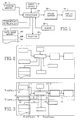
- FIG. 1 is a block diagram of a CAD system,
- FIG. 2 illustrates a typical display provided by the CAD system,
- FIG. 3 illustrates the FIG. 2 display with additional information applied thereto.
- The CAD system illustrated in FIG. 1 comprises a
data base memory 16 containingfiles processor 18 for operating on the data contained in the data base files in accordance with programs stored in aprogram memory 20. The processor operates on the data by transferring data between files and carrying out other operations on data contained in one of the files, which is referred to herein as the display file. A user interface includes aninput device 24 for loading data into the data base memory, and a manipulation device 26, such as a mouse, for controlling the nature of the operations performed on the data stored in the data base memory. The user interface also includes display apparatus which comprises aframe buffer 30 and a raster-scan cathode raytube display device 28 which provides a display based on the contents of theframe buffer 30. The display that is provided on the display device is a bit-mapped representation of the contents of theframe buffer 30. Anoutput device 32, such as a plotter, is connected to the CAD system for providing a hard copy of the display provided by the display device. - The information that is stored in the data base memory is in the form of graphic segments. Each segment has a header portion which includes a unique identification number segment, a body portion which includes a list of vectors, and an end portion. The header portion of each data segment stored in the
file 16A includes a segment classification code which represents the location of the object in the picture. The manner in which the segment classification code is derived is explained below. - In accordance with the invention, the address domain of the display apparatus is divided into regions of substantially equal information content. In the event that information content is assumed to be based on vector length, the processor calculates and stores the mean, /X, of the picture. If the jth vector of the ith segment in the
file 16A is identified by the coordinates of the vector end-points (X1ij, Y1ij) and (X2ij, Y2ij), the value of /X is given by
1/N*Sum(i,j) (X1ij + X2ij)/2
where N is the total number of vectors in the picture and Sum(i,j) represents summation over all i and all j. - In addition, the standard deviation s.d.X of the X position is calculated and stored. The value of s.d.X is given by
(Sum(i,j)((X1ij+X2ij)/2-/X**2)**1/2
Techniques for calculating s.d.X without previous knowledge of /X are described in the literature. Similarly, values of /Y and s.d.Y are calculated from the values of Y1ij and Y2ij and are stored for the picture. Assuming the information content of the picture varies substantially in accordance with a Gaussian function, the picture can now be divided into as many regions of equal information content as desired. If, for example, it is desired to divide the address domain into sixteen regions, theprocessor 18 utilizes the stored values to generate pointers at /X, /X ∓ 0.67 s.d.X, /Y, and /Y ∓ 0.67 s.d.Y. In this manner, 16 regions, each of which contains approximately one-sixteenth of the information stored infile 16A of the data base memory, as represented by the lengths of the vectors, are defined in the address domain of the display apparatus. The locations of these pointers are illustrated in FIG. 3 by vertical and horizontal region divider lines, but these lines would not normally be displayed. In fact, the CAD system shown in FIG. 1 does not have the capability of creating the auxiliary display that would be necessary to show the lines. Each region is identified in the CAD system by a number in the range from 0 to 15. The numbers may be distributed as shown in FIG. 3, although they do not appear in the display. The segment classification code has 16 bits which may be regarded as being numbered from 0 through 15 from left to right. If part of an object appears within the boundary of the kth region, the kth bit of the segment classification code is logical 1, and otherwise it is logical 0. The segment classification code therefore is not restricted to identifying a single region. - In order to pick a segment that is to be operated on, the mouse is manipulated until the cursor is over the object that is represented by the segment. The processor generates a 16 bit cursor classification code. If the cursor is located in the kth region of the display, the kth bit of the cursor classification code is logical 1 and all other bits are logical 0. A logical AND operation is performed on a bit by bit basis using the cursor classification code and the segment classification code. Segments for which the AND operation does not yield a logical 1 for the kth bit are transferred to file 16B and are not examined further.
File 16A then contains only the segments for which the logical AND operation yielded a logical 1 for the kth bit. The processor examines each of the segments remaining infile 16A in order to identify the one that is under the cursor. This examination is conducted in conventional fashion. On finding the segment that is under the cursor, the desired pick operation has been completed. However, this has been done without its having been potentially necessary to examine all the segments. On average, and assuming that each segment covers only one region of the picture, only N/32 segments need to be tested for cursor coverage, which represents a reduction by a factor of 16. In general, if the picture is divided into M regions of equal information content, the time required to locate the segment under the cursor is reduced by a factor of M. In almost all practical pictures some segments will cover more than one region, but most segments will cover only one region. To calculate the number of segments that must be tested when segments cover more than one region, let C(i) be the number of segments that cover i regions. The average number of searches required to perform a pick operation is Sum(C(i) * i)/2M. This reduces to N/2M when all segments cover only one region. Furthermore, pick operations can be performed with an aperture by searching each region the pick aperture covers. In most CAD applications the number of searches required to locate a segment during a pick operation will closely approximate N/2M for a reasonably small number of regions such as 16 and a normal sized pick aperture. - When the segment representing the object of interest has been picked, the user may cause the object represented by the segment to be displayed. This may be facilitated by transferring all the other segments from
file 16A of the data base memory to another file,e.g. file 16B. The contents of file 164 are thereby further reduced, and accordingly it takes much less time to process the contents of thefile 16A and load the frame buffer. - When the contents of
file 16A changes, the values of /X, /Y and s.d.X and s.d.Y are recalculated, based on the new contents offile 16A, and if the new value of any of these variables differs by more than 10% from its previous value, the new values are used to generate the pointers. - In certain circumstances, the user may wish to examine a portion of the entire picture, rather than a single object, at an enlarged scale. Thus, the user may wish to examine an object of interest against a background of other objects in the immediate vicinity of the object of interest. In this case, the cursor is positioned over the object of interest and the processor determines which region contains the object of interest. The user may then instruct the processor to display all objects that lie in that region, and possibly also the objects that lie in one or more adjacent regions. The segments representing the selected objects are retained in
file 16A and the remaining segments are transferred to file 16B. The processor draws a virtual image of the vectors represented by the segments infile 16A in the address space of the frame buffer, and that portion of the virtual image which lies in the address domain of the display apparatus is loaded into the frame buffer and is used to drive the display device. An enlarged display of the selected objects is thereby provided. If the detail of the enlarged display is insufficient, the user can repeat the pick operation by reference to the new pointers and select one or more regions of the enlarged display for display at a still larger scale. If the operator then wishes to select a single object for display or modification, this can be accomplished using the procedure that was previously described. - Either file of the data base memory may be selected for loading the frame buffer. If, for example, the user initially selected
region 5 and caused regions 0-4 and 6-16 to be transferred to file 16B, and then determined that he had made a mistake and that the object of interest was not in fact inregion 5, the user may then selectfile 16B as the display file. New values for the pointers are computed based on the contents offile 16B, i.e., the original contents offile 16A but withoutregion 5, and the values will normally be different from the values calculated on the basis of the contents offile 16A. - Determining which regions of the picture contain a given segment is generally quite easy, because most segments contian only the poly-line primitive. In this case, if all the vector end points are in the same region, the segment covers only that region, and the segment classification code contains only one logical 1, at the position corresponding to the number of the region. In general, the segment classification code for a segment is created by comparing the values of X and Y in the vector list for the segment with the values of /X, /X ∓ 0.67 s.d.X, /Y and /Y ∓ 0.67 s.d.Y, and thereby determining the regions that contain the end points of the vectors.
- For some graphic primitives it may be non-trivial to determine which regions the segment in fact covers. As an example, assume that a picture is broken into 16 regions as is FIG. 3. If a line segment has end points in
regions region regions segment 0 andsegment 1 will determine ifregion region 1 is coveredelse region 4 is covered. Performing such a line segment intersection yields the actual segment classification code but may require too much time. A simpler procedure is to mark the segment containing the line segment as covering the superset {0,1,4,5} rather than calculating which set {0,1,5} or {0,4,5} is the actual segment classification set. Calculating a superset for the actual coverage set of a segment degrades the speed of future operations such as picks but reduces the computation complexity of determining which regions a segment actually covers. The speed of subsequent operations will be reduced by a factor of one plus the ratio of the number of extra regions marked as covered compared to the actual number of regions covered. For configurations which seldom occur, and assuming a picture is being dynamically modified, marking supersets of actual coverage sets for segments reduces the overall time required by the user to manipulate the picture. - It will be appreciated that the present invention is not restricted to the particular embodiment that has been described and illustrated, and that variations may be made therein without departing from the scope of the invention as defined in the appended claims and equivalents thereof. For example, it is not necessary that the segments that are used to calculate the values of the pointers represent objects that are distributed over the entire screen, since they may be contained in a window against a background that is not divided. There may be multiple windows against a given background, and each may contain a display of objects represented by a set of segment, with the values of the pointers for each set being calculated separately. The picture might not be composed only of vectors, and may include tiled areas. If the mth tiled areas is of area Am and has a centroid at (Xm, Ym), the value of /X is given by
A Sum(i,j) (X1ij+X2ij)/2 + B Sum(m) (AmXm)
where A and B are weighting factors, and the value of s.d.X is given by
C(Sum(i,j) (X1ij+X2ij)/2-/X)**2)**1/2
+D(Sum(m) (AmXm-/X)**2)**1/2
where C and D are weighting factors. The values of /Y and s.d.Y are calculated in similar fashion. The values of the weighting factors depend on the relative times taken to draw a typical vector and tile a typical solid area. If the pick operation is performed by a method that does not involve drawing a virtual image of the contents of the display file, it may not be appropriate to use the length of the vectors, which determines the time taken to draw the vectors, as a measure of information content. - It should be noted that the use of four subdivisions for the picture in each direction is arbitrary, and that the number of subdivisions can be selected as desired. The method to set the locations of subdivision points in each direction is standard knowledge in Statics for Gaussian distributions.
Claims (8)
a data base memory for storing data representing graphic objects, each object being represented in the data base memory by a segment which represents the object and the position of the object in a coordinate space,
a display device for displaying a picture composed of the graphic objects represented by the data stored in the display memory, the display device having an address domain that lies within said coordinate space,
first means for generating an address word which identifies a location along a first axis of the coordinate space at a position within the address domain of the display device, whereby the address domain is divided into two regions,
user interface means for providing a signal for identifying a position within the address domain of the display device,
third means for identifying the region of the address domain in which the identified position lies, and
fourth means for distinguishing segments representing objects that lie at least partially inside the identified region of the address domain from other segments.
assigning a weighting factor to each object,
calculating a weighted mean /Xi for the locations of the objects along the ith axis,
calculating a weighted standard deviation s.d.Xi for the location of the objects along the ith axis, and
subdividing the ith axis into four portions corresponding respectively to values of Xi such that Xi < /Xi-0.67 s.d.Xi, /Xi-0.67 s.d.Xi ≦ Xi < /Xi, /Xi ≦ Xi < /Xi+0.67 s.d.Xi, and /Xi+0.67s.d.Xi ≦ Xi.
Applications Claiming Priority (2)
| Application Number | Priority Date | Filing Date | Title |
|---|---|---|---|
| US07/118,481 US4939672A (en) | 1987-11-09 | 1987-11-09 | Method and apparatus for classifying graphics segments to facilitate pick and display operation |
| US118481 | 1987-11-09 |
Publications (3)
| Publication Number | Publication Date |
|---|---|
| EP0316144A2 true EP0316144A2 (en) | 1989-05-17 |
| EP0316144A3 EP0316144A3 (en) | 1991-05-08 |
| EP0316144B1 EP0316144B1 (en) | 1995-12-27 |
Family
ID=22378871
Family Applications (1)
| Application Number | Title | Priority Date | Filing Date |
|---|---|---|---|
| EP88310510A Expired - Lifetime EP0316144B1 (en) | 1987-11-09 | 1988-11-08 | Method and apparatus for classifying graphics segments to facilitate pick and display operation |
Country Status (4)
| Country | Link |
|---|---|
| US (1) | US4939672A (en) |
| EP (1) | EP0316144B1 (en) |
| JP (1) | JPH0610812B2 (en) |
| DE (1) | DE3854835T2 (en) |
Cited By (3)
| Publication number | Priority date | Publication date | Assignee | Title |
|---|---|---|---|---|
| US5010500A (en) * | 1989-01-26 | 1991-04-23 | Xerox Corporation | Gesture-modified diagram for retrieval of image resembling diagram, with parts selectable for further interactive retrieval |
| EP0425178A2 (en) * | 1989-10-23 | 1991-05-02 | International Business Machines Corporation | Graphics display system |
| WO1993007560A1 (en) * | 1991-10-10 | 1993-04-15 | Hewlett Packard Company | Image position interpretation in a graphics system |
Families Citing this family (16)
| Publication number | Priority date | Publication date | Assignee | Title |
|---|---|---|---|---|
| US5208909A (en) * | 1989-10-23 | 1993-05-04 | International Business Machines Corporation | Pre-drawing pick detection in a graphics display system |
| US5313575A (en) * | 1990-06-13 | 1994-05-17 | Hewlett-Packard Company | Processing method for an iconic programming system |
| JPH0797413B2 (en) * | 1991-05-16 | 1995-10-18 | インターナショナル・ビジネス・マシーンズ・コーポレイション | Pick method and apparatus in graphics system |
| CA2066559A1 (en) * | 1991-07-29 | 1993-01-30 | Walter S. Rosenbaum | Non-text object storage and retrieval |
| US5367621A (en) * | 1991-09-06 | 1994-11-22 | International Business Machines Corporation | Data processing method to provide a generalized link from a reference point in an on-line book to an arbitrary multimedia object which can be dynamically updated |
| EP0550838A1 (en) * | 1992-01-10 | 1993-07-14 | Hewlett-Packard GmbH | Method and computer-aided design system for defining geometric relations |
| US5481275A (en) | 1992-11-02 | 1996-01-02 | The 3Do Company | Resolution enhancement for video display using multi-line interpolation |
| US5838389A (en) * | 1992-11-02 | 1998-11-17 | The 3Do Company | Apparatus and method for updating a CLUT during horizontal blanking |
| US5572235A (en) * | 1992-11-02 | 1996-11-05 | The 3Do Company | Method and apparatus for processing image data |
| US5596693A (en) * | 1992-11-02 | 1997-01-21 | The 3Do Company | Method for controlling a spryte rendering processor |
| US5752073A (en) * | 1993-01-06 | 1998-05-12 | Cagent Technologies, Inc. | Digital signal processor architecture |
| JPH0764847A (en) * | 1993-08-27 | 1995-03-10 | Oki Electric Ind Co Ltd | Hypermedium system |
| US5629857A (en) * | 1994-11-15 | 1997-05-13 | International Business Machines Corporation | Method and system for indicating a status of a circuit design |
| US5748946A (en) * | 1995-02-17 | 1998-05-05 | International Business Machines Corporation | Method and apparatus for improved graphics picking using auxiliary buffer information |
| US6819795B1 (en) * | 2000-07-07 | 2004-11-16 | Fuji Xerox Co., Ltd. | Genetic segmentation method for data, such as image data streams |
| US9256282B2 (en) * | 2009-03-20 | 2016-02-09 | Microsoft Technology Licensing, Llc | Virtual object manipulation |
Citations (6)
| Publication number | Priority date | Publication date | Assignee | Title |
|---|---|---|---|---|
| EP0082904A1 (en) * | 1981-12-29 | 1983-07-06 | International Business Machines Corporation | Management system of displayable and descriptive data |
| GB2157036A (en) * | 1984-03-20 | 1985-10-16 | Olympus Optical Co | Image retrieval and registration system |
| EP0174403A1 (en) * | 1984-09-12 | 1986-03-19 | International Business Machines Corporation | Automatic highlighting in a raster graphics display system |
| EP0203324A2 (en) * | 1985-05-30 | 1986-12-03 | International Business Machines Corporation | Graphic highlight adjacent a pointing cursor |
| EP0266508A2 (en) * | 1986-11-03 | 1988-05-11 | International Business Machines Corporation | Fast correlation of markers with graphic entities |
| EP0275124A2 (en) * | 1987-01-16 | 1988-07-20 | Sharp Kabushiki Kaisha | Database system for image composition |
Family Cites Families (5)
| Publication number | Priority date | Publication date | Assignee | Title |
|---|---|---|---|---|
| JPS58142487A (en) * | 1982-02-18 | 1983-08-24 | Fuji Electric Co Ltd | Feature extracting device |
| US4499597A (en) * | 1982-03-29 | 1985-02-12 | Hughes Aircraft Company | Small-object location utilizing centroid accumulation |
| JPS61109093A (en) * | 1984-11-02 | 1986-05-27 | 日本電信電話株式会社 | Image display unit |
| JPS61188582A (en) * | 1985-02-18 | 1986-08-22 | 三菱電機株式会社 | Multi-window writing controller |
| US4769636A (en) * | 1985-08-14 | 1988-09-06 | Hitachi, Ltd. | Display control method for multi-window system |
-
1987
- 1987-11-09 US US07/118,481 patent/US4939672A/en not_active Expired - Fee Related
-
1988
- 1988-11-08 DE DE3854835T patent/DE3854835T2/en not_active Expired - Fee Related
- 1988-11-08 EP EP88310510A patent/EP0316144B1/en not_active Expired - Lifetime
- 1988-11-08 JP JP63282303A patent/JPH0610812B2/en not_active Expired - Lifetime
Patent Citations (6)
| Publication number | Priority date | Publication date | Assignee | Title |
|---|---|---|---|---|
| EP0082904A1 (en) * | 1981-12-29 | 1983-07-06 | International Business Machines Corporation | Management system of displayable and descriptive data |
| GB2157036A (en) * | 1984-03-20 | 1985-10-16 | Olympus Optical Co | Image retrieval and registration system |
| EP0174403A1 (en) * | 1984-09-12 | 1986-03-19 | International Business Machines Corporation | Automatic highlighting in a raster graphics display system |
| EP0203324A2 (en) * | 1985-05-30 | 1986-12-03 | International Business Machines Corporation | Graphic highlight adjacent a pointing cursor |
| EP0266508A2 (en) * | 1986-11-03 | 1988-05-11 | International Business Machines Corporation | Fast correlation of markers with graphic entities |
| EP0275124A2 (en) * | 1987-01-16 | 1988-07-20 | Sharp Kabushiki Kaisha | Database system for image composition |
Cited By (4)
| Publication number | Priority date | Publication date | Assignee | Title |
|---|---|---|---|---|
| US5010500A (en) * | 1989-01-26 | 1991-04-23 | Xerox Corporation | Gesture-modified diagram for retrieval of image resembling diagram, with parts selectable for further interactive retrieval |
| EP0425178A2 (en) * | 1989-10-23 | 1991-05-02 | International Business Machines Corporation | Graphics display system |
| EP0425178A3 (en) * | 1989-10-23 | 1992-08-26 | International Business Machines Corporation | Graphics display system |
| WO1993007560A1 (en) * | 1991-10-10 | 1993-04-15 | Hewlett Packard Company | Image position interpretation in a graphics system |
Also Published As
| Publication number | Publication date |
|---|---|
| JPH01161481A (en) | 1989-06-26 |
| DE3854835D1 (en) | 1996-02-08 |
| EP0316144A3 (en) | 1991-05-08 |
| EP0316144B1 (en) | 1995-12-27 |
| DE3854835T2 (en) | 1996-08-14 |
| US4939672A (en) | 1990-07-03 |
| JPH0610812B2 (en) | 1994-02-09 |
Similar Documents
| Publication | Publication Date | Title |
|---|---|---|
| EP0316144A2 (en) | Method and apparatus for classifying graphics segments to facilitate pick and display operation | |
| EP0713186B1 (en) | Method and apparatus for retrieving images from a database | |
| EP0212563B1 (en) | Display control method for multi-window system | |
| EP0323558B1 (en) | Polygon filling method | |
| US5333244A (en) | Method of and system for displaying a scalar quantity distribution | |
| EP0356103B1 (en) | Scan-conversion process and processor | |
| US5778382A (en) | Data retrieval method and apparatus, and storage medium holding programs for executing said method | |
| EP0531157A2 (en) | Three dimensional graphics processing | |
| EP0782102A2 (en) | User interaction with images in a image structured format | |
| JPH0560144B2 (en) | ||
| US5926182A (en) | Efficient rendering utilizing user defined shields and windows | |
| JP3481296B2 (en) | How to select items on the graphic screen | |
| US5739826A (en) | Polygon display based on x coordinates of edges on scan line | |
| EP0425179A2 (en) | Object selection detection in a graphics display system | |
| JP3086189B2 (en) | Texture map packing | |
| EP0658859B1 (en) | Method and apparatus for interlocking graphical objects | |
| US4930091A (en) | Triangle classification setup method and apparatus for 3-D graphics display system | |
| JP2612221B2 (en) | Apparatus and method for generating graphic image | |
| US5202671A (en) | Pick function implementation in a parallel processing system | |
| EP0640906A2 (en) | Display apparatus | |
| US5020002A (en) | Method and apparatus for decomposing a quadrilateral figure for display and manipulation by a computer system | |
| US8665293B2 (en) | Automatic draw order | |
| US5926183A (en) | Efficient rendering utilizing user defined rooms and windows | |
| EP0566387B1 (en) | Raster display and method of controlling such a display | |
| EP0841639A2 (en) | Method and apparatus for automatic gap closing in computer aided drawing |
Legal Events
| Date | Code | Title | Description |
|---|---|---|---|
| PUAI | Public reference made under article 153(3) epc to a published international application that has entered the european phase |
Free format text: ORIGINAL CODE: 0009012 |
|
| AK | Designated contracting states |
Kind code of ref document: A2 Designated state(s): DE FR GB NL |
|
| PUAL | Search report despatched |
Free format text: ORIGINAL CODE: 0009013 |
|
| AK | Designated contracting states |
Kind code of ref document: A3 Designated state(s): DE FR GB NL |
|
| 17P | Request for examination filed |
Effective date: 19910619 |
|
| RAP1 | Party data changed (applicant data changed or rights of an application transferred) |
Owner name: TEKTRONIX, INC. |
|
| 17Q | First examination report despatched |
Effective date: 19930708 |
|
| GRAA | (expected) grant |
Free format text: ORIGINAL CODE: 0009210 |
|
| AK | Designated contracting states |
Kind code of ref document: B1 Designated state(s): DE FR GB NL |
|
| PG25 | Lapsed in a contracting state [announced via postgrant information from national office to epo] |
Ref country code: NL Free format text: LAPSE BECAUSE OF FAILURE TO SUBMIT A TRANSLATION OF THE DESCRIPTION OR TO PAY THE FEE WITHIN THE PRESCRIBED TIME-LIMIT Effective date: 19951227 |
|
| REF | Corresponds to: |
Ref document number: 3854835 Country of ref document: DE Date of ref document: 19960208 |
|
| ET | Fr: translation filed | ||
| NLV1 | Nl: lapsed or annulled due to failure to fulfill the requirements of art. 29p and 29m of the patents act | ||
| PLBE | No opposition filed within time limit |
Free format text: ORIGINAL CODE: 0009261 |
|
| STAA | Information on the status of an ep patent application or granted ep patent |
Free format text: STATUS: NO OPPOSITION FILED WITHIN TIME LIMIT |
|
| 26N | No opposition filed | ||
| PG25 | Lapsed in a contracting state [announced via postgrant information from national office to epo] |
Ref country code: FR Effective date: 19970731 |
|
| REG | Reference to a national code |
Ref country code: FR Ref legal event code: ST |
|
| PGFP | Annual fee paid to national office [announced via postgrant information from national office to epo] |
Ref country code: GB Payment date: 19971017 Year of fee payment: 10 |
|
| PGFP | Annual fee paid to national office [announced via postgrant information from national office to epo] |
Ref country code: DE Payment date: 19971027 Year of fee payment: 10 |
|
| PG25 | Lapsed in a contracting state [announced via postgrant information from national office to epo] |
Ref country code: GB Free format text: LAPSE BECAUSE OF NON-PAYMENT OF DUE FEES Effective date: 19981108 |
|
| GBPC | Gb: european patent ceased through non-payment of renewal fee |
Effective date: 19981108 |
|
| PG25 | Lapsed in a contracting state [announced via postgrant information from national office to epo] |
Ref country code: DE Free format text: LAPSE BECAUSE OF NON-PAYMENT OF DUE FEES Effective date: 19990901 |