EP0317787B2 - Device for carrying out the readying movement of a work piece towards a work station - Google Patents
Device for carrying out the readying movement of a work piece towards a work station Download PDFInfo
- Publication number
- EP0317787B2 EP0317787B2 EP88117965A EP88117965A EP0317787B2 EP 0317787 B2 EP0317787 B2 EP 0317787B2 EP 88117965 A EP88117965 A EP 88117965A EP 88117965 A EP88117965 A EP 88117965A EP 0317787 B2 EP0317787 B2 EP 0317787B2
- Authority
- EP
- European Patent Office
- Prior art keywords
- sliding plate
- support element
- bearing
- constructed
- orientated
- Prior art date
- Legal status (The legal status is an assumption and is not a legal conclusion. Google has not performed a legal analysis and makes no representation as to the accuracy of the status listed.)
- Expired - Lifetime
Links
Images

Classifications
-
- H—ELECTRICITY
- H01—ELECTRIC ELEMENTS
- H01L—SEMICONDUCTOR DEVICES NOT COVERED BY CLASS H10
- H01L24/00—Arrangements for connecting or disconnecting semiconductor or solid-state bodies; Methods or apparatus related thereto
- H01L24/74—Apparatus for manufacturing arrangements for connecting or disconnecting semiconductor or solid-state bodies
- H01L24/78—Apparatus for connecting with wire connectors
-
- B—PERFORMING OPERATIONS; TRANSPORTING
- B23—MACHINE TOOLS; METAL-WORKING NOT OTHERWISE PROVIDED FOR
- B23K—SOLDERING OR UNSOLDERING; WELDING; CLADDING OR PLATING BY SOLDERING OR WELDING; CUTTING BY APPLYING HEAT LOCALLY, e.g. FLAME CUTTING; WORKING BY LASER BEAM
- B23K20/00—Non-electric welding by applying impact or other pressure, with or without the application of heat, e.g. cladding or plating
- B23K20/002—Non-electric welding by applying impact or other pressure, with or without the application of heat, e.g. cladding or plating specially adapted for particular articles or work
- B23K20/004—Wire welding
-
- B—PERFORMING OPERATIONS; TRANSPORTING
- B23—MACHINE TOOLS; METAL-WORKING NOT OTHERWISE PROVIDED FOR
- B23Q—DETAILS, COMPONENTS, OR ACCESSORIES FOR MACHINE TOOLS, e.g. ARRANGEMENTS FOR COPYING OR CONTROLLING; MACHINE TOOLS IN GENERAL CHARACTERISED BY THE CONSTRUCTION OF PARTICULAR DETAILS OR COMPONENTS; COMBINATIONS OR ASSOCIATIONS OF METAL-WORKING MACHINES, NOT DIRECTED TO A PARTICULAR RESULT
- B23Q1/00—Members which are comprised in the general build-up of a form of machine, particularly relatively large fixed members
- B23Q1/25—Movable or adjustable work or tool supports
- B23Q1/26—Movable or adjustable work or tool supports characterised by constructional features relating to the co-operation of relatively movable members; Means for preventing relative movement of such members
- B23Q1/38—Movable or adjustable work or tool supports characterised by constructional features relating to the co-operation of relatively movable members; Means for preventing relative movement of such members using fluid bearings or fluid cushion supports
-
- B—PERFORMING OPERATIONS; TRANSPORTING
- B23—MACHINE TOOLS; METAL-WORKING NOT OTHERWISE PROVIDED FOR
- B23Q—DETAILS, COMPONENTS, OR ACCESSORIES FOR MACHINE TOOLS, e.g. ARRANGEMENTS FOR COPYING OR CONTROLLING; MACHINE TOOLS IN GENERAL CHARACTERISED BY THE CONSTRUCTION OF PARTICULAR DETAILS OR COMPONENTS; COMBINATIONS OR ASSOCIATIONS OF METAL-WORKING MACHINES, NOT DIRECTED TO A PARTICULAR RESULT
- B23Q1/00—Members which are comprised in the general build-up of a form of machine, particularly relatively large fixed members
- B23Q1/25—Movable or adjustable work or tool supports
- B23Q1/44—Movable or adjustable work or tool supports using particular mechanisms
- B23Q1/56—Movable or adjustable work or tool supports using particular mechanisms with sliding pairs only, the sliding pairs being the first two elements of the mechanism
- B23Q1/60—Movable or adjustable work or tool supports using particular mechanisms with sliding pairs only, the sliding pairs being the first two elements of the mechanism two sliding pairs only, the sliding pairs being the first two elements of the mechanism
- B23Q1/62—Movable or adjustable work or tool supports using particular mechanisms with sliding pairs only, the sliding pairs being the first two elements of the mechanism two sliding pairs only, the sliding pairs being the first two elements of the mechanism with perpendicular axes, e.g. cross-slides
- B23Q1/621—Movable or adjustable work or tool supports using particular mechanisms with sliding pairs only, the sliding pairs being the first two elements of the mechanism two sliding pairs only, the sliding pairs being the first two elements of the mechanism with perpendicular axes, e.g. cross-slides a single sliding pair followed perpendicularly by a single sliding pair
-
- F—MECHANICAL ENGINEERING; LIGHTING; HEATING; WEAPONS; BLASTING
- F16—ENGINEERING ELEMENTS AND UNITS; GENERAL MEASURES FOR PRODUCING AND MAINTAINING EFFECTIVE FUNCTIONING OF MACHINES OR INSTALLATIONS; THERMAL INSULATION IN GENERAL
- F16C—SHAFTS; FLEXIBLE SHAFTS; ELEMENTS OR CRANKSHAFT MECHANISMS; ROTARY BODIES OTHER THAN GEARING ELEMENTS; BEARINGS
- F16C29/00—Bearings for parts moving only linearly
- F16C29/02—Sliding-contact bearings
- F16C29/025—Hydrostatic or aerostatic
-
- F—MECHANICAL ENGINEERING; LIGHTING; HEATING; WEAPONS; BLASTING
- F16—ENGINEERING ELEMENTS AND UNITS; GENERAL MEASURES FOR PRODUCING AND MAINTAINING EFFECTIVE FUNCTIONING OF MACHINES OR INSTALLATIONS; THERMAL INSULATION IN GENERAL
- F16C—SHAFTS; FLEXIBLE SHAFTS; ELEMENTS OR CRANKSHAFT MECHANISMS; ROTARY BODIES OTHER THAN GEARING ELEMENTS; BEARINGS
- F16C32/00—Bearings not otherwise provided for
- F16C32/06—Bearings not otherwise provided for with moving member supported by a fluid cushion formed, at least to a large extent, otherwise than by movement of the shaft, e.g. hydrostatic air-cushion bearings
- F16C32/0603—Bearings not otherwise provided for with moving member supported by a fluid cushion formed, at least to a large extent, otherwise than by movement of the shaft, e.g. hydrostatic air-cushion bearings supported by a gas cushion, e.g. an air cushion
-
- H—ELECTRICITY
- H02—GENERATION; CONVERSION OR DISTRIBUTION OF ELECTRIC POWER
- H02K—DYNAMO-ELECTRIC MACHINES
- H02K41/00—Propulsion systems in which a rigid body is moved along a path due to dynamo-electric interaction between the body and a magnetic field travelling along the path
- H02K41/02—Linear motors; Sectional motors
- H02K41/035—DC motors; Unipolar motors
- H02K41/0352—Unipolar motors
- H02K41/0354—Lorentz force motors, e.g. voice coil motors
- H02K41/0356—Lorentz force motors, e.g. voice coil motors moving along a straight path
-
- H—ELECTRICITY
- H02—GENERATION; CONVERSION OR DISTRIBUTION OF ELECTRIC POWER
- H02K—DYNAMO-ELECTRIC MACHINES
- H02K5/00—Casings; Enclosures; Supports
- H02K5/04—Casings or enclosures characterised by the shape, form or construction thereof
- H02K5/16—Means for supporting bearings, e.g. insulating supports or means for fitting bearings in the bearing-shields
-
- F—MECHANICAL ENGINEERING; LIGHTING; HEATING; WEAPONS; BLASTING
- F16—ENGINEERING ELEMENTS AND UNITS; GENERAL MEASURES FOR PRODUCING AND MAINTAINING EFFECTIVE FUNCTIONING OF MACHINES OR INSTALLATIONS; THERMAL INSULATION IN GENERAL
- F16C—SHAFTS; FLEXIBLE SHAFTS; ELEMENTS OR CRANKSHAFT MECHANISMS; ROTARY BODIES OTHER THAN GEARING ELEMENTS; BEARINGS
- F16C2300/00—Application independent of particular apparatuses
- F16C2300/40—Application independent of particular apparatuses related to environment, i.e. operating conditions
- F16C2300/62—Application independent of particular apparatuses related to environment, i.e. operating conditions low pressure, e.g. elements operating under vacuum conditions
-
- F—MECHANICAL ENGINEERING; LIGHTING; HEATING; WEAPONS; BLASTING
- F16—ENGINEERING ELEMENTS AND UNITS; GENERAL MEASURES FOR PRODUCING AND MAINTAINING EFFECTIVE FUNCTIONING OF MACHINES OR INSTALLATIONS; THERMAL INSULATION IN GENERAL
- F16C—SHAFTS; FLEXIBLE SHAFTS; ELEMENTS OR CRANKSHAFT MECHANISMS; ROTARY BODIES OTHER THAN GEARING ELEMENTS; BEARINGS
- F16C2322/00—Apparatus used in shaping articles
- F16C2322/39—General build up of machine tools, e.g. spindles, slides, actuators
-
- H—ELECTRICITY
- H01—ELECTRIC ELEMENTS
- H01L—SEMICONDUCTOR DEVICES NOT COVERED BY CLASS H10
- H01L2224/00—Indexing scheme for arrangements for connecting or disconnecting semiconductor or solid-state bodies and methods related thereto as covered by H01L24/00
- H01L2224/74—Apparatus for manufacturing arrangements for connecting or disconnecting semiconductor or solid-state bodies and for methods related thereto
- H01L2224/78—Apparatus for connecting with wire connectors
-
- H—ELECTRICITY
- H01—ELECTRIC ELEMENTS
- H01L—SEMICONDUCTOR DEVICES NOT COVERED BY CLASS H10
- H01L2924/00—Indexing scheme for arrangements or methods for connecting or disconnecting semiconductor or solid-state bodies as covered by H01L24/00
- H01L2924/0001—Technical content checked by a classifier
- H01L2924/00014—Technical content checked by a classifier the subject-matter covered by the group, the symbol of which is combined with the symbol of this group, being disclosed without further technical details
-
- H—ELECTRICITY
- H01—ELECTRIC ELEMENTS
- H01L—SEMICONDUCTOR DEVICES NOT COVERED BY CLASS H10
- H01L2924/00—Indexing scheme for arrangements or methods for connecting or disconnecting semiconductor or solid-state bodies as covered by H01L24/00
- H01L2924/01—Chemical elements
- H01L2924/01004—Beryllium [Be]
-
- H—ELECTRICITY
- H01—ELECTRIC ELEMENTS
- H01L—SEMICONDUCTOR DEVICES NOT COVERED BY CLASS H10
- H01L2924/00—Indexing scheme for arrangements or methods for connecting or disconnecting semiconductor or solid-state bodies as covered by H01L24/00
- H01L2924/01—Chemical elements
- H01L2924/01005—Boron [B]
-
- H—ELECTRICITY
- H01—ELECTRIC ELEMENTS
- H01L—SEMICONDUCTOR DEVICES NOT COVERED BY CLASS H10
- H01L2924/00—Indexing scheme for arrangements or methods for connecting or disconnecting semiconductor or solid-state bodies as covered by H01L24/00
- H01L2924/01—Chemical elements
- H01L2924/01006—Carbon [C]
-
- H—ELECTRICITY
- H01—ELECTRIC ELEMENTS
- H01L—SEMICONDUCTOR DEVICES NOT COVERED BY CLASS H10
- H01L2924/00—Indexing scheme for arrangements or methods for connecting or disconnecting semiconductor or solid-state bodies as covered by H01L24/00
- H01L2924/01—Chemical elements
- H01L2924/01023—Vanadium [V]
-
- H—ELECTRICITY
- H01—ELECTRIC ELEMENTS
- H01L—SEMICONDUCTOR DEVICES NOT COVERED BY CLASS H10
- H01L2924/00—Indexing scheme for arrangements or methods for connecting or disconnecting semiconductor or solid-state bodies as covered by H01L24/00
- H01L2924/01—Chemical elements
- H01L2924/01032—Germanium [Ge]
-
- H—ELECTRICITY
- H01—ELECTRIC ELEMENTS
- H01L—SEMICONDUCTOR DEVICES NOT COVERED BY CLASS H10
- H01L2924/00—Indexing scheme for arrangements or methods for connecting or disconnecting semiconductor or solid-state bodies as covered by H01L24/00
- H01L2924/01—Chemical elements
- H01L2924/01033—Arsenic [As]
-
- H—ELECTRICITY
- H01—ELECTRIC ELEMENTS
- H01L—SEMICONDUCTOR DEVICES NOT COVERED BY CLASS H10
- H01L2924/00—Indexing scheme for arrangements or methods for connecting or disconnecting semiconductor or solid-state bodies as covered by H01L24/00
- H01L2924/01—Chemical elements
- H01L2924/01039—Yttrium [Y]
-
- H—ELECTRICITY
- H01—ELECTRIC ELEMENTS
- H01L—SEMICONDUCTOR DEVICES NOT COVERED BY CLASS H10
- H01L2924/00—Indexing scheme for arrangements or methods for connecting or disconnecting semiconductor or solid-state bodies as covered by H01L24/00
- H01L2924/01—Chemical elements
- H01L2924/01052—Tellurium [Te]
-
- H—ELECTRICITY
- H01—ELECTRIC ELEMENTS
- H01L—SEMICONDUCTOR DEVICES NOT COVERED BY CLASS H10
- H01L2924/00—Indexing scheme for arrangements or methods for connecting or disconnecting semiconductor or solid-state bodies as covered by H01L24/00
- H01L2924/01—Chemical elements
- H01L2924/01068—Erbium [Er]
-
- H—ELECTRICITY
- H01—ELECTRIC ELEMENTS
- H01L—SEMICONDUCTOR DEVICES NOT COVERED BY CLASS H10
- H01L2924/00—Indexing scheme for arrangements or methods for connecting or disconnecting semiconductor or solid-state bodies as covered by H01L24/00
- H01L2924/19—Details of hybrid assemblies other than the semiconductor or other solid state devices to be connected
- H01L2924/1901—Structure
- H01L2924/1904—Component type
- H01L2924/19042—Component type being an inductor
-
- H—ELECTRICITY
- H02—GENERATION; CONVERSION OR DISTRIBUTION OF ELECTRIC POWER
- H02K—DYNAMO-ELECTRIC MACHINES
- H02K2201/00—Specific aspects not provided for in the other groups of this subclass relating to the magnetic circuits
- H02K2201/18—Machines moving with multiple degrees of freedom
-
- Y—GENERAL TAGGING OF NEW TECHNOLOGICAL DEVELOPMENTS; GENERAL TAGGING OF CROSS-SECTIONAL TECHNOLOGIES SPANNING OVER SEVERAL SECTIONS OF THE IPC; TECHNICAL SUBJECTS COVERED BY FORMER USPC CROSS-REFERENCE ART COLLECTIONS [XRACs] AND DIGESTS
- Y10—TECHNICAL SUBJECTS COVERED BY FORMER USPC
- Y10T—TECHNICAL SUBJECTS COVERED BY FORMER US CLASSIFICATION
- Y10T29/00—Metal working
- Y10T29/53—Means to assemble or disassemble
- Y10T29/5313—Means to assemble electrical device
- Y10T29/53174—Means to fasten electrical component to wiring board, base, or substrate
- Y10T29/53178—Chip component
-
- Y—GENERAL TAGGING OF NEW TECHNOLOGICAL DEVELOPMENTS; GENERAL TAGGING OF CROSS-SECTIONAL TECHNOLOGIES SPANNING OVER SEVERAL SECTIONS OF THE IPC; TECHNICAL SUBJECTS COVERED BY FORMER USPC CROSS-REFERENCE ART COLLECTIONS [XRACs] AND DIGESTS
- Y10—TECHNICAL SUBJECTS COVERED BY FORMER USPC
- Y10T—TECHNICAL SUBJECTS COVERED BY FORMER US CLASSIFICATION
- Y10T29/00—Metal working
- Y10T29/53—Means to assemble or disassemble
- Y10T29/5313—Means to assemble electrical device
- Y10T29/53261—Means to align and advance work part
Definitions
- the invention relates to a device for carrying out the feed movement of a work organ, in particular a bond head to a work station.
- a setting device which can be actuated essentially by electrical means is known, which comprises a stator member and a rotor member.
- the surface of the stator member facing the rotor member is divided into districts, each of which has ribs made of magnetizable material that run parallel to one another.
- electromagnetic means cooperating with the named districts are arranged in such a way that when the electromagnetic means are excited, the rotor member can move in the X or Y direction.
- An air gap can also be provided between the rotor member and the stator member, so that the rotor member designed as a head piece essentially hovers on an air cushion above the stator member designed as a plate.
- a device which essentially comprises a platform designed to receive a circular disk-shaped semiconductor element.
- the platform is mounted on a flat plate by means of three cantilevers which are arranged at a distance from one another and are designed as air bearings.
- the semiconductor element lying on the platform is appropriately exposed by an assigned photo part via a photo mask.
- the plate is arranged on the side facing the platform with largely distributed over the entire surface, Magnetic elements and the platform on the side facing the plate or the magnetic element with four symmetrical to the vertical axis of the platform arranged bobbins. With appropriate excitation, the platform can be adjusted in the X and Y direction in the plane relative to the plate by means of the magnet and coil element.
- a bearing body for air bearings is also known from EP-0 121 829-B1.
- This bearing body has an air supply opening opening centrally into a bearing surface and a plurality of air guide channels which extend outward from the air supply opening in a spiral in the bearing surface and extend through an angle of more than 360 °.
- a uniform air distribution in the air gap between the bearing surfaces of the air bearing is thereby achieved.
- Concentric to the air supply opening is to stabilize the Bearing provided an air discharge opening enclosing the bearing surface in the form of a channel and connectable to a vacuum source.
- DE-1 911 908-C describes a device for the measurable displacement of an object arranged on a specimen slide in two mutually perpendicular directions, in which the guide strips of the specimen slide are mounted in linear guides which can be moved independently of one another and which are arranged on slides which are mounted separately from one another .
- the slide is guided over aerostatic support bearings running on the base plate in the measuring plane.
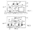
- FIGS. 1 and 2 in order to clarify the invention as a general system overview, a device designated in its entirety with 100 or 100 'is shown schematically, which device for carrying out a feed movement of a work organ (not shown in FIGS. 1 and 2) Workstation is trained.
- the feed movement of the work organ to a correspondingly assigned conveyor belt 110 (only shown in FIG. 1) or The same is done here along two coordinates in the plane which are oriented approximately at right angles to one another in the X and / or Y direction.
- the device 100 essentially comprises a base plate 10, a slide plate 15, a carrier element 20 for the working element (not shown in more detail), a first drive 25 for one oriented in the Y direction and a second drive 30 for one oriented in the X direction Infeed movement of the carrier element 20 and a guide device 50 which is operatively connected to the carrier element 20.
- the carrier element 20 is designed to receive the working element (part 45 in FIG. 4) and a boom 40.
- An optical scanning element 41 (sensor) is also provided on the arm 40 on the side facing the conveyor belt 110.
- the device 100 ' essentially comprises a base plate 10', a slide plate 15 ', a carrier element 20' with arm 40 'and scanning element 41', a first drive 25 'for the in the X direction and a second drive 30 'for the infeed movement oriented in the Y direction.
- a further third drive 31 which corresponds to the first drive 25 ', is provided in the device 100' instead of the guide device 50.
- FIG. 2 shows the measuring elements 42, 43 and 44 assigned to the drives 25 'and 30' and 31, which measuring elements are designed and arranged for a distance measurement and for a parallelism measurement and control.
- the respective carrier element 20, 20' is secured against vertical forces on the sliding plate 15, 15 'by means of a vacuum-preloadable air cushion bearing 1, which is referred to below as air bearing 1 the plane in The X and / or Y direction is freely movable.
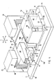
- 4 shows, as a preferred embodiment, the device 100 shown on a larger scale and in a perspective view, and the base plate 10, the slide plate 15, the support element 20 with the extension arm 40, the two drives 25 and 30 and the guide device 50 can be seen.
- the base plate 10 has an absolutely flat mounting surface 11, which is provided as a support and fastening surface for the two drives 25, 30 and for the sliding plate 15 and is designed accordingly.
- the sliding plate 15 is fastened to the base plate 10 by means not shown in detail and is provided with a flat sliding surface 16 on the side facing the carrier element 20 and the guide device 50.
- the sliding surface 16 has an appropriately designed, preferably ground surface structure.
- the base plate 10 and the slide plate 15 can also be formed in one piece while maintaining the corresponding support, fastening and sliding surfaces.
- the carrier element 20 is preferably designed as a box-shaped hollow body with a recess 46 for receiving and fastening the working member 45, for example for receiving a gripper member 45 which is designed for semiconductor technology.
- a vacuum-preloadable air bearing 1 is arranged on the underside of the carrier element 20, designated 21, for compensation of forces acting vertically on the carrier element 20.
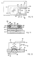
- FIG. 5 shows, in the direction of arrow V in FIG. 4, the air bearing 1 arranged on the underside 21 of the carrier element 20 and one recognizes a vacuum zone 22 designed as a depression or recess, which is completely surrounded by a compressed air zone provided with bores 23 'or the like arranged at a distance from one another 23 is surrounded.
- the guide device 50 comprises a guide part 51 and a sliding part 60.
- the guide part 51 which is U-shaped in profile cross section, has two webs 53, 54 which are arranged approximately parallel to one another and connected to one another by a flange 52.
- the guide part 51 is arranged with the two webs 53, 54 on the sliding surface 16 of the sliding plate 15 and is detachably fastened with fastening means, not shown.
- the two inner sides 53 'and 54' of the webs 53, 54 facing the sliding part 60 are designed as counter-pressure bearings 4.
- FIG. 6 shows in section along the line VI-VI in FIG. 4, as an exemplary embodiment, the guide part 51 with the counter-pressure bearing 4 arranged on one inner side 53 ', and two compressed air zones 55, which are spaced apart from one another by a recess or recess 57, can be seen , 55 ', which are provided with bores 56, 56' arranged at a distance from one another.
- the essentially cuboid-shaped sliding part 60 is provided on the one hand on the end face 61 facing the side wall 24 of the carrier element 20 with an air bearing 3 and on the other hand on the underside 65 facing the sliding surface 16 of the sliding plate 15 with an air bearing 2.
- FIG. 7 shows, in the direction of arrow VII in FIG. 4, the air bearing 2 arranged on the underside 65 of the sliding part 60 and two compressed air zones 67, 67 'arranged at a distance from one another through a recess or recess 68, in each of which one as a recess or recess trained vacuum zone 66,66 'is arranged.
- FIG. 8 shows, in the direction of arrow VIII in FIG. 4, the air bearing 3 arranged on the end face 61 of the sliding part 60 and one recognizes a vacuum zone 62 designed as a recess or depression and a compressed air zone 63, 63 'surrounding the vacuum zone 62 with bores arranged at a distance from one another 64, 64 '.
- the air bearing 1 (FIG. 5) arranged on the underside 21 of the carrier element 20 and the air bearing 2 (FIG. 7) arranged on the underside 65 of the sliding part 60 and that on the end face 61 of the sliding part 60 arranged air bearing 3 (Fig. 8) is designed as a vacuum-preloadable air bearing, while the air bearing 4 assigned to the two side surfaces 60 ', 60 "of the sliding part 60 and arranged on the inner sides 53', 54 'of the webs 53, 54 (Fig.
- the individual air bearings 1, 2, 3 and 4 are operatively connected to a corresponding energy source via a duct system, not shown and arranged in the individual elements, for generating the vacuum mentioned or for supplying compressed air.
- the two electromotive drives 25 and 30 according to FIG. 4 are identical to one another in terms of their construction and mode of operation. At this point, only the essential elements of one drive 25 are described:
- the drive 25 comprises a stator body 28 provided with magnets (not shown), a coil body 27 which is arranged in correspondingly configured slots 29 (only one slot shown) of the stator body 28 and which is arranged on a carrier member 26.
- the stator body 28 has at least two slots 29 arranged at a parallel distance from one another and is arranged on the surface 11 of the base plate 10, preferably detachably, by means not shown in detail.
- the carrier member 26 is designed to receive the bobbin 27 and detachably fastened to the carrier element 20 by means not shown in detail.
- a further support member 26 ' is provided on the support element 20 for receiving a coil body (not designated) for the drive 30.
- the individual, not designated elements of the drive 30 are with the elements 27, 28 and 29 of the drive 25 identical.
- the individual parts of the electromotive drives 25 and 30 according to FIG. 1 and FIG. 4 and the parts 25 ', 30', 31 according to FIG. 2 are designed and arranged with respect to one another in such a way that when the coil body 27 is excited by a corresponding direct current or direct current pulse a horizontal lifting movement of the parts 27, 26 and 20, which are operatively connected to one another, is produced relative to the stator body 28 in the X and / or Y direction. Due to the special design and arrangement of the parts 26 and 27 in the slots 29 of the stator body 28, in addition to the essentially linear movement in the X or Y direction, one can also be oriented approximately transversely thereto, ie, approximately parallel to the winding course of the coil body 27 Movement.
- This so-called productive transverse movement depends on the inner dimensions of the parts 26, 27, for example, in the form of a box frame, in relation to the outer dimensions of the central flange of the stator body 28, which is surrounded and completely surrounded by the parts 26, 27.
- the support member 26 for the coil body 27 is rigidly connected to the support element 20 and forms a floating structural unit that is largely freely movable in the horizontal plane relative to the fixed stator body 28.
- the support member 26 is in this case arranged on the support element 20 and fastened by means not shown in such a way that the force flow acting on the support element 20 essentially runs through the center of gravity of the support element 20.
- the support element 20 together with the coil body 27 and the support member 26 can be moved relative to the fixed stator body 28 in a first direction, which runs approximately in the same direction with the coil axis (not designated), and in a second direction, oriented approximately at right angles thereto.
- the electric motor drive 30 is configured analogously to the drive 25.
- drives also have the possibility of designing the stator body 28 and the support element 20 or 20 'as one structural unit and of designing and arranging the support member 26 with the coil body 27 in a fixed manner.
- the carrier element 20, 20 ', together with the stator body can be moved relative to a fixedly arranged carrier member for the coil body in a first direction which is approximately in the same direction as the coil axis, and in the second direction, which is oriented approximately at right angles thereto.
- FIG. 9 shows a schematically represented variant of a guide device 150 for the device 100 shown in FIG. 1, and the base plate 10 with the slide plate 15 arranged thereon and the one which is adjustable on the slide plate in the X and / or Y direction and which can be seen with the drives, not shown here, operatively connected support element 20.
- the support element 20 is likewise arranged such that it can be freely moved on the slide plate 15 by means of the vacuum preloadable air bearing 1 shown in FIG.
- the guide device 150 comprises a sliding part 160 which is T-shaped in cross section and has a flange 161 and a web 162 arranged approximately transversely thereto, which is guided with the web 162 on a guide part 151 designed in the form of a bar.
- the guide member 151 is detachably attached to the surface of the slide plate 15 by means not shown.
- the vertically oriented flange surface 161 ′ facing the carrier element 20 and the vertically oriented guide surface 151 ′ facing the web 162 are each provided with a vacuum-preloadable air bearing 3, for example shown in Fig. 8 provided.
- the guide device 250 comprises a sliding part 260 which is formed in two parts from a bar-like flange 261 and a plate-like web 262.
- the web 262 is operatively connected to the flange 261 by means of a sheet metal strip 263 which is integrated in the parts 261 and 262 and has a spring-elastic effect.
- the sliding part 260 as shown in FIG.
- a profile body is provided as a connecting element, in the example shown a cylindrical profile body 252, 252', the parts 251, 251 'and the web 262 being provided with recesses corresponding to the profile body.
- an air bearing 265, 265' is provided between the outer surface of the individual profile body 252, 252 'and the recess in the web 262 of the sliding part 260.
- the devices are on the devices for detecting the current position of the carrier element 20, 20 'and for correspondingly controlling or actuating the associated electromotive drives 25, 30 or 25', 30 ', 31 or 32, 32' 100, 100 'appropriately designed measuring elements are provided and arranged, by means of which, depending on a result, for example a comparison result, the respective drive acting in the X or Y direction is actuated, for example is actuated by a DC excitation pulse.
- two measuring elements 72, 73 are arranged in the carrier element 20, as shown schematically in FIG. 12, on the underside 21 facing the sliding plate 15 in a correspondingly designed recess 18 and detachably attached with means not shown.
- Two measuring heads 70 and 71 assigned to the measuring elements 72, 73 are arranged in a recess 17 of the sliding plate 15 and fastened by means not shown.
- the individual elements 70 to 75 together form an optronic measuring device 80.
- so-called glass scales can be provided as measuring elements 72, 73, one of which is provided with line units oriented in the X direction and the other with line units oriented in the Y direction .
- a one-piece plate or the like provided with line units oriented in the X and Y directions or the like can also be installed in the recess 18 or arranged at a suitable location on the carrier element 20.
- position-dependent data are determined from the measuring elements 72, 73 arranged on the carrier element 20 and converted into signals which correspond via lines 74, 75, for example, to the electromotive drives 25, 30 or one of the drives 25, 30 actuating control device (not shown) are supplied.
Abstract
Description
Die Erfindung betrifft eine Einrichtung zur Durchführung der Zustellbewegung eines Arbeitsorgans, insbesondere eines Bondkopfes zu einer Arbeitsstation.The invention relates to a device for carrying out the feed movement of a work organ, in particular a bond head to a work station.
Aus der DE-PS 22 44 442 ist eine im wesentlichen mit elektrischen Mitteln betätigbare Einstellvorrichtung bekannt, welche ein Ständerglied sowie ein Läuferglied umfasst. Die dem Läuferglied zugewandte Fläche des Ständerglieds ist hierbei in Bezirke aufgeteilt, von den jeder Bezirk parallel zueinander verlaufende Rippen aus magnetisierbarem Material aufweist. An der Unterseite des Läufergliedes sind mit den genannten Bezirken zusammenwirkende, elektromagnetische Mittel derart angeordnet, dass bei Erregung der elektromagnetischen Mittel eine Bewegung des Läufergliedes in X- oder Y-Richtung erfolgen kann. Zwischen dem Läuferglied und dem Ständerglied kann weiterhin ein Luftzwischenraum vorgesehen sein, so dass das als Kopfstück ausgebildete Läuferglied im wesentlichen auf einem Luftkissen über dem als Platte ausgebildeten Ständerglied schwebt.From DE-PS 22 44 442 a setting device which can be actuated essentially by electrical means is known, which comprises a stator member and a rotor member. The surface of the stator member facing the rotor member is divided into districts, each of which has ribs made of magnetizable material that run parallel to one another. On the underside of the rotor member, electromagnetic means cooperating with the named districts are arranged in such a way that when the electromagnetic means are excited, the rotor member can move in the X or Y direction. An air gap can also be provided between the rotor member and the stator member, so that the rotor member designed as a head piece essentially hovers on an air cushion above the stator member designed as a plate.
Aus der US-A 4 654 571 ist eine Einrichtung bekannt, welche im wesentlichen eine zur Aufnahme eines kreisscheibenförmigen Halbleiterelementes ausgebildete Plattform umfaßt. Die Plattform ist mittels drei im Abstand zueinander angeordneter und als Luftlager ausgebildeter Ausleger auf einer ebenen Platte gelagert. Das auf der Plattform liegende Halbleiterelement wird hierbei von einem zugeordneten Phototeil über eine Photomaske entsprechend belichtet. Die Platte ist auf der der Plattform zugewandten Seite mit weitgehend über die gesamte Fläche verteilt angeordneten, magnetischen Elementen und die Plattform auf der der Platte bzw. der magnetischen Element zugewandten Seite mit vier symmetrisch zur vertikalen Achse der Plattform angeordneten Spulenkörpern versehen. Mittels der Magnet- und Spulenelement ist bei entsprechender Erregung die Plattform in X- und Y-Richtung in der Ebene relativ zu der Platte verstellbar. Die Luftlagerung geschieht entsprechend der US-A 4 654 571 ausschliesslich durch aus einem kreuzförmigen Schlitz austretende Druckluft. Hierdurch ist jedoch keine exakte Luftlagerung möglich. Ferner kann durch eine schachbrettförmige Anordnung von Magnetelementen, welche mit entsprechenden Spulen in einem Körper zusammenwirken, niemals die Genauigkeit der Bewegung eines Arbeitselementes erreicht werden, wie dies für eine gattungsgemässe Zustellvorrichtung erforderlich ist.From US-A 4 654 571 a device is known which essentially comprises a platform designed to receive a circular disk-shaped semiconductor element. The platform is mounted on a flat plate by means of three cantilevers which are arranged at a distance from one another and are designed as air bearings. The semiconductor element lying on the platform is appropriately exposed by an assigned photo part via a photo mask. The plate is arranged on the side facing the platform with largely distributed over the entire surface, Magnetic elements and the platform on the side facing the plate or the magnetic element with four symmetrical to the vertical axis of the platform arranged bobbins. With appropriate excitation, the platform can be adjusted in the X and Y direction in the plane relative to the plate by means of the magnet and coil element. According to US Pat. No. 4,654,571, the air is stored exclusively by compressed air emerging from a cross-shaped slot. However, this does not allow exact air storage. Furthermore, a chessboard-shaped arrangement of magnetic elements, which interact with corresponding coils in a body, can never achieve the accuracy of the movement of a working element, as is required for a generic delivery device.
Aus dem Prospekt "Der Messrobot, der es mit jedem anderen aufnimmt..." der Fa. Wyler AG, Wasserwagen- und Werkzeugfabrik in Winterthur, der mit Kundenschreiben vom 29.10.84 zur Messe Microtecnic 84 kekannt wurde, geht ein Messroboter mit drei relativ zueinander bewegbaren Schlitten aus Stein hervor. Die Schlitten werden über spezielle Luftlager geführt, bei denen mittels eines Ueberdrucks in drei sich verwundenen Spiralen ein Luftkissen gebildet wird und ein umschliessender Vakuumring die Haftung übernimmt. Eine Gleitplatte ist jedoch nicht vorgesehen.From the brochure "The measuring robot that takes on everyone else ..." from Wyler AG, Wasserwagen- und Werkzeugfabrik in Winterthur, which was known to customers from October 29, 1984 at the Microtecnic 84 trade fair, a measuring robot with three is relative mutually movable sledge made of stone. The sledges are guided over special air bearings, in which an air cushion is formed by means of an overpressure in three twisted spirals and a surrounding vacuum ring assumes the liability. However, a slide plate is not provided.
Aus der EP-0 121 829-B1 ist ferner ein Lagerkörper für Luftlagerungen bekannt. Dieser Lagerkörper weist eine zentral in eine Lagerfläche mündende Luftzuführöffnung und mehrere, von der Luftzuführöffnung spiralförmig in der Lagerfläche nach aussen verlaufende, sich um einen Winkel von mehr als 360° erstreckende Luftführungskanäle auf. Dadurch wird eine gleichmässige Luftverteilung im Luftspalt zwischen den Lagerflächen des Luftlagers erreicht. Konzentrisch zur Luftzuführöffnung ist zur Stabilisierung des Lagers eine die Lagerfläche kanalförmig umschliessende, an einer Unterdruckquelle anschliessbare Luftabführungsöffnung vorgesehen.A bearing body for air bearings is also known from EP-0 121 829-B1. This bearing body has an air supply opening opening centrally into a bearing surface and a plurality of air guide channels which extend outward from the air supply opening in a spiral in the bearing surface and extend through an angle of more than 360 °. A uniform air distribution in the air gap between the bearing surfaces of the air bearing is thereby achieved. Concentric to the air supply opening is to stabilize the Bearing provided an air discharge opening enclosing the bearing surface in the form of a channel and connectable to a vacuum source.
Schliesslich beschreibt die DE-1 911 908-C eine Einrichtung zum messbaren Verschieben eines auf einem Objektträger angeordneten Objektes in zwei senkrecht zueinander stehende Richtungen, bei der die Führungsleisten des Objektträgers in unabhängig voneinander beweglichen Geradführungen gelagert sind, welche an voneinander getrennt gelagerten Schlitten angeordnet sind. Der Objektträger ist über aerostatische, auf der Grundplatte laufende Stützlager in der Messebene geführt.Finally, DE-1 911 908-C describes a device for the measurable displacement of an object arranged on a specimen slide in two mutually perpendicular directions, in which the guide strips of the specimen slide are mounted in linear guides which can be moved independently of one another and which are arranged on slides which are mounted separately from one another . The slide is guided over aerostatic support bearings running on the base plate in the measuring plane.
Eine Aufgabe der Erfindung ist darauf gerichtet, eine Einrichtung zu schaffen, die mit einfachen Mitteln eine gegen vertikal am Trägerelement wirkende Kräfte gesicherte, hochdynamische und exakte Zustellbewegung des mit einem Arbeitsorgan versehenen Trägerelements zu der Arbeitsstation ermöglicht.It is an object of the invention to provide a device which, with simple means, enables a highly dynamic and exact infeed movement of the carrier element provided with a working element to the work station, secured against vertical forces acting on the carrier element.
Erfindungsgemäss wird diese Aufgabe durch die Merkmale von Anspruch 1 gelöst.According to the invention, this object is achieved by the features of claim 1.
Ausführungsbeispiele sowie zweckmässige Ausgestaltungen ergeben sich aus der folgenden Beschreibung in Verbindung mit der Zeichnung und den einzelnen Patentansprüchen.Exemplary embodiments and expedient configurations result from the following description in conjunction with the drawing and the individual patent claims.
Die Erfindung wird nachstehend anhand der Zeichnungen beschrieben. Es zeigt:
- Fig. 1
- ein erstes, schematisch dargestelltes Ausführungsbeispiel einer Einrichtung zur Durchführung einer Zustellbewegung eines Arbeitsorgans zu einer Arbeitsstation;
- Fig. 2
- ein zweites, schematisch dargestelltes Ausführungsbeispiel der Einrichtung zur Durchführung der Zustellbewegung des Arbeitsorgans;
- Fig. 4
- die in grösserem Massstab und in perspektivischer-Ansicht dargestellte Einrichtung gemäss Fig.1,
- Fig. 5
- eine gemäss Pfeilrichtung V in Fig.4 schematisch dargestellte Unterseite eines Trägerelements für das Arbeitsorgan,
- Fig. 6
- eine im Schnitt gemäss der Linie VI-VI in Fig.4 dargestellte Führungsvorrichtung für die Einrichtung gemäss Fig.1,
- Fig. 7
- eine gemäss Pfeilrichtung VII in Fig.4 schematisch dargestellte Unteransicht eines Führungsteils für die Einrichtung gemäss Fig.1,
- Fig. 8
- eine gemäss Pfeilrichtung VIII in Fig.4 schematisch dargestellte Vorderansicht des Führungsteils für die Einrichtung gemäss Fig.1,
- Fig. 9
- eine schematisch dargestellte erste Variante der Führungsvorrichtung für die Einrichtung gemäss Fig.1,
- Fig.10
- eine schematisch dargestellte zweite Variante der Führungsvorrichtung für die Einrichtung gemäss Fig.1,
- Fig.11
- einen Schnitt gemäss der Linie XI-XI durch die Führungsvorrichtung gemäss Fig.10,
- Fig.12
- eine schematisch dargestellte Mess-Vorrichtung für die Einrichtung gemäss Fig.1 und Fig.4.
- Fig. 1
- a first, schematically illustrated embodiment of a device for performing a feed movement of a work organ to a work station;
- Fig. 2
- a second, schematically illustrated embodiment of the device for performing the feed movement of the working organ;
- Fig. 4
- the device shown on a larger scale and in perspective view according to Figure 1,
- Fig. 5
- 4 shows an underside of a carrier element for the working element, shown schematically in the direction of arrow V in FIG. 4,
- Fig. 6
- a guide device shown in section along the line VI-VI in Figure 4 for the device according to Figure 1,
- Fig. 7
- 4 shows a bottom view of a guide part for the device according to FIG. 1, shown schematically in the direction of arrow VII in FIG. 4,
- Fig. 8
- 4 shows a front view of the guide part for the device according to FIG. 1, shown schematically in the direction of arrow VIII in FIG. 4,
- Fig. 9
- 2 shows a schematically illustrated first variant of the guide device for the device according to FIG. 1,
- Fig. 10
- 2 shows a schematically illustrated second variant of the guide device for the device according to FIG. 1,
- Fig. 11
- 4 shows a section along the line XI-XI through the guide device according to FIG. 10,
- Fig. 12
- a schematically illustrated measuring device for the device according to Fig.1 and Fig.4.
In den Figuren 1 und 2 ist zur Verdeutlichung der Erfindung als allgemeine System-übersicht jeweils eine in ihrer Gesamtheit mit 100 oder 100' bezeichnete Einrichtung schematisch dargestellt, welche zur Durchführung einer Zustellbewegung eines Arbeitsorgans (in den Figuren 1 und 2 nicht dargestellt) zu einer Arbeitsstation ausgebildet ist. Die Zustellbewegung des Arbeitsorgans zu einem entsprechend zugeordneten Transportband 110 (nur in Fig.1 dargestellt) oder dergleichen erfolgt hierbei etwa längs zweier, in der Ebene etwa rechtwinklig zueinander orientierter Koordinaten in X-und/oder Y-Richtung.In FIGS. 1 and 2, in order to clarify the invention as a general system overview, a device designated in its entirety with 100 or 100 'is shown schematically, which device for carrying out a feed movement of a work organ (not shown in FIGS. 1 and 2) Workstation is trained. The feed movement of the work organ to a correspondingly assigned conveyor belt 110 (only shown in FIG. 1) or The same is done here along two coordinates in the plane which are oriented approximately at right angles to one another in the X and / or Y direction.
Die Einrichtung 100 gemäss Fig.1 umfasst im wesentlichen eine Grundplatte 10, eine Gleitplatte 15, ein Trägerelement 20 für das nicht näher dargestellte Arbeitsorgan, einen ersten Antrieb 25 für eine in Y-Richtung und einen zweiten Antrieb 30 für eine in X-Richtung orientierte Zustellbewegung des Trägerelements 20 sowie eine mit dem Trägerelement 20 in Wirkverbindung stehende Führungsvorrichtung 50. Das Trägerelement 20 ist zur Aufnahme des Arbeitsorgans (Teil 45 in Fig.4) und eines Auslegers 40 ausgebildet. An der dem Transportband 110 zugewandten Seite ist an dem Ausleger 40 weiterhin ein optisches Abtastelement 41 (Sensor) vorgesehen.The
Die Einrichtung 100' gemäss Fig.2 umfasst im wesentlichen eine Grundplatte 10', eine Gleitplatte 15', ein Trägerelement 20' mit Ausleger 40' und Abtastelement 41', einen ersten Antrieb 25' für die in X-Richtung und einen zweiten Antrieb 30' für die in Y-Richtung orientierte Zustellbewegung. Abweichend von der Einrichtung 100 gemäss Fig.1 ist bei der Einrichtung 100' anstelle der Führungsvorrichtung 50 ein weiterer, korrespondierend zu dem ersten Antrieb 25' angeordneter dritter Antrieb 31 vorgesehen. Weiterhin erkennt man in Fig.2 den Antrieben 25' und 30'sowie 31 zugeordnete Messorgane 42,43 und 44, welche Messorgane für eine Abstandsmessung sowie für eine Parallelitätsmessung und Regelung ausgebildet und entsprechend angeordnet sind.The
Bei den vorstehend beschriebenen Ausführungsbeispielen der Einrichtung 100 und 100' gemäss Figur 1 und 2 ist das jeweilige Trägerelement 20,20' mittels einem vakuumvorspannbaren Luftkissenlager 1, welches nachstehend als Luftlager 1 bezeichnet ist, gegen vertikale Kräfte gesichert an der Gleitplatte 15,15' in der Ebene in
X- und /oder Y-Richtung frei beweglich gelagert.
Fig.4 zeigt als bevorzugtes Ausführungsbeispiel die in grösserem Massstab und in perspektivischer Ansicht dargestellte Einrichtung 100 und man erkennt die Grundplatte 10, die Gleitplatte 15, das Trägerelement 20 mit dem Ausleger 40, die beiden Antriebe 25 und 30 sowie die Führungsvorrichtung 50.In the exemplary embodiments of the
The X and / or Y direction is freely movable.
4 shows, as a preferred embodiment, the
Die Grundplatte 10 hat eine absolut ebene Montagefläche 11, welche als Auflage- und Befestigungsfläche für die beiden Antriebe 25,30 sowie für die Gleitplatte 15 vorgesehen und entsprechend ausgebildet ist.The
Die Gleitplatte 15 ist mit nicht näher dargestellten Mitteln auf der Grundplatte 10 befestigt und ist auf der dem Trägerelement 20 und der Führungsvorrichtung 50 zugewandten Seite mit einer ebenen Gleitfläche 16 versehen. Die Gleitfläche 16 hat zur Bildung eines sogenannten Luftlagers eine entsprechend ausgebildete, vorzugsweise geschliffene Oberflächenstruktur. Die Grundplatte 10 sowie die Gleitplatte 15 können unter Beibehaltung der entsprechenden Auflage-, Befestigungs- und Gleitflächen auch als eine Baueinheit einstückig ausgebildet sein.The sliding
Das Trägerelement 20 ist vorzugsweise als kastenförmiger Hohlkörper mit einer Ausnehmung 46 zur Aufnahme und Befestigung des Arbeitsorgans 45, beispielsweise zur Aufnahme eines für die Halbleitertechnik entsprechend ausgebildeten Greiferorgans 45 ausgebildet. An der mit 21 bezeichneten Unterseite des Trägerelements 20 ist zur Kompensation vertikal am Trägerelement 20 wirkender Kräfte ein vakuumvorspannbares Luftlager 1 angeordnet.The
Fig.5 zeigt gemäss Pfeilrichtung V in Fig.4 das an der Unterseite 21 des Trägerelements 20 angeordnete Luftlager 1 und man erkennt eine als Vertiefung oder Ausnehmung ausgebildete Vakuumzone 22, welche vollumfänglich von einer mit im Abstand zueinander angeordneten Bohrungen 23' oder dergleichen versehenen Druckluftzone 23 umgeben ist.5 shows, in the direction of arrow V in FIG. 4, the air bearing 1 arranged on the
Die Führungsvorrichtung 50 umfasst ein Führungsteil 51 sowie ein Schiebeteil 60. Das im Profilquerschnitt U-förmig ausgebildete Führungsteil 51 hat zwei etwa parallel zueinander angeordnete und durch einen Flansch 52 miteinander verbundene Stege 53,54. Das Führungsteil 51 ist mit den beiden Stegen 53,54 auf der Gleitfläche 16 der Gleitplatte 15 angeordnet und mit nicht näher dargestellten Befestigungsmitteln lösbar befestigt. Die beiden dem Schiebeteil 60 zugewandten Innenseiten 53' und 54' der Stege 53,54 sind als Gegendrucklager 4 ausgebildet.The
Fig.6 zeigt im Schnitt gemäss der Linie VI-VI in Fig.4 als Ausführungsbeispiel das Führungsteil 51 mit dem an der einen Innenseite 53' angeordnete Gegendrucklager 4 und man erkennt zwei durch eine Vertiefung oder Ausnehmung 57 im Abstand zueinander angeordnete und getrennte Druckluftzonen 55,55', welche mit im Abstand zueinander angeordneten Bohrungen 56,56' versehen sind.6 shows in section along the line VI-VI in FIG. 4, as an exemplary embodiment, the
Das im wesentlichen quaderförmig ausgebildete Schiebeteil 60 ist einerseits auf der der Seitenwand 24 des Trägerelements 20 zugewandten Stirnseite 61 mit einem Luftlager 3 und andererseits auf der der Gleitfläche 16 der Gleitplatte 15 zugewandten Unterseite 65 mit einem Luftlager 2 versehen.The essentially cuboid-shaped sliding
Fig.7 zeigt gemäss Pfeilrichtung VII in Fig.4 das an der Unterseite 65 des Schiebeteils 60 angeordnete Luftlager 2 und man erkennt zwei durch eine Ausnehmung oder Vertiefung 68 im Abstand zueinander angeordnete Druckluftzonen 67,67', in welchen jeweils eine als Ausnehmung oder Vertiefung ausgebildete Vakuumzone 66,66' angeordnet ist. In den einzelnen Druckluftzonen 67,67' sind entsprechend im Abstand zueinander angeordnete Bohrungen 69,69' vorgesehen.7 shows, in the direction of arrow VII in FIG. 4, the
Fig.8 zeigt gemäss Pfeilrichtung VIII in Fig.4 das an der Stirnseite 61 des Schiebeteils 60 angeordnete Luftlager 3 und man erkennt eine als Ausnehmung oder Vertiefung ausgebildete Vakuumzone 62 sowie eine die Vakuumzone 62 umgebende Druckluftzone 63,63' mit im Abstand zueinander angeordneten Bohrungen 64, 64'.8 shows, in the direction of arrow VIII in FIG. 4, the air bearing 3 arranged on the
An dieser Stelle sei darauf hingewiesen, dass das an der Unterseite 21 des Trägerelements 20 angeordnete Luftlager 1 (Fig.5) und das an der Unterseite 65 des Schiebeteils 60 angeordnete Luftlager 2 (Fig.7) sowie das an der Stirnseite 61 des Schiebeteils 60 angeordnete Luftlager 3 (Fig.8) jeweils als ein vakuumvorspannbares Luftlager ausgebildet ist, während das den beiden Seitenflächen 60',60" des Schiebeteils 60 zugeordnete und an den Innenseiten 53',54' der Stege 53,54 angeordnete Luftlager 4 (Fig.6) vorzugsweise als ein sogenanntes Gegendrucklager ausgebildet ist. Die einzelnen Luft-lager 1,2,3 und 4 sind zur Erzeugung des erwähnten Vakuums oder für die Druckluftzufuhr über ein nicht näher dargestelltes und in den einzelnen Elementen angeordnetes Kanalsystem mit einer entsprechenden Energiequelle wirkverbunden.At this point, it should be pointed out that the air bearing 1 (FIG. 5) arranged on the
Die beiden elektromotorischen ausgebildeten Antriebe 25 und 30 gemäss Fig.4 sind in ihrem konstruktiven Aufbau sowie in ihrer Funktionsweise miteinander identisch. An dieser Stelle werden lediglich die wesentlichen Elemente des einen Antriebs 25 beschrieben:The two
Der Antrieb 25 umfasst einen mit Magneten (nicht dargestellt) versehenen Statorkörper 28, einen in entsprechend ausgebildeten Schlitzen 29 (nur ein Schlitz dargestellt) des Statorkörpers 28 angeordneten Spulenkörper 27, welcher an einem Trägerglied 26 angeordnet ist.The
Der Statorkörper 28 hat mindestens zwei in parallelem Abstand zueinander angeordnete Schlitze 29 und ist mit nicht näher dargestellten Mitteln an der Oberfläche 11 der Grundplatte 10 angeordnet, vorzugsweise lösbar befestigt.The
Das Trägerglied 26 ist zur Aufnahme des Spulenkörpers 27 ausgebildet und mit nicht näher dargestellten Mitteln an dem Trägerelement 20 lösbar befestigt. Zur Aufnahme eines nicht bezeichneten Spulenkörpers für den Antrieb 30 ist an dem Trägerelement 20 ein weiteres Trägerglied 26' vorgesehen. Die einzelnen, nicht näher bezeichneten Elemente des Antriebs 30 sind mit den Elementen 27,28 und 29 des Antriebs 25 identisch.The
Die einzelnen Teile der elektromotorischen Antriebe 25 und 30 gemäss Fig.1 und Fig.4 sowie die Teile 25',30',31 gemäss Fig.2 sind derart ausgebildet und zueinander angeordnet, dass bei entsprechender Gleichstrom- oder Gleichstrompuls-Erregung des Spulenkörpers 27 eine horizontale Hubbewegung der miteinander wirkverbundenen Teile 27,26 und 20 relativ zu dem Statorkörper 28 in X- und/oder Y-Richtung erzeugt wird. Aufgrund der besonderen Ausbildung und Anordnung der Teile 26 und 27 in den Schlitzen 29 des Statorkörpers 28 kann zusätzlich zu der im wesentlichen linearen Bewegung in X- oder Y-Richtung auch eine etwa quer dazu, d.h., eine etwa parallel zum Windungsverlauf des Spulenkörpers 27 orientierte Bewegung erzeugt werden. Diese sogenannte ergiebige Querbewegung ist abhängig von den Innenmassen der beispielsweise kastenrahmenartig ausgebildeten Teile 26,27 in bezug zu dem Aussenmass des, von den Teilen 26,27 vollumfänglich umgebenen, nicht näher dargestellten und bezeichneten mittleren Flansches des Statorkörpers 28.
Bei dem in Fig.4 dargestellten Ausführungsbeispiel des elektromotorischen Antriebs 25 ist das Trägerglied 26 für den Spulenkörper 27 starr mit dem Trägerelement 20 verbunden und bildet eine relativ zu dem feststehenden Statorkörper 28 in horizontaler Ebene weitgehend frei bewegliche, schwebende Baueinheit. Das Trägerglied 26 ist hierbei derart an dem Trägerelement 20 angeordnet und mit nicht dargestellten Mitteln befestigt, dass der auf das Trägerelement 20 wirkende Kraftfluss im wesentlichen durch den Schwerpunkt des Trägerelements 20 verläuft. Das Trägerelement 20 zusammen mit dem Spulenkörper 27 und dem Trägerglied 26 sind hierbei relativ zu dem feststehenden Statorkörper 28 in eine erste Richtung, welche mit der Spulenachse (nicht bezeichnet) etwa gleichsinnig verläuft, sowie in eine zweite, etwa rechtwinklig dazu orientierte Richtung bewegbar. Der elektromotorische Antrieb 30 ist analog dem Antrieb 25 ausgebildet.
Bei einer nicht dargestellten Variante der elektromotorischen Antriebe besteht jedoch auch die Möglichkeit, den Statorkörper 28 und das Trägerelement 20 oder 20' als eine Baueinheit auszubilden und das Trägerglied 26 mit dem Spulenkörper 27 feststehend auszubilden und anzuordnen. Hierbei ist das Trägerelement 20,20' zusammen mit dem Statorkörper relativ zu einem feststehend angeordneten Trägerglied für den Spulenkörper in eine die erste, mit der Spulenachse etwa gleichsinnig verlaufenden Richtung, sowie in die zweite, etwa rechtwinklig dazu orientierte Richtung bewegbar.The individual parts of the electromotive drives 25 and 30 according to FIG. 1 and FIG. 4 and the
In the embodiment of the
In a variant of the electromotive, not shown However, drives also have the possibility of designing the
An dieser Stelle sei darauf hingewiesen, dass die in den Figuren 1,2 und 4 schematisch dargestellten Antriebe 25,25' und 30,30' sowie 31 in ihrem speziellen, konstruktiven Aufbau sowie in ihrer Wirkungsweise nicht Gegenstand dieser Erfindung sind und deshalb hier nicht näher beschrieben werden.At this point it should be pointed out that the
Fig.9 zeigt eine schematisch dargestellte Variante einer Führungsvorrichtung 150 für die in Fig.1 dargestellte Einrichtung 100, und man erkennt die Grundplatte 10 mit der darauf angeordneten Gleitplatte 15 sowie das auf der Gleitplatte in X- und/oder Y-Richtung verstellbare und mit den hier nicht dargestellten Antrieben wirkverbundene Trägerelement 20. Das Trägerelement 20 ist ebenfalls mittels dem in Fig.5 dargestellten, vakuumvorspannbaren Luftlager 1 auf der Gleitplatte 15 frei beweglich verstellbar angeordnet. Die Führungsvorrichtung 150 umfasst ein mit einem Flansch 161 und einem etwa quer dazu angeordneten Steg 162 im Querschnitt T-förmig ausgebildetes Schiebeteil 160, welches mit dem Steg 162 an einem balkenartig ausgebildeten Führungsteil 151 geführt ist. Das Führungsteil 151 ist mit nicht dargestellten Mitteln an der Oberfläche der Gleitplatte 15 lösbar befestigt. Die dem Trägerelement 20 zugewandte, vertikal orientierte Flanschfläche 161' sowie die dem Steg 162 zugewandte, vertikal orientierte Führungsfläche 151' sind jeweils mit einem vakuumvorspannbaren Luftlager 3, wie beispielsweise in Fig.8 dargestellt, versehen.FIG. 9 shows a schematically represented variant of a
Fig.10 zeigt eine weitere, schematisch dargestellte Variante einer mit 250 bezeichneten Führungsvorrichtung für das Trägerelement 20 der Einrichtung 100 gemäss Fig.1, und man erkennt die Grundplatte 10, die Gleitplatte 15 sowie das gegen vertikale Kräfte mittels dem in Fig.5 dargestellten Luftlager 1 vakuumvorgespannt auf der Gleitplatte 15 verstellbare Trägerelement 20 für den hier nicht dargestellten Bondkopf. Die Führungsvorrichtung 250 umfasst ein aus einem balkenartigen Flansch 261 und einem plattenartigen Steg 262 im wesentlichen zweiteilig ausgebildetes Schiebeteil 260. Der Steg 262 ist mittels einem an den Teilen 261 und 262 integrierten und federelastisch wirkenden Blechstreifen 263 mit dem Flansch 261 wirkverbunden. Das Schiebeteil 260 ist, wie in Fig.11 im Schnitt gemäss der Linie XI-XI in Fig.10 dargestellt, in zwei seitlich auf der Gleitplatte 15 angeordneten Führungsteilen 251,251' gehalten und mit geringem Spalt 264 im Abstand zu der Gleitplatte 15 angeordnet. Die dem Trägerelement 20 zugewandte, vertikale Flanschfläche 261' ist mit einem vakuumvorspannbaren Luftlager 3, wie beispielsweise in Fig.8 dargestellt, versehen. Zwischen den beiden Führungsteilen 251,251' und dem Steg 262 ist als Verbindungselement jeweils ein Profilkörper, im dargestellten Beispiel ein zylindrischer Profilkörper 252,252' vorgesehen, wobei die Teile 251,251' sowie der Steg 262 mit entsprechend dem Profilkörper ausgebildeten Ausnehmungen versehen ist. Zwischen der Aussenfläche des einzelnen Profilkörpers 252,252' und der Ausnehmung im Steg 262 des Schiebeteiles 260 ist jeweils ein nicht näher dargestelltes Luftlager 265,265' vorgesehen.10 shows a further, schematically illustrated variant of a guide device, designated 250, for the
Zum Erfassen der momentanen Stellung des Trägerelements 20,20' und zur entsprechenden Steuerung beziehungsweise Betätigung der zugeordneten elektromotorischen Antriebe 25,30 oder 25',30',31 oder 32,32' sind an den Einrichtungen 100,100' entsprechend ausgebildete Messorgane vorgesehen und angeordnet, mittels welchen in Abhängigkeit eines Ergebnisses, beispielsweise eines Vergleichs-Ergebnisses der jeweilige in X- oder Y-Richtung wirkende Antrieb betätigt, beispielsweise von einem Gleichstrom-Erregungsimpuls betätigt wird.The devices are on the devices for detecting the current position of the
Bei dem bevorzugten Ausführungsbeispiel der Einrichtung 100 gemäss Fig.1 beziehungsweise Fig.4 sind in dem Trägerelement 20, wie in Fig.12 schematisch dargestellt, auf der der Gleitplatte 15 zugewandten Unterseite 21 in einer entsprechend ausgebildeten Ausnehmung 18 zwei Messelemente 72,73 angeordnet und mit nicht näher dargestellten Mitteln lösbar befestigt. In einer Ausnehmung 17 der Gleitplatte 15 sind zwei den Messelementen 72,73 zugeordnete Messköpfe 70 und 71 angeordnet und mit nicht dargestellten Mitteln befestigt. Die einzelnen Elemente 70 bis 75 bilden zusammen eine optronische Mess-Vorrichtung 80. Als Messelemente 72,73 können beispielsweise sogenannte Glas-Massstäbe vorgesehen sein, von welchen der eine mit in X-Richtung und der andere mit in Y-Richtung orientierten Stricheinheiten versehen ist. Als Messelement kann auch eine einstückig ausgebildete, mit in X- und Y-Richtung orientierten Stricheinheiten versehene Platte oder dergleichen in die Ausnehmung 18 eingebaut oder an geeigneter Stelle des Trägerelements 20 angeordnet werden. Mittels der vorzugsweise optronisch arbeitenden Messköpfe 70,71 werden von den am Trägerelement 20 angeordneten Messelementen 72,73 stellungsabhängige Daten ermittelt und in Signale umgewandelt, welche über Leitungen 74,75 beispielsweise den elektromotorischen Antrieben 25,30 oder aber einer die Antriebe 25,30 entsprechend betätigende Steuereinrichtung (nicht dargestellt) zugeführt werden.In the preferred exemplary embodiment of the
Claims (18)
- Device for executing the feed movement of an operating member, in particular of a bonding head constructed as a gripper, to an operating station, having a support element (20, 20') which is constructed to hold the operating member, is arranged on a sliding plate (15, 15'), is operationally connected to at least two drives (25, 30), for example to electric motor drives, and can be adjusted relative to the sliding plate (15, 15') along two coordinates, orientated approximately perpendicular to one another in the plane, in the X-direction and Y-direction, the support element (20, 20') being arranged on the sliding plate (15, 15') in a fashion essentially operationally connected to the moving part of the electric motor drive, capable of moving by means of a sliding bearing, assigned to the sliding plate (15, 15'), in a prescribed, horizontal plane with degrees of translational freedom and a degree of rotational freedom, and largely freely suspended, characterized in that the degree of rotational freedom is achieved perpendicular to the XY-plane by virtue of the fact that the movable parts of the drives and the supporting element (20, 20') can be moved transverse to the respective drive direction (X and Y, respectively) into a second direction (Y and X, respectively) running approximately at right angles, and in that at least one aircushion bearing (1) arranged on the underside (21) facing the sliding plate (15, 15') and formed from a vacuum zone (22) as well as a compressed air zone (23) surrounding the vacuum zone (22) is arranged in a vacuum-prestressed fashion on the sliding plate (15, 15').
- Device according to Claim 1, characterized in that the support element (20) is operationally connected to a first drive (25) for the movement orientated in the Y-direction, to a second drive (30) for the movement orientated in the X-direction and, on the side opposite the first drive (25), to a guide device (50, 150, 250) and to an optoelectronic measuring device (80) correspondingly assigned to the support element (20), the measuring device (80) being constructed to detect the movement, relative to the sliding plate (15) and orientated in the X-direction and/or Y-direction, of the support element (20) as well as to actuate a controller of the two drives (25, 30) (Figures 1, 12).
- Device according to Claim 1, characterized in that the support element (20') is assigned two drives (25' and 31), correspondingly arranged relative to one another, for the movement orientated in the X-direction and a drive (30') for the movement orientated in the Y-direction, and in that for the purpose of detecting these movements orientated in the X-direction and/or Y-direction and of measuring parallelism as well as of actuating a controller of the drives (25', 30' and 31) provision is made of measuring elements (42, 43, 44) which are correspondingly constructed and thereby operationally connected (Figure 2).
- Device according to Claim 2, characterized in that the guide device (50) essentially comprises a guide part (51) and a slide part (60), and in that the slide part (60) is operationally connected, on the one hand, at an end face (61) to the support element (20) by means of a vacuum-prestressed aircushion bearing (3) arranged orthogonally relative to the sliding plate (15), and on the other hand to the sliding plate (15) by means of a vacuum-prestressed aircushion bearing (2) arranged approximately parallel to the sliding plate (15) (Figure 4).
- Device according to Claim 4, characterized in that the guide part (51) has two webs (53, 54) which are arranged at a parallel spacing from one another and perpendicular to the sliding plate (15) and between which the slide part (60) is guided displaceably in the Y-direction by means of an aircushion bearing (4) constructed as a thrust bearing (Figure 4).
- Device according to Claim 5, characterized in that the guide part (51), formed from the webs (53, 54) and a flange (52) connecting the webs to one another, is constructed with a U-shaped profile cross-section and is provided on the inner sides (53', 54') of the webs (53 or 54) with the thrust bearing (4) acting against two lateral faces (60', 60") of the slide part (60) (Figure 4).
- Device according to Claim 1, 2 or 3, characterized in that the electric motor drives (25, 30, 25'; 30', 31 or 32, 32') are constructed as electric DC or pulsed DC linear drives.
- Device according to Claims 1 and 7, characterized by the use of electric motor drives (25, 30) in which the stator member (28) has an E-shaped profile cross-section - which is known per se - with flanges arranged at a spacing from one another and provided on the inner sides with magnet members, and in that the coil former (27), which can move freely in the plane between the flanges in corresponding cutouts (29) in the plane and is operationally connected to the support element (26), can be actuated, given appropriate DC excitation, in such a way that the coil former (27), which is constructed approximately in the shape of a box-type frame and embracing the middle flange, provided as a pole, can be moved together with the support element (26) in a first direction, orientated in accordance with the axis of the coil former (27), as well as in a second direction, orientated essentially transverse thereto.
- Device according to Claim 1, 2 or 3, characterized in that the element, moved by an appropriate, electric DC or pulsed DC excitation, of the electric motor drive (25, 30; 25', 30', 31 or 32, 32') is constructed with the support element (20; 20') as a unit in which the direction of the force lines of the moving drive element essentially extends through the centroid of the support element (20, 20').
- Device according to one of Claims 1, 2 or 3, characterized in thata) each drive (25, 30, 31) comprises a fixed stator member (28) which is arranged on a base plate (10) and provided with two slots (29) arranged horizontally at a parallel spacing from one another, as well as a support member (26, 26') arranged on the support element (20) and provided for holding a coil former (27) operationally connected to the stator member (28), and in thatb) given appropriate DC excitation of the coil former (27), the coil former, (27) can be moved with the support member (26, 26') relative to the stator member (28) in the first direction (X) and/or in the second direction (Y) perpendicular thereto.
- Device according to Claims 8 and 9, characterized in that the support element (20 or 20') is constructed as a rigid unit together with the support member (26 or 26') and the respective coil former.
- Device according to Claims 2 and 4 to 10, characterized by the combination of the following features:a) the support element (20) operationally connected to the electric motor drives (25, 30) is arranged in a freely movable fashion on the sliding plate (15) by means of the vacuum-prestressable aircushion bearing (1) arranged parallel to the sliding plate (15),b) the support element (20) is guided displaceably in the X-direction with one side wall (24) at the end face (61) of the slide part (60) by means of the vacuum-prestressable aircushion bearing (3) arranged orthogonal to the sliding plate (15),c) the slide part (60) is guided displaceably in the Y-direction between the two webs (53, 54) of the guide part (51) by means of the vacuum-prestressable aircushion bearing (2), arranged parallel to the sliding plate (15), as well as by means of the aircushion thrust bearing (4), andd) the optoelectronic measuring device (80), which is essentially operationally connected to the support element (20), is constructed for the purpose of detecting the movement, orientated in the X-direction and/or Y-direction, of the support element (20) as well as of actuating the controller of the corresponding drive (25, 30) (Figure 4).
- Device according to Claim 2, characterized in that the optoelectronic measuring device (80) comprisesa) at least one measuring element (72, 73) operationally connected to the support element (20) and provided with bar units orientated in the X-direction and Y-direction, andb) on the side facing the measuring element (72, 73), at least one optoelectronic measuring head (70, 71) arranged on the sliding plate (15) in a fashion fixed with respect to the measuring element (72, 73), and in thatc) the measuring head (70, 71) actuates the controller of the drives (25, 30) as a function of position with respect to the support element (20).
- Device according to Claim 13, characterized in that the plate-like measuring element (72, 73) is arranged in a cutout (18) of the support element (20) which faces the surface (16) of the sliding plate (15), and the measuring head (70, 71) is arranged in a cutout (17) of the sliding plate (15) which faces the support element (20).
- Device according to Claim 2, characterized in that the guide device (150) comprises a slide part (160) which is constructed in the shape of a T and is guided linearly on a guide part (151) firmly connected to the sliding plate (15), and which is operationally connecteda) with the flange (161) by means of the vacuum-prestressable aircushion bearing (3) to the support element (20), andb) with the web (162) by means of a vacuum-prestressable aircushion bearing (3) to the sliding plate (15) and the guide part (151) (Figure 9).
- Device according to Claim 2, characterized in that the guide device (250) comprises a slide part (260) which is constructed approximately in the shape of a T and is mounted between two guide parts (251, 251') arranged at a spacing from one another on the sliding plate (15), and whicha) is operationally connected with the flange (261) by means of the aircushion bearing (3) to the support element (20), andb) is arranged with the web (262) in a horizontal plane at a spacing (264) from the sliding plate (15) between two guide parts (251, 251') and is mounted by means of two profile member coupling elements (252, 252') arranged in correspondingly constructed cutouts,c) there being respectively provided in the cutouts in the web (262) an aircushion thrust bearing (265, 265') acting on the corresponding coupling element (252, 252').
- Device according to one of Claims 1, 2 or 3, characterized by the use of electric motor drives (25, 30 or 25', 30', 31), in the case of which use the support element (20, 20') can be moved together with the coil former (27) and the support member (26) relative to the fixedly arranged stator member (28) in a first direction, running approximately in the same sense as the coil axis, and in a second direction orientated perpendicular thereto.
- Device according to one of Claims 1, 2 or 3, characterized by the use of electric motor drives, in the case of which use the support element (20, 20') can be moved together with the corresponding stator element relative to a fixedly arranged support member for the coil former in a first direction, running approximately in the same sense as the coil axis, as well as in a second direction orientated perpendicular thereto.
Priority Applications (1)
| Application Number | Priority Date | Filing Date | Title |
|---|---|---|---|
| AT88117965T ATE102410T1 (en) | 1987-11-25 | 1988-10-28 | DEVICE FOR CARRYING OUT THE INFEED MOVEMENT OF A WORKING ORGAN TO A WORKING STATION. |
Applications Claiming Priority (2)
| Application Number | Priority Date | Filing Date | Title |
|---|---|---|---|
| CH4579/87 | 1987-11-25 | ||
| CH457987 | 1987-11-25 |
Publications (3)
| Publication Number | Publication Date |
|---|---|
| EP0317787A1 EP0317787A1 (en) | 1989-05-31 |
| EP0317787B1 EP0317787B1 (en) | 1994-03-02 |
| EP0317787B2 true EP0317787B2 (en) | 1997-05-07 |
Family
ID=4278733
Family Applications (1)
| Application Number | Title | Priority Date | Filing Date |
|---|---|---|---|
| EP88117965A Expired - Lifetime EP0317787B2 (en) | 1987-11-25 | 1988-10-28 | Device for carrying out the readying movement of a work piece towards a work station |
Country Status (6)
| Country | Link |
|---|---|
| US (1) | US5114302A (en) |
| EP (1) | EP0317787B2 (en) |
| JP (1) | JP3353085B2 (en) |
| AT (1) | ATE102410T1 (en) |
| DE (1) | DE3888102D1 (en) |
| HK (1) | HK1000178A1 (en) |
Families Citing this family (30)
| Publication number | Priority date | Publication date | Assignee | Title |
|---|---|---|---|---|
| DE4006853A1 (en) * | 1990-03-05 | 1991-09-12 | Zeiss Carl Fa | DEVICE FOR PRELOADING A GUIDED MACHINE PART |
| DE59104416D1 (en) * | 1991-02-15 | 1995-03-09 | Esec Sa | Method and device for measuring the vibration amplitude on an energy transducer. |
| US5397212A (en) * | 1992-02-21 | 1995-03-14 | Ebara Corporation | Robot with dust-free and maintenance-free actuators |
| US5637177A (en) * | 1994-12-07 | 1997-06-10 | Van Os Enterprises | Laminating apparatus having a reciprocating press roller |
| US5733096A (en) * | 1995-09-13 | 1998-03-31 | Silicon Valley Group, Inc. | Multi-stage telescoping structure |
| DE19628921C2 (en) * | 1995-10-02 | 2000-02-24 | Wiemers Karl Heinz | Machine tool with clamping device that can be clamped and positioned using magnetic forces |
| DE59700264D1 (en) * | 1996-03-02 | 1999-08-26 | Esec Sa | Process for making a molded wire connection |
| EP0871284B1 (en) * | 1997-04-11 | 2005-09-14 | Etel S.A. | X-Y Table to move loads with high precision and very high dynamic |
| CH691719A5 (en) * | 1997-04-11 | 2001-09-14 | Etel Sa | XY table for moving a load, such as a tool, in two perpendicular directions. |
| US6140815A (en) * | 1998-06-17 | 2000-10-31 | Dover Instrument Corporation | High stability spin stand platform |
| US6531867B1 (en) | 1998-06-17 | 2003-03-11 | Dover Instrument Corp. | High stability spin stand platform with air bearing micropositioning stage |
| EP1024587A3 (en) * | 1999-01-26 | 2003-11-19 | ESEC Trading SA | Elektromagnetic drive device |
| EP1098357A1 (en) * | 1999-11-02 | 2001-05-09 | Esec Sa | Bond head for a wire bonder |
| EP1098356B1 (en) * | 1999-11-02 | 2006-02-08 | Unaxis International Trading Ltd | Bonding head for a wire bonder |
| SG92747A1 (en) | 1999-11-02 | 2002-11-19 | Esec Trading Sa | Bonhead for a wire bonder |
| US6176414B1 (en) | 1999-11-08 | 2001-01-23 | Kulicke & Soffa Investments, Inc. | Linkage guided bond head |
| US6467895B1 (en) * | 2000-02-16 | 2002-10-22 | Hewlett-Packard Company | Vacuum feeder for imaging device |
| JP2002214374A (en) | 2001-01-15 | 2002-07-31 | Agilent Technologies Japan Ltd | Positioning device and positioning method |
| US20020104453A1 (en) * | 2001-02-02 | 2002-08-08 | Martin Lee | Air bearing assembly |
| KR100458201B1 (en) * | 2001-08-09 | 2004-11-26 | 대명전기주식회사 | Grip Moving Apparatus |
| JP2003085721A (en) * | 2001-09-14 | 2003-03-20 | Mitsumi Electric Co Ltd | Head feeding mechanism |
| US7038598B2 (en) * | 2002-05-29 | 2006-05-02 | Alan K. Uke | Keyboard assemblies |
| JP3987811B2 (en) * | 2003-03-20 | 2007-10-10 | 株式会社日立ハイテクノロジーズ | XY stage, head carriage and magnetic head or magnetic disk tester |
| KR20040089480A (en) * | 2003-04-14 | 2004-10-21 | 에섹 트레이딩 에스에이 | Wire bonder with a device for determining the vectorial distance between the capillary and the image recognition system and method |
| US7159751B2 (en) * | 2003-06-06 | 2007-01-09 | Esec Trading Sa | Wire bonder |
| DE102004004020A1 (en) * | 2004-01-20 | 2005-08-11 | Index-Werke Gmbh & Co. Kg Hahn & Tessky | machine tool |
| US7141969B2 (en) * | 2004-03-29 | 2006-11-28 | Guzik Technical Enterprises | X-Y spinstand platform with flexure-coupled platen |
| US7377415B2 (en) * | 2005-06-15 | 2008-05-27 | Kulicke And Soffa Industries, Inc. | Bond head link assembly for a wire bonding machine |
| CH700015B1 (en) * | 2007-04-04 | 2010-06-15 | Oerlikon Assembly Equipment Ag | Ultrasonic Transducer. |
| DE102008020622A1 (en) * | 2008-04-24 | 2009-10-29 | Krones Ag | Device and method for re-sorting piece goods compilations |
Citations (4)
| Publication number | Priority date | Publication date | Assignee | Title |
|---|---|---|---|---|
| DE2244442A1 (en) † | 1971-09-08 | 1973-03-15 | Xynetics Inc | ADJUSTMENT DEVICE FOR EFFECTING A SPECIFIC RELATIVE MOVEMENT BETWEEN TWO LINKS ALONG A FIRST AND A SECOND COORDINATE AXIS |
| DE1911908C3 (en) † | 1969-03-08 | 1980-08-28 | Dr. Johannes Heidenhain Gmbh, 8225 Traunreut | Device for measurable displacement of an object |
| US4654571A (en) † | 1985-09-16 | 1987-03-31 | Hinds Walter E | Single plane orthogonally movable drive system |
| EP0121829B1 (en) † | 1983-03-30 | 1987-05-20 | Wyler AG Wasserwaagen und Messwerkzeuge | Bearing element for a gas bearing |
Family Cites Families (8)
| Publication number | Priority date | Publication date | Assignee | Title |
|---|---|---|---|---|
| FR2032170A5 (en) * | 1969-02-20 | 1970-11-20 | Sawyer Bruce | |
| NL7402768A (en) * | 1974-02-28 | 1975-09-01 | Philips Nv | DEVICE FOR WRITING AND / OR DISPLAYING INFORMATION IN RESPECTIVE OF A ROTATING DISK REGISTRATION CARRIER. |
| FR2442537A1 (en) * | 1978-11-22 | 1980-06-20 | Rostovskij Na Donu Inst Insche | Async. linear motor with box-shaped inductors - has core shanks connected by yoke and each core carrying two polyphase additional coils generating specified magnetic fields |
| US4229136A (en) * | 1979-03-19 | 1980-10-21 | International Business Machines Corporation | Programmable air pressure counterbalance system for a manipulator |
| JPS6091021A (en) * | 1983-10-24 | 1985-05-22 | Japan Aviation Electronics Ind Ltd | Magnetic control table |
| US4716530A (en) * | 1984-05-21 | 1987-12-29 | Kabushiki Kaisha Meidensha | System for automatically controlling movement of unmanned vehicle and method therefor |
| DD240717A1 (en) * | 1985-09-06 | 1986-11-12 | Bauakademie Ddr | HYDROSTATIC TRANSLATION SLIDING BEARING |
| US4834353A (en) * | 1987-10-19 | 1989-05-30 | Anwar Chitayat | Linear motor with magnetic bearing preload |
-
1988
- 1988-10-28 AT AT88117965T patent/ATE102410T1/en not_active IP Right Cessation
- 1988-10-28 DE DE88117965T patent/DE3888102D1/en not_active Expired - Lifetime
- 1988-10-28 EP EP88117965A patent/EP0317787B2/en not_active Expired - Lifetime
- 1988-11-22 US US07/274,865 patent/US5114302A/en not_active Expired - Lifetime
- 1988-11-25 JP JP29939188A patent/JP3353085B2/en not_active Expired - Lifetime
-
1997
- 1997-09-01 HK HK97101695A patent/HK1000178A1/en not_active IP Right Cessation
Patent Citations (4)
| Publication number | Priority date | Publication date | Assignee | Title |
|---|---|---|---|---|
| DE1911908C3 (en) † | 1969-03-08 | 1980-08-28 | Dr. Johannes Heidenhain Gmbh, 8225 Traunreut | Device for measurable displacement of an object |
| DE2244442A1 (en) † | 1971-09-08 | 1973-03-15 | Xynetics Inc | ADJUSTMENT DEVICE FOR EFFECTING A SPECIFIC RELATIVE MOVEMENT BETWEEN TWO LINKS ALONG A FIRST AND A SECOND COORDINATE AXIS |
| EP0121829B1 (en) † | 1983-03-30 | 1987-05-20 | Wyler AG Wasserwaagen und Messwerkzeuge | Bearing element for a gas bearing |
| US4654571A (en) † | 1985-09-16 | 1987-03-31 | Hinds Walter E | Single plane orthogonally movable drive system |
Also Published As
| Publication number | Publication date |
|---|---|
| ATE102410T1 (en) | 1994-03-15 |
| US5114302A (en) | 1992-05-19 |
| EP0317787A1 (en) | 1989-05-31 |
| HK1000178A1 (en) | 1998-01-16 |
| DE3888102D1 (en) | 1994-04-07 |
| JPH01216734A (en) | 1989-08-30 |
| JP3353085B2 (en) | 2002-12-03 |
| EP0317787B1 (en) | 1994-03-02 |
Similar Documents
| Publication | Publication Date | Title |
|---|---|---|
| EP0317787B2 (en) | Device for carrying out the readying movement of a work piece towards a work station | |
| DE4324918C2 (en) | Single-spindle machine tool with tool change | |
| DE3037648C2 (en) | ||
| EP2972419B1 (en) | Crossmember unit for a test apparatus for printed circuit boards, and test apparatus having said crossmember unit | |
| DE102012103554B4 (en) | coordinate measuring machine | |
| DE102006056335A1 (en) | Magnetic levitation vehicle with at least one magnet system | |
| EP0252871A1 (en) | Industrial robot | |
| DE4325347A1 (en) | Three=dimensional portal-type coordinate measuring machine slide - has horizontal right-angled triangle guide rail consisting of adjacent vertical and horizontal plane surfaces, which support corresponding slide pads, and third surface inclined to vertical for bearing force-balancing third pad | |
| DE4132333A1 (en) | COORDINATE MEASURING DEVICE | |
| WO2000068123A1 (en) | Transport system | |
| WO2018007290A1 (en) | Pipetting device having a displaceable pipetting channel having enlarged suporting location spacing | |
| DE19541085C2 (en) | Processing status with planar electromagnetic two-coordinate direct drives | |
| DE69817355T2 (en) | COLLECTORS FOR AN ELECTRIC VEHICLE SUPPLIED BY A SELF-INSULATED POWER LINE | |
| EP0330831A1 (en) | Method and device to insert electronic components in metallic support strips | |
| EP3377276B1 (en) | Liquid handling device | |
| EP2065683B1 (en) | Linear bearing with integrated linear motor | |
| DE4345094C2 (en) | Form measuring machine | |
| DE102016101695A1 (en) | Positioning device with a support plate laterally displaceable and aligned via air bearings | |
| EP1177147A1 (en) | Transport system | |
| WO1998003300A1 (en) | Machine tool system | |
| DE19921048C1 (en) | Workpiece clamp table for machine for processing parts for furniture or interior fittings has air bearings, electric linear motor stators mounted on longitudinal guide(s) and cross-bearers | |
| DE102004026534A1 (en) | Semiconductor assembly equipment | |
| WO2000054930A2 (en) | Machine tool | |
| DE3841067A1 (en) | DRIVE TABLE HIGH RESONANCE AND METHOD FOR MAKING A LEVEL WORKPLACE | |
| CH678907A5 (en) | EM positioning drive for bonding head - has stator element, magnet and coil carrier with support element for bonding head |
Legal Events
| Date | Code | Title | Description |
|---|---|---|---|
| PUAI | Public reference made under article 153(3) epc to a published international application that has entered the european phase |
Free format text: ORIGINAL CODE: 0009012 |
|
| AK | Designated contracting states |
Kind code of ref document: A1 Designated state(s): AT BE CH DE FR GB IT LI NL SE |
|
| 17P | Request for examination filed |
Effective date: 19890722 |
|
| 17Q | First examination report despatched |
Effective date: 19920410 |
|
| RAP1 | Party data changed (applicant data changed or rights of an application transferred) |
Owner name: ESEC SA |
|
| GRAA | (expected) grant |
Free format text: ORIGINAL CODE: 0009210 |
|
| AK | Designated contracting states |
Kind code of ref document: B1 Designated state(s): AT BE CH DE FR GB IT LI NL SE |
|
| REF | Corresponds to: |
Ref document number: 102410 Country of ref document: AT Date of ref document: 19940315 Kind code of ref document: T |
|
| ITF | It: translation for a ep patent filed |
Owner name: BARZANO' E ZANARDO MILANO S.P.A. |
|
| REF | Corresponds to: |
Ref document number: 3888102 Country of ref document: DE Date of ref document: 19940407 |
|
| ET | Fr: translation filed | ||
| PLBI | Opposition filed |
Free format text: ORIGINAL CODE: 0009260 |
|
| GBT | Gb: translation of ep patent filed (gb section 77(6)(a)/1977) |
Effective date: 19940608 |
|
| 26 | Opposition filed |
Opponent name: FIRMA CARL ZEISS Effective date: 19940525 |
|
| NLR1 | Nl: opposition has been filed with the epo |
Opponent name: FIRMA CARL ZEISS |
|
| PGFP | Annual fee paid to national office [announced via postgrant information from national office to epo] |
Ref country code: AT Payment date: 19941012 Year of fee payment: 7 |
|
| PGFP | Annual fee paid to national office [announced via postgrant information from national office to epo] |
Ref country code: SE Payment date: 19941017 Year of fee payment: 7 |
|
| PGFP | Annual fee paid to national office [announced via postgrant information from national office to epo] |
Ref country code: NL Payment date: 19941031 Year of fee payment: 7 |
|
| PGFP | Annual fee paid to national office [announced via postgrant information from national office to epo] |
Ref country code: BE Payment date: 19941208 Year of fee payment: 7 |
|
| EAL | Se: european patent in force in sweden |
Ref document number: 88117965.9 |
|
| PG25 | Lapsed in a contracting state [announced via postgrant information from national office to epo] |
Ref country code: AT Effective date: 19951028 |
|
| PG25 | Lapsed in a contracting state [announced via postgrant information from national office to epo] |
Ref country code: SE Effective date: 19951029 |
|
| PG25 | Lapsed in a contracting state [announced via postgrant information from national office to epo] |
Ref country code: BE Effective date: 19951031 |
|
| BERE | Be: lapsed |
Owner name: S.A. ESEC Effective date: 19951031 |
|
| PG25 | Lapsed in a contracting state [announced via postgrant information from national office to epo] |
Ref country code: NL Effective date: 19960501 |
|
| PLAW | Interlocutory decision in opposition |
Free format text: ORIGINAL CODE: EPIDOS IDOP |
|
| EUG | Se: european patent has lapsed |
Ref document number: 88117965.9 |
|
| NLV4 | Nl: lapsed or anulled due to non-payment of the annual fee |
Effective date: 19960501 |
|
| PLAW | Interlocutory decision in opposition |
Free format text: ORIGINAL CODE: EPIDOS IDOP |
|
| PUAH | Patent maintained in amended form |
Free format text: ORIGINAL CODE: 0009272 |
|
| STAA | Information on the status of an ep patent application or granted ep patent |
Free format text: STATUS: PATENT MAINTAINED AS AMENDED |
|
| 27A | Patent maintained in amended form |
Effective date: 19970507 |
|
| AK | Designated contracting states |
Kind code of ref document: B2 Designated state(s): AT BE CH DE FR GB IT LI NL SE |
|
| REG | Reference to a national code |
Ref country code: CH Ref legal event code: AEN Free format text: AUFRECHTERHALTUNG DES PATENTES IN GEAENDERTER FORM |
|
| GBTA | Gb: translation of amended ep patent filed (gb section 77(6)(b)/1977) | ||
| ET3 | Fr: translation filed ** decision concerning opposition | ||
| PGFP | Annual fee paid to national office [announced via postgrant information from national office to epo] |
Ref country code: CH Payment date: 19980203 Year of fee payment: 10 |
|
| PG25 | Lapsed in a contracting state [announced via postgrant information from national office to epo] |
Ref country code: LI Free format text: LAPSE BECAUSE OF NON-PAYMENT OF DUE FEES Effective date: 19981031 Ref country code: CH Free format text: LAPSE BECAUSE OF NON-PAYMENT OF DUE FEES Effective date: 19981031 |
|
| REG | Reference to a national code |
Ref country code: CH Ref legal event code: PL |
|
| REG | Reference to a national code |
Ref country code: GB Ref legal event code: 732E |
|
| REG | Reference to a national code |
Ref country code: FR Ref legal event code: TP |
|
| REG | Reference to a national code |
Ref country code: GB Ref legal event code: IF02 |
|
| PGFP | Annual fee paid to national office [announced via postgrant information from national office to epo] |
Ref country code: GB Payment date: 20020924 Year of fee payment: 15 |
|
| PGFP | Annual fee paid to national office [announced via postgrant information from national office to epo] |
Ref country code: FR Payment date: 20021017 Year of fee payment: 15 |
|
| PG25 | Lapsed in a contracting state [announced via postgrant information from national office to epo] |
Ref country code: GB Free format text: LAPSE BECAUSE OF NON-PAYMENT OF DUE FEES Effective date: 20031028 |
|
| GBPC | Gb: european patent ceased through non-payment of renewal fee |
Effective date: 20031028 |
|
| PG25 | Lapsed in a contracting state [announced via postgrant information from national office to epo] |
Ref country code: FR Free format text: LAPSE BECAUSE OF NON-PAYMENT OF DUE FEES Effective date: 20040630 |
|
| REG | Reference to a national code |
Ref country code: FR Ref legal event code: ST |
|
| PG25 | Lapsed in a contracting state [announced via postgrant information from national office to epo] |
Ref country code: IT Free format text: LAPSE BECAUSE OF NON-PAYMENT OF DUE FEES;WARNING: LAPSES OF ITALIAN PATENTS WITH EFFECTIVE DATE BEFORE 2007 MAY HAVE OCCURRED AT ANY TIME BEFORE 2007. THE CORRECT EFFECTIVE DATE MAY BE DIFFERENT FROM THE ONE RECORDED. Effective date: 20051028 |
|
| PGFP | Annual fee paid to national office [announced via postgrant information from national office to epo] |
Ref country code: DE Payment date: 20071030 Year of fee payment: 20 |