EP0318631A2 - Extrusion press - Google Patents
Extrusion press Download PDFInfo
- Publication number
- EP0318631A2 EP0318631A2 EP88103150A EP88103150A EP0318631A2 EP 0318631 A2 EP0318631 A2 EP 0318631A2 EP 88103150 A EP88103150 A EP 88103150A EP 88103150 A EP88103150 A EP 88103150A EP 0318631 A2 EP0318631 A2 EP 0318631A2
- Authority
- EP
- European Patent Office
- Prior art keywords
- container
- chambers
- extrusion
- press
- billet
- Prior art date
- Legal status (The legal status is an assumption and is not a legal conclusion. Google has not performed a legal analysis and makes no representation as to the accuracy of the status listed.)
- Granted
Links
Images


Classifications
-
- B—PERFORMING OPERATIONS; TRANSPORTING
- B21—MECHANICAL METAL-WORKING WITHOUT ESSENTIALLY REMOVING MATERIAL; PUNCHING METAL
- B21C—MANUFACTURE OF METAL SHEETS, WIRE, RODS, TUBES OR PROFILES, OTHERWISE THAN BY ROLLING; AUXILIARY OPERATIONS USED IN CONNECTION WITH METAL-WORKING WITHOUT ESSENTIALLY REMOVING MATERIAL
- B21C35/00—Removing work or waste from extruding presses; Drawing-off extruded work; Cleaning dies, ducts, containers, or mandrels
- B21C35/04—Cutting-off or removing waste
-
- B—PERFORMING OPERATIONS; TRANSPORTING
- B21—MECHANICAL METAL-WORKING WITHOUT ESSENTIALLY REMOVING MATERIAL; PUNCHING METAL
- B21C—MANUFACTURE OF METAL SHEETS, WIRE, RODS, TUBES OR PROFILES, OTHERWISE THAN BY ROLLING; AUXILIARY OPERATIONS USED IN CONNECTION WITH METAL-WORKING WITHOUT ESSENTIALLY REMOVING MATERIAL
- B21C23/00—Extruding metal; Impact extrusion
- B21C23/21—Presses specially adapted for extruding metal
- B21C23/212—Details
- B21C23/214—Devices for changing die or container
-
- B—PERFORMING OPERATIONS; TRANSPORTING
- B21—MECHANICAL METAL-WORKING WITHOUT ESSENTIALLY REMOVING MATERIAL; PUNCHING METAL
- B21C—MANUFACTURE OF METAL SHEETS, WIRE, RODS, TUBES OR PROFILES, OTHERWISE THAN BY ROLLING; AUXILIARY OPERATIONS USED IN CONNECTION WITH METAL-WORKING WITHOUT ESSENTIALLY REMOVING MATERIAL
- B21C27/00—Containers for metal to be extruded
-
- B—PERFORMING OPERATIONS; TRANSPORTING
- B21—MECHANICAL METAL-WORKING WITHOUT ESSENTIALLY REMOVING MATERIAL; PUNCHING METAL
- B21C—MANUFACTURE OF METAL SHEETS, WIRE, RODS, TUBES OR PROFILES, OTHERWISE THAN BY ROLLING; AUXILIARY OPERATIONS USED IN CONNECTION WITH METAL-WORKING WITHOUT ESSENTIALLY REMOVING MATERIAL
- B21C33/00—Feeding extrusion presses with metal to be extruded ; Loading the dummy block
Definitions
- This invention concerns improvements to extrusion presses and also the extrusion presses which employ such improvements and are therefore thus improved.
- the invention can be applied either to direct extrusion presses or indirect extrusion presses.
- Extrusion means here the plastic deformation of a metallic billet passed through an appropriate die, the extrusion being carried out by a ram or by the die, depending on the type of extrusion.
- Direct extrusion presses are known and are those in which the metal deformed by the thrust of a ram while passing through a die emerges in the direction of forward movement of the ram.
- Indirect extrusion presses are also known and are those in which the metal emerges in the opposite direction to the forward movement of the die.
- the withdrawal of the ram has to be such as will enable the new billet to be moved crosswise onto the axis of the extrusion chamber.
- the invention tends to eliminate the downtimes cited above and to obtain limited times for changing the billet and shearing its heel, thus enabling a high rate of output to be achieved.
- the container can move sideways and comprises at least two containment chambers having their axes parallel; a shears is provided which is suitable to shear any remaining heel of a billet in the direction of sideways movement of the container.
- the productive working cycle is substantially exactly the same as with traditional presses.
- the third chamber downstream of the extrusion position is employed for cleaning work, so that in the next position of introduction of a billet the containment chamber has already been cleaned and is ready to accept the billet.
- the shears in cooperation with the die performs th shearing of the heel, which is free to drop independently.
- the shears may have two blades, one of which can work in one direction while the other can work in the other direction, the shears forming one single body together with the container of the chambers.
- the container body comprising the chambers withdraws and a shears cooperates with the die in shearing the heel of the billet.
- the invention is therefore obtained with improvements to extrusion presses, whether the presses perform direct or indirect extrusion, according to the characterization of the main claim or of one or another of the derived claims.
- the invention is also embodied with extrusion presses, whether they perform direct or indirect extrusion, which employ the improvements cited above.
- Figs.1 and 2 and the other figures show the extrusion of solid sections, but are applicable correctly to complex and/or bored sections as well.
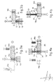
- Fig.1 gives the various steps performed by an extrusion press with a direct cycle.
- the first step 1a provides for introduction of a billet 11 into a chamber 19 after a considerable axial withdrawal of a ram 12 so as to leave the necessary space for the sideways approach of the billet 11 to take up a position along the axis of the chamber 19.
- the ram 12 When the billet 11 has been inserted into the chamber 19 of a container 10 (Fig.1b), the ram 12 is advanced and starts exerting its thrust, so that the material begins being extruded through a die 14, after which the ram 12 withdraws to let air out and then starts the actual extrusion step.
- the shears 15 performs the shearing of the heel 17 after the ram 12 and container 10 or base 13 (Fig.1d) have been distanced from the heel.
- the heel 17 has to be sheared (Fig.2c) by an appropriate shears 15, which sunders it from the extruded product 16 after the die 14 has been moved away.
- the invention eliminates these downtimes by providing an improved container 20 which can move at last sideways and possibly axially as well.
- Such container 20 (Figs.3 and 4) provides at least two chambers 19a and 19b respectively in which a billet 11 is lodged correctly.
- the container 20 may include three or more chambers 19 and be able to rotate step by step about an axis of rotation 21.
- each position of the chamber 19 will comprise its own specialized equipment directly correlated with its momentary working function.
- the second chamber 19b is free for cleaning and readying and for introduction of the next billet 11, the operation of introduction of such billet 11 being assisted by a charging means 29.
- the container 20 comprises three chambers 19 arranged, for instance, circumferentially about the axis of rotation 21, the third chamber 19c undergoes a cleaning and readying operation performed, for instance, by a cleaning means 30 while the other chambers 19a and 19b respectively performing the extrusion and charging carry out the specific tasks described.
- a charging means 29 may include a traversing carriage 35 positioned by a rapid displacement jack 36, on which is fitted a charging jack 34 that thrusts the billet 11 into the chamber 19 in its position 19b.
- the cleaning means 30 comprises a cleaning tool 33, which may also be capable of rotary movement and be actuated axially by a cleaning jack 32 that cooperates with the axis of the chamber 19 in its position 19c.
- the cleaning means 30 may act in the opposite direction to the direction of extrusion.
- the charging means 29 too may work in the same direction as, or in the opposite direction to, the direction of extrusion.
- the invention arranges that during the extrusion step at least two clamping jacks 34 actuate clamping wedges 23 with recessed brake shoes that act very close to the periphery of the chamber 19.
- the inclusion of the wedges 23 and the action of the clamping jacks 24 enable the clamping action to be restored continuously and to be kept very near to the periphery of the billet being extruded.
- the chambers 19 may comprise circumferential heated chambers 28 which serve to keep the chambers 19 at the required temperture. These heated chambers 28 may be heated with resistors which, in the case of a container 20 able to rotate in one single direction 40, are fed by a ring-type distributor.
- the container 20 passes from a working position 37 to a transfer position 38 and is removed from the die 14 by a required distance.
- the blades 15, which in the case shown are suitable to work in both directions of movement of the container 20 and protrude from the container at least momentarily, namely at least during the displacement and shearing step, pass in the neighbourhood of the die 14 and shear the heel 17.
- a variant provides for the container 20 to be able to move only in a transverse direction, whereas the die 14 withdraws axially by a distance such as will enable the blades 15 passing by to shear the heel 17 at its base.
- the cycle is substantially the same whether the extrusion is direct (Figs.3a-3b) or indirect (Figs.4a-4b).
- the only non-operational displacements are therefore a minimum reciprocal distancing of the container 20 and die 14 to enable the heel 17 to emerge fully from the chamber 19a and a sideways or rotary displacement of the container 20.
- the container 20 is displaced axially by a displacement jack 18.
- the shears 15 advances and shears the heel 17 protruding from the die 14.
- a means 31 to discharge the heel 17 may be included in cooperation with the shears 15.
- Rotation of the container 20 is obtained by the action of a motor 25, which acts by means of a pinion 26 on a gear wheel 27 coaxial with the axis of rotation 21 and solidly fixed to the container 20.
- the die 14 is held by a die holder 41, which is capable of being moved by a die-change jack 22 to make possible an easy replacement of the die 14.
- the working times required for replacements and repairs are very short and, whether the extrusion is direct or indirect, enable the efficiency of the working cycles pr unit of time to be increased considerably.
Abstract
Description
- This invention concerns improvements to extrusion presses and also the extrusion presses which employ such improvements and are therefore thus improved.
- To be more exact, the invention can be applied either to direct extrusion presses or indirect extrusion presses.
- Extrusion means here the plastic deformation of a metallic billet passed through an appropriate die, the extrusion being carried out by a ram or by the die, depending on the type of extrusion.
- Direct extrusion presses are known and are those in which the metal deformed by the thrust of a ram while passing through a die emerges in the direction of forward movement of the ram.
- Indirect extrusion presses are also known and are those in which the metal emerges in the opposite direction to the forward movement of the die.
- In the known systems of direct (Fig. 1) and indirect (Fig. 2) extrusion shown diagrammatically in the figures cited above and attached hereto for the purposes of clarification, it is necessary to arrange thereafter not only for an express and specific step of shearing the heel of the billet (Figs.1d and 3c) but also for a specific step of withdrawing the ram (Figs.1a and 2a) so as to enable a new billet to be introduced for extrusion.
- The withdrawal of the ram has to be such as will enable the new billet to be moved crosswise onto the axis of the extrusion chamber.
- The operations of shearing the heel of the previous billet, withdrawing the ram and introducing the new billet entail additional, considerable, non-productive times due to the stoppage and therefore a heavy operating cost.
- Moreover, as the ram itself has to position the billet first and then to extrude it in the state of the art, it is necessary, after the step of positioning and beginning to extrude the billet, to halt the thrust action momentarily, withdraw the ram to let out the air and then to restart the extrusion.
- This operation too is necessary in the state of the art and entails not indifferent downtimes and waste.
- The invention tends to eliminate the downtimes cited above and to obtain limited times for changing the billet and shearing its heel, thus enabling a high rate of output to be achieved.
- According to the invention the container can move sideways and comprises at least two containment chambers having their axes parallel; a shears is provided which is suitable to shear any remaining heel of a billet in the direction of sideways movement of the container. The productive working cycle is substantially exactly the same as with traditional presses.
- According to the present invention, however, while one chamber is undergoing the extrusion step, the other chamber is being cleaned, readied and charged with the next billet.
- Moreover, as the latter chamber is charged separately, the problem of withdrawal of the ram for expulsion of air does not arise.
- In a variant, in which three chambers are provided at equal distances apart on a circumference and can rotate on the axis of that circumference, the third chamber downstream of the extrusion position is employed for cleaning work, so that in the next position of introduction of a billet the containment chamber has already been cleaned and is ready to accept the billet.
- According to the invention, while the chamber is being moved from one position to another, the shears in cooperation with the die performs th shearing of the heel, which is free to drop independently.
- If the container comprises only two chambers and is therefore capable of a sideways to-and-fro movement, the shears may have two blades, one of which can work in one direction while the other can work in the other direction, the shears forming one single body together with the container of the chambers.
- According to a variant, while the chambers are being transferred from one working position to another, the container body comprising the chambers withdraws and a shears cooperates with the die in shearing the heel of the billet.
- The invention is therefore obtained with improvements to extrusion presses, whether the presses perform direct or indirect extrusion, according to the characterization of the main claim or of one or another of the derived claims.
- The invention is also embodied with extrusion presses, whether they perform direct or indirect extrusion, which employ the improvements cited above.
- The attached figures, which are given as a non-restrictive example, show the following:-
- Figs.1 and 2 give diagrams of the various working steps of the state of the art;
- Figs.3 and 4 show the art as innovated with the improvements according to the invention;
- Figs.5 to 9 show a variant of the invention.
- Figs.1 to 4 give rough diagrams since the practical application to individual extrusion presses is a design problem.
- For the sake of simplicity, Figs.1 and 2 and the other figures show the extrusion of solid sections, but are applicable correctly to complex and/or bored sections as well.
- Fig.1 gives the various steps performed by an extrusion press with a direct cycle. The first step 1a provides for introduction of a
billet 11 into achamber 19 after a considerable axial withdrawal of aram 12 so as to leave the necessary space for the sideways approach of thebillet 11 to take up a position along the axis of thechamber 19. - When the
billet 11 has been inserted into thechamber 19 of a container 10 (Fig.1b), theram 12 is advanced and starts exerting its thrust, so that the material begins being extruded through adie 14, after which theram 12 withdraws to let air out and then starts the actual extrusion step. - When the
ram 12 has ended its travel (Fig.1c), aheel 17 of the billet forms within thecontainer 10 and, to be eliminated, has to be shared from theextruded product 16 by ashears 15. - The
shears 15 performs the shearing of theheel 17 after theram 12 andcontainer 10 or base 13 (Fig.1d) have been distanced from the heel. - Instead, in the event of indirect extrusion (Fig.2) the procedure is substantially analogous since the
ram 12 has to withdraw considerably (Fig.2a) to enable thebillet 11 to be introduced into thechamber 19. - When the extrusion operations shown in Figs.2b have been carried out, a bond is formed between the
extruded product 16 and itsheel 17, which is produced in this case too. - The
heel 17 has to be sheared (Fig.2c) by anappropriate shears 15, which sunders it from theextruded product 16 after the die 14 has been moved away. - After this operation the
chamber 19 has to be cleaned and readied, and then anew billet 11 is inserted therein. - As can also be seen just from the diagrams used to show the working cycle of the direct or indirect extrusion presses, the state of the art entails long downtimes due to the shearing (positions 1d and 2c), to the introduction of the billet (positions 1a and 2a) and to the auxiliary operations and also involves an initial waste of time.
- As we said earlier, such waste of time is considerable in view of the slow movement of the ram, which cannot be displaced quickly and therefore causes very long times for its withdrawal and approach. These times are not reduced by the inclusion of traditional means to charge the billets.
- The invention eliminates these downtimes by providing an improved
container 20 which can move at last sideways and possibly axially as well. Such container 20 (Figs.3 and 4) provides at least twochambers billet 11 is lodged correctly. - According to a variant the
container 20 may include three ormore chambers 19 and be able to rotate step by step about an axis ofrotation 21. - In such a case each position of the
chamber 19 will comprise its own specialized equipment directly correlated with its momentary working function. - According to the invention, while the
first chamber 19a is in its working phase, that is to say, while thebillet 11 held in thechamber 19a is thrust by theram 12 and the material is extruded along theextrusion axis 39 through thedie 14, thesecond chamber 19b is free for cleaning and readying and for introduction of thenext billet 11, the operation of introduction ofsuch billet 11 being assisted by acharging means 29. - If the
container 20 comprises threechambers 19 arranged, for instance, circumferentially about the axis ofrotation 21, thethird chamber 19c undergoes a cleaning and readying operation performed, for instance, by a cleaning means 30 while theother chambers - In this way a plant to accompany the press is obtained in which the whole cycle can be automated and the operator's task becomes an auxiliary control function.
- A charging means 29 may include a traversing
carriage 35 positioned by arapid displacement jack 36, on which is fitted acharging jack 34 that thrusts thebillet 11 into thechamber 19 in itsposition 19b. - The cleaning means 30 comprises a
cleaning tool 33, which may also be capable of rotary movement and be actuated axially by acleaning jack 32 that cooperates with the axis of thechamber 19 in itsposition 19c. The cleaning means 30 may act in the opposite direction to the direction of extrusion. - The charging means 29 too may work in the same direction as, or in the opposite direction to, the direction of extrusion.
- The invention arranges that during the extrusion step at least two
clamping jacks 34 actuateclamping wedges 23 with recessed brake shoes that act very close to the periphery of thechamber 19. The inclusion of thewedges 23 and the action of theclamping jacks 24 enable the clamping action to be restored continuously and to be kept very near to the periphery of the billet being extruded. - This arrangement, which becomes possible owing to the special nature of the invention, enables lateral extrusions, which take place in the state of the art owing to the bending of the stiffening arms, to be avoided.
- The
chambers 19 may comprise circumferentialheated chambers 28 which serve to keep thechambers 19 at the required temperture. Theseheated chambers 28 may be heated with resistors which, in the case of acontainer 20 able to rotate in onesingle direction 40, are fed by a ring-type distributor. - When the extrusion step in the
first chamber 19a has been carried out, thecontainer 20 passes from aworking position 37 to atransfer position 38 and is removed from thedie 14 by a required distance. - In the situation of Figs.3 and 4 the
blades 15, which in the case shown are suitable to work in both directions of movement of thecontainer 20 and protrude from the container at least momentarily, namely at least during the displacement and shearing step, pass in the neighbourhood of the die 14 and shear theheel 17. - This enables the
extruded product 16 to be discharged directly by extrusion of thenext billet 11 already positioned in thechamber 19b. - A variant provides for the
container 20 to be able to move only in a transverse direction, whereas thedie 14 withdraws axially by a distance such as will enable theblades 15 passing by to shear theheel 17 at its base. - The cycle is substantially the same whether the extrusion is direct (Figs.3a-3b) or indirect (Figs.4a-4b).
- According to the invention the only non-operational displacements are therefore a minimum reciprocal distancing of the
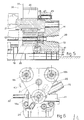
container 20 and die 14 to enable theheel 17 to emerge fully from thechamber 19a and a sideways or rotary displacement of thecontainer 20. - In the embodiment of the variant shown in Figs.5 to 9 the
container 20 is displaced axially by adisplacement jack 18. - When the container is in the
transfer position 38, theshears 15 advances and shears theheel 17 protruding from the die 14. - A
means 31 to discharge theheel 17 may be included in cooperation with theshears 15. - Rotation of the
container 20 is obtained by the action of amotor 25, which acts by means of apinion 26 on agear wheel 27 coaxial with the axis ofrotation 21 and solidly fixed to thecontainer 20. - The
die 14 is held by adie holder 41, which is capable of being moved by a die-change jack 22 to make possible an easy replacement of thedie 14. - According to the invention, therefore, the working times required for replacements and repairs are very short and, whether the extrusion is direct or indirect, enable the efficiency of the working cycles pr unit of time to be increased considerably.
Claims (10)
Priority Applications (1)
| Application Number | Priority Date | Filing Date | Title |
|---|---|---|---|
| AT88103150T ATE85914T1 (en) | 1987-12-02 | 1988-03-02 | EXTRUSION. |
Applications Claiming Priority (2)
| Application Number | Priority Date | Filing Date | Title |
|---|---|---|---|
| IT8783505A IT1230658B (en) | 1987-12-02 | 1987-12-02 | EXTRUSION PRESS. |
| IT8350587 | 1987-12-02 |
Publications (3)
| Publication Number | Publication Date |
|---|---|
| EP0318631A2 true EP0318631A2 (en) | 1989-06-07 |
| EP0318631A3 EP0318631A3 (en) | 1989-10-18 |
| EP0318631B1 EP0318631B1 (en) | 1993-02-24 |
Family
ID=11322684
Family Applications (1)
| Application Number | Title | Priority Date | Filing Date |
|---|---|---|---|
| EP88103150A Revoked EP0318631B1 (en) | 1987-12-02 | 1988-03-02 | Extrusion press |
Country Status (7)
| Country | Link |
|---|---|
| US (1) | US4895506A (en) |
| EP (1) | EP0318631B1 (en) |
| JP (1) | JPH01205812A (en) |
| AT (1) | ATE85914T1 (en) |
| DE (1) | DE3878657T2 (en) |
| ES (1) | ES2038225T3 (en) |
| IT (1) | IT1230658B (en) |
Cited By (2)
| Publication number | Priority date | Publication date | Assignee | Title |
|---|---|---|---|---|
| DE4128677A1 (en) * | 1991-08-29 | 1993-03-11 | Hasenclever Maschf Sms | Lying metal extrusion press |
| ITMI20081932A1 (en) * | 2008-11-03 | 2010-05-04 | Danieli Off Mecc | MULTIFUNCTION PRESS FOR EXTRUSION WITH MULTIPLE EQUIPMENT AND RELATIVE EXTRUSION PROCEDURE |
Families Citing this family (3)
| Publication number | Priority date | Publication date | Assignee | Title |
|---|---|---|---|---|
| IT1235395B (en) * | 1989-07-19 | 1992-06-30 | Danieli Off Mecc | HEATER OF THE HEAD OF ALUMINUM TABS TO BE EXTRUDED. |
| DE4244261C2 (en) * | 1992-12-22 | 1995-05-11 | Mannesmann Ag | Working procedure for loading a press block and metal extrusion press for carrying out the working procedure |
| IT1391753B1 (en) * | 2008-11-03 | 2012-01-27 | Danieli Off Mecc | APPARATUS AND PROCEDURE OF CONTROL OF THE MOVEMENT OF THE CONTAINER IN A PRESS BY EXTRUSION |
Citations (7)
| Publication number | Priority date | Publication date | Assignee | Title |
|---|---|---|---|---|
| DE542045C (en) * | 1926-12-09 | 1932-01-19 | Kreidler Dipl Ing Alfred | Extrusion press for cold or hot pressing of bars, tubes, strips, profiles, etc. |
| DE560116C (en) * | 1929-12-01 | 1932-09-28 | Hydraulik G M B H | Metal extruder |
| US3025959A (en) * | 1959-11-02 | 1962-03-20 | Poleschuk Stephen | Extrusion press |
| US3182478A (en) * | 1962-07-09 | 1965-05-11 | Kobe Steel Ltd | Hydraulic metal extruding machine |
| US3240046A (en) * | 1960-01-22 | 1966-03-15 | Loewy Eng Co Ltd | Metal extrusion press with multiple container system |
| US3896652A (en) * | 1974-09-11 | 1975-07-29 | Schloemann Siemag Ag | Locking system for a rotary die carrier of an extrusion |
| WO1987005238A1 (en) * | 1986-03-05 | 1987-09-11 | Stewart Charles L | Indirect extrusion process and machinery therefor |
Family Cites Families (13)
| Publication number | Priority date | Publication date | Assignee | Title |
|---|---|---|---|---|
| US2364566A (en) * | 1942-09-05 | 1944-12-05 | Stupakoff Ceramic & Mfg Compan | Extruding press |
| US3500541A (en) * | 1968-02-28 | 1970-03-17 | Albert W Hammerlund Jr | Butter patty forming device |
| US3898831A (en) * | 1974-02-06 | 1975-08-12 | Loomis Products Company | Extrusion apparatus |
| US3897184A (en) * | 1974-03-07 | 1975-07-29 | Amsted Ind Inc | Apparatus for making bars from powered metal |
| US4083666A (en) * | 1976-09-29 | 1978-04-11 | Richardson Walker L | Cookie press |
| DE2704832C2 (en) * | 1977-02-05 | 1979-03-29 | Werner & Pfleiderer, 7000 Stuttgart | Piston extruder for pressing out plastic masses |
| JPS5443073Y2 (en) * | 1977-10-19 | 1979-12-13 | ||
| GB2140342A (en) * | 1983-05-23 | 1984-11-28 | Barwell Machine & Rubber Group | Ram extruders |
| DE3424257C2 (en) * | 1984-06-30 | 1986-05-15 | Hermann Berstorff Maschinenbau Gmbh, 3000 Hannover | Equipment for the production of treads for car tires or other profiles or tracks |
| JPH0118336Y2 (en) * | 1984-10-18 | 1989-05-29 | ||
| US4731006A (en) * | 1985-08-06 | 1988-03-15 | C&F Packing Co., Inc. | Apparatus for processing food products |
| US4626189A (en) * | 1985-11-18 | 1986-12-02 | Floyd V. Hammer | Method and machine for forming articles from a plastic material |
| US4737092A (en) * | 1987-04-27 | 1988-04-12 | Dale W. Turman | Automatic dough cutter |
-
1987
- 1987-12-02 IT IT8783505A patent/IT1230658B/en active
-
1988
- 1988-03-02 EP EP88103150A patent/EP0318631B1/en not_active Revoked
- 1988-03-02 ES ES198888103150T patent/ES2038225T3/en not_active Expired - Lifetime
- 1988-03-02 DE DE8888103150T patent/DE3878657T2/en not_active Revoked
- 1988-03-02 AT AT88103150T patent/ATE85914T1/en not_active IP Right Cessation
- 1988-03-03 US US07/168,884 patent/US4895506A/en not_active Expired - Lifetime
- 1988-12-02 JP JP63304290A patent/JPH01205812A/en active Pending
Patent Citations (7)
| Publication number | Priority date | Publication date | Assignee | Title |
|---|---|---|---|---|
| DE542045C (en) * | 1926-12-09 | 1932-01-19 | Kreidler Dipl Ing Alfred | Extrusion press for cold or hot pressing of bars, tubes, strips, profiles, etc. |
| DE560116C (en) * | 1929-12-01 | 1932-09-28 | Hydraulik G M B H | Metal extruder |
| US3025959A (en) * | 1959-11-02 | 1962-03-20 | Poleschuk Stephen | Extrusion press |
| US3240046A (en) * | 1960-01-22 | 1966-03-15 | Loewy Eng Co Ltd | Metal extrusion press with multiple container system |
| US3182478A (en) * | 1962-07-09 | 1965-05-11 | Kobe Steel Ltd | Hydraulic metal extruding machine |
| US3896652A (en) * | 1974-09-11 | 1975-07-29 | Schloemann Siemag Ag | Locking system for a rotary die carrier of an extrusion |
| WO1987005238A1 (en) * | 1986-03-05 | 1987-09-11 | Stewart Charles L | Indirect extrusion process and machinery therefor |
Cited By (5)
| Publication number | Priority date | Publication date | Assignee | Title |
|---|---|---|---|---|
| DE4128677A1 (en) * | 1991-08-29 | 1993-03-11 | Hasenclever Maschf Sms | Lying metal extrusion press |
| US5301531A (en) * | 1991-08-29 | 1994-04-12 | Sms Hasenclever Gmbh | Horizontal metal extrusion press |
| ITMI20081932A1 (en) * | 2008-11-03 | 2010-05-04 | Danieli Off Mecc | MULTIFUNCTION PRESS FOR EXTRUSION WITH MULTIPLE EQUIPMENT AND RELATIVE EXTRUSION PROCEDURE |
| WO2010060753A1 (en) | 2008-11-03 | 2010-06-03 | Danieli & C. Officine Meccaniche S.P.A. | Multifunctional extruding press with multiple equipment and extrusion method thereof |
| US8613212B2 (en) | 2008-11-03 | 2013-12-24 | Danieli & C. Officine Meccaniche S.P.A. | Multifunctional extruding press with multiple equipment and extrusion method thereof |
Also Published As
| Publication number | Publication date |
|---|---|
| IT1230658B (en) | 1991-10-29 |
| DE3878657D1 (en) | 1993-04-01 |
| IT8783505A0 (en) | 1987-12-02 |
| EP0318631B1 (en) | 1993-02-24 |
| ATE85914T1 (en) | 1993-03-15 |
| DE3878657T2 (en) | 1993-06-09 |
| EP0318631A3 (en) | 1989-10-18 |
| JPH01205812A (en) | 1989-08-18 |
| ES2038225T3 (en) | 1993-07-16 |
| US4895506A (en) | 1990-01-23 |
Similar Documents
| Publication | Publication Date | Title |
|---|---|---|
| US4379398A (en) | Pull-back type indirect extrusion press | |
| EP0318631A2 (en) | Extrusion press | |
| US3025959A (en) | Extrusion press | |
| RU2076007C1 (en) | Method of making articles by backward extrusion and apparatus for performing the same | |
| US3182478A (en) | Hydraulic metal extruding machine | |
| US3240046A (en) | Metal extrusion press with multiple container system | |
| EP0539906B1 (en) | Rapid loading short-stroke extrusion press, and process | |
| US3156359A (en) | Metal extrusion press with rotary container | |
| US3147863A (en) | Extrusion press with rotary die carrier | |
| US3581545A (en) | Metal extrusion press of turntable type | |
| US3228226A (en) | Multi-container extrusion press | |
| US3364719A (en) | Metal extrusion press | |
| US2914171A (en) | Extrusion press | |
| US3359770A (en) | Method and apparatus for cutting extruded materials on movable container type metal extruding press | |
| US3818745A (en) | Method and apparatus for loading workpieces in a press | |
| JPH0712486B2 (en) | Extrusion processing equipment | |
| US5657661A (en) | Working method for loading an extrusion billet and metal extrusion press | |
| US3391565A (en) | Carrier for shaping dies in extrusion presses | |
| US3154977A (en) | Press | |
| DE1130786B (en) | Metal extrusion press with rotatable support for block pick-up | |
| JP2918143B2 (en) | Processing method of compact billet in extrusion press | |
| JP2617841B2 (en) | How to punch billet from container | |
| GB939036A (en) | Extrusion press with rotary die-holder carrier | |
| US3144937A (en) | Metal extrusion press | |
| US3262303A (en) | Extruding metal tubes prom wire |
Legal Events
| Date | Code | Title | Description |
|---|---|---|---|
| PUAI | Public reference made under article 153(3) epc to a published international application that has entered the european phase |
Free format text: ORIGINAL CODE: 0009012 |
|
| AK | Designated contracting states |
Kind code of ref document: A2 Designated state(s): AT BE CH DE ES FR GB GR LI LU NL SE |
|
| PUAL | Search report despatched |
Free format text: ORIGINAL CODE: 0009013 |
|
| AK | Designated contracting states |
Kind code of ref document: A3 Designated state(s): AT BE CH DE ES FR GB GR LI LU NL SE |
|
| 17P | Request for examination filed |
Effective date: 19900203 |
|
| 17Q | First examination report despatched |
Effective date: 19910611 |
|
| GRAA | (expected) grant |
Free format text: ORIGINAL CODE: 0009210 |
|
| AK | Designated contracting states |
Kind code of ref document: B1 Designated state(s): AT BE CH DE ES FR GB GR LI LU NL SE |
|
| PG25 | Lapsed in a contracting state [announced via postgrant information from national office to epo] |
Ref country code: NL Effective date: 19930224 Ref country code: LI Effective date: 19930224 Ref country code: CH Effective date: 19930224 |
|
| REF | Corresponds to: |
Ref document number: 85914 Country of ref document: AT Date of ref document: 19930315 Kind code of ref document: T |
|
| PG25 | Lapsed in a contracting state [announced via postgrant information from national office to epo] |
Ref country code: LU Free format text: LAPSE BECAUSE OF NON-PAYMENT OF DUE FEES Effective date: 19930331 |
|
| REF | Corresponds to: |
Ref document number: 3878657 Country of ref document: DE Date of ref document: 19930401 |
|
| ET | Fr: translation filed | ||
| PG25 | Lapsed in a contracting state [announced via postgrant information from national office to epo] |
Ref country code: GR Free format text: LAPSE BECAUSE OF FAILURE TO SUBMIT A TRANSLATION OF THE DESCRIPTION OR TO PAY THE FEE WITHIN THE PRESCRIBED TIME-LIMIT Effective date: 19930528 |
|
| REG | Reference to a national code |
Ref country code: CH Ref legal event code: PL |
|
| REG | Reference to a national code |
Ref country code: ES Ref legal event code: FG2A Ref document number: 2038225 Country of ref document: ES Kind code of ref document: T3 |
|
| NLV1 | Nl: lapsed or annulled due to failure to fulfill the requirements of art. 29p and 29m of the patents act | ||
| PLBI | Opposition filed |
Free format text: ORIGINAL CODE: 0009260 |
|
| 26 | Opposition filed |
Opponent name: SMS HASENCLEVER GMBH Effective date: 19931123 |
|
| EAL | Se: european patent in force in sweden |
Ref document number: 88103150.4 |
|
| PGFP | Annual fee paid to national office [announced via postgrant information from national office to epo] |
Ref country code: GB Payment date: 19950221 Year of fee payment: 8 |
|
| PGFP | Annual fee paid to national office [announced via postgrant information from national office to epo] |
Ref country code: FR Payment date: 19950227 Year of fee payment: 8 |
|
| PGFP | Annual fee paid to national office [announced via postgrant information from national office to epo] |
Ref country code: ES Payment date: 19950301 Year of fee payment: 8 |
|
| PGFP | Annual fee paid to national office [announced via postgrant information from national office to epo] |
Ref country code: BE Payment date: 19950315 Year of fee payment: 8 |
|
| PGFP | Annual fee paid to national office [announced via postgrant information from national office to epo] |
Ref country code: SE Payment date: 19950324 Year of fee payment: 8 |
|
| PGFP | Annual fee paid to national office [announced via postgrant information from national office to epo] |
Ref country code: AT Payment date: 19950330 Year of fee payment: 8 |
|
| PGFP | Annual fee paid to national office [announced via postgrant information from national office to epo] |
Ref country code: DE Payment date: 19950530 Year of fee payment: 8 |
|
| RDAG | Patent revoked |
Free format text: ORIGINAL CODE: 0009271 |
|
| STAA | Information on the status of an ep patent application or granted ep patent |
Free format text: STATUS: PATENT REVOKED |
|
| 27W | Patent revoked |
Effective date: 19951125 |
|
| GBPR | Gb: patent revoked under art. 102 of the ep convention designating the uk as contracting state |
Free format text: 951125 |