EP0318919A2 - Balloon catheter - Google Patents
Balloon catheter Download PDFInfo
- Publication number
- EP0318919A2 EP0318919A2 EP88119884A EP88119884A EP0318919A2 EP 0318919 A2 EP0318919 A2 EP 0318919A2 EP 88119884 A EP88119884 A EP 88119884A EP 88119884 A EP88119884 A EP 88119884A EP 0318919 A2 EP0318919 A2 EP 0318919A2
- Authority
- EP
- European Patent Office
- Prior art keywords
- balloon
- tube
- region
- temperature
- preform
- Prior art date
- Legal status (The legal status is an assumption and is not a legal conclusion. Google has not performed a legal analysis and makes no representation as to the accuracy of the status listed.)
- Granted
Links
Images


Classifications
-
- A—HUMAN NECESSITIES
- A61—MEDICAL OR VETERINARY SCIENCE; HYGIENE
- A61M—DEVICES FOR INTRODUCING MEDIA INTO, OR ONTO, THE BODY; DEVICES FOR TRANSDUCING BODY MEDIA OR FOR TAKING MEDIA FROM THE BODY; DEVICES FOR PRODUCING OR ENDING SLEEP OR STUPOR
- A61M25/00—Catheters; Hollow probes
- A61M25/10—Balloon catheters
- A61M25/1027—Making of balloon catheters
- A61M25/1029—Production methods of the balloon members, e.g. blow-moulding, extruding, deposition or by wrapping a plurality of layers of balloon material around a mandril
-
- A—HUMAN NECESSITIES
- A61—MEDICAL OR VETERINARY SCIENCE; HYGIENE
- A61L—METHODS OR APPARATUS FOR STERILISING MATERIALS OR OBJECTS IN GENERAL; DISINFECTION, STERILISATION OR DEODORISATION OF AIR; CHEMICAL ASPECTS OF BANDAGES, DRESSINGS, ABSORBENT PADS OR SURGICAL ARTICLES; MATERIALS FOR BANDAGES, DRESSINGS, ABSORBENT PADS OR SURGICAL ARTICLES
- A61L29/00—Materials for catheters, medical tubing, cannulae, or endoscopes or for coating catheters
- A61L29/04—Macromolecular materials
- A61L29/06—Macromolecular materials obtained otherwise than by reactions only involving carbon-to-carbon unsaturated bonds
-
- A—HUMAN NECESSITIES
- A61—MEDICAL OR VETERINARY SCIENCE; HYGIENE
- A61M—DEVICES FOR INTRODUCING MEDIA INTO, OR ONTO, THE BODY; DEVICES FOR TRANSDUCING BODY MEDIA OR FOR TAKING MEDIA FROM THE BODY; DEVICES FOR PRODUCING OR ENDING SLEEP OR STUPOR
- A61M25/00—Catheters; Hollow probes
- A61M25/10—Balloon catheters
- A61M25/104—Balloon catheters used for angioplasty
Definitions
- the invention relates to medical balloons and especially to angioplasty dilatation balloon catheters.
- Such balloons are intended to be collapsed to small size about their long supporting devices.
- the small size is necessary to enable advance of the catheter through narrow and curved blood vessels into the region of stenosis where the balloon is to be inflated.
- the balloon After use, the balloon must be deflated and withdrawn. It is important in such movements not to damage the vessel walls or other delicate tissue of the body.
- the process of making such balloons usually starts with an extruded cylindrical tube of a given diameter and wall thickness.
- the tube in its amorphous state, is heated to blowing temperature and inflated and drawn longitudinally.
- a tube of amorphous polyethylene terephthalate can be drawn and expanded to achieve a wall thickness of less than .001 inch in the main body of the balloon with wall thicknesses that increase in the tapered proximal and distal transition regions.
- One area in which improvement is particularly needed in this regard is that of large diameter, high pressure angioplasty balloon catheters , i.e., balloon catheters in which the diameter of the main body of the balloon, when inflated, is between about 5 to 12 millimeters.
- a method of forming an inflatable medical balloon and a product made according to that method is characterized by the steps of providing a tube of a selected resin of wall thickness and diameter suitable for being formed into a ballon, selectively heating to drawing temperature a defined region of the tube at one or both ends of the portion of the tube from which the balloon is to be formed, applying tension in opposite directions to respective ends of the heated region to draw the region to a smaller diameter, thereby providing a preform having, at one or both ends of the portion of tube, a tapered, relatively small diameter region comprised of material that has substantially no crystallization or molecular orientation, thereafter heating the tubular preform to blowing temperature and, while heated, forming a balloon by drawing and blowing the preform including the tapered regions and mounting the balloon to form a balloon catheter device, the step of preforming the tapered end regions enabling the corresponding sections of the blown balloon to have a separately controllable thickness profile.
- the drawing temperature is near or above the glass transition temperature and below crystallization temperature such that substantially no crystallization or molecular orientation occurs;
- the drawing temperature is near or above the melt temperature of the resin and after drawing, the balloon is rapidly quenched;
- the blowing temperature is approximately the glass transition temperture or above, and substantially below the crystallization temperature of the resin;
- the blowing temperature is below the drawing temperature, in the region of the glass transition temperature of the resin;
- the resin is amorphous polyethylene terephthalate, the drawing temperature is between about 105 and 130 degrees centigrade and the blowing temperature is between about 85 and 115 degrees centigrade;
- the drawing to form the preform and the step of drawing and blowing the preform are so related that the wall thickness of the main body of the balloon and the wall thickness of a tapered transition section of the balloon are of substantially equal value or the wall of the transition section is thinner;
- the heating of the defined region is performed in such a manner that the portion of the tube from which the main
- a dilatation balloon catheter for angioplasty comprising an elongated, small diameter catheter adapted to be passed through the vascular system of the body to a point of stenotic occlusion of a blood vessel, an inflatable dilatation balloon secured about the catheter, adapted to be inflated at the point of occlusion to enlarge the blood vessel and relieve the restriction to blood flow, the balloon comprising a main body section of full diameter and at least one tapering transition section at one end of the main body section, and means to inflate and deflate the balloon, the catheter being characterized in that the balloon is the product of the process of blowing and drawing a preformed tubular member having a tapered contour in the region corresponding to the transition section of the blown balloon.
- the preformed tubular member is the product of heating and drawing a defined region of an extruded tube of originally constant diameter and wall thickness; the main body section and the tapering transition section of the balloon have substantially the same wall thickness or the transition section is thinner; the main body of the balloon has an inflated diameter of 5 mm or larger; and the resin from which the balloon is formed is polyethylene terephthalate.
- a tube suitable for blowing a medical balloon of 8mm diameter is provided, comprised of a nondistendable resin, Goodyear's Clear Tuf 8006, polyethylene terephthalate, having an outer diameter of 0.066 inches and a wall thickness of 0.011 inches.
- a portion 10a of the tube, up to line B has been crystallized to render it dimensionally stable under heated conditions. The portion thus stabilized can not be appreciably inflated or drawn.
- the tube 10 is immersed in a heated bath 12 of glycerine at a drawing temperature selected from the range of about 105 to 130 degrees centigrade, e.g., 120 degrees centigrade.
- the crystallized region is fully immersed together with a short portion, D i , e.g., 3 mm, of the amorphous portion 10b of the tube.
- D i e.g. 3 mm
- the portion of the tube out of the bath is gripped by a fixed clamp 14, and the crystallized portion of the tube submerged in the bath is gripped by a moveable clamp 16.
- clamp 16 is moved downwardly a predetermined distance, e.g., 2 mm, at a draw rate in the range of about one inch to 0.1 inch per minute, e.g., 0.3 inch per minute, in the direction of the arrow, causing the heated amorphous portion of the tube to be drawn, the crystallized portion resisting such deformation.
- a predetermined distance e.g. 2 mm
- draw rate in the range of about one inch to 0.1 inch per minute, e.g., 0.3 inch per minute, in the direction of the arrow
- the degree of necking and thinning of the walls obviously depends upon the conditions of drawing, e.g., the drawing rate, drawing temperature, length of the amorphous portion being drawn and the distance of draw, the values of which for any particular balloon can be determined by ready trial.
- the tube's outer diameter, OD d is necked-down to 0.054 inch and the tube is lengthened 2 mm.
- the tube is drawn down to a constant diameter sleeve 19.
- the tube is reversed in the bath and the second necked-down portion is formed by the same procedure, at a point spaced along the amorphous tube a distance L, e.g., 0.57 inch, to provide a section of tube between the necked-down regions which will be drawn and blown in forming the main body of the balloon.
- L e.g. 0.57 inch
- each constraining element 18 is comprised of a cylindrical portion 18a and a conical portion 18b, the wide ends of the conical portions being opposed to each other, arranged to define the shape of the tapered sections of the balloon.
- the crystallized regions of the tube end at points C and D in the initial setup of Figure 2.
- the two clamps 20 and 22 are drawn apart, causing the tube to slide through the stationary constraining elements 18 as it is lengthened.
- gas pressure is applied to the interior of the tube , causing it to expand.
- the region, L, of the tube expands without constraint until the molecules of the wall material in the balloon region become stabilized in a biaxially oriented condition.
- the portions of the tube having the preformed tapers also expand until they are constrained to the shape of constraining element 18.
- the final balloon thickness profile is illustrated in Figure 3a in which the thickness of the balloon t b is 0.0007 inches and the thickness t t of the tapered wall is substantially of the same value with variation less than about 0.0001 inch.
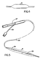
- the balloon After formation of the balloon, the balloon is cooled, dried, the end portions are cut away, e.g., the portions extending outwardly from the smallest diameter of the necked down region, and the balloon 21 is assembled upon a suitable catheter 23 which has a balloon inflation lumen 25 for inflation of the balloon and a through lumen 27 for receiving a guidewire, see Fig. 5. Radiopaque markers 29 are provided on the catheter at the ends of the main body of the balloon 21. In this manner, a large balloon, e.g., of 8 mm diameter, capable of pressure of, e.g., 8 atmospheres can be obtained, having transition regions that are sufficiently thin to enable very successful dilatation.
- a large balloon e.g., of 8 mm diameter, capable of pressure of, e.g., 8 atmospheres can be obtained, having transition regions that are sufficiently thin to enable very successful dilatation.
- a further advantage of the invention is obtained when making the larger balloon sizes for assembly on small catheters, for instance an 8 mm balloon on a 5 French catheter.
- a starting tube of diameter greater than the outer diameter of the catheter on which the balloon is ultimately to be mounted By use of the drawing steps to form the preform, it is readily possible, in the defined heated regions, to draw the diameter of these regions to a size corresponding to the size of the catheter.
- the wall thickness of the tapered section can be increased or decreased according to the amount of draw performed during fabrication of the preform.
- the use of constraining elements in the end regions may be omitted and in other embodiments the entire preform may be confined in a mold for determining the final blown shape.
- the temperature in other embodiments may be outside of the preferred ranges mentioned, provided certain relationships are maintained as described in the summary of the invention, above, with reference to the thermal analysis curve for the respective resin; see the example for the preferred embodiment, Figure 6.
Abstract
Description
- The invention relates to medical balloons and especially to angioplasty dilatation balloon catheters.
- Such balloons are intended to be collapsed to small size about their long supporting devices. In the case, e.g., of angioplasty balloon catheters, the small size is necessary to enable advance of the catheter through narrow and curved blood vessels into the region of stenosis where the balloon is to be inflated. After use, the balloon must be deflated and withdrawn. It is important in such movements not to damage the vessel walls or other delicate tissue of the body.
- The process of making such balloons usually starts with an extruded cylindrical tube of a given diameter and wall thickness. The tube, in its amorphous state, is heated to blowing temperature and inflated and drawn longitudinally. Thus a tube of amorphous polyethylene terephthalate can be drawn and expanded to achieve a wall thickness of less than .001 inch in the main body of the balloon with wall thicknesses that increase in the tapered proximal and distal transition regions.
- Whereas such balloons have been found to be quite useful, especially when high strength resins are employed to provide correspondingly high pressures of inflation, there have been disadvantages attributable to the thickness of the balloon material in the transition regions.
- During folding of the balloon and wrapping it around the catheter shaft to make it small size for insertion, protruding bumps or distortions occur at the ends of the balloon. Because of the thickness of the material at these regions, these distortions can be relatively stiff and sharp and can cause trauma to the arteries or other passages through which the balloon is passed.
- One area in which improvement is particularly needed in this regard is that of large diameter, high pressure angioplasty balloon catheters , i.e., balloon catheters in which the diameter of the main body of the balloon, when inflated, is between about 5 to 12 millimeters.
- Also, known techniques have made it difficult to achieve balloon catheters for other applications, for instance, balloon catheters that require elongated sleeves to fit tightly over very small catheters.
- According to one aspect of the invention, a method of forming an inflatable medical balloon and a product made according to that method is characterized by the steps of providing a tube of a selected resin of wall thickness and diameter suitable for being formed into a ballon, selectively heating to drawing temperature a defined region of the tube at one or both ends of the portion of the tube from which the balloon is to be formed, applying tension in opposite directions to respective ends of the heated region to draw the region to a smaller diameter, thereby providing a preform having, at one or both ends of the portion of tube, a tapered, relatively small diameter region comprised of material that has substantially no crystallization or molecular orientation, thereafter heating the tubular preform to blowing temperature and, while heated, forming a balloon by drawing and blowing the preform including the tapered regions and mounting the balloon to form a balloon catheter device, the step of preforming the tapered end regions enabling the corresponding sections of the blown balloon to have a separately controllable thickness profile.
- In preferred embodiments of this aspect of the invention, the drawing temperature is near or above the glass transition temperature and below crystallization temperature such that substantially no crystallization or molecular orientation occurs; the drawing temperature is near or above the melt temperature of the resin and after drawing, the balloon is rapidly quenched; the blowing temperature is approximately the glass transition temperture or above, and substantially below the crystallization temperature of the resin; for biaxially orienting the balloon, the blowing temperature is below the drawing temperature, in the region of the glass transition temperature of the resin; the resin is amorphous polyethylene terephthalate, the drawing temperature is between about 105 and 130 degrees centigrade and the blowing temperature is between about 85 and 115 degrees centigrade; the drawing to form the preform and the step of drawing and blowing the preform are so related that the wall thickness of the main body of the balloon and the wall thickness of a tapered transition section of the balloon are of substantially equal value or the wall of the transition section is thinner; the heating of the defined region is performed in such a manner that the portion of the tube from which the main body of the balloon is to be formed is not substantially heated.
- According to another aspect of the invention, a dilatation balloon catheter for angioplasty is provided comprising an elongated, small diameter catheter adapted to be passed through the vascular system of the body to a point of stenotic occlusion of a blood vessel, an inflatable dilatation balloon secured about the catheter, adapted to be inflated at the point of occlusion to enlarge the blood vessel and relieve the restriction to blood flow, the balloon comprising a main body section of full diameter and at least one tapering transition section at one end of the main body section, and means to inflate and deflate the balloon, the catheter being characterized in that the balloon is the product of the process of blowing and drawing a preformed tubular member having a tapered contour in the region corresponding to the transition section of the blown balloon.
- In preferred embodiments of this aspect of the invention the preformed tubular member is the product of heating and drawing a defined region of an extruded tube of originally constant diameter and wall thickness; the main body section and the tapering transition section of the balloon have substantially the same wall thickness or the transition section is thinner; the main body of the balloon has an inflated diameter of 5 mm or larger; and the resin from which the balloon is formed is polyethylene terephthalate.
- We first briefly describe the drawings.
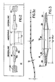
- Figure 1 is a diagramatic view of an extrusion-formed tubular element of a selected resin material being heated and drawn as a step of the present invention.
- Figure 1a is a diagramatic view of a drawn section of the tubular element.
- Figure 1b is an alternate view similar to 1a of another form with a more elongated necked-down region than shown in Figure 1a.
- Figure 1c is a view on a smaller scale showing the entire preform with two necked-down regions separated by a distance L.
- Figure 2 is a diagramatic view of the preform of Figure 1c in a postion ready to be blown into a balloon.
- Figure 3 is a view similar to Figure 2 but in cross-section showing the formed balloon.
- Figure 3a is a cross-section of the wall of the balloon of Figure 3 showning the generally uniform wall thickness achievable along the length of the tube.
- Figure 4 is a side view of a finished balloon produced according to the invention.
- Fig. 5 is a similar view of an angioplasty balloon catheter according to the invention.
- Fig. 6 is a thermal analysis curve of PET resin.
- Referring to Figure 1, a tube suitable for blowing a medical balloon of 8mm diameter is provided, comprised of a nondistendable resin, Goodyear's Clear Tuf 8006, polyethylene terephthalate, having an outer diameter of 0.066 inches and a wall thickness of 0.011 inches. A
portion 10a of the tube, up to line B has been crystallized to render it dimensionally stable under heated conditions. The portion thus stabilized can not be appreciably inflated or drawn. Thetube 10 is immersed in aheated bath 12 of glycerine at a drawing temperature selected from the range of about 105 to 130 degrees centigrade, e.g., 120 degrees centigrade. The crystallized region is fully immersed together with a short portion, Di, e.g., 3 mm, of the amorphous portion 10b of the tube. The portion of the tube out of the bath is gripped by afixed clamp 14, and the crystallized portion of the tube submerged in the bath is gripped by amoveable clamp 16. After a suitable duration of immersion, to ensure that the resin reaches the temperature of the bath,clamp 16 is moved downwardly a predetermined distance, e.g., 2 mm, at a draw rate in the range of about one inch to 0.1 inch per minute, e.g., 0.3 inch per minute, in the direction of the arrow, causing the heated amorphous portion of the tube to be drawn, the crystallized portion resisting such deformation. Referring to Figure 1a,tube 10, in the region between A and B as shown in Figure 1, is necked-down as a result of such drawing. The degree of necking and thinning of the walls obviously depends upon the conditions of drawing, e.g., the drawing rate, drawing temperature, length of the amorphous portion being drawn and the distance of draw, the values of which for any particular balloon can be determined by ready trial. In the preferred embodiment being described, the tube's outer diameter, ODd, is necked-down to 0.054 inch and the tube is lengthened 2 mm. In the alternative embodiment of Figure 1b in which a longer portion of the amorphous tube has been immersed, the tube is drawn down to aconstant diameter sleeve 19. - After the initial necking-down of the tube, the tube is reversed in the bath and the second necked-down portion is formed by the same procedure, at a point spaced along the amorphous tube a distance L, e.g., 0.57 inch, to provide a section of tube between the necked-down regions which will be drawn and blown in forming the main body of the balloon. This procedure can provide a preform in which the thickness of the wall of the tube in the region of the drawn-down deformation decreases with decrease in diameter.
- After the preform is completed, it is submerged in a second bath of glycerine as shown in Figure 2, this time arranged horizontally, and with the tube extending through two stationary constraining
elements 18, the crystallized portions of the tube being grasped byclamps element 18 is comprised of a cylindrical portion 18a and aconical portion 18b, the wide ends of the conical portions being opposed to each other, arranged to define the shape of the tapered sections of the balloon. - As shown, the crystallized regions of the tube end at points C and D in the initial setup of Figure 2. After the temperature of the tube has stabilized in bath 12a, the two
clamps elements 18 as it is lengthened. Simultaneously, gas pressure is applied to the interior of the tube , causing it to expand. The region, L, of the tube expands without constraint until the molecules of the wall material in the balloon region become stabilized in a biaxially oriented condition. In its final form, the balloon reaches an OD of 8mm and the length between the tapered sections, increases to L + Δ L = 1.51 inches. The portions of the tube having the preformed tapers also expand until they are constrained to the shape of constrainingelement 18. The final balloon thickness profile is illustrated in Figure 3a in which the thickness of the balloon tb is 0.0007 inches and the thickness tt of the tapered wall is substantially of the same value with variation less than about 0.0001 inch. The length of the amorphous region during the blow and draw step increases from L₂ = 0.94 inch to L₂ + ΔL₂ = 2.70 inch. - In another embodiment, in forming the preform, e.g., by drawing more on the defined region, and thus drawing the taper down further, it is possible to achieve in the blown balloon a wall thickness of the transition region that is less than that of the main body of the balloon.
- After formation of the balloon, the balloon is cooled, dried, the end portions are cut away, e.g., the portions extending outwardly from the smallest diameter of the necked down region, and the
balloon 21 is assembled upon a suitable catheter 23 which has aballoon inflation lumen 25 for inflation of the balloon and a throughlumen 27 for receiving a guidewire, see Fig. 5.Radiopaque markers 29 are provided on the catheter at the ends of the main body of theballoon 21. In this manner, a large balloon, e.g., of 8 mm diameter, capable of pressure of, e.g., 8 atmospheres can be obtained, having transition regions that are sufficiently thin to enable very successful dilatation. - A further advantage of the invention is obtained when making the larger balloon sizes for assembly on small catheters, for instance an 8 mm balloon on a 5 French catheter. To form such a balloon, it is advantageous to choose a starting tube of diameter greater than the outer diameter of the catheter on which the balloon is ultimately to be mounted. By use of the drawing steps to form the preform, it is readily possible, in the defined heated regions, to draw the diameter of these regions to a size corresponding to the size of the catheter.
- In the other embodiments the wall thickness of the tapered section can be increased or decreased according to the amount of draw performed during fabrication of the preform. In some embodiments the use of constraining elements in the end regions may be omitted and in other embodiments the entire preform may be confined in a mold for determining the final blown shape. The temperature in other embodiments may be outside of the preferred ranges mentioned, provided certain relationships are maintained as described in the summary of the invention, above, with reference to the thermal analysis curve for the respective resin; see the example for the preferred embodiment, Figure 6.
- For certain of the broader aspects of the invention, other forming techniques such as molding of a softened tube are possible for preparing the tapered preform.
Claims (17)
said step of preforming said tapered end region enabling the corresponding section of the blown balloon to have a separately controllable thickness profile.
said step of preforming said tapered end regions enabling the corresponding sections of the blown balloon to have a separately controllable thickness profile.
a) an elongated, small diameter catheter adapted to be passed through the vascular system of the body to a point of stenotic occlusion of a blood vessel,
b) an inflatable dilatation balloon secured about said catheter, adapted to be inflated at said point of occlusion to enlarge the blood vessel and relieve the restriction to blood flow, said balloon comprising a main body section of full diameter and at least one tapering transition section at one end of said main body section,
c) and means to inflate and deflate said balloon
said catheter characterized in that said balloon is the product of the process of blowing and drawing a preformed tubular member having a tapered contour in the region corresponding to the transition section of the blown balloon.
Priority Applications (1)
| Application Number | Priority Date | Filing Date | Title |
|---|---|---|---|
| AT88119884T ATE100340T1 (en) | 1987-11-30 | 1988-11-29 | BALLOON CATHETER. |
Applications Claiming Priority (2)
| Application Number | Priority Date | Filing Date | Title |
|---|---|---|---|
| US126769 | 1980-03-03 | ||
| US07/126,769 US4963313A (en) | 1987-11-30 | 1987-11-30 | Balloon catheter |
Publications (3)
| Publication Number | Publication Date |
|---|---|
| EP0318919A2 true EP0318919A2 (en) | 1989-06-07 |
| EP0318919A3 EP0318919A3 (en) | 1990-01-24 |
| EP0318919B1 EP0318919B1 (en) | 1994-01-19 |
Family
ID=22426558
Family Applications (1)
| Application Number | Title | Priority Date | Filing Date |
|---|---|---|---|
| EP88119884A Expired - Lifetime EP0318919B1 (en) | 1987-11-30 | 1988-11-29 | Balloon catheter |
Country Status (10)
| Country | Link |
|---|---|
| US (1) | US4963313A (en) |
| EP (1) | EP0318919B1 (en) |
| JP (1) | JPH024387A (en) |
| CN (1) | CN1020408C (en) |
| AT (1) | ATE100340T1 (en) |
| CA (1) | CA1303449C (en) |
| DE (1) | DE3887295T2 (en) |
| DK (1) | DK170794B1 (en) |
| ES (1) | ES2048189T3 (en) |
| NO (1) | NO173806C (en) |
Cited By (17)
| Publication number | Priority date | Publication date | Assignee | Title |
|---|---|---|---|---|
| WO1996012516A1 (en) * | 1994-10-19 | 1996-05-02 | Advanced Cardiovascular Systems, Inc. | High strength dilatation balloons |
| WO1998005377A1 (en) * | 1996-08-02 | 1998-02-12 | Btg International Limited | Balloon catheter |
| US5951941A (en) * | 1994-03-02 | 1999-09-14 | Scimed Life Systems, Inc. | Block copolymer elastomer catheter balloons |
| WO1999058182A1 (en) | 1998-05-11 | 1999-11-18 | Scimed Life Systems, Inc. | Soft flexible tipped balloon |
| EP0974370A1 (en) * | 1990-11-09 | 2000-01-26 | Boston Scientific Corporation | Balloon for medical catheter |
| US6406457B1 (en) | 1994-03-02 | 2002-06-18 | Scimed Life Systems, Inc. | Block copolymer elastomer catheter balloons |
| US6607544B1 (en) | 1994-01-26 | 2003-08-19 | Kyphon Inc. | Expandable preformed structures for deployment in interior body regions |
| US6719773B1 (en) | 1998-06-01 | 2004-04-13 | Kyphon Inc. | Expandable structures for deployment in interior body regions |
| WO2005099803A2 (en) * | 2004-04-07 | 2005-10-27 | Boston Scientific Limited | Balloon catheters and methods for manufacturing balloons for balloon catheters |
| US7163522B1 (en) | 1994-03-02 | 2007-01-16 | Scimed Life Systems, Inc. | Block copolymer elastomer catheter balloons |
| US7252650B1 (en) | 1996-08-02 | 2007-08-07 | Ranier Limited | Balloon catheter |
| US7261720B2 (en) | 2002-01-11 | 2007-08-28 | Kyphon Inc. | Inflatable device for use in surgical protocol relating to fixation of bone |
| US7306616B2 (en) | 2003-05-05 | 2007-12-11 | Boston Scientific Scimed, Inc. | Balloon catheter and method of making same |
| US7771450B2 (en) | 1998-05-11 | 2010-08-10 | Boston Scientific Scimed, Inc. | Balloon cones and waists thinning methodology |
| US8986339B2 (en) | 2005-06-17 | 2015-03-24 | Abbott Laboratories | Method of reducing rigidity of angioplasty balloon sections |
| EP2813256A4 (en) * | 2012-02-09 | 2015-09-16 | Kaneka Corp | Balloon tube, balloon, balloon catheter, and balloon tube fabrication method |
| US9555224B2 (en) | 2013-03-15 | 2017-01-31 | Abbott Cardiovascular Systems Inc. | Reduced material tip for catheter and method of forming same |
Families Citing this family (135)
| Publication number | Priority date | Publication date | Assignee | Title |
|---|---|---|---|---|
| US5358486A (en) * | 1987-01-09 | 1994-10-25 | C. R. Bard, Inc. | Multiple layer high strength balloon for dilatation catheter |
| DE69002295T2 (en) | 1989-09-25 | 1993-11-04 | Schneider Usa Inc | MULTILAYER EXTRUSION AS A METHOD FOR PRODUCING BALLOONS FOR VESSEL PLASTICS. |
| US5045061A (en) * | 1990-02-02 | 1991-09-03 | C. R. Bard, Inc. | Balloon catheter and locking guidewire system |
| US5163989A (en) * | 1990-08-27 | 1992-11-17 | Advanced Cardiovascular Systems, Inc. | Method for forming a balloon mold and the use of such mold |
| JP2555298B2 (en) * | 1990-11-10 | 1996-11-20 | テルモ株式会社 | CATHETER BALLOON, CATHETER BALLOON MANUFACTURING METHOD, AND BALLOON CATHETER |
| US5254091A (en) * | 1991-01-08 | 1993-10-19 | Applied Medical Resources Corporation | Low profile balloon catheter and method for making same |
| US5195969A (en) | 1991-04-26 | 1993-03-23 | Boston Scientific Corporation | Co-extruded medical balloons and catheter using such balloons |
| WO1992019440A1 (en) * | 1991-05-01 | 1992-11-12 | Danforth Biomedical, Inc. | Improved balloon catheter of low molecular weight pet |
| US5330428A (en) * | 1991-05-14 | 1994-07-19 | Scimed Life Systems, Inc. | Dilatation catheter having a random copolymer balloon |
| US5264260A (en) * | 1991-06-20 | 1993-11-23 | Saab Mark A | Dilatation balloon fabricated from low molecular weight polymers |
| US5267959A (en) * | 1991-11-29 | 1993-12-07 | Schneider, Inc. | Laser bonding of angioplasty balloon catheters |
| US5649909A (en) * | 1992-04-06 | 1997-07-22 | Scimed Life Systems, Inc. | Variable stiffness multi-lumen catheter |
| US5348538A (en) * | 1992-09-29 | 1994-09-20 | Scimed Life Systems, Inc. | Shrinking balloon catheter having nonlinear or hybrid compliance curve |
| US5500180A (en) * | 1992-09-30 | 1996-03-19 | C. R. Bard, Inc. | Method of making a distensible dilatation balloon using a block copolymer |
| US5634901A (en) * | 1992-11-02 | 1997-06-03 | Localmed, Inc. | Method of using a catheter sleeve |
| US6896842B1 (en) | 1993-10-01 | 2005-05-24 | Boston Scientific Corporation | Medical device balloons containing thermoplastic elastomers |
| EP0738168B1 (en) | 1993-10-01 | 2004-01-21 | Boston Scientific Corporation | Medical device balloons containing thermoplastic elastomers |
| DE4480681T1 (en) | 1994-02-17 | 1996-04-25 | Scimed Life Systems Inc | Process for the production of catheter balloons |
| US5849846A (en) * | 1994-07-25 | 1998-12-15 | Advanced Cardiovascular Systems, Inc. | Balloons for medical catheters |
| US5554120A (en) * | 1994-07-25 | 1996-09-10 | Advanced Cardiovascular Systems, Inc. | Polymer blends for use in making medical devices including catheters and balloons for dilatation catheters |
| JPH0838618A (en) * | 1994-07-29 | 1996-02-13 | Nippon Zeon Co Ltd | Balloon catheter for expanding celom and its production |
| ES2144574T3 (en) * | 1994-10-20 | 2000-06-16 | Interventional Technologies | PROCEDURE FOR THE MANUFACTURE OF A POLYMER MATERIAL WITH IMPROVED MECHANICAL PROPERTIES. |
| JP3766122B2 (en) * | 1995-08-04 | 2006-04-12 | 株式会社カネカ | Catheter balloon and manufacturing method thereof |
| WO1997017098A1 (en) * | 1995-11-08 | 1997-05-15 | Scimed Life Systems, Inc. | Method of balloon formation by cold drawing/necking |
| US5733301A (en) * | 1996-01-11 | 1998-03-31 | Schneider (Usa) Inc. | Laser ablation of angioplasty catheters and balloons |
| EP0835673A3 (en) | 1996-10-10 | 1998-09-23 | Schneider (Usa) Inc. | Catheter for tissue dilatation and drug delivery |
| US7101597B2 (en) | 1997-09-10 | 2006-09-05 | Boston Scientific Scimed, Inc. | Medical devices made from polymer blends containing low melting temperature liquid crystal polymers |
| US6284333B1 (en) | 1997-09-10 | 2001-09-04 | Scimed Life Systems, Inc. | Medical devices made from polymer blends containing low melting temperature liquid crystal polymers |
| US6358227B1 (en) | 1997-09-10 | 2002-03-19 | Scimed Life Systems, Inc. | Dilatation catheter balloon made from pen based homopolymer or random copolymer |
| US6242063B1 (en) | 1997-09-10 | 2001-06-05 | Scimed Life Systems, Inc. | Balloons made from liquid crystal polymer blends |
| US6048338A (en) * | 1997-10-15 | 2000-04-11 | Scimed Life Systems, Inc. | Catheter with spiral cut transition member |
| US5948345A (en) * | 1998-01-05 | 1999-09-07 | Medtronic, Inc. | Method for making medical balloon catheter |
| US6176698B1 (en) | 1998-02-24 | 2001-01-23 | Medtronic Ave, Inc. | Thin cone balloons through a unique mold design |
| EP1059948B1 (en) | 1998-03-04 | 2004-02-18 | Boston Scientific Limited | Composition and process for manufacturing pbt catheter balloons |
| US6416494B1 (en) | 1998-06-11 | 2002-07-09 | Infinity Extrusion & Engineering, Inc. | Semi-compliant catheter balloons and methods of manufacture thereof |
| WO2000020063A1 (en) * | 1998-10-05 | 2000-04-13 | Kaneka Corporation | Balloon catheter and production method therefor |
| WO2000027461A1 (en) * | 1998-11-09 | 2000-05-18 | Datascope Investment Corp. | Intra-aortic balloon catheter having an ultra-thin stretch blow molded balloon membrane |
| US6443925B1 (en) | 1999-09-13 | 2002-09-03 | Advanced Cardiovascular Systems, Inc. | Balloon catheter shaft formed of liquid crystal polymeric material blend |
| US6325780B1 (en) | 1999-09-13 | 2001-12-04 | Advanced Cardiovascular Systems, Inc. | Inflatable member formed of liquid crystal polymeric material blend |
| US6592550B1 (en) | 1999-09-17 | 2003-07-15 | Cook Incorporated | Medical device including improved expandable balloon |
| US6977103B2 (en) * | 1999-10-25 | 2005-12-20 | Boston Scientific Scimed, Inc. | Dimensionally stable balloons |
| US6881209B2 (en) | 2000-05-25 | 2005-04-19 | Cook Incorporated | Medical device including unitary, continuous portion of varying durometer |
| NL1018018C2 (en) * | 2001-05-08 | 2002-11-19 | Blue Medical Devices B V | Balloon catheter and method for manufacturing thereof. |
| NL1018881C2 (en) * | 2001-05-08 | 2002-11-25 | Blue Medical Devices B V | Balloon catheter for dilating vessels and lumina comprise inflatable balloon with ends attached to it's catheter tube |
| US6946092B1 (en) * | 2001-09-10 | 2005-09-20 | Scimed Life Systems, Inc. | Medical balloon |
| US7201763B2 (en) | 2001-10-24 | 2007-04-10 | Boston Scientific Scimed, Inc. | Distal balloon waist material relief and method of manufacture |
| US7037562B2 (en) * | 2002-01-14 | 2006-05-02 | Vascon Llc | Angioplasty super balloon fabrication with composite materials |
| US6730377B2 (en) | 2002-01-23 | 2004-05-04 | Scimed Life Systems, Inc. | Balloons made from liquid crystal polymer blends |
| US7005097B2 (en) * | 2002-01-23 | 2006-02-28 | Boston Scientific Scimed, Inc. | Medical devices employing chain extended polymers |
| US7029732B2 (en) | 2002-02-28 | 2006-04-18 | Boston Scientific Scimed, Inc. | Medical device balloons with improved strength properties and processes for producing same |
| US8337968B2 (en) | 2002-09-11 | 2012-12-25 | Boston Scientific Scimed, Inc. | Radiation sterilized medical devices comprising radiation sensitive polymers |
| US7037319B2 (en) * | 2002-10-15 | 2006-05-02 | Scimed Life Systems, Inc. | Nanotube paper-based medical device |
| US6835189B2 (en) * | 2002-10-15 | 2004-12-28 | Scimed Life Systems, Inc. | Controlled deployment balloon |
| WO2004091471A2 (en) | 2003-04-04 | 2004-10-28 | Berger, Constance, F. | Apparatus for heating bottles and method of manufacturing same |
| US7279002B2 (en) * | 2003-04-25 | 2007-10-09 | Boston Scientific Scimed, Inc. | Cutting stent and balloon |
| US7727442B2 (en) * | 2003-07-10 | 2010-06-01 | Boston Scientific Scimed, Inc. | Medical device tubing with discrete orientation regions |
| US9180620B2 (en) | 2003-08-21 | 2015-11-10 | Boston Scientific Scimed, Inc. | Medical balloons |
| US20050124976A1 (en) * | 2003-12-04 | 2005-06-09 | Devens Douglas A.Jr. | Medical devices |
| US20050127561A1 (en) * | 2003-12-16 | 2005-06-16 | Scimed Life Systems, Inc. | Method of making expandable-collapsible bodies by temperature gradient expansion molding |
| US20050137619A1 (en) * | 2003-12-19 | 2005-06-23 | Scott Schewe | Molds and related methods and articles |
| US7264458B2 (en) * | 2004-01-07 | 2007-09-04 | Boston Scientific Scimed, Inc. | Process and apparatus for forming medical device balloons |
| US7016394B2 (en) * | 2004-04-23 | 2006-03-21 | Ucar Carbon Company Inc. | Male-female electrode joint |
| DE602005005090T2 (en) * | 2004-01-22 | 2009-03-19 | Nipro Corp., Osaka | balloon catheter |
| US8620406B2 (en) * | 2004-01-23 | 2013-12-31 | Boston Scientific Scimed, Inc. | Medical devices visible by magnetic resonance imaging |
| US7713233B2 (en) * | 2004-04-12 | 2010-05-11 | Boston Scientific Scimed, Inc. | Balloons having a crosslinkable layer |
| US8353867B2 (en) * | 2004-05-04 | 2013-01-15 | Boston Scientific Scimed, Inc. | Medical devices |
| US7758572B2 (en) | 2004-05-20 | 2010-07-20 | Boston Scientific Scimed, Inc. | Medical devices and methods including cooling balloons having nanotubes |
| US20050260355A1 (en) * | 2004-05-20 | 2005-11-24 | Jan Weber | Medical devices and methods of making the same |
| US8043259B2 (en) * | 2004-05-24 | 2011-10-25 | Boston Scientific Scimed, Inc. | Medical device systems |
| US7976557B2 (en) * | 2004-06-23 | 2011-07-12 | Boston Scientific Scimed, Inc. | Cutting balloon and process |
| US7635510B2 (en) * | 2004-07-07 | 2009-12-22 | Boston Scientific Scimed, Inc. | High performance balloon catheter/component |
| US7435077B2 (en) * | 2004-08-13 | 2008-10-14 | Boston Scientific Scimed, Inc. | Catheter balloon molding device |
| US8500797B2 (en) * | 2004-09-08 | 2013-08-06 | Boston Scientific Scimed, Inc. | Medical devices |
| US7722578B2 (en) * | 2004-09-08 | 2010-05-25 | Boston Scientific Scimed, Inc. | Medical devices |
| US7291158B2 (en) | 2004-11-12 | 2007-11-06 | Boston Scientific Scimed, Inc. | Cutting balloon catheter having a segmented blade |
| US8038691B2 (en) | 2004-11-12 | 2011-10-18 | Boston Scientific Scimed, Inc. | Cutting balloon catheter having flexible atherotomes |
| US8066726B2 (en) * | 2004-11-23 | 2011-11-29 | Boston Scientific Scimed, Inc. | Serpentine cutting blade for cutting balloon |
| US8202245B2 (en) * | 2005-01-26 | 2012-06-19 | Boston Scientific Scimed, Inc. | Medical devices and methods of making the same |
| US20060184191A1 (en) | 2005-02-11 | 2006-08-17 | Boston Scientific Scimed, Inc. | Cutting balloon catheter having increased flexibility regions |
| US20060182873A1 (en) * | 2005-02-17 | 2006-08-17 | Klisch Leo M | Medical devices |
| US8048028B2 (en) * | 2005-02-17 | 2011-11-01 | Boston Scientific Scimed, Inc. | Reinforced medical balloon |
| US20060247674A1 (en) * | 2005-04-29 | 2006-11-02 | Roman Ricardo D | String cutting balloon |
| US7691082B2 (en) * | 2005-07-01 | 2010-04-06 | Boston Scientific Scimed, Inc. | Medical devices |
| US7778684B2 (en) * | 2005-08-08 | 2010-08-17 | Boston Scientific Scimed, Inc. | MRI resonator system with stent implant |
| US8034066B2 (en) * | 2005-09-15 | 2011-10-11 | Boston Scientific Scimed, Inc. | Multi-layer medical balloons |
| US20070073328A1 (en) * | 2005-09-26 | 2007-03-29 | Wilson-Cook Medical Inc., | Incrementally expandable balloon |
| US20070085244A1 (en) * | 2005-10-17 | 2007-04-19 | Chul Hi Park | Method for making inflatable hollow bodies |
| US7828766B2 (en) | 2005-12-20 | 2010-11-09 | Advanced Cardiovascular Systems, Inc. | Non-compliant multilayered balloon for a catheter |
| US9526814B2 (en) * | 2006-02-16 | 2016-12-27 | Boston Scientific Scimed, Inc. | Medical balloons and methods of making the same |
| US20070191931A1 (en) * | 2006-02-16 | 2007-08-16 | Jan Weber | Bioerodible endoprostheses and methods of making the same |
| US8043673B2 (en) | 2006-03-02 | 2011-10-25 | Boston Scientific Scimed, Inc. | Method to make tube-in-tube balloon |
| US20070205539A1 (en) * | 2006-03-03 | 2007-09-06 | Boston Scientific Scimed, Inc. | Balloon mold design |
| US20070207182A1 (en) * | 2006-03-06 | 2007-09-06 | Jan Weber | Medical devices having electrically aligned elongated particles |
| US20070239256A1 (en) * | 2006-03-22 | 2007-10-11 | Jan Weber | Medical devices having electrical circuits with multilayer regions |
| US20070245298A1 (en) * | 2006-04-18 | 2007-10-18 | International Business Machines Corporation | Apparatus and data structure for automatic workflow composition |
| US8858855B2 (en) | 2006-04-20 | 2014-10-14 | Boston Scientific Scimed, Inc. | High pressure balloon |
| US7943221B2 (en) * | 2006-05-22 | 2011-05-17 | Boston Scientific Scimed, Inc. | Hinged compliance fiber braid balloon |
| US8434487B2 (en) | 2006-06-22 | 2013-05-07 | Covidien Lp | Endotracheal cuff and technique for using the same |
| US8196584B2 (en) | 2006-06-22 | 2012-06-12 | Nellcor Puritan Bennett Llc | Endotracheal cuff and technique for using the same |
| US7654264B2 (en) | 2006-07-18 | 2010-02-02 | Nellcor Puritan Bennett Llc | Medical tube including an inflatable cuff having a notched collar |
| JP4752657B2 (en) * | 2006-07-25 | 2011-08-17 | ニプロ株式会社 | Catheter balloon and manufacturing method thereof |
| US8926620B2 (en) | 2006-08-25 | 2015-01-06 | Kyphon Sarl | Apparatus and methods for use of expandable members in surgical applications |
| US8043296B2 (en) | 2006-08-25 | 2011-10-25 | Kyphon Sarl | Apparatus and methods for use of expandable members in surgical applications |
| US7963942B2 (en) * | 2006-09-20 | 2011-06-21 | Boston Scientific Scimed, Inc. | Medical balloons with modified surfaces |
| US8684175B2 (en) | 2006-09-22 | 2014-04-01 | Covidien Lp | Method for shipping and protecting an endotracheal tube with an inflated cuff |
| US8561614B2 (en) | 2006-09-28 | 2013-10-22 | Covidien Lp | Multi-layer cuffs for medical devices |
| US7950393B2 (en) | 2006-09-29 | 2011-05-31 | Nellcor Puritan Bennett Llc | Endotracheal cuff and technique for using the same |
| US8807136B2 (en) | 2006-09-29 | 2014-08-19 | Covidien Lp | Self-sizing adjustable endotracheal tube |
| US8307830B2 (en) | 2006-09-29 | 2012-11-13 | Nellcor Puritan Bennett Llc | Endotracheal cuff and technique for using the same |
| US20080078399A1 (en) | 2006-09-29 | 2008-04-03 | O'neil Michael P | Self-sizing adjustable endotracheal tube |
| US20080078405A1 (en) | 2006-09-29 | 2008-04-03 | Crumback Gary L | Self-sizing adjustable endotracheal tube |
| US20080091073A1 (en) * | 2006-10-16 | 2008-04-17 | Chul Hi Park | Inflatable actuation device |
| US20080275299A1 (en) * | 2007-05-01 | 2008-11-06 | Chul Hi Park | Actuation device |
| EP2197508B1 (en) * | 2007-09-06 | 2014-12-10 | Boston Scientific Limited | Medical devices containing silicate and carbon particles |
| US20090209908A1 (en) * | 2007-09-20 | 2009-08-20 | Cuevas Brian J | Tubular workpiece for producing an improved balloon cuff tracheostomy tube |
| US20090131752A1 (en) * | 2007-11-19 | 2009-05-21 | Chul Hi Park | Inflatable artificial muscle for elongated instrument |
| US8750978B2 (en) | 2007-12-31 | 2014-06-10 | Covidien Lp | System and sensor for early detection of shock or perfusion failure and technique for using the same |
| US9039748B2 (en) * | 2008-04-07 | 2015-05-26 | Abbott Cardiovascular Systems Inc. | Method of securing a medical device onto a balloon and system thereof |
| WO2009149405A1 (en) | 2008-06-05 | 2009-12-10 | Boston Scientific Scimed, Inc. | Balloon bifurcated lumen treatment |
| JP5662310B2 (en) | 2008-06-05 | 2015-01-28 | ボストン サイエンティフィック サイムド,インコーポレイテッドBoston Scientific Scimed,Inc. | Shrinkable branch device and method of manufacturing the same |
| US20090318863A1 (en) * | 2008-06-18 | 2009-12-24 | Boston Scientific Scimed, Inc. | Functional Balloon With Built in Lubricity or Drug Delivery System |
| US8500687B2 (en) | 2008-09-25 | 2013-08-06 | Abbott Cardiovascular Systems Inc. | Stent delivery system having a fibrous matrix covering with improved stent retention |
| US8590534B2 (en) | 2009-06-22 | 2013-11-26 | Covidien Lp | Cuff for use with medical tubing and method and apparatus for making the same |
| US8703260B2 (en) | 2010-09-14 | 2014-04-22 | Abbott Cardiovascular Systems Inc. | Catheter balloon and method for forming same |
| US9662677B2 (en) | 2010-09-15 | 2017-05-30 | Abbott Laboratories | Drug-coated balloon with location-specific plasma treatment |
| US10207449B2 (en) | 2014-06-24 | 2019-02-19 | Cook Medical Technologies Llc | Sequential biaxial strain of semi-crystalline tubes |
| JP2017529962A (en) * | 2014-10-02 | 2017-10-12 | アーヘン サイエンティフィック インターナショナル ピーティーイー.リミテッド | Cutback method for endovascular dilatation catheters |
| US9808598B2 (en) | 2015-02-04 | 2017-11-07 | Teleflex Medical Incorporated | Flexible tip dilator |
| WO2017180639A1 (en) | 2016-04-12 | 2017-10-19 | Boston Scientific Scimed, Inc. | Medical balloon |
| US10849629B2 (en) | 2016-12-13 | 2020-12-01 | Boston Scientific Scimed, Inc. | Medical balloon |
| WO2018181323A1 (en) * | 2017-03-31 | 2018-10-04 | 日本ゼオン株式会社 | Parison production method and parison production apparatus |
| EP3615099B1 (en) | 2017-04-25 | 2023-03-01 | Boston Scientific Scimed, Inc. | Medical balloon |
| CN107754074B (en) * | 2017-11-15 | 2020-04-10 | 董鹏 | Directional blasting balloon |
| CN111700659A (en) * | 2020-05-06 | 2020-09-25 | 中国人民解放军陆军军医大学第一附属医院 | Intracavitary blood vessel flow guiding device |
| IT202000025915A1 (en) | 2020-10-30 | 2022-04-30 | I Vasc Srl | MATRIX FOR A MOLD FOR FORMING AN EXPANDABLE BALLOON FOR INTRALUMINAL USE, BALLOON AND METHOD |
Citations (3)
| Publication number | Priority date | Publication date | Assignee | Title |
|---|---|---|---|---|
| DE2916097C2 (en) * | 1978-04-24 | 1985-12-05 | Advanced Cardiovascular Systems, Inc., Mountain View, Calif. | Method of manufacturing a dilatation catheter |
| EP0274411A2 (en) * | 1987-01-09 | 1988-07-13 | C.R. Bard, Inc. | Thin wall high strength balloon and method of manufacture |
| EP0135990B1 (en) * | 1983-07-05 | 1990-09-26 | C.R. Bard, Inc. | Balloon and manufacture thereof |
Family Cites Families (8)
| Publication number | Priority date | Publication date | Assignee | Title |
|---|---|---|---|---|
| US3865666A (en) * | 1973-05-08 | 1975-02-11 | Int Paper Co | Method of making a catheter |
| US3950468A (en) * | 1974-08-19 | 1976-04-13 | Dewey Rainville | Injection blow molding of container open at both ends |
| US4323071A (en) * | 1978-04-24 | 1982-04-06 | Advanced Catheter Systems, Inc. | Vascular guiding catheter assembly and vascular dilating catheter assembly and a combination thereof and methods of making the same |
| US4256789B1 (en) * | 1979-07-19 | 1991-03-26 | Injection molded,polyethylene terephthalate parison for blow molding | |
| US4411055A (en) * | 1980-05-19 | 1983-10-25 | Advanced Cardiovascular Systems, Inc. | Vascular guiding catheter assembly and vascular dilating catheter assembly and a combination thereof and methods for making the same |
| US4422447A (en) * | 1981-04-13 | 1983-12-27 | Peter Schiff | Percutaneous balloon |
| US4646719A (en) * | 1984-06-11 | 1987-03-03 | Aries Medical Incorporated | Intra-aortic balloon catheter having flexible torque transmitting tube |
| US4587975A (en) * | 1984-07-02 | 1986-05-13 | Cardiac Pacemakers, Inc. | Dimension sensitive angioplasty catheter |
-
1987
- 1987-11-30 US US07/126,769 patent/US4963313A/en not_active Expired - Lifetime
-
1988
- 1988-11-29 ES ES88119884T patent/ES2048189T3/en not_active Expired - Lifetime
- 1988-11-29 AT AT88119884T patent/ATE100340T1/en not_active IP Right Cessation
- 1988-11-29 DK DK665288A patent/DK170794B1/en not_active IP Right Cessation
- 1988-11-29 CN CN88108146A patent/CN1020408C/en not_active Expired - Fee Related
- 1988-11-29 EP EP88119884A patent/EP0318919B1/en not_active Expired - Lifetime
- 1988-11-29 CA CA000584469A patent/CA1303449C/en not_active Expired - Lifetime
- 1988-11-29 NO NO885312A patent/NO173806C/en unknown
- 1988-11-29 DE DE3887295T patent/DE3887295T2/en not_active Expired - Lifetime
- 1988-11-30 JP JP63303883A patent/JPH024387A/en not_active Expired - Lifetime
Patent Citations (3)
| Publication number | Priority date | Publication date | Assignee | Title |
|---|---|---|---|---|
| DE2916097C2 (en) * | 1978-04-24 | 1985-12-05 | Advanced Cardiovascular Systems, Inc., Mountain View, Calif. | Method of manufacturing a dilatation catheter |
| EP0135990B1 (en) * | 1983-07-05 | 1990-09-26 | C.R. Bard, Inc. | Balloon and manufacture thereof |
| EP0274411A2 (en) * | 1987-01-09 | 1988-07-13 | C.R. Bard, Inc. | Thin wall high strength balloon and method of manufacture |
Cited By (26)
| Publication number | Priority date | Publication date | Assignee | Title |
|---|---|---|---|---|
| EP0974370A1 (en) * | 1990-11-09 | 2000-01-26 | Boston Scientific Corporation | Balloon for medical catheter |
| US6979341B2 (en) | 1994-01-26 | 2005-12-27 | Kyphon Inc. | Expandable preformed structures for deployment in interior body regions |
| US6607544B1 (en) | 1994-01-26 | 2003-08-19 | Kyphon Inc. | Expandable preformed structures for deployment in interior body regions |
| US7700033B2 (en) | 1994-03-02 | 2010-04-20 | Boston Scientific Scimed, Inc. | Block copolymer elastomer catheter balloons |
| US5951941A (en) * | 1994-03-02 | 1999-09-14 | Scimed Life Systems, Inc. | Block copolymer elastomer catheter balloons |
| US7618696B2 (en) | 1994-03-02 | 2009-11-17 | Boston Scientific Scimed, Inc. | Block copolymer elastomer catheter balloons |
| US6406457B1 (en) | 1994-03-02 | 2002-06-18 | Scimed Life Systems, Inc. | Block copolymer elastomer catheter balloons |
| US7163522B1 (en) | 1994-03-02 | 2007-01-16 | Scimed Life Systems, Inc. | Block copolymer elastomer catheter balloons |
| WO1996012516A1 (en) * | 1994-10-19 | 1996-05-02 | Advanced Cardiovascular Systems, Inc. | High strength dilatation balloons |
| US7252650B1 (en) | 1996-08-02 | 2007-08-07 | Ranier Limited | Balloon catheter |
| WO1998005377A1 (en) * | 1996-08-02 | 1998-02-12 | Btg International Limited | Balloon catheter |
| US7771450B2 (en) | 1998-05-11 | 2010-08-10 | Boston Scientific Scimed, Inc. | Balloon cones and waists thinning methodology |
| US8357177B2 (en) | 1998-05-11 | 2013-01-22 | Boston Scientific Scimed, Inc. | Balloon cones and waists thinning methodology |
| WO1999058182A1 (en) | 1998-05-11 | 1999-11-18 | Scimed Life Systems, Inc. | Soft flexible tipped balloon |
| US6719773B1 (en) | 1998-06-01 | 2004-04-13 | Kyphon Inc. | Expandable structures for deployment in interior body regions |
| US7875035B2 (en) | 1998-06-01 | 2011-01-25 | Kyphon Sarl | Expandable structures for deployment in interior body regions |
| US7722624B2 (en) | 1998-06-01 | 2010-05-25 | Kyphon SÀRL | Expandable structures for deployment in interior body regions |
| US7261720B2 (en) | 2002-01-11 | 2007-08-28 | Kyphon Inc. | Inflatable device for use in surgical protocol relating to fixation of bone |
| US7306616B2 (en) | 2003-05-05 | 2007-12-11 | Boston Scientific Scimed, Inc. | Balloon catheter and method of making same |
| WO2005099803A3 (en) * | 2004-04-07 | 2006-04-27 | Scimed Life Systems Inc | Balloon catheters and methods for manufacturing balloons for balloon catheters |
| US8034280B2 (en) | 2004-04-07 | 2011-10-11 | Boston Scientific Scimed, Inc. | Balloon catheters and methods for manufacturing balloons for balloon catheters |
| WO2005099803A2 (en) * | 2004-04-07 | 2005-10-27 | Boston Scientific Limited | Balloon catheters and methods for manufacturing balloons for balloon catheters |
| US8986339B2 (en) | 2005-06-17 | 2015-03-24 | Abbott Laboratories | Method of reducing rigidity of angioplasty balloon sections |
| EP2813256A4 (en) * | 2012-02-09 | 2015-09-16 | Kaneka Corp | Balloon tube, balloon, balloon catheter, and balloon tube fabrication method |
| US9555224B2 (en) | 2013-03-15 | 2017-01-31 | Abbott Cardiovascular Systems Inc. | Reduced material tip for catheter and method of forming same |
| EP2968840B1 (en) * | 2013-03-15 | 2018-06-27 | Abbott Cardiovascular Systems Inc. | Method of forming reduced material tip for catheter |
Also Published As
| Publication number | Publication date |
|---|---|
| JPH024387A (en) | 1990-01-09 |
| NO173806C (en) | 1994-02-09 |
| DK170794B1 (en) | 1996-01-22 |
| NO173806B (en) | 1993-11-01 |
| EP0318919B1 (en) | 1994-01-19 |
| US4963313A (en) | 1990-10-16 |
| ES2048189T3 (en) | 1994-03-16 |
| CN1020408C (en) | 1993-05-05 |
| DK665288A (en) | 1989-05-31 |
| CN1034315A (en) | 1989-08-02 |
| DK665288D0 (en) | 1988-11-29 |
| CA1303449C (en) | 1992-06-16 |
| NO885312L (en) | 1989-05-31 |
| ATE100340T1 (en) | 1994-02-15 |
| NO885312D0 (en) | 1988-11-29 |
| EP0318919A3 (en) | 1990-01-24 |
| DE3887295T2 (en) | 1994-06-30 |
| DE3887295D1 (en) | 1994-03-03 |
Similar Documents
| Publication | Publication Date | Title |
|---|---|---|
| US4963313A (en) | Balloon catheter | |
| EP0404829B1 (en) | Dilatation balloon | |
| US5163989A (en) | Method for forming a balloon mold and the use of such mold | |
| JP4201983B2 (en) | Method for manufacturing a dilatation balloon with reduced cone stiffness | |
| JP3631729B2 (en) | Method for producing multilayer high-strength balloon | |
| US5358486A (en) | Multiple layer high strength balloon for dilatation catheter | |
| US5645789A (en) | Distensible pet balloon and method of manufacture | |
| US5948345A (en) | Method for making medical balloon catheter | |
| JPH05192408A (en) | Production of expansion balloon | |
| US6176698B1 (en) | Thin cone balloons through a unique mold design | |
| WO1991017788A1 (en) | High-strength, thin-walled single piece catheters | |
| US6719774B1 (en) | Method for forming low profile balloon and low profile balloon for use with a catheter | |
| JP2003144553A (en) | Balloon and balloon catheter | |
| JP2003326589A (en) | Method for manufacturing balloon, and method for manufacturing catheter balloon by using the same |
Legal Events
| Date | Code | Title | Description |
|---|---|---|---|
| PUAI | Public reference made under article 153(3) epc to a published international application that has entered the european phase |
Free format text: ORIGINAL CODE: 0009012 |
|
| AK | Designated contracting states |
Kind code of ref document: A2 Designated state(s): AT BE CH DE ES FR GB GR IT LI LU NL SE |
|
| PUAL | Search report despatched |
Free format text: ORIGINAL CODE: 0009013 |
|
| AK | Designated contracting states |
Kind code of ref document: A3 Designated state(s): AT BE CH DE ES FR GB GR IT LI LU NL SE |
|
| 16A | New documents despatched to applicant after publication of the search report | ||
| 17P | Request for examination filed |
Effective date: 19900430 |
|
| 17Q | First examination report despatched |
Effective date: 19911206 |
|
| GRAA | (expected) grant |
Free format text: ORIGINAL CODE: 0009210 |
|
| RAP1 | Party data changed (applicant data changed or rights of an application transferred) |
Owner name: BOSTON SCIENTIFIC CORPORATION |
|
| AK | Designated contracting states |
Kind code of ref document: B1 Designated state(s): AT BE CH DE ES FR GB GR IT LI LU NL SE |
|
| PG25 | Lapsed in a contracting state [announced via postgrant information from national office to epo] |
Ref country code: AT Effective date: 19940119 Ref country code: GR Free format text: LAPSE BECAUSE OF FAILURE TO SUBMIT A TRANSLATION OF THE DESCRIPTION OR TO PAY THE FEE WITHIN THE PRESCRIBED TIME-LIMIT Effective date: 19940119 Ref country code: BE Effective date: 19940119 |
|
| REF | Corresponds to: |
Ref document number: 100340 Country of ref document: AT Date of ref document: 19940215 Kind code of ref document: T |
|
| ITF | It: translation for a ep patent filed |
Owner name: JACOBACCI CASETTA & PERANI S.P.A. |
|
| REF | Corresponds to: |
Ref document number: 3887295 Country of ref document: DE Date of ref document: 19940303 |
|
| REG | Reference to a national code |
Ref country code: ES Ref legal event code: FG2A Ref document number: 2048189 Country of ref document: ES Kind code of ref document: T3 |
|
| ET | Fr: translation filed | ||
| PGFP | Annual fee paid to national office [announced via postgrant information from national office to epo] |
Ref country code: LU Payment date: 19941001 Year of fee payment: 7 |
|
| PGFP | Annual fee paid to national office [announced via postgrant information from national office to epo] |
Ref country code: CH Payment date: 19941013 Year of fee payment: 7 |
|
| PGFP | Annual fee paid to national office [announced via postgrant information from national office to epo] |
Ref country code: SE Payment date: 19941014 Year of fee payment: 7 |
|
| PLBE | No opposition filed within time limit |
Free format text: ORIGINAL CODE: 0009261 |
|
| STAA | Information on the status of an ep patent application or granted ep patent |
Free format text: STATUS: NO OPPOSITION FILED WITHIN TIME LIMIT |
|
| 26N | No opposition filed | ||
| EAL | Se: european patent in force in sweden |
Ref document number: 88119884.0 |
|
| PG25 | Lapsed in a contracting state [announced via postgrant information from national office to epo] |
Ref country code: LU Free format text: LAPSE BECAUSE OF NON-PAYMENT OF DUE FEES Effective date: 19951129 |
|
| PG25 | Lapsed in a contracting state [announced via postgrant information from national office to epo] |
Ref country code: SE Effective date: 19951130 Ref country code: LI Effective date: 19951130 Ref country code: CH Effective date: 19951130 |
|
| REG | Reference to a national code |
Ref country code: CH Ref legal event code: PL |
|
| EUG | Se: european patent has lapsed |
Ref document number: 88119884.0 |
|
| REG | Reference to a national code |
Ref country code: GB Ref legal event code: IF02 |
|
| PGFP | Annual fee paid to national office [announced via postgrant information from national office to epo] |
Ref country code: GB Payment date: 20021002 Year of fee payment: 15 |
|
| PGFP | Annual fee paid to national office [announced via postgrant information from national office to epo] |
Ref country code: FR Payment date: 20021105 Year of fee payment: 15 |
|
| PGFP | Annual fee paid to national office [announced via postgrant information from national office to epo] |
Ref country code: ES Payment date: 20021118 Year of fee payment: 15 |
|
| PG25 | Lapsed in a contracting state [announced via postgrant information from national office to epo] |
Ref country code: GB Free format text: LAPSE BECAUSE OF NON-PAYMENT OF DUE FEES Effective date: 20031129 |
|
| PG25 | Lapsed in a contracting state [announced via postgrant information from national office to epo] |
Ref country code: ES Free format text: LAPSE BECAUSE OF NON-PAYMENT OF DUE FEES Effective date: 20031201 |
|
| GBPC | Gb: european patent ceased through non-payment of renewal fee |
Effective date: 20031129 |
|
| PG25 | Lapsed in a contracting state [announced via postgrant information from national office to epo] |
Ref country code: FR Free format text: LAPSE BECAUSE OF NON-PAYMENT OF DUE FEES Effective date: 20040730 |
|
| REG | Reference to a national code |
Ref country code: FR Ref legal event code: ST |
|
| REG | Reference to a national code |
Ref country code: ES Ref legal event code: FD2A Effective date: 20031201 |
|
| PG25 | Lapsed in a contracting state [announced via postgrant information from national office to epo] |
Ref country code: IT Free format text: LAPSE BECAUSE OF NON-PAYMENT OF DUE FEES;WARNING: LAPSES OF ITALIAN PATENTS WITH EFFECTIVE DATE BEFORE 2007 MAY HAVE OCCURRED AT ANY TIME BEFORE 2007. THE CORRECT EFFECTIVE DATE MAY BE DIFFERENT FROM THE ONE RECORDED. Effective date: 20051129 |
|
| PGFP | Annual fee paid to national office [announced via postgrant information from national office to epo] |
Ref country code: NL Payment date: 20071010 Year of fee payment: 20 Ref country code: DE Payment date: 20071130 Year of fee payment: 20 |
|
| PG25 | Lapsed in a contracting state [announced via postgrant information from national office to epo] |
Ref country code: NL Free format text: LAPSE BECAUSE OF EXPIRATION OF PROTECTION Effective date: 20081129 |