EP0320014A2 - Image processing system - Google Patents
Image processing system Download PDFInfo
- Publication number
- EP0320014A2 EP0320014A2 EP88120655A EP88120655A EP0320014A2 EP 0320014 A2 EP0320014 A2 EP 0320014A2 EP 88120655 A EP88120655 A EP 88120655A EP 88120655 A EP88120655 A EP 88120655A EP 0320014 A2 EP0320014 A2 EP 0320014A2
- Authority
- EP
- European Patent Office
- Prior art keywords
- data
- image
- cpu
- output
- bus
- Prior art date
- Legal status (The legal status is an assumption and is not a legal conclusion. Google has not performed a legal analysis and makes no representation as to the accuracy of the status listed.)
- Granted
Links
Images


Classifications
-
- G—PHYSICS
- G06—COMPUTING; CALCULATING OR COUNTING
- G06T—IMAGE DATA PROCESSING OR GENERATION, IN GENERAL
- G06T11/00—2D [Two Dimensional] image generation
- G06T11/60—Editing figures and text; Combining figures or text
-
- H—ELECTRICITY
- H04—ELECTRIC COMMUNICATION TECHNIQUE
- H04N—PICTORIAL COMMUNICATION, e.g. TELEVISION
- H04N1/00—Scanning, transmission or reproduction of documents or the like, e.g. facsimile transmission; Details thereof
- H04N1/387—Composing, repositioning or otherwise geometrically modifying originals
Definitions
- This invention relates to an image processing system which is adapted to electronically interactive-edit images such as characters, designs, and binary images to process and image-record the same as a block copy for printing, further relates to a sampling method for data which is improved in performance by sampling image data for printing ( density data ) in a shorter time and reducing the time required for post-processing.
- a desk top publishing art has been gradually realized in a manner of description such as a post script but is still less capable and efficient of an image art.
- Systems for the typographers have been of course, available but is insufficient in handling ( input, display, storage, processing, edition, and output and the like ) data in bulk and at a high speed. This is because that the characters and images to be synthetically processed are subjected to various approaches by a description language, and a central processing unit ( CPU; software ) to thus exhibit a poor performance.
- CPU central processing unit
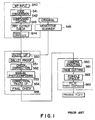
- FIG.1 is a flow chart showing a typical manufacturing process of a conventional print plate for printing, which comprises steps of inputting code data (Step S40) prepared by a word processor and the like, checking a PPC output after a code conversion (Step S41) of the code as prepared and a composing editing (Step S42), and outputting characters from a computer aided photocomposer ( hereinafter referred to as " photocomposer " ) (Steps S43 and S44).
- the composing editing is meant to refer to arrangement of a row of the characters according to a prescribed rule, more specifically a forbidden processing or the like.
- the word processor used for an office automation or the like is designed so that full scale characters are disposed in order.
- the art of photo-composing is contemplated to obtain the well aesthetical characters each of which is a hall of the width of the full scale character.
- the PPC output is a synonym for a laser beam printer (LBP).
- LBP laser beam printer
- the output of the high quality image output unit is a black-and-white sensitized paper or film either of which is silver halide and expensive but functions at a speed lower than the LBP due to high resolving power.
- the LBP is of less revolving power because of an electrophotographic system and is thus inexpensive but acts at a high speed. For this reason, the LBP is sufficient for checking and correcting layouts, characters or the like.
- the PPC output is also meant to refer to confirmation of the characters or the like prior to the high quality image output without trial.
- the original for designs or the like is read out by a monotone scanner such as to output the image as screen dotted (Step S45).
- Computer aided and manual photocomposer character outputs, a line image, and an illustration and the like as well as such the screen dotted output are manually paste up (Step S50).
- a galley proof of its synthetic image is obtained to check its content and to correct it if necessary (Steps S51 and S52).
- the manual photocomposer output for paste-up is provided to finally check and correct the image (Steps S54 and S55).
- Step S60 a camera work
- Step S61 a page cutting
- Step S62 a pinhole opaque
- Step S63 a film photo-composing
- the conventional plate making process requires a great deal of operations such as repeated paste-up, photocomposing to involve much labor and time, thus considerably decreasing efficiency.
- sampling methods for data For example, there has been proposed a sampling method comprising steps of reading picture images by a reading means to obtain image data of n bit/pixel, sampling the data or the density data while writing them in a buffer memory such as a disc or an RAM as picture image data, processing the written data in accordance with the density, resolution and/or tone of an output unit or a display unit, and outputting them to a printer or the display unit.
- the conventional sampling method is inconvenient as it takes a long time in processing because the density data in n bit/pixel are written in the memory while sampling them simultaneously, and the amount of written data becomes enormous (e.g. in the case of data for the A4 size print-ready copy of 1000 dot/inch, the amount of data reaches as large as 120 Mbytes ). If the data should be displayed, the processing such as thinning becomes necessary, and a large volume of data which are not essentially necessary have to be read out in a buffer.
- Discs of the filing capacity of 300 Mbytes - 3 Gbytes are usually used when picture images are written in as data.
- the sampling pitch or the number of tones in A/D conversion of the data should be adjusted in accordance with the output unit, and the picture image data for one output are saved by one scanning in a writing-in unit.
- the output unit In order to newly prepare data for display purpose, the output unit should be scanned once more, requiring an additional time further.
- This invention is provided in view of the aforementioned circumstances.
- an image processing system com strictlyprising an input controller having a first CPU adapted to dot and compress density data for an image read out by an input unit and for temporarily staying said compressed image data at a buffer; a work station providing a second CPU adapted to picture-edit not only a code information edited by an editing input unit but also said image data by the use of an input operating means and a display means; a file server including a third CPU connected to said input controller and said work station by bus lines and for storing said image data, code information and edited data picture-edited by said work station in said file server; and an image setter having a fourth CPU for reading out said edited data stored in said file server and subjecting said edited data to a required data processing, thereby outputting an image over an image output unit characterized in that said input controller, said file server, said work station and said image setter are individually and independently subjected to an information processing.
- an image processing apparatus comprising a CPU having a main memory connected to a CPU bus and interfaces, a sequencer connected between said CPU bus and an image data bus for transferring image data, a logical operational circuit connected between said CPU bus and said image data bus, a common memory connected between said CPU bus and said image data bus, an expander and a third memory connected from said CPU bus to said image data bus, a raster image converter and a second memory connected from said CPU bus to said image data bus, a vector font memory which stores vector fonts necessary for generating character bit map by said raster image converter and is connected to said CPU bus, and an output circuit which is connected between said CPU bus and said image data bus via a buffer and is connected to image recording devices via a buffer.
- a sampling method for data comprising the steps of digitizing predetermined data by an A/D converting means,inputting thus digitized data into plural thinning means, sampling said data based on respective table data which have been inputted into said plural thinning means to prepare plural sampling data, inputting said sampled data into plural data converting means and storing this converted data in a buffer.
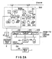
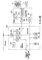
- FIGs.2A and 2B are block diagrams showing the whole arrangement of a system according to this invention.
- An input unit 1 (such as a scanner or the like ) is adapted to read originals such as designs, characters, patterns and the like.
- Density data (or tone data) DD of the image as obtained by the input unit 1 are inputted to an input controller 100.
- the input controller 100 dots the aforementioned inputted density data DD through an incorporated CPU 101 by means of a halftoning circuit 102 and is then compressed by a compression circuit 103.
- the data is temporarily stored in a buffer 104 and transferred for storing it in a magnetic tape 210 of a file server 200 or hard discs 220, 221, ⁇ ⁇ thereof.
- the input controller 100 includes a local disc ( hard disc ) 105 for temporarily storing the data.
- the filer server 200 is provided with a CPU 201 and connected to another apparatus by interfaces 202 to 205.
- a code information CD such as characters and the like which is obtained by an edition input unit 2 such as a word processor and a composing machine is once stored in a floppy disc 3 and then read out.
- the code information CD is then inputted to a work station 300. This input may be inputted in on-line.
- the work station 300 carries a plurality of terminal units each having a CRT 301 as a display means, a keyboard 302 as an input operative means, a mouse 306, a digitizer 303, a hard disc 304 as a memory means, and a floppy disc 305.
- the work station 300 is interconnected by an Ethernet ( one type of bus line systems ) to the file server 200 compressed image data and contour display image data ( as will be described later ) obtained by the input controller 100, which are thinned ( selected ) for CRT display are stored in the magnetic tape 210 or the hard discs 220, 221, ⁇ ⁇ . These two data are transferred by interfaces 204, 202 read out through an SCSI bus to the work station 300.
- a control command and the like between the work station 300 and the input controller 100 are transferred through the interface 203 of the file server 200 to which an image setter 400 is connected.
- the image setter 400 is formed with a CPU 401 which is connected by an interface 402 to an auxiliary data line 5 of the file server 200 and is coupled by an interface 403 to the SCSI bus.
- the image setter 400 further includes a sequencer 410 and a buffer 411 for storing a required data.
- a high quality image output unit 10 for outputting the image of high quality image and a laser beam printer 11 for inputting the image of relatively low quality image are connected to the image setter 400.
- the hard disc 220, 221, ⁇ ⁇ are adapted to previously store not only fixed data ( but map data ) such as a logo, a crest and the like but also a vector font data for outputting the character.
- the input unit 1 is adapted to digitize all of the design ( gray scale image or half-tone image ), line image, and the character image ( binary image ) by means of density data (8 bit/picture element).
- a signal inputted based on 9 bit/picture element causes the design to be dotted by the input controller 100 so that an information ( 4 bit/picture element ) may be provided.
- the binary image is converted to an information ( 1 bit/picture element ).
- These 4 bits/picture element and 1 bit/picture element are compressed for use in the LBP 11 and the high quality image output unit 10.
- the data for CRT display and contour display are thinned.
- the character is inputted by a code from the work station 300, it may be inputted in an image form from the input unit 1.
- the image is outputted independently by the image setter 400.
- the image setter 400 is intended to convert all of code and vector informations to the bit map data so that the image output as referred to herein is used to mean the output of the bit map data.
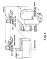
- FIG.3 is a schematic view showing the outlay of the system according to this invention.
- the system main body incorporated the input controller 100, the filer server 200, and the image setter 400 and includes the input unit 1 and a plurality of the work stations 300 connected thereto so that the processed image may be outputted from the high quality image output unit 10 or the laser beam printer 11.
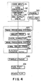
- FIG.4 is a flow chart showing the sequence of the steps of the image processing system according to this invention.
- a code information CS prepared by the edition input unit 2 is inputted through the floppy disc 3 to the work station 300 (Step S1)
- a required code conversion is made (Step S2).
- a composing editing (Step S3) is effected by given operations of a keyboard 302, a mouse 306, and a digitizer 303.
- a PPC output image is checked (Step S4) against the editing data obtained through the aforementioned steps to transfer the data to the image processing system (Step S20).
- the data which are subjected to the steps such as S1, S2, S3 and S4 may be inputted by the floppy disc 3 to the image processing system.
- the originals such as the design, character or the like are read out by the input unit 1 (Steps S10 and S22).
- the read data are then inputted to the image processing system (Step S20).
- the code information CD and the density data DD inputted to the image processing system are subjected to processed (as will be described later) by the input controller 100, the file server 200, the work station 300, and the image setter 400 are then outputted (Step S21) as a galley proof by the laser beam printer 11.
- These information and data are checked by the human eye and subjected to a data correction (Step S22) by the use of the work station 300.
- the corrected data are transferred to the magnetic tape 210 or the hard discs 220, 221, ⁇ ⁇ and are stored thereon (Step S23).
- the final galley proof is outputted (Step S24) with respect to the stored and corrected data.
- an electronic pagenation output (Step S25) is outputted to the high quality image output unit 10 to then subject the galley proof to a pinhole opaque (Step S30), thereby applying a plate photo-composing, for instance, a four photo-composing of A4 size to obtain a print film, photo-sensitive paper and a print photo (Step S31).
- the image processing system in accordance with the invention requires neither manual paste-up of drawings and photographs nor manual photo-composing to facilitate reduction of labor and material.
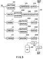
- the input controller 100 is adapted to creatively process the density data DD inputted from the input unit 1 simultaneously with five sets of data which consist of high density data for the high quality image output unit 10, data for the laser beam printer 11, two types of data for displaying the CRT 301 of the work station 300, and pattern data made rough enough to show the contour.
- the data are subjected to such simultaneous processing in overlap manner to accelerate the speed so that the data forming operation load of the CPU 101 may be reduced by a hardware.
- the high density data for the high quality image output unit 10 is dotted by a halftoning circuit 1021 and data-compressed by a compression circuit 1031, the compressed data being held in a buffer 1041.
- Data used for allowing the laser beam printer 11 of relatively low quality image to output the image are subjected to the density data DD which are thinned (110) at a predetermined distance (for instance 1/3 ).
- the rough data are dotted by another halftoning circuit 1022 and compressed by another compression circuit 1032 and then temporarily heldin another buffer 1042.
- Two types of rougher data for CRT 301 display are caused to thin the density data DD at a predetermined distance and are then dotted by different halftoning circuits 1023, 1024 and then temporarily held indifferent buffers 1043, 1044.
- the image data after Laplacian or unsharp mask processing for showing contour data are thinned and then binarized by a binary circuit 1025 and also temporarily stored in a buffer 1045.
- the Laplacian or unsharp mask processing is effected ahead of the input unit 1 or before thinning processing (113).
- the image is thinned at a selection rate by which the inputted image zone may be displayed at its maximum and at another selection rate by which the image is displayed in the form of a one page layout whereas contoure data is thinned at a selection rate of 1/2 when it is CRT displayed with accuracy one half of picture element density of the high quality image output unit 10.
- buffers 1041 to 1045 are connected to an inner bus 122 and by an interface 121 to an SCSI bus, and that the half-toning circuits 1022, 1023 and 1024 functions as binarization.
- a local disc 105 is connected by an interface 120 to the inner bus 122.
- the CPU 101 communicates with the input unit 1 by a data line (not shown) and also communicates through an auxiliary data line 4 and a dual port RAM (not shown) to the filer server 200.
- the CPU 101 is caused to set the data required for the respective circuits as shown in FIG. 5.
- the set data are stored in the local disc 105 while a set point in association with sub-scanning is set.
- the density data DD from the input unit 1 are inputted every one line and stored in the buffers 104 ( 1041 to 1045 ) upon synchronization of the respective circuits shown in FIG.5.
- the CPU 101 checks not only a changeover of the SCSI bus and of a data compressing output buffer 1041 but also a presence of error information from the respective circuits.
- the once stored in the buffer 104 and the local disc 105 are stored by the command of the CPU 101 and outputted to the SCSI bus from without.
- the input controller 100 communicates with the filer server 200 when the data are employed in on-line, resulting in provision of an address on the SCSI bus a whereas the input controller 100 establishes a file control of the magnetic tape 210 when the data are used in off-line ( input controller 100 solely ).
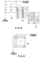
- FIG.6 shows a manner in which dotted data DT are obtained by the density data DD and a threshold matrix 120.
- the binary dotted data DD of 4 bits per one picture element are formed by comparing four thresholds per one picture element to density level values "0" ⁇ "255" ( 8 bits ) of the inputted density data. If the level value of the inputted density data DD is higher or lower than the threshold of each bit of the threshold matrix 120, the dotted data are represnetative of "1" ( black ) or "0" ( white ).
- the each bit threshold of the threshold matrix 120 is independent of the level value of the picture element but solely depends on the coordinates of the picture element.
- the size of coded block BL twice the dotting threshold data DT1 that is, two dotted units so that a coded system by which one picture element is put as 4 bits as indicated at PL may be employed ( dotted image to which 150 lines and 45° are plotted ).
- the size of the coded clock BL is the two dotted unit to obtain the image of 100 picture element/block.
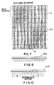
- the density data DD is binarized by the threshold matrix 120 every block as shown in FIG.8 to obtain dotted data DT2 as seen from FIG.9.
- the desnity data (4 bits) dotted in the block BL are rearranged in the order of value of the four thresholds every picture element of the threshold matrix 120. Rearrangement of these data are made in the order of fixed value as determined by the threshold matrix 120. More specifically, the threshold every bit of the threshold matrix 120 is fixed as shown in FIG.7 so that the image data as well as the bit data of each picture element may be rearranged in the order of value of the threshold, thereby establishing rearrangement of all the density data in the order of value of the threshold as shown in FIG.10.
- the rearranged dotted data DT3 of 400 bits are coded every 8 bits in such a manner that they are scanned in 8 bits from the beginning to obtain the number of units in 8 bits followed by "0" as well as 8 bits.
- This group is termed white section W of length "0" ⁇ "50” and is thus coded by 6 bits.
- the rearranged dotted data DT3 of 400 bits are scanned in 8 bits from the rearmost end to obtain the number of units in 8 bits followed by "1" as well as 8 bits.
- This second group is termed block section B of length "0" ⁇ "50” and is thus coded by 6 bits.
- Intermediate data other than black and white sections W, B of the rearranged dotted data DD3 of 400 bits are termed intermediate data.
- These intermediate data are provided with only 25 types of patterns as illustrated from a code table 0 ⁇ 3 of FIG.11 as a result of the aforementioned rearrangement as viewed from a unit of 8 bits. These data are all coded fixedly by a coded code of 5 bits. Stated otherwise, the intermediate data of 8 bits may be compressed into the data of 5 bits.
- the number l of the picture elements is put as an integer and coded to be (n+1) l types of patterns when such coding is made in l ⁇ n ( number of dotted data per picture element ) to substitute 2 x-1 ⁇ ( n + 1) l ⁇ 2 x of X bits.
- the file server 200 is fablicated in the manner as shown in FIG.2 and functions common file controls such as a file control and community of file, and control of network communication and communication between units. More specifically, the file server 200 passes through the SCSI bus to control the file for the hard discs 220, 221, ⁇ ⁇ , and the magnetic tape 210 and is caused through the Ethernet to provide function as a software interface for the work station 300.
- the file server 200 fulfills an utility function with respect to service for a file control information on the input controller 100 and the image setter 400 and with respect to a file control via the SCSI bus.
- Such utility functions are, for instance, a registration of font and a gerbage collection ( dust pick-up and disposal ).
- the registration of font may be classified into two types of registration.
- the first type of the font registration is supported by a system, wherein a vector font prepared by a different font preparation system is stored as a magnetic tape form in the hard disc of the image processing system.
- Another type of the font registration is a registration of external characters which do not exist in the system. In this instance, the font prepared by another system is registered in the floppy or magnetic tape.
- the character image may be read out by the input unit to regist raster data after vector processing.
- the reason why the garbage collection is made is as follows.
- the instant image processing system requires for the hard discs 220, 221, ⁇ in the file server 200 to erase the prepared files many times. Accordingly, the effective available zone in the hard discs present vermiculated spots.
- the file server 200 is adapted to perform service and store the data for transferring the data between the work station 300 and the input controller 100 and between the latter and the image setter 400.
- the input controller 100 serves to obtain required information from the auxiliary data line 4 and the dual port RAM.
- the data which is once held in the buffer 104 wherein the input controller as the file for the image processing system, informations on the file name, file capacity and the like are transferred to the file server 200 to allow the hard discs 220, 221, ⁇ ⁇ on the SCSI bus access thereto. This will enable the file server 200 to communicate with a directory and to control a disc area and the like.
- the file server 200 is also adapted to transfer the file data by the Ethernet to the work station 300 and receive the data from the work station.
- the file server 200 controls the hard discs 220, 221 ⁇ ⁇ on the SCSI bus and the magnetic tape 210 under the command of the work station 300 to renew information required for the directory and the like.
- the file server obtains the command over the image setter 400 and the other command over the magnetic tape, thereby performing service according to those commands.
- a predetermined command is issued by the auxiliary data line 5 and the dual port RAM to the image setter 400 whereas the file control information is sent upon request from the image setter 400 to allow the latter access to the disc data on the SCSI bus.
- the utility information as to the image processing system as a whole is controlled by the hard discs 220, 221, ⁇ ⁇ on the SCSI bus and subjected to font information and common files and the like in the system.
- an IBM-AT Ethernet board is used to facilitate a support ( TCP/IP protocol ) for the Ethernet.
- a fundamental configuration for driving such Ethernet board is similar to that of the IBM-AT and is actuated on an MS-DOS to reading realize the TCP/IP protocol.
- the protocol is meant to refer to a communication rule established between hosts for communicating.
- a seven layer OSI ( International Organization for Standardization ) model has been suggested by the OSI.
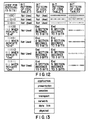
- the seven protocol layers range from a Physical Layer to an Application Layer as shown in FIG. 13, depending upon abstractness of communication. For instance, the Physical Layer carried out a rule of "0", "1" according to voltage level whereas a data link layer follows a rule of data transfer in a lamp and error detection.
- a network layer includes a communication rule for determining a destination of the data in a packet and an indication of the sequence of the packet.
- the TCP/IP protocol is a communication rule which is corresponding to a transport layer and established between the hosts.
- the TCP/IP protocol is capable of establishment of connection with a mating host, transfer of buffer data between the hosts, and establishment of multi-connection with a plurality of the hosts.
- the Ethernet board is a type of an extended board of a personal computer, which incorporates, the CPU for communication, by the Ethernet.
- the IBM-AT Ethernet board is a type of a board which is corresponding to a CPU bus and an extended slot of the IBM-AT personal computer to support a protocol layer laid downwardly of the TCP/IP protocol ( OSC model transport layer of the ISO ).
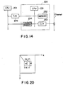
- a CPU 201 of the IBM-AT and a CPU 231 of the Ethernet are adapted to send and receive the data with a common memory 234 in an I/O port 206 and the Ethernet board.
- the MS-DOS is an operating system which establishes control of input and output of the disc, memory control, process control and network control, and performs function of machine interface and the like.
- FIGs.15A and 15B show a manner in which communication is held between the file server 200 and the input controller 100 and between the file server 200 and the image setter 400. More specifically, if a writing request on a subject image data is made from the input controller 100 to the file server 200, the file server 200 transfers data writing permission and writing address for writing the data to the input controller 100 (Step S201). In this instance, when the file names are identical with each other and the hard disc is running at full capacity and so on, the data writing permission is not obtained.
- the input controller 100 is caused to write the image data ( compressed density data ) via the SCSI bus on the assigned address of the hard discs 220, 221, ⁇ ⁇ or the magnetic tape 210 (Step S202).
- the data if read in the magnetic tape 210 or the hard discs 220, 221 ⁇ ⁇ to transfer the data to the image setter 400 make writing request for the data, the subject from the image setter 400 to the file server 200 (Step S210), thereby transferring data reading out permission and reading out address of the date to be read to the image setter (Step S211).
- the file server 200 is then allowed to read out the data of the assigned address via the SCSI bus and transfers the data to the image setter (Step S212).
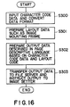
- FIG.16 is a flow chart showing how the work station 300 function.
- the work station 300 is actuated to input character code data so that a data format may be converted (Step S300) to interactively or batch-processingly prepare layout data such as an image mounting frame and the like (Step S301).
- layout data such as an image mounting frame and the like
- Step S302 output data described in page descriptive languages are prepared based on these character code data and layout codes (Step S302), and are transferred to the file server 200 to instruct the output to the image setter 400 via the file server 200(Step S303).
- FIG.17 is also a flow chart showing how the work station functions at full length.
- Document data edited and stored by the edition input unit 2 is read out of the floppy disc 3 (Step S310).
- a code information CD of the document data is subjected to conversion of the data format (Step S311).
- a content of the document in one page is then displayed in the CRT 301 (Step S312) while an image data output position is instructed by the mouse 306, the keyboard 302 and the digitizer 303 (Step S313) to prepare page description data every one page (Step S314).
- Step S315 the data are prepared in full pages (Step S315), and photo-composing for preparing a printing block copy is instructed by the keyboard 302 (Step S316) to obtain photo-composed page description data (Step S317).
- the prepared data are transferred to the file server 300 (Step S318) simultaneously with instructing the image output to the image setter 400 for completing the operation (Step S319).
- the format pattern may be modified with the aid of the format registration sheet utilizing the keyboard 302.
- the editing work is effected by following such steps as initiation of the operation, preparation of operation, input and conversion of composition data, output of galley and/or block copy, and completion of the editing operation.
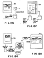
- the document number and job number are sequentially designated with the aid of such a work indication sheet displayed on the CRT as shown in FIG.18C, and then the initiation of the editing work is performed with the mouse 306.
- the mouse 306 is used to indicate, as working conditions, display of image, output of galley output of block copy, and addition or alteration of image.
- character orlayout data floppy disc 305
- various kinds of image data the hard discs 220, 221, ⁇ of the file server 200 or the magnetic tape 210 are loaded in the hard disc 304, as shown in FIG.18D.
- the series of the above processing is started as a background job and is processed in an overlapping manner, and a layout scope for editing work is displayed upon completion of data loading.
- the indication of a new input ( or replacemen ) or additional input is, as shown in FIG.18E, made in regard to what is to be inputted with the aid of a composition data input sheet on the display, and then the floppy disc 3 is set in a given position, and composition data are inputted to be stored in the hard disc 304.
- the data conversion is automatically effected, and the composition data input processing is started as a background job and is performed in parallel with other data processing.
- the page to be editted is designated, and the contents thereof are then displayed. After a frame is designated, designation of the line(s), graph(s) and tint is also made.
- the number of pages to be edited is directly or indirectly (next, previous) designated using the layout scope, and in a case where the page to be edited is already present, the character and layout are displaced on the CRT 301 in the form of WYSIWYG (which stands for " What You See Is What You Get " and means that you can obtain a hard copy of what is displayed on the CRT 301 ).
- An area in which images are displayed is called a frame, and this frame is configured by means of the pointing of the mouse 306 or of the operation the keyboard 302 selecting a number of commands displayed on the CRT 301 and then displaying input on the CRT 301 in the form of WYSIWYG.
- the image number to be put in the frame is designated by means of the keyboard 302, and the image data stored in the hard disc 220, ⁇ is displayed on the CRT 301 by giving a re-display command and the like.
- rules, enclosing rules, tint and the like are formed by means of the mouse 306 or the keyboard 302 selecting the numbers of various kinds of commands displayed on the CRT 301 and displaying them on the CRT 301 in the form of WYSIWYG.
- the designation of the page to be outputted, the number of copies to be made and the like is effected with the aid of a galley or a block copy output sheet as shown in FIG.18G, indication of the required output thus being effected.
- the editing data ( character data and layout data ) are automatically converted to the output data, which are then stored in the hard discs 220, 221, ⁇ , and then stored output data are outputted from the high quality image output machine 10 or the laser beam printer 11 via the image setter 400.
- this output processing is started as a background job, and a plurality of requests for output therefrom are put in the output queue of the image setter 400.
- the output queue is used to keep the requests waiting in order for processing.
- the indication of preservation forms for the character, the layout and image data are effected with the aid of a data preservation sheet which is displayed on the CRT 301 when the preservation and the completion is indicated, and in accordance with the preservation forms so indicated as shown in FIGs.18H and 18I, the character and layout data, and various image data are, respectively, stored in the floppy disc 305 and the hard discs 220, 221, ⁇ of the file server 200 or the magnetic tape 210.
- indication of the editing work is effected with the aid of the work indication sheet, every processing is terminated, with the processing queue being left as they are, and finally the power supply is cut off.
- Step S330 The image data in the hard discs 220, 221, ⁇ of the file server 200 are loaded in the work station 300 (Step S330), and the document data in the floppy disc 3 are also loaded in the work station 300 (Step S311). Then, the necessary information is displayed on the CRT 301 of the work station 300, thus making it possible to suitably layout the images and documents, by page by page, by operating the mouse 306, the keyboard 302 and the digitizer 303 (Step S332).
- each page is displayed on the CRT 301 as being laid out in the indicated photo-composed state (for instance, "A" to "D” as shown in FIG.19), with a suitable page number being given thereon (Step S334).
- the photo-composing state of each page is registered and stored with a proper page number being given thereon in advance with consideration given to the process of folding a plurality of pages in book binding, and, for instance, takes the form of four pages of paper of a trimmed size of A4, or eight pages of paper of a trimmed size of A5.
- the photo-composing state so selected is displayed with the proper page numbers being given to the associated pages (for instance, "1", “8", "5", "4", in figure B ), as "A” to "D” shown in FIG.19.
- the display of layout on the CRT 301 on this occasion is designed to show only the photo-composing states of the pages, and the contents of the pages such as the images and characters thereon are not displayed, bit maps which will be explained hereinafter being generated by the image setter 400 in accordance with the page description data and then outputted (Step S335).
- the page description data are the form of indication used to indicate the character output, graph drawing and image output.
- the character output it is possible to print an arbitrary character of an arbitrary size at an arbitrary position ( a position of two dimensions ), the character also being able to be rotated and tilted at arbitrary angles, and shortened horizontally and vertically at arbitrary rates.
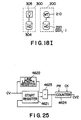
- FIG.20 is a diagram showing the character " A " having a width W and a height H which is located at the position ( X,Y ) on the xy-coordinates and rotated through 90 degrees thereat.
- the graph drawing it is possible to give indications to such factors as drawing rules of arbitrary size and length, drawing circles, arcs and ellipses and the tint processing within the area.
- the image output it is possible to give indications to output the image data which are inputted by means of the input controller 100 and kept in the hard disc (220, ⁇ ) at arbitrary positions with arbitrary trimming effected thereon.
- the characters, the graphs and the images can be disposed at arbitrary positions by utilizing these three types of indication commands.
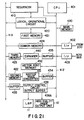
- FIG.21 shows in detail an example of the configurations of the image setter 400.
- the CPU 412 and an image data bus 413 are connected to the sequencer 410, and a logical operational circuit 240 and a first memory 421 are also connected to the same sequencer 410.
- a main memory 430 for the CPU 401 is connected to the CPU bus 412, and a common memory 424 is disposed between the two buses 412 and 413 so as to connect the former to the latter, the output from the interfaces 402 and 403 being inputted into the CPU bus 412.
- a buffer 433, an expander 440 and a third memory 423 are connected to each other in that order between the CPU bus 412 and the image data bus 413, and a buffer 434, a raster image converter 431 and a second memory 422 are also connected to each other in that order between the same buses 412 and 413.
- a buffer 435 and an output control circuit 436 are also connected to each other between the buses 413 and 412.
- a vector font memory 432 is connected to the CPU bus 412, and the high quality image output unit 10 and the laser beam printer 11 are respectively connected to the output control circuit 436 via an output buffer 436A.
- Vector fonts are stored in the vector font memory 432 which are needed at the time character maps are generated by the raster image converter 431.
- a character bit is generated under the following processes of:
- FIG.22 The operation of the image setter 400 which is configured as described above is shown in FIG.22.
- a request for output indication is outputted from the file server 200 to the image setter 400 by using a file name stored in the hard discs 220, 221, ⁇ as a parameter.
- the specification to be outputted is written in the file. While sequentially decoding this specification, address computation of coded data and compressed data is performed relative to every image unit, and the overlapping processing by the logical operation is repeated relative to the address, the results of the processing then being stored in the first memory 421. Calling the parameter file via the SCSI bus, the image setter 400 repeats this operation.
- the character code and such indicating information as position, type face, size and the like are inputted via the SCSI interface 403 (Step S400), and the raster image conversion of what is inputted is effected via the raster image converter 431 (Step S401), the raster image data then being stored in the second memory 422 (Step S402).
- the data-compressed image data are sent by way of the SCSI bus and are inputted via the interface 403 (Step S403), and the data are sent by way of the buffer 433 and are expanded by an expander 440 to be reproduced (Step S404), the reproduced image data then being stored in the third memory 423 (Step S405).
- bit map data such as logotypes and the like which are stored in the hard discs 220, 221, ⁇ are inputted via the interface 403 (Step S406) and are stored in the common memory 424 (Step S407). All data stored in the second memory 422 through the common memory 424 are the bit map data, and the logical operation of these stored data is performed via the CPU 401 (Step S410), the data which are so logically operated as to synthesize, edit or image-process pictures, documents or the like are stored in the first memory 421 (Step S411).
- Step S412 judgement of whether the editing work is to be completed or not, in other words, whether or not there will be further additions or modifications to be made, is made (Step S412), and this operation of judgement conditions until logical operation of modification or the like has been completed.
- This logical operational circuit 420 effects in coorperation with the CPU 401 logical operation of the bit map data generated from coded data, i.e. characters or the like, bit map data obtained by expanding the compressed image data and the "sum”, "product”, “difference”, “exclusive or” and the like of the bit maps, and generates image information to be outputted via the output unit 10 or the laser beam printer 11.
- the CPU 401 is designed to input information regarding the layout indication from the hard discs 220, 221, ⁇ ⁇ , and to pass information regarding setting the transfer area to the second memory 422 through the common memory 424 as well as to transmit timing signals to the raster image converter 431 and the expander 440.
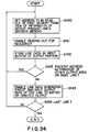
- FIG.23 shows in more detail the circuit configuration of the logical operational circuit 420, and an example of the operation thereof will be explained with reference to FIG.24.
- the data transferred via the CPU bus 412 are inputted into a mode register 451, a constant register 454, preset counters 460 and 462 and an address counter 463.
- the output from the mode register 451 is inputted into a bit controller 452, which is designed to enable a barrel shifter 457 for performing high-speed shift.
- the output from the address counter 463 in inputted into a multiplexer 464.
- the output from the bit controller 452 is inputted into a mask pattern gate 453 for outputting regular-shaped data, and the output from the mask pattern gate 453 is inputted into a multiplexer 459 as well as a comparator 461.
- the constant data from the constant register 454 is inputted into a multiplexer 455.
- the data FD read out of the first memory 421 is transferred to an operation bus as well as the multiplexer 455, and the output MX1 from the multiplexer 455 is, together with the output data BD from the barrel shifter 457, inputted into an operation circuit 458.
- the operated output AL from the operation circuit 458 is inputted into the multiplexer 459, and the output MX2 therefrom is inputted into the first memory 421 to be stored therein.
- the multiplexer 459 writes them and uses bits needed to effect writing after generating bit patterns by means of mask patterns.
- the data transferred from the image bus 413 is inputted into the barrel shifter 457 after the LSB and MSB thereof are inverted at a bit inversion circuit 456 depending upon necessity (for instance, in the case of an inverted display due to multiplication ), and the output MX3 from the multiplexer 464 is inputted into the first memory 421 as an address command and is stored therein.
- the preset counters 460 and 462 count the clock pulse CK and are designed to cause the comparator 461 to output a count-preset-enable signal PR when the preset counter 460 counts up to a given value (for instance, the preset value or "0" ), the count-preset-enable signal being already in the preset counters 460 and 462.
- the preset counter 462 comprises a start register 4621, a line length register 4622 for setting line length data, an adder 4623 for adding the respective values of the start register 4621 and the line length register 4622, and a counter 4624.
- Access to the memory is normally effected every 16 bits as a unit. However, since the present invention uses the bit map data, if data are written every 16 bits, the data will be written at improper bit positions. In addition, in a case where the address position of a source is different from that of a destination, it is impossible to write data at proper positions unless bit positions are shifted.
- the barrel shifter 457 is used for this purpose.
- storing data in the first memory 421 is effected by storing the results of operation in a designated address using the output MX3 from the multiplexer 464 as address data.
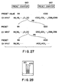
- the preset data from the CPU bus 412 are inputted into the preset counters 460 and 462, and in a case where the relationship between the output line and effective data resembles one shown in FIG.26D, the preset counters 460 and 462 are, as shown in FIG.27, preset at "99" and "1000", respectively.
- the preset counter 460 counts the clock pulse CK in a count-down manner, while the preset counter 462 counts the clock pulse CK in a count-up manner.
- the comparator 461 When the preset counter 460 counts to "0", the comparator 461 is designed to output a count-up signal CR, and the preset counter 460 is preset against “99", while the preset counter 462 is preset at "1200", similar operations being repeated thereafter.
- the start register 4621 when an image shown as an area 470 in FIG.28 is written in the first memory 421, the start register 4621 is first initialized at "-200 which is the value indicating the data position of a point 471", with the line length register 4622 being set at "200”.
- the preset counter 460 is preset at "100", and the preset counter 462 is preset at "1400", and the clock pulse CK is inputted.
- the comparator 461 When the clock pulse CK is counted up to "100", the comparator 461 outputs the count-up signal CR, and the counter 4624 is set at the value representing the point 461, in other words, at "+200" which represents the head address one line before.
- the clock pulse CK is inputted, and operations similar to this are repeated thereafter.
- the output from the preset counter 462 is selected by the multiplexer 464 and is inputted into the first memory 421 as the address data MX3.
- the data FD read out of the first memory 421 by means of this address are inputted into the multiplexer 455, and the multiplexer 455 outputs either the data FD or the constant data CD from the constant register 454.
- the output MX1 from the multiplexer 455 is inputted into the operation circuit 458.
- the data transferred from the operation bus via the bit inversion circuit 456 and the barrel shifter 457 are already in this operation circuit 458, and the operated data AL of the operation circuit 458 are inputted into the multiplexer 459.
- the pattern data PD from the mask pattern gate 453 are already in the multiplexer 459, and either of these data are selected for output therefrom as the output data MX2, which are stored in the first memory 421. This type of operation of data and storage of data in the first memory is effected word by word.
- the initial value passed from the CPU bus 412 every line is set in the address counter 463, and address renewal is effected by means of a clock, and the output values are selected by the multiplexer 464 for effecting addressing.
- the data designated by the address of the output MX3 from the multiplexer 464 are read out of the first memory 421 for transfer to the operation bus.
- the sequencer 410 is set at the address to be read out of the first memory 421 after viewing the information (this information is created by the CPU 401 and is passed in advance to the output control circuit 436 via the CPU bus 412 to be stored therein ) of an output-preset-area address memory in the output control circuit 436 (Step S420) and is then enabled for reading-out operation for the sequencer 410 (Step S421). Subsequently, the data on the relevant line is stored in the input buffer 435 of the output portion (Step S422), and judgement is made as to whether or not the address information belonging to other output areas is present on the same line (Step S423).
- a line data generation circuit inside the output control circuit 436 is enabled to input into the output buffer 436A the output data corresponding to the quantity of one line (Step S424), this operation being repeated until processing of the last of the lines is completed.
- Each unit of the image setter 400 is started in a parallel or sequential manner by means of the CPU 401, and this results in the fact that access to the first memory 421, output of data from the output control circuit 436, conversion of raster images and the like are effected in a time-sharing manner.
- the output-presetn-area memory only stores data like one representing the area 470 shown in FIG.28, and a blank area surrounding such an image area acts as a white or black area for interpolating the data.
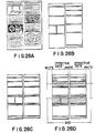
- FIG.26A shows a document containing information equivalent in quantity to that to be outputted as one page.
- FIG.26B shows bit map data needed to output the information shown in FIG.26A, wherein the respective rectangles represent bit map data secured in the memory area ( the first memory 421 ).
- a bit map corresponding to one rectangle corresponds to the continuous memory area, but no relationship in terms of memory is present in the portions of the memory area which correspond to gaps formed between the respective ractangles.
- FIG.26C shows the bit map area which is separated in the transverse direction (block separation) in order to produce the output-present-area address, and this causes all lines in one block to have the same effective data position and length.
- FIG.26D shows, respectively, portions necessary (effective data) and portion unnecessary (white data) to be read out of the first memory 421 by means of the sequencer 410 when the output data corresponding to a quantity of one line is inputted into the output buffer 436A in the output control circuit 436 or is directly outputted therefrom.
- the data are read out of the first memory 421.
- FIG.29 shows a block diagram of a structure of the data sampling unit embodying this invention data sampling method.
- picture images 500 for printing are read out optically by a scanner 501 to be sampled before the data are outputted.
- the density data of the picture images 500 which are optically read out by the scanner 501 are inputted into an A/D converter 502 to be converted into digital density data AD, which in turn are respectively inputted into thinning means 506 through 508.
- the thinning means 506 through 508 thin the density data AD based on the table data TD1 through TD3 which are inputted from sampling tables 503 through 505 for sampling purpose.
- FIG.30 shows the density data for one page BL wherein main scanning line data are indicated horizontally while the auxiliary scanning line data are indicated vertically.
- the sampling data MD for one page BL are prepared in this method by thinning the main scanning lines A0 through A n at timings of A0, A2, A4, ⁇ ⁇ , A n and at the same time, the auxiliary scanning lines B0 through B1 at timings, for example, of B0, B2, B4, ⁇ ⁇ , B n as shown in FIG.31.
- the timings to this out the density data AD in the main scanning line and the auxiliary scanning line for one page BL at the same ratio as described above are stored in advance as table data TD1 through TD3 so that the sampling may be conducted by thinning the density data AD based on the table data TD1 through TD3.
- the table data TD1 samples the density data AD in accordance with the dot density compatible with the resolution of the display unit such as a CRT, to convert them into the data which have the tone and resolution identical to those of the display unit.
- the table data TD2 samples the density data AD in accordance with the dot density compatible with the second printer to convert them into data which have the tone and resolution identical to those of the second printer.
- the table data TD3 samples the density data AD in accordance with the dot density compatible with the first printer ( or the finishing printer ) to convert them into data which have the tone and resolution identical to those of the first printer.
- the sampling data MD1 through MD3 which have been sampled as above by the thinning means 506 through 508 are inputted into bit-byte converting means 509 through 511, and the data in byte BD1 through BD3 are written in temporarily in buffers 512 and 513.
- Above mentioned units are inputted with synchronous clocks KS from a driving section of the scanner 501 so as to be operated at the same cycle.
- the picture images 500 are read out by the scanner 501, and converted into digital density data AD by the A/D converter 502 at corresponding timings.
- the sampling data MD1 through MD3 are prepared by the thinning means 506 through 508 based on the table data TD1 through TD3 of the sampling tables 503 through 505.
- sampling data MD1 through MD3 are converted from bit data into byte data by the bit-byte converting means, and written in the buffers 512 and 513.
- the data having the tone and resolution of the display unit and of the second printer are outputted from the buffer 512 while the data having the tone and resolution of the first printer are outputted from the buffer 513.
- the data sampling unit accordint to this invention can be operated with buffers having smaller memory capacity as the density data are thinned out during sampling by the plural thinning means, and the sampled data are written in the buffers. Since the sampling processes are conducted in parallel, the time required for the whole process is shortened.
- the sampling data MD1 through MD3 are directly inputted into the bit-byte converting means 509 through 511
- means for converting picture images into dots or binary codes may be provided at the upstream of the bit-byte converting means 509 through 511 so that the sampling data MD1 through MD3 are converted into the dots or the binary codes and then inputted. This can reduce the amount of data remarkably.
- a compression means or a means to convert the data into binary codes may be provided so that the sampling data MD1 through MD3 or dot or binary data are compressed before inputted.
- the amount of data can be reduced to ca. one fiftieth in total.
- This invention method allows partial sampling for one page simply by connecting the sampling tables with an exterior circuit ( or an R/W circuit of EXCPU ) so that table values may be set from outside.
- intput/output processing as well as work station prcessing can be simultaneously operated by menas of communication utilizing LAN (Ethernet) and SCSI, thus making it possible to realize an efficient overlap processing.
- the quantity of memory to be stored and the data transfer time can respectively be reduced with the aid of data compression/expansion by simultaneously generating the input data files with a view to reducing the load for the CPU, whereby the transformation of the vector invformation into the bit maps, and image processing, processing and editing thereof can be eased by utilizing hardware.
- the quantity of data to be bandled is reduced by generating the output data representing the image processing, processing and eiditing of the output bit maps utilizing the precision of picture element of the CRT, not the precision in the number of picture elements of the output bit maps, thus makes it possible to realize high-speed data processing.
- the data which is being written in the buffer is the data which have already been sampled instead of the data which are being sampled.
- the capacity of the buffer therefore, can be much smaller than the one needed in the prior art. Since the sampling and other conversion processing can be conducted in parallel, the time required for the processing can be shortened remarkably. Further, as processing units are all driven by the same synchronous clocks, the data can be processed in real time.
Abstract
Description
- This invention relates to an image processing system which is adapted to electronically interactive-edit images such as characters, designs, and binary images to process and image-record the same as a block copy for printing, further relates to a sampling method for data which is improved in performance by sampling image data for printing ( density data ) in a shorter time and reducing the time required for post-processing.
- It has been heretofore desirable to provide an image processing system for typographers who require high quality printed matter in which characters, designs or the like are consolidated as a whole for editing the same. Notwithstanding, such system has not been proposed but is less capable and practical in use even if it is available.
- Particularly, among others, a desk top publishing art has been gradually realized in a manner of description such as a post script but is still less capable and efficient of an image art. Systems for the typographers have been of course, available but is insufficient in handling ( input, display, storage, processing, edition, and output and the like ) data in bulk and at a high speed. This is because that the characters and images to be synthetically processed are subjected to various approaches by a description language, and a central processing unit ( CPU; software ) to thus exhibit a poor performance.
- FIG.1 is a flow chart showing a typical manufacturing process of a conventional print plate for printing, which comprises steps of inputting code data (Step S40) prepared by a word processor and the like, checking a PPC output after a code conversion (Step S41) of the code as prepared and a composing editing (Step S42), and outputting characters from a computer aided photocomposer ( hereinafter referred to as " photocomposer " ) (Steps S43 and S44). What is termed the composing editing is meant to refer to arrangement of a row of the characters according to a prescribed rule, more specifically a forbidden processing or the like. In general, the word processor used for an office automation or the like is designed so that full scale characters are disposed in order. In constant, the art of photo-composing is contemplated to obtain the well aesthetical characters each of which is a hall of the width of the full scale character. In this connection, it should be noted that the PPC output is a synonym for a laser beam printer (LBP). Generally, the output of the high quality image output unit is a black-and-white sensitized paper or film either of which is silver halide and expensive but functions at a speed lower than the LBP due to high resolving power. In contrast, the LBP is of less revolving power because of an electrophotographic system and is thus inexpensive but acts at a high speed. For this reason, the LBP is sufficient for checking and correcting layouts, characters or the like. The PPC output is also meant to refer to confirmation of the characters or the like prior to the high quality image output without trial. The original for designs or the like is read out by a monotone scanner such as to output the image as screen dotted (Step S45). Computer aided and manual photocomposer character outputs, a line image, and an illustration and the like as well as such the screen dotted output are manually paste up (Step S50). A galley proof of its synthetic image is obtained to check its content and to correct it if necessary (Steps S51 and S52). Then, the manual photocomposer output for paste-up is provided to finally check and correct the image (Steps S54 and S55). These steps are followed by operations such as a camera work (Step S60), a page cutting (Step S61), a pinhole opaque (Step S62), and a film photo-composing (Step S63) for plate making. It is noted that disadvantages derived from the high quality image output unit are that the image outputted thereby to silver halide sensitive materials ( such as a sensitive paper, a film or the like ) is made white but not black or is turned adverse by a minute spot. These modifications and amendments are termed "pinhole amendments ".
- As seen from the foregoing, the conventional plate making process requires a great deal of operations such as repeated paste-up, photocomposing to involve much labor and time, thus considerably decreasing efficiency.
- On the other hand, there have been known various sampling methods for data. For example, there has been proposed a sampling method comprising steps of reading picture images by a reading means to obtain image data of n bit/pixel, sampling the data or the density data while writing them in a buffer memory such as a disc or an RAM as picture image data, processing the written data in accordance with the density, resolution and/or tone of an output unit or a display unit, and outputting them to a printer or the display unit.
- However, the conventional sampling method is inconvenient as it takes a long time in processing because the density data in n bit/pixel are written in the memory while sampling them simultaneously, and the amount of written data becomes enormous ( e.g. in the case of data for the A4 size print-ready copy of 1000 dot/inch, the amount of data reaches as large as 120 Mbytes ). If the data should be displayed, the processing such as thinning becomes necessary, and a large volume of data which are not essentially necessary have to be read out in a buffer.
- Discs of the filing capacity of 300 Mbytes - 3 Gbytes are usually used when picture images are written in as data. In order to write in the data in such a disc, the sampling pitch or the number of tones in A/D conversion of the data should be adjusted in accordance with the output unit, and the picture image data for one output are saved by one scanning in a writing-in unit. In order to newly prepare data for display purpose, the output unit should be scanned once more, requiring an additional time further.
- This invention is provided in view of the aforementioned circumstances.
- It is an object of this invention to provide an image processing system which is most suitable for printing traders who electronically, interactively edit and process a great deal of image data at a high speed.
- It is another object of this invention to provide a sampling method which samples picture image data for printing by plural thinning means based on predetermined table data, and converts the data to dots or binary codes to thereby reduce the time required for the post processing and improve the performance thereof. It further aims at reducing the amount of data which should be stored.
- According to one aspect of this invention, for achieving the objects described above, there is provided an image processing system comprising an input controller having a first CPU adapted to dot and compress density data for an image read out by an input unit and for temporarily staying said compressed image data at a buffer; a work station providing a second CPU adapted to picture-edit not only a code information edited by an editing input unit but also said image data by the use of an input operating means and a display means; a file server including a third CPU connected to said input controller and said work station by bus lines and for storing said image data, code information and edited data picture-edited by said work station in said file server; and an image setter having a fourth CPU for reading out said edited data stored in said file server and subjecting said edited data to a required data processing, thereby outputting an image over an image output unit characterized in that said input controller, said file server, said work station and said image setter are individually and independently subjected to an information processing.
- According to another aspect of this invention, there is provided an image processing apparatus comprising a CPU having a main memory connected to a CPU bus and interfaces, a sequencer connected between said CPU bus and an image data bus for transferring image data, a logical operational circuit connected between said CPU bus and said image data bus, a common memory connected between said CPU bus and said image data bus, an expander and a third memory connected from said CPU bus to said image data bus, a raster image converter and a second memory connected from said CPU bus to said image data bus, a vector font memory which stores vector fonts necessary for generating character bit map by said raster image converter and is connected to said CPU bus, and an output circuit which is connected between said CPU bus and said image data bus via a buffer and is connected to image recording devices via a buffer.
- Further, according to still another aspect of this invention, there is provided a sampling method for data comprising the steps of digitizing predetermined data by an A/D converting means,inputting thus digitized data into plural thinning means, sampling said data based on respective table data which have been inputted into said plural thinning means to prepare plural sampling data, inputting said sampled data into plural data converting means and storing this converted data in a buffer.
- The nature, principle and utility of the invention will become more apparent from the following detailed description when read conjunction with the accompanying drawings.
- In the accompanying drawings:
- FIG. 1 is a flow chart showing a process of manufacturing conventional printing plates;
- FIGs.2A and 2B are block diagrams showing the overall configuration of the present invention;
- FIG. 3 is a perspective view showing one example of the configurations according to the present invention;
- FIG.4 is a flow chart showing one example of the operation according to the present invention;
- FIG.5 is a block diagram showing one example of the configurations of the input controller;
- FIGs.6 through 12 are diagrams explaining the dotting and compression of the density data in accordance with the present invention;
- FIG.13 is a diagram showing a TCP/IP protocol;
- FIG.14 is diagram showing one example of the configurations of the Ethernet board inside the
file server 200; - FIGs.15A and 15B are flow charts showing operation examples of the file server according to the present invention;
- FIGs.16 and 17 are flow charts showing action examples of the work station;
- FIGs.18A through 18I are diagrams explaining operational examples of the work station during editing process or the like;
- FIG.19 is a diagram showing the operation of photo-composing according to the present invention;
- FIG.20 is a diagram explaining the page description data;
- FIG.21 is a block diagram showing in detail the configuration of the image setter;
- FIG.22 is a flow chart showing an operation example of the same image setter;
- FIG.23 is a block diagram showing in detail the configuration of the output portion of the image setter;
- FIG.24 is a flow chart showing an operational example of the image setter;
- FIG.25 is a diagram showing in detail the circuit configuration of the preset counter;
- FIGs.26A through 26D, FIGs.27 and 28 are diagrams explaining the operation of the same preset counter;
- FIG.29 is a block diagram of a data sampling unit embodying this invention data sampling method; and
- FIGs.30 and 31 are explanatory views to describe this invention sampling methods.
- FIGs.2A and 2B are block diagrams showing the whole arrangement of a system according to this invention. An input unit 1 ( such as a scanner or the like ) is adapted to read originals such as designs, characters, patterns and the like. Density data (or tone data) DD of the image as obtained by the
input unit 1 are inputted to aninput controller 100. Theinput controller 100 dots the aforementioned inputted density data DD through an incorporatedCPU 101 by means of ahalftoning circuit 102 and is then compressed by acompression circuit 103. The data is temporarily stored in abuffer 104 and transferred for storing it in amagnetic tape 210 of afile server 200 orhard discs input controller 100 includes a local disc ( hard disc ) 105 for temporarily storing the data. Thefiler server 200 is provided with aCPU 201 and connected to another apparatus byinterfaces 202 to 205. A code information CD such as characters and the like which is obtained by anedition input unit 2 such as a word processor and a composing machine is once stored in afloppy disc 3 and then read out. The code information CD is then inputted to awork station 300. This input may be inputted in on-line. Thework station 300 carries a plurality of terminal units each having aCRT 301 as a display means, akeyboard 302 as an input operative means, amouse 306, adigitizer 303, ahard disc 304 as a memory means, and afloppy disc 305. Thework station 300 is interconnected by an Ethernet ( one type of bus line systems ) to thefile server 200 compressed image data and contour display image data ( as will be described later ) obtained by theinput controller 100, which are thinned ( selected ) for CRT display are stored in themagnetic tape 210 or thehard discs interfaces work station 300. A control command and the like between thework station 300 and theinput controller 100 are transferred through theinterface 203 of thefile server 200 to which animage setter 400 is connected. More specifically, theimage setter 400 is formed with aCPU 401 which is connected by aninterface 402 to anauxiliary data line 5 of thefile server 200 and is coupled by aninterface 403 to the SCSI bus. Theimage setter 400 further includes asequencer 410 and abuffer 411 for storing a required data. A high qualityimage output unit 10 for outputting the image of high quality image and alaser beam printer 11 for inputting the image of relatively low quality image are connected to theimage setter 400. It is noted that thehard disc - Now, the
input unit 1 is adapted to digitize all of the design ( gray scale image or half-tone image ), line image, and the character image ( binary image ) by means of density data (8 bit/picture element). A signal inputted based on 9 bit/picture element causes the design to be dotted by theinput controller 100 so that an information ( 4 bit/picture element ) may be provided. The binary image is converted to an information ( 1 bit/picture element ). These 4 bits/picture element and 1 bit/picture element are compressed for use in theLBP 11 and the high qualityimage output unit 10. In addition the data for CRT display and contour display are thinned. Although the character is inputted by a code from thework station 300, it may be inputted in an image form from theinput unit 1. As a result, even if what is inputted in the form of an image is the character, it is treated as the image ( bit map data ). The image is outputted independently by theimage setter 400. However, theimage setter 400 is intended to convert all of code and vector informations to the bit map data so that the image output as referred to herein is used to mean the output of the bit map data. - FIG.3 is a schematic view showing the outlay of the system according to this invention. The system main body incorporated the
input controller 100, thefiler server 200, and theimage setter 400 and includes theinput unit 1 and a plurality of thework stations 300 connected thereto so that the processed image may be outputted from the high qualityimage output unit 10 or thelaser beam printer 11. - FIG.4 is a flow chart showing the sequence of the steps of the image processing system according to this invention. When a code information CS prepared by the
edition input unit 2 is inputted through thefloppy disc 3 to the work station 300 (Step S1), a required code conversion is made (Step S2). While a composing editing (Step S3) is effected by given operations of akeyboard 302, amouse 306, and adigitizer 303. A PPC output image is checked (Step S4) against the editing data obtained through the aforementioned steps to transfer the data to the image processing system (Step S20). Alternatively, the data which are subjected to the steps such as S1, S2, S3 and S4 may be inputted by thefloppy disc 3 to the image processing system. On the other hand, the originals such as the design, character or the like are read out by the input unit 1 (Steps S10 and S22). The read data are then inputted to the image processing system (Step S20). The code information CD and the density data DD inputted to the image processing system are subjected to processed (as will be described later) by theinput controller 100, thefile server 200, thework station 300, and theimage setter 400 are then outputted (Step S21) as a galley proof by thelaser beam printer 11. These information and data are checked by the human eye and subjected to a data correction (Step S22) by the use of thework station 300. The corrected data are transferred to themagnetic tape 210 or thehard discs image output unit 10 to then subject the galley proof to a pinhole opaque (Step S30), thereby applying a plate photo-composing, for instance, a four photo-composing of A4 size to obtain a print film, photo-sensitive paper and a print photo (Step S31). - In this manner, the image processing system in accordance with the invention requires neither manual paste-up of drawings and photographs nor manual photo-composing to facilitate reduction of labor and material.
- Each of the components and the operation of the system will be described hereinafter.
- Now, the
input controller 100 will be illustrated with reference to FIG.5. Theinput controller 100 is adapted to creatively process the density data DD inputted from theinput unit 1 simultaneously with five sets of data which consist of high density data for the high qualityimage output unit 10, data for thelaser beam printer 11, two types of data for displaying theCRT 301 of thework station 300, and pattern data made rough enough to show the contour. The data are subjected to such simultaneous processing in overlap manner to accelerate the speed so that the data forming operation load of theCPU 101 may be reduced by a hardware. The high density data for the high qualityimage output unit 10 is dotted by ahalftoning circuit 1021 and data-compressed by acompression circuit 1031, the compressed data being held in abuffer 1041. Data used for allowing thelaser beam printer 11 of relatively low quality image to output the image are subjected to the density data DD which are thinned (110) at a predetermined distance ( forinstance 1/3 ). The rough data are dotted by anotherhalftoning circuit 1022 and compressed by anothercompression circuit 1032 and then temporarily heldin anotherbuffer 1042. Two types of rougher data forCRT 301 display are caused to thin the density data DD at a predetermined distance and are then dotted bydifferent halftoning circuits indifferent buffers binary circuit 1025 and also temporarily stored in abuffer 1045. The Laplacian or unsharp mask processing is effected ahead of theinput unit 1 or before thinning processing (113). In case of the CRT, the image is thinned at a selection rate by which the inputted image zone may be displayed at its maximum and at another selection rate by which the image is displayed in the form of a one page layout whereas contoure data is thinned at a selection rate of 1/2 when it is CRT displayed with accuracy one half of picture element density of the high qualityimage output unit 10. - It is noted that the
buffers 1041 to 1045 are connected to aninner bus 122 and by aninterface 121 to an SCSI bus, and that the half-toningcircuits local disc 105 is connected by aninterface 120 to theinner bus 122. - With this arrangement, the
CPU 101 communicates with theinput unit 1 by a data line (not shown) and also communicates through anauxiliary data line 4 and a dual port RAM (not shown) to thefiler server 200. When a data transmission request from theinput unit 1 is made, theCPU 101 is caused to set the data required for the respective circuits as shown in FIG. 5. The set data are stored in thelocal disc 105 while a set point in association with sub-scanning is set. The density data DD from theinput unit 1 are inputted every one line and stored in the buffers 104 ( 1041 to 1045 ) upon synchronization of the respective circuits shown in FIG.5. During the period of this time, theCPU 101 checks not only a changeover of the SCSI bus and of a data compressingoutput buffer 1041 but also a presence of error information from the respective circuits. The once stored in thebuffer 104 and thelocal disc 105 are stored by the command of theCPU 101 and outputted to the SCSI bus from without. In this instance, theinput controller 100 communicates with thefiler server 200 when the data are employed in on-line, resulting in provision of an address on the SCSI bus a whereas theinput controller 100 establishes a file control of themagnetic tape 210 when the data are used in off-line (input controller 100 solely ). - Now, the dotting circuit and compression circuit will be specified hereunder with reference to the drawings.
- FIG.6 shows a manner in which dotted data DT are obtained by the density data DD and a
threshold matrix 120. As is apparent from FIG.6, the binary dotted data DD of 4 bits per one picture element are formed by comparing four thresholds per one picture element to density level values "0" ∼ "255" ( 8 bits ) of the inputted density data. If the level value of the inputted density data DD is higher or lower than the threshold of each bit of thethreshold matrix 120, the dotted data are represnetative of "1" ( black ) or "0" ( white ). In other words, the each bit threshold of thethreshold matrix 120 is independent of the level value of the picture element but solely depends on the coordinates of the picture element. As is understood from a dotting threshold data DT1 shown in FIG.7, the size of coded block BL twice the dotting threshold data DT1, that is, two dotted units so that a coded system by which one picture element is put as 4 bits as indicated at PL may be employed ( dotted image to which 150 lines and 45° are plotted ). As a result, the size of the coded clock BL is the two dotted unit to obtain the image of 100 picture element/block. Thus, the density data DD is binarized by thethreshold matrix 120 every block as shown in FIG.8 to obtain dotted data DT2 as seen from FIG.9. Next, the desnity data (4 bits) dotted in the block BL are rearranged in the order of value of the four thresholds every picture element of thethreshold matrix 120. Rearrangement of these data are made in the order of fixed value as determined by thethreshold matrix 120. More specifically, the threshold every bit of thethreshold matrix 120 is fixed as shown in FIG.7 so that the image data as well as the bit data of each picture element may be rearranged in the order of value of the threshold, thereby establishing rearrangement of all the density data in the order of value of the threshold as shown in FIG.10. The rearranged dotted data DT3 of 400 bits are coded every 8 bits in such a manner that they are scanned in 8 bits from the beginning to obtain the number of units in 8 bits followed by "0" as well as 8 bits. This group is termed white section W of length "0"∼"50" and is thus coded by 6 bits. The rearranged dotted data DT3 of 400 bits are scanned in 8 bits from the rearmost end to obtain the number of units in 8 bits followed by "1" as well as 8 bits. This second group is termed block section B of length "0"∼"50" and is thus coded by 6 bits. Intermediate data other than black and white sections W, B of the rearranged dotted data DD3 of 400 bits are termed intermediate data. These intermediate data are provided with only 25 types of patterns as illustrated from a code table 0∼3 of FIG.11 as a result of the aforementioned rearrangement as viewed from a unit of 8 bits. These data are all coded fixedly by a coded code of 5 bits. Stated otherwise, the intermediate data of 8 bits may be compressed into the data of 5 bits. In general, the number ℓ of the picture elements is put as an integer and coded to be (n+1) ℓ types of patterns when such coding is made in ℓ×n ( number of dotted data per picture element ) to substitute 2x-1 < ( n + 1) ℓ≦ 2x of X bits. The data as shown in FIG.12 of alloted to those codes " 11001, 11010, 11011, 11110 and 11111 " illustrated in code tables 1 to 3 of FIG.11 to a higher compression rate. In other words, when the aforementioned 2x - ( n + 1 )ℓ is not "0", ( 2x - ( n + 1 ) ℓ ) types of codes are assigned to specific patterns of the intermediate section as legends for the B section. - Operation of the
file server 200 will be apparent from the following description. - The
file server 200 is fablicated in the manner as shown in FIG.2 and functions common file controls such as a file control and community of file, and control of network communication and communication between units. More specifically, thefile server 200 passes through the SCSI bus to control the file for thehard discs magnetic tape 210 and is caused through the Ethernet to provide function as a software interface for thework station 300. Thefile server 200 fulfills an utility function with respect to service for a file control information on theinput controller 100 and theimage setter 400 and with respect to a file control via the SCSI bus. Such utility functions are, for instance, a registration of font and a gerbage collection ( dust pick-up and disposal ). The registration of font may be classified into two types of registration. The first type of the font registration is supported by a system, wherein a vector font prepared by a different font preparation system is stored as a magnetic tape form in the hard disc of the image processing system. Another type of the font registration is a registration of external characters which do not exist in the system. In this instance, the font prepared by another system is registered in the floppy or magnetic tape. Alternatively, the character image may be read out by the input unit to regist raster data after vector processing. The reason why the garbage collection is made is as follows. The instant image processing system requires for thehard discs file server 200 to erase the prepared files many times. Accordingly, the effective available zone in the hard discs present vermiculated spots. Notwithstanding, for the system it is convenient to continue vacant zones or areas and to attain high speed access to the file in order to allot the area to a fresh file. To this end, a general cleaning of the hard disc is made in such a manner that vacant and struggled zone are collected to incorporate the available file in the continuous zone, rendering the vacant areas continuous. This is termed the garbage collection ( dust pick-up and disposal ). - The
file server 200 is adapted to perform service and store the data for transferring the data between thework station 300 and theinput controller 100 and between the latter and theimage setter 400. Theinput controller 100 serves to obtain required information from theauxiliary data line 4 and the dual port RAM. For the purpose of registration, the data which is once held in thebuffer 104 wherein the input controller as the file for the image processing system, informations on the file name, file capacity and the like are transferred to thefile server 200 to allow thehard discs file server 200 to communicate with a directory and to control a disc area and the like. Thefile server 200 is also adapted to transfer the file data by the Ethernet to thework station 300 and receive the data from the work station. At this moment, thefile server 200 controls thehard discs magnetic tape 210 under the command of thework station 300 to renew information required for the directory and the like. As a result, the file server obtains the command over theimage setter 400 and the other command over the magnetic tape, thereby performing service according to those commands. A predetermined command is issued by theauxiliary data line 5 and the dual port RAM to theimage setter 400 whereas the file control information is sent upon request from theimage setter 400 to allow the latter access to the disc data on the SCSI bus. Further, the utility information as to the image processing system as a whole is controlled by thehard discs - In this connection, it is noted that an IBM-AT Ethernet board is used to facilitate a support ( TCP/IP protocol ) for the Ethernet. A fundamental configuration for driving such Ethernet board is similar to that of the IBM-AT and is actuated on an MS-DOS to reading realize the TCP/IP protocol. The protocol is meant to refer to a communication rule established between hosts for communicating. A seven layer OSI ( International Organization for Standardization ) model has been suggested by the OSI. The seven protocol layers range from a Physical Layer to an Application Layer as shown in FIG. 13, depending upon abstractness of communication. For instance, the Physical Layer carried out a rule of "0", "1" according to voltage level whereas a data link layer follows a rule of data transfer in a lamp and error detection. A network layer includes a communication rule for determining a destination of the data in a packet and an indication of the sequence of the packet. The TCP/IP protocol is a communication rule which is corresponding to a transport layer and established between the hosts. The TCP/IP protocol is capable of establishment of connection with a mating host, transfer of buffer data between the hosts, and establishment of multi-connection with a plurality of the hosts. The Ethernet board is a type of an extended board of a personal computer, which incorporates, the CPU for communication, by the Ethernet. The IBM-AT Ethernet board is a type of a board which is corresponding to a CPU bus and an extended slot of the IBM-AT personal computer to support a protocol layer laid downwardly of the TCP/IP protocol ( OSC model transport layer of the ISO ). As shown in FIG. 14,a
CPU 201 of the IBM-AT and aCPU 231 of the Ethernet are adapted to send and receive the data with acommon memory 234 in an I/O port 206 and the Ethernet board. These exists a software for realizing establishment of connection with the other host and multi-connection and transfer receipt of the data as functions of the TCP/IP protocol so that communication may be made from a user program with the TCP/IP protocol. The MS-DOS is an operating system which establishes control of input and output of the disc, memory control, process control and network control, and performs function of machine interface and the like. - FIGs.15A and 15B show a manner in which communication is held between the
file server 200 and theinput controller 100 and between thefile server 200 and theimage setter 400. More specifically, if a writing request on a subject image data is made from theinput controller 100 to thefile server 200, thefile server 200 transfers data writing permission and writing address for writing the data to the input controller 100 (Step S201). In this instance, when the file names are identical with each other and the hard disc is running at full capacity and so on, the data writing permission is not obtained. When the data writing permission and the writing address are transferred from thefile server 200, theinput controller 100 is caused to write the image data ( compressed density data ) via the SCSI bus on the assigned address of thehard discs magnetic tape 210 or thehard discs image setter 400 make writing request for the data, the subject from theimage setter 400 to the file server 200 (Step S210), thereby transferring data reading out permission and reading out address of the date to be read to the image setter (Step S211). Thefile server 200 is then allowed to read out the data of the assigned address via the SCSI bus and transfers the data to the image setter (Step S212). - The operation of the
work station 300 will be detailed hereinafter. - FIG.16 is a flow chart showing how the
work station 300 function. Thework station 300 is actuated to input character code data so that a data format may be converted (Step S300) to interactively or batch-processingly prepare layout data such as an image mounting frame and the like (Step S301). Then, output data described in page descriptive languages are prepared based on these character code data and layout codes (Step S302), and are transferred to thefile server 200 to instruct the output to theimage setter 400 via the file server 200(Step S303). - FIG.17 is also a flow chart showing how the work station functions at full length. Document data edited and stored by the
edition input unit 2 is read out of the floppy disc 3 (Step S310). A code information CD of the document data is subjected to conversion of the data format (Step S311). A content of the document in one page is then displayed in the CRT 301 (Step S312) while an image data output position is instructed by themouse 306, thekeyboard 302 and the digitizer 303 (Step S313) to prepare page description data every one page (Step S314). In this manner, the data are prepared in full pages (Step S315), and photo-composing for preparing a printing block copy is instructed by the keyboard 302 (Step S316) to obtain photo-composed page description data (Step S317). At the same time, the prepared data are transferred to the file server 300 (Step S318) simultaneously with instructing the image output to theimage setter 400 for completing the operation (Step S319). - Next actual pictures displayed on the
CRT 301 and the associated operation of thework station 300 will generally be described with respect to FIG.18A through 18I. - To perform editing work, preparation therefor starts with document registration and format registration. During the document registration, as shown in FIG.18A, the number and name of a document as well as such information as comprising composing machine number, format pattern, allocation pattern and the like which are also to be given to individual documents are registered with aid of a document registration sheet displayed on the
CRT 301 to be stored in the document management file inside thehard disc 304. This registration of the relevant information is initially made once each document. Likewise, during the format registration, as shown in FIG.18B, a format for each document is registered with aid of the format registration sheet on the display to be stored in the document management file. With a document the format pattern of which has already been registered, the format pattern may be modified with the aid of the format registration sheet utilizing thekeyboard 302. The editing work is effected by following such steps as initiation of the operation, preparation of operation, input and conversion of composition data, output of galley and/or block copy, and completion of the editing operation. To be more specific, the document number and job number are sequentially designated with the aid of such a work indication sheet displayed on the CRT as shown in FIG.18C, and then the initiation of the editing work is performed with themouse 306. In addition, themouse 306 is used to indicate, as working conditions, display of image, output of galley output of block copy, and addition or alteration of image. In accordance with the indicated working conditions, character orlayout data ( floppy disc 305 ) and various kinds of image data ( thehard discs file server 200 or the magnetic tape 210) are loaded in thehard disc 304, as shown in FIG.18D. The series of the above processing is started as a background job and is processed in an overlapping manner, and a layout scope for editing work is displayed upon completion of data loading. Subsequently, the indication of a new input ( or replacemen ) or additional input is, as shown in FIG.18E, made in regard to what is to be inputted with the aid of a composition data input sheet on the display, and then thefloppy disc 3 is set in a given position, and composition data are inputted to be stored in thehard disc 304. In this case, the data conversion is automatically effected, and the composition data input processing is started as a background job and is performed in parallel with other data processing. Subsequently, as shown in FIG.18F, the page to be editted is designated, and the contents thereof are then displayed. After a frame is designated, designation of the line(s), graph(s) and tint is also made. In other words, the number of pages to be edited is directly or indirectly (next, previous) designated using the layout scope, and in a case where the page to be edited is already present, the character and layout are displaced on theCRT 301 in the form of WYSIWYG ( which stands for " What You See Is What You Get " and means that you can obtain a hard copy of what is displayed on the CRT 301 ). An area in which images are displayed is called a frame, and this frame is configured by means of the pointing of themouse 306 or of the operation thekeyboard 302 selecting a number of commands displayed on theCRT 301 and then displaying input on theCRT 301 in the form of WYSIWYG. Subsequently, the image number to be put in the frame is designated by means of thekeyboard 302, and the image data stored in thehard disc 220,··· is displayed on theCRT 301 by giving a re-display command and the like. In addition to this, rules, enclosing rules, tint and the like are formed by means of themouse 306 or thekeyboard 302 selecting the numbers of various kinds of commands displayed on theCRT 301 and displaying them on theCRT 301 in the form of WYSIWYG. Following this, the designation of the page to be outputted, the number of copies to be made and the like is effected with the aid of a galley or a block copy output sheet as shown in FIG.18G, indication of the required output thus being effected. The editing data ( character data and layout data ) are automatically converted to the output data, which are then stored in thehard discs image output machine 10 or thelaser beam printer 11 via theimage setter 400. As will be explained hereinafter, this output processing is started as a background job, and a plurality of requests for output therefrom are put in the output queue of theimage setter 400. There being only one CPU, various requests made during the process with respect to hardware of software have to be registered in order. With a view to dealing with this, the output queue is used to keep the requests waiting in order for processing. Finally, the indication of preservation forms for the character, the layout and image data are effected with the aid of a data preservation sheet which is displayed on theCRT 301 when the preservation and the completion is indicated, and in accordance with the preservation forms so indicated as shown in FIGs.18H and 18I, the character and layout data, and various image data are, respectively, stored in thefloppy disc 305 and thehard discs file server 200 or themagnetic tape 210. Subsequently, when indication of the editing work is effected with the aid of the work indication sheet, every processing is terminated, with the processing queue being left as they are, and finally the power supply is cut off. - Referring to FIG.19, the above mentioned photo-composing process will now be described. The image data in the
hard discs file server 200 are loaded in the work station 300 (Step S330), and the document data in thefloppy disc 3 are also loaded in the work station 300 (Step S311). Then, the necessary information is displayed on theCRT 301 of thework station 300, thus making it possible to suitably layout the images and documents, by page by page, by operating themouse 306, thekeyboard 302 and the digitizer 303 (Step S332). When indicating any of the types of photo-composing registered in advance with the keybaord 302 (Step S333), each page is displayed on theCRT 301 as being laid out in the indicated photo-composed state ( for instance, "A" to "D" as shown in FIG.19), with a suitable page number being given thereon (Step S334). The photo-composing state of each page is registered and stored with a proper page number being given thereon in advance with consideration given to the process of folding a plurality of pages in book binding, and, for instance, takes the form of four pages of paper of a trimmed size of A4, or eight pages of paper of a trimmed size of A5. When selecting and indicating any of the types of photo-composing states, the photo-composing state so selected is displayed with the proper page numbers being given to the associated pages ( for instance, "1", "8", "5", "4", in figure B ), as "A" to "D" shown in FIG.19. The display of layout on theCRT 301 on this occasion is designed to show only the photo-composing states of the pages, and the contents of the pages such as the images and characters thereon are not displayed, bit maps which will be explained hereinafter being generated by theimage setter 400 in accordance with the page description data and then outputted (Step S335). - The page description data are the form of indication used to indicate the character output, graph drawing and image output. With the character output, it is possible to print an arbitrary character of an arbitrary size at an arbitrary position ( a position of two dimensions ), the character also being able to be rotated and tilted at arbitrary angles, and shortened horizontally and vertically at arbitrary rates. FIG.20 is a diagram showing the character " A " having a width W and a height H which is located at the position ( X,Y ) on the xy-coordinates and rotated through 90 degrees thereat. With the page description data, indication of the position, size, rotational angle and the like of a character is effected by giving the relevant commands. With the graph drawing, it is possible to give indications to such factors as drawing rules of arbitrary size and length, drawing circles, arcs and ellipses and the tint processing within the area. With the image output, it is possible to give indications to output the image data which are inputted by means of the
input controller 100 and kept in the hard disc (220, ···) at arbitrary positions with arbitrary trimming effected thereon. Thus the characters, the graphs and the images can be disposed at arbitrary positions by utilizing these three types of indication commands. - Finally, the detailed configuration of the
image setter 400 and the action thereof will now be described. - FIG.21 shows in detail an example of the configurations of the
image setter 400. TheCPU 412 and animage data bus 413 are connected to thesequencer 410, and a logicaloperational circuit 240 and afirst memory 421 are also connected to thesame sequencer 410. In addition, amain memory 430 for theCPU 401 is connected to theCPU bus 412, and acommon memory 424 is disposed between the twobuses interfaces CPU bus 412. Abuffer 433, anexpander 440 and athird memory 423 are connected to each other in that order between theCPU bus 412 and theimage data bus 413, and abuffer 434, araster image converter 431 and asecond memory 422 are also connected to each other in that order between thesame buses buffer 435 and anoutput control circuit 436 are also connected to each other between thebuses vector font memory 432 is connected to theCPU bus 412, and the high qualityimage output unit 10 and thelaser beam printer 11 are respectively connected to theoutput control circuit 436 via anoutput buffer 436A. - Vector fonts are stored in the
vector font memory 432 which are needed at the time character maps are generated by theraster image converter 431. A character bit is generated under the following processes of: - ① taking out the vector fonts from the
vector font memory 432 to write the same in thebuffer 434; - ② setting in the
buffer 434 commands relating to the size of a bit map to be generated, the rotational angle therefor and the like; - ③ starting the
raster image converter 431; and - ④ generating a predetermined character bit map in the
second memory 422. - The operation of the
image setter 400 which is configured as described above is shown in FIG.22. A request for output indication is outputted from thefile server 200 to theimage setter 400 by using a file name stored in thehard discs first memory 421. Calling the parameter file via the SCSI bus, theimage setter 400 repeats this operation. With regard to the coded data, for instance, the character code and such indicating information as position, type face, size and the like are inputted via the SCSI interface 403 (Step S400), and the raster image conversion of what is inputted is effected via the raster image converter 431 (Step S401), the raster image data then being stored in the second memory 422 (Step S402). In addition, the data-compressed image data are sent by way of the SCSI bus and are inputted via the interface 403 (Step S403), and the data are sent by way of thebuffer 433 and are expanded by anexpander 440 to be reproduced (Step S404), the reproduced image data then being stored in the third memory 423 (Step S405). Moreover, the bit map data such as logotypes and the like which are stored in thehard discs second memory 422 through thecommon memory 424 are the bit map data, and the logical operation of these stored data is performed via the CPU 401 (Step S410), the data which are so logically operated as to synthesize, edit or image-process pictures, documents or the like are stored in the first memory 421 (Step S411). After the data have been stored in the first memory, judgement of whether the editing work is to be completed or not, in other words, whether or not there will be further additions or modifications to be made, is made (Step S412), and this operation of judgement conditions until logical operation of modification or the like has been completed. This logicaloperational circuit 420 effects in coorperation with theCPU 401 logical operation of the bit map data generated from coded data, i.e. characters or the like, bit map data obtained by expanding the compressed image data and the "sum", "product", "difference", "exclusive or" and the like of the bit maps, and generates image information to be outputted via theoutput unit 10 or thelaser beam printer 11. - The
CPU 401 is designed to input information regarding the layout indication from thehard discs second memory 422 through thecommon memory 424 as well as to transmit timing signals to theraster image converter 431 and theexpander 440. - FIG.23 shows in more detail the circuit configuration of the logical
operational circuit 420, and an example of the operation thereof will be explained with reference to FIG.24. - The data transferred via the
CPU bus 412 are inputted into amode register 451, aconstant register 454,preset counters address counter 463. The output from themode register 451 is inputted into abit controller 452, which is designed to enable abarrel shifter 457 for performing high-speed shift. The output from theaddress counter 463 in inputted into amultiplexer 464. In addition, the output from thebit controller 452 is inputted into amask pattern gate 453 for outputting regular-shaped data, and the output from themask pattern gate 453 is inputted into amultiplexer 459 as well as acomparator 461. The constant data from theconstant register 454 is inputted into amultiplexer 455. The data FD read out of thefirst memory 421 is transferred to an operation bus as well as themultiplexer 455, and the output MX1 from themultiplexer 455 is, together with the output data BD from thebarrel shifter 457, inputted into anoperation circuit 458. The operated output AL from theoperation circuit 458 is inputted into themultiplexer 459, and the output MX2 therefrom is inputted into thefirst memory 421 to be stored therein. When it cannot complete data to a word unit, themultiplexer 459 writes them and uses bits needed to effect writing after generating bit patterns by means of mask patterns. The data transferred from theimage bus 413 is inputted into thebarrel shifter 457 after the LSB and MSB thereof are inverted at abit inversion circuit 456 depending upon necessity ( for instance, in the case of an inverted display due to multiplication ), and the output MX3 from themultiplexer 464 is inputted into thefirst memory 421 as an address command and is stored therein. Thepreset counters comparator 461 to output a count-preset-enable signal PR when thepreset counter 460 counts up to a given value ( for instance, the preset value or "0" ), the count-preset-enable signal being already in thepreset counters preset counter 462 comprises astart register 4621, aline length register 4622 for setting line length data, anadder 4623 for adding the respective values of thestart register 4621 and theline length register 4622, and acounter 4624. Access to the memory is normally effected every 16 bits as a unit. However, since the present invention uses the bit map data, if data are written every 16 bits, the data will be written at improper bit positions. In addition, in a case where the address position of a source is different from that of a destination, it is impossible to write data at proper positions unless bit positions are shifted. Thebarrel shifter 457 is used for this purpose. - In this configuration, storing data in the
first memory 421 is effected by storing the results of operation in a designated address using the output MX3 from themultiplexer 464 as address data. The preset data from theCPU bus 412 are inputted into thepreset counters preset counters preset counter 460 counts the clock pulse CK in a count-down manner, while thepreset counter 462 counts the clock pulse CK in a count-up manner. When thepreset counter 460 counts to "0", thecomparator 461 is designed to output a count-up signal CR, and thepreset counter 460 is preset against "99", while thepreset counter 462 is preset at "1200", similar operations being repeated thereafter. In other words, when an image shown as anarea 470 in FIG.28 is written in thefirst memory 421, thestart register 4621 is first initialized at "-200 which is the value indicating the data position of apoint 471", with theline length register 4622 being set at "200". Thepreset counter 460 is preset at "100", and thepreset counter 462 is preset at "1400", and the clock pulse CK is inputted. When the clock pulse CK is counted up to "100", thecomparator 461 outputs the count-up signal CR, and thecounter 4624 is set at the value representing thepoint 461, in other words, at "+200" which represents the head address one line before. The clock pulse CK is inputted, and operations similar to this are repeated thereafter. The output from thepreset counter 462 is selected by themultiplexer 464 and is inputted into thefirst memory 421 as the address data MX3. The data FD read out of thefirst memory 421 by means of this address are inputted into themultiplexer 455, and themultiplexer 455 outputs either the data FD or the constant data CD from theconstant register 454. The output MX1 from themultiplexer 455 is inputted into theoperation circuit 458. The data transferred from the operation bus via thebit inversion circuit 456 and thebarrel shifter 457 are already in thisoperation circuit 458, and the operated data AL of theoperation circuit 458 are inputted into themultiplexer 459. The pattern data PD from themask pattern gate 453 are already in themultiplexer 459, and either of these data are selected for output therefrom as the output data MX2, which are stored in thefirst memory 421. This type of operation of data and storage of data in the first memory is effected word by word. In addition, in a case where the data is read out of thefirst memory 421, the initial value passed from theCPU bus 412 every line is set in theaddress counter 463, and address renewal is effected by means of a clock, and the output values are selected by themultiplexer 464 for effecting addressing. The data designated by the address of the output MX3 from themultiplexer 464 are read out of thefirst memory 421 for transfer to the operation bus. - First, the
sequencer 410 is set at the address to be read out of thefirst memory 421 after viewing the information ( this information is created by theCPU 401 and is passed in advance to theoutput control circuit 436 via theCPU bus 412 to be stored therein ) of an output-preset-area address memory in the output control circuit 436 (Step S420) and is then enabled for reading-out operation for the sequencer 410 (Step S421). Subsequently, the data on the relevant line is stored in theinput buffer 435 of the output portion (Step S422), and judgement is made as to whether or not the address information belonging to other output areas is present on the same line (Step S423). In the event that the address information belonging to other output areas is not present in the same time, a line data generation circuit inside theoutput control circuit 436 is enabled to input into theoutput buffer 436A the output data corresponding to the quantity of one line (Step S424), this operation being repeated until processing of the last of the lines is completed. Each unit of theimage setter 400 is started in a parallel or sequential manner by means of theCPU 401, and this results in the fact that access to thefirst memory 421, output of data from theoutput control circuit 436, conversion of raster images and the like are effected in a time-sharing manner. The output-presetn-area memory only stores data like one representing thearea 470 shown in FIG.28, and a blank area surrounding such an image area acts as a white or black area for interpolating the data. - FIG.26A shows a document containing information equivalent in quantity to that to be outputted as one page. FIG.26B shows bit map data needed to output the information shown in FIG.26A, wherein the respective rectangles represent bit map data secured in the memory area ( the first memory 421 ). A bit map corresponding to one rectangle corresponds to the continuous memory area, but no relationship in terms of memory is present in the portions of the memory area which correspond to gaps formed between the respective ractangles. FIG.26C shows the bit map area which is separated in the transverse direction (block separation) in order to produce the output-present-area address, and this causes all lines in one block to have the same effective data position and length. FIG.26D shows, respectively, portions necessary (effective data) and portion unnecessary (white data) to be read out of the
first memory 421 by means of thesequencer 410 when the output data corresponding to a quantity of one line is inputted into theoutput buffer 436A in theoutput control circuit 436 or is directly outputted therefrom. In the portions corresponding to the oblique line-given portions, the data are read out of thefirst memory 421. - FIG.29 shows a block diagram of a structure of the data sampling unit embodying this invention data sampling method.
- In the data sampling unit,
picture images 500 for printing are read out optically by ascanner 501 to be sampled before the data are outputted. In other words, the density data of thepicture images 500 which are optically read out by thescanner 501 are inputted into an A/D converter 502 to be converted into digital density data AD, which in turn are respectively inputted into thinning means 506 through 508. The thinning means 506 through 508 thin the density data AD based on the table data TD1 through TD3 which are inputted from sampling tables 503 through 505 for sampling purpose. - The sampling method using the thinning means 506 through 508 will now be described in a more specific manner by referring to an example shown in attached drawings.
- FIG.30 shows the density data for one page BL wherein main scanning line data are indicated horizontally while the auxiliary scanning line data are indicated vertically. The sampling data MD for one page BL are prepared in this method by thinning the main scanning lines A₀ through An at timings of A₀, A₂, A₄, ··· ···, An and at the same time, the auxiliary scanning lines B₀ through B₁ at timings, for example, of B₀, B₂, B₄, ··· ···, Bn as shown in FIG.31. According to this sampling method, the timings to this out the density data AD in the main scanning line and the auxiliary scanning line for one page BL at the same ratio as described above are stored in advance as table data TD1 through TD3 so that the sampling may be conducted by thinning the density data AD based on the table data TD1 through TD3. The table data TD1 samples the density data AD in accordance with the dot density compatible with the resolution of the display unit such as a CRT, to convert them into the data which have the tone and resolution identical to those of the display unit. The table data TD2 samples the density data AD in accordance with the dot density compatible with the second printer to convert them into data which have the tone and resolution identical to those of the second printer. The table data TD3 samples the density data AD in accordance with the dot density compatible with the first printer ( or the finishing printer ) to convert them into data which have the tone and resolution identical to those of the first printer.
- The sampling data MD1 through MD3 which have been sampled as above by the thinning means 506 through 508 are inputted into bit-byte converting means 509 through 511, and the data in byte BD1 through BD3 are written in temporarily in
buffers scanner 501 so as to be operated at the same cycle. In other words, in this data sampling unit, thepicture images 500 are read out by thescanner 501, and converted into digital density data AD by the A/D converter 502 at corresponding timings. The sampling data MD1 through MD3 are prepared by the thinning means 506 through 508 based on the table data TD1 through TD3 of the sampling tables 503 through 505. Thus prepared sampling data MD1 through MD3 are converted from bit data into byte data by the bit-byte converting means, and written in thebuffers buffer 512 while the data having the tone and resolution of the first printer are outputted from thebuffer 513. - The data sampling unit accordint to this invention can be operated with buffers having smaller memory capacity as the density data are thinned out during sampling by the plural thinning means, and the sampled data are written in the buffers. Since the sampling processes are conducted in parallel, the time required for the whole process is shortened. Although in the foregoing statement the sampling data MD1 through MD3 are directly inputted into the bit-byte converting means 509 through 511, means for converting picture images into dots or binary codes ( 509′ through 511′ ) may be provided at the upstream of the bit-byte converting means 509 through 511 so that the sampling data MD1 through MD3 are converted into the dots or the binary codes and then inputted. This can reduce the amount of data remarkably. Further, a compression means or a means to convert the data into binary codes may be provided so that the sampling data MD1 through MD3 or dot or binary data are compressed before inputted. In this case, the amount of data can be reduced to ca. one fiftieth in total. This invention method allows partial sampling for one page simply by connecting the sampling tables with an exterior circuit ( or an R/W circuit of EXCPU ) so that table values may be set from outside.
- With the image processing system according to the present invention, intput/output processing as well as work station prcessing can be simultaneously operated by menas of communication utilizing LAN (Ethernet) and SCSI, thus making it possible to realize an efficient overlap processing. In addition, the quantity of memory to be stored and the data transfer time can respectively be reduced with the aid of data compression/expansion by simultaneously generating the input data files with a view to reducing the load for the CPU, whereby the transformation of the vector invformation into the bit maps, and image processing, processing and editing thereof can be eased by utilizing hardware. Furthermore, at the work station the quantity of data to be bandled is reduced by generating the output data representing the image processing, processing and eiditing of the output bit maps utilizing the precision of picture element of the CRT, not the precision in the number of picture elements of the output bit maps, thus makes it possible to realize high-speed data processing.
- According to this invention sampling method, the data which is being written in the buffer is the data which have already been sampled instead of the data which are being sampled. The capacity of the buffer, therefore, can be much smaller than the one needed in the prior art. Since the sampling and other conversion processing can be conducted in parallel, the time required for the processing can be shortened remarkably. Further, as processing units are all driven by the same synchronous clocks, the data can be processed in real time.
- It should be understood that many modifications and adaptations of the invention will become apparent to those skilled in the art it is intended to encompass such obvious modifications and changes in the scope of the claims appended hereto.
Claims (21)
digitizing predetermined data by an A/D converting means;
inputting thus digitized data into plural thinning means;
sampling said data based on respective table data which have been inputted into said plural thinning means to prepare plural sampling data;
inputting said sampled data into plural data converting means; and
storing this converted data in a buffer.
Applications Claiming Priority (4)
| Application Number | Priority Date | Filing Date | Title |
|---|---|---|---|
| JP311534/87 | 1987-12-09 | ||
| JP62311534A JPH01151875A (en) | 1987-12-09 | 1987-12-09 | Picture processing system |
| JP63010509A JPH01186061A (en) | 1988-01-20 | 1988-01-20 | Data sampling system |
| JP10509/88 | 1988-01-20 |
Publications (3)
| Publication Number | Publication Date |
|---|---|
| EP0320014A2 true EP0320014A2 (en) | 1989-06-14 |
| EP0320014A3 EP0320014A3 (en) | 1991-10-09 |
| EP0320014B1 EP0320014B1 (en) | 1996-06-12 |
Family
ID=26345793
Family Applications (1)
| Application Number | Title | Priority Date | Filing Date |
|---|---|---|---|
| EP88120655A Expired - Lifetime EP0320014B1 (en) | 1987-12-09 | 1988-12-09 | Image processing system |
Country Status (3)
| Country | Link |
|---|---|
| US (1) | US5018078A (en) |
| EP (1) | EP0320014B1 (en) |
| DE (1) | DE3855364T2 (en) |
Cited By (16)
| Publication number | Priority date | Publication date | Assignee | Title |
|---|---|---|---|---|
| EP0418868A2 (en) * | 1989-09-21 | 1991-03-27 | Fuji Photo Film Co., Ltd. | Image processing system |
| AU622493B2 (en) * | 1988-10-24 | 1992-04-09 | Walt Disney Company, The | Computer animation production system |
| EP0481375A2 (en) * | 1990-10-16 | 1992-04-22 | Sharp Kabushiki Kaisha | Picture image color separating apparatus |
| EP0597571A2 (en) * | 1992-11-10 | 1994-05-18 | Adobe Systems Inc. | Method and apparatus for processing data for a visual-output device with reduced buffer memory requirements |
| EP0608904A2 (en) * | 1993-01-29 | 1994-08-03 | Dainippon Screen Mfg. Co., Ltd. | Command sheet for prepress, and device and method for preparing thereof |
| EP0614156A1 (en) * | 1993-03-04 | 1994-09-07 | Eurocore S.A. | Method and apparatus for mounting clipped images in a page of a document |
| WO1995003669A1 (en) * | 1993-07-19 | 1995-02-02 | Nilson, Christina, M. | Active raster image duplicating processor |
| US5638498A (en) * | 1992-11-10 | 1997-06-10 | Adobe Systems Incorporated | Method and apparatus for reducing storage requirements for display data |
| US5687303A (en) * | 1994-05-18 | 1997-11-11 | Xerox Corporation | Printer controller for object optimized printing |
| USRE35657E (en) * | 1991-05-07 | 1997-11-11 | Xerox Corporation | Means for combining data of different frequencies for a raster output device |
| EP0860986A2 (en) * | 1997-02-19 | 1998-08-26 | Fuji Photo Film Co., Ltd. | Edited image printing system and method |
| US5959867A (en) * | 1996-09-24 | 1999-09-28 | Splash Technology, Inc. | Computer system and process for efficient processing of a page description using a display list |
| US5991515A (en) * | 1992-11-10 | 1999-11-23 | Adobe Systems Incorporated | Method and apparatus for compressing and decompressing data prior to display |
| US5995724A (en) * | 1996-11-01 | 1999-11-30 | Mikkelsen; Carl | Image process system and process using personalization techniques |
| US6327043B1 (en) | 1994-05-18 | 2001-12-04 | Xerox Corporation | Object optimized printing system and method |
| EP1394614A1 (en) * | 2002-08-29 | 2004-03-03 | Agfa Corporation | System and method for registering media in an imaging system. |
Families Citing this family (19)
| Publication number | Priority date | Publication date | Assignee | Title |
|---|---|---|---|---|
| CA1217559A (en) * | 1982-12-22 | 1987-02-03 | Ronald C. Barker | Video composition method and apparatus |
| US5917507A (en) * | 1988-04-22 | 1999-06-29 | Canon Kabushiki Kaisha | Output apparatus and method capable of outputting information in response to instructions for data source |
| JP2714022B2 (en) * | 1988-08-24 | 1998-02-16 | 株式会社日立製作所 | Character data management system and character data management method |
| US5475807A (en) * | 1988-12-19 | 1995-12-12 | Canon Kabushiki Kaisha | Character processing apparatus |
| DE69028573T2 (en) * | 1989-05-31 | 1997-03-27 | Toshiba Kawasaki Kk | High-speed search system for image data storage |
| US5278950A (en) * | 1989-09-20 | 1994-01-11 | Fuji Photo Film Co., Ltd. | Image composing method |
| GB9006870D0 (en) * | 1990-03-28 | 1990-05-23 | Quantel Ltd | Video graphics systems |
| DE69132625T2 (en) * | 1990-07-31 | 2001-10-31 | Canon Kk | Image processing device |
| EP0854416B1 (en) * | 1991-10-11 | 2003-03-19 | Canon Kabushiki Kaisha | Character processing in a window system |
| US6046753A (en) * | 1992-09-25 | 2000-04-04 | Quantel Limited | Electronic image processing system for modifying initial image data |
| US5822506A (en) * | 1993-10-28 | 1998-10-13 | International Business Machines Corporation | Selectable modification of medium in a printer system |
| JPH07257416A (en) * | 1994-03-18 | 1995-10-09 | Honda Motor Co Ltd | Control method of front and rear wheel steering vehicle |
| US5812704A (en) * | 1994-11-29 | 1998-09-22 | Focus Automation Systems Inc. | Method and apparatus for image overlap processing |
| US7239405B2 (en) * | 1998-03-02 | 2007-07-03 | Minolta Co., Ltd. | Image processing system for outputting scanned images in the specified sequences |
| US6650790B1 (en) * | 2000-06-09 | 2003-11-18 | Nothshore Laboratories, Inc. | Digital processing apparatus for variable image-size enlargement with high-frequency bandwidth synthesis |
| US9378099B2 (en) | 2005-06-24 | 2016-06-28 | Catalogic Software, Inc. | Instant data center recovery |
| AU2006262045B2 (en) * | 2005-06-24 | 2011-11-03 | Catalogic Software, Inc. | System and method for high performance enterprise data protection |
| CN102449663B (en) | 2009-06-24 | 2015-02-11 | 诺基亚公司 | Device and method for processing digital images captured by a binary image sensor |
| US9046942B2 (en) * | 2012-06-01 | 2015-06-02 | Atmel Corporation | Combined accumulator and maximum/minimum comparator |
Family Cites Families (3)
| Publication number | Priority date | Publication date | Assignee | Title |
|---|---|---|---|---|
| US4587633A (en) * | 1982-11-10 | 1986-05-06 | Wang Laboratories, Inc. | Management communication terminal system |
| US4608664A (en) * | 1983-02-23 | 1986-08-26 | International Business Machines Corporation | Automatically balancing and vertically justifying a plurality of text/graphics-columns |
| US4752822A (en) * | 1983-03-08 | 1988-06-21 | Canon Kabushiki Kaisha | Color halftone image processing apparatus producing various screen angles and having an adaptive color image data conversion look-up table and a small-capacity masking memory |
-
1988
- 1988-12-08 US US07/281,569 patent/US5018078A/en not_active Expired - Lifetime
- 1988-12-09 DE DE3855364T patent/DE3855364T2/en not_active Expired - Fee Related
- 1988-12-09 EP EP88120655A patent/EP0320014B1/en not_active Expired - Lifetime
Non-Patent Citations (2)
| Title |
|---|
| COMPUTER DESIGN, vol. 23, no. 12, October 1984, pages 141-147, Littleton, MA, US; R.S.M. WULLF: "Multiple micros distribute text and graphics functions" * |
| MINI-MICRO SYSTEMS, vol. 17, no. 3, March 1984, pages 217-226, Denver, Colorado, US; R.S.M. WULFF: "Workstations for computer-aided publishing" * |
Cited By (34)
| Publication number | Priority date | Publication date | Assignee | Title |
|---|---|---|---|---|
| AU622493B2 (en) * | 1988-10-24 | 1992-04-09 | Walt Disney Company, The | Computer animation production system |
| EP0418868A2 (en) * | 1989-09-21 | 1991-03-27 | Fuji Photo Film Co., Ltd. | Image processing system |
| EP0418868A3 (en) * | 1989-09-21 | 1992-04-08 | Fuji Photo Film Co., Ltd. | Image processing system |
| EP0481375A3 (en) * | 1990-10-16 | 1992-12-16 | Sharp Kabushiki Kaisha | Picture image color separating apparatus |
| US5343310A (en) * | 1990-10-16 | 1994-08-30 | Sharp Kabushiki Kaisha | Picture image color separating apparatus |
| EP0481375A2 (en) * | 1990-10-16 | 1992-04-22 | Sharp Kabushiki Kaisha | Picture image color separating apparatus |
| USRE35657E (en) * | 1991-05-07 | 1997-11-11 | Xerox Corporation | Means for combining data of different frequencies for a raster output device |
| EP0597571A3 (en) * | 1992-11-10 | 1995-01-25 | Adobe Systems Inc | Method and apparatus for processing data for a visual-output device with reduced buffer memory requirements. |
| US5991515A (en) * | 1992-11-10 | 1999-11-23 | Adobe Systems Incorporated | Method and apparatus for compressing and decompressing data prior to display |
| EP0597571A2 (en) * | 1992-11-10 | 1994-05-18 | Adobe Systems Inc. | Method and apparatus for processing data for a visual-output device with reduced buffer memory requirements |
| US5949968A (en) * | 1992-11-10 | 1999-09-07 | Adobe Systems Incorporated | Method and apparatus for processing data for a visual-output device with reduced buffer memory requirements |
| US5504842A (en) * | 1992-11-10 | 1996-04-02 | Adobe Systems, Inc. | Method and apparatus for processing data for a visual-output device with reduced buffer memory requirements |
| US5506944A (en) * | 1992-11-10 | 1996-04-09 | Adobe Systems, Inc. | Method and apparatus for processing data for a visual-output device with reduced buffer memory requirements |
| US5539865A (en) * | 1992-11-10 | 1996-07-23 | Adobe Systems, Inc. | Method and apparatus for processing data for a visual-output device with reduced buffer memory requirements |
| US5544290A (en) * | 1992-11-10 | 1996-08-06 | Adobe Systems, Inc. | Method and apparatus for processing data for a visual-output device with reduced buffer memory requirements |
| US5638498A (en) * | 1992-11-10 | 1997-06-10 | Adobe Systems Incorporated | Method and apparatus for reducing storage requirements for display data |
| EP0608904A2 (en) * | 1993-01-29 | 1994-08-03 | Dainippon Screen Mfg. Co., Ltd. | Command sheet for prepress, and device and method for preparing thereof |
| EP0608904A3 (en) * | 1993-01-29 | 1995-04-26 | Dainippon Screen Mfg | Command sheet for prepress, and device and method for preparing thereof. |
| US5724491A (en) * | 1993-01-29 | 1998-03-03 | Dainippon Screen Mfg. Co., Ltd. | Command sheet for prepress, and device and method for preparing thereof |
| EP0614156A1 (en) * | 1993-03-04 | 1994-09-07 | Eurocore S.A. | Method and apparatus for mounting clipped images in a page of a document |
| FR2702290A1 (en) * | 1993-03-04 | 1994-09-09 | Eurocore Sa | Method and device for mounting image cutting in a document page. |
| WO1995003669A1 (en) * | 1993-07-19 | 1995-02-02 | Nilson, Christina, M. | Active raster image duplicating processor |
| US6327043B1 (en) | 1994-05-18 | 2001-12-04 | Xerox Corporation | Object optimized printing system and method |
| US6006013A (en) * | 1994-05-18 | 1999-12-21 | Xerox Corporation | Object optimized printing system and method |
| US5687303A (en) * | 1994-05-18 | 1997-11-11 | Xerox Corporation | Printer controller for object optimized printing |
| US6429948B1 (en) | 1994-05-18 | 2002-08-06 | Xerox Corporation | Object optimized printing system and method |
| US6671064B2 (en) | 1994-05-18 | 2003-12-30 | Xerox Corporation | Object optimized printing system and method |
| US5959867A (en) * | 1996-09-24 | 1999-09-28 | Splash Technology, Inc. | Computer system and process for efficient processing of a page description using a display list |
| US6269190B1 (en) | 1996-09-24 | 2001-07-31 | Electronics For Imaging, Inc. | Computer system for processing images using a virtual frame buffer |
| US5995724A (en) * | 1996-11-01 | 1999-11-30 | Mikkelsen; Carl | Image process system and process using personalization techniques |
| EP0860986A3 (en) * | 1997-02-19 | 1998-10-14 | Fuji Photo Film Co., Ltd. | Edited image printing system and method |
| EP0860986A2 (en) * | 1997-02-19 | 1998-08-26 | Fuji Photo Film Co., Ltd. | Edited image printing system and method |
| EP1394614A1 (en) * | 2002-08-29 | 2004-03-03 | Agfa Corporation | System and method for registering media in an imaging system. |
| US6772691B2 (en) | 2002-08-29 | 2004-08-10 | Agfa Corporation | System and method for registering media in an imaging system |
Also Published As
| Publication number | Publication date |
|---|---|
| DE3855364T2 (en) | 1996-11-14 |
| EP0320014A3 (en) | 1991-10-09 |
| US5018078A (en) | 1991-05-21 |
| DE3855364D1 (en) | 1996-07-18 |
| EP0320014B1 (en) | 1996-06-12 |
Similar Documents
| Publication | Publication Date | Title |
|---|---|---|
| EP0320014B1 (en) | Image processing system | |
| US5086497A (en) | Image output command method for image processing system | |
| US5163122A (en) | Image processing system | |
| EP0249948B1 (en) | Image information processing apparatus | |
| US5278950A (en) | Image composing method | |
| EP0533177B1 (en) | Method of noise detection and noise erasing | |
| US5247372A (en) | Image composing method | |
| US5499110A (en) | Image processing apparatus for synthesizing different input data without using hard copy | |
| US5218460A (en) | Method for pattern selection involving scaling-up circumscribed rectangles | |
| EP0418868B1 (en) | Image processing system | |
| JPH0581397A (en) | Page scroll method and image processor | |
| JPH05266154A (en) | Image processing method | |
| JP2513636B2 (en) | Image processing device | |
| JP2866464B2 (en) | Line figure boundary extraction method | |
| JPH01151875A (en) | Picture processing system | |
| JP2904829B2 (en) | Synthetic image forming device | |
| JPH01191572A (en) | Image forming device | |
| JPH0713541A (en) | Method for processing image and its device | |
| JPH01284976A (en) | Picture processing system | |
| JPH01191973A (en) | Picture output command system for picture processing system | |
| JPH03105688A (en) | Picture synthesizing method | |
| JPH0793575A (en) | Image processing system having edition time display rotation function | |
| JPH0581402A (en) | Picture processing system with overall view display function | |
| JPH0581428A (en) | Picture processing method | |
| JPH0696183A (en) | Method and device for image processor |
Legal Events
| Date | Code | Title | Description |
|---|---|---|---|
| PUAI | Public reference made under article 153(3) epc to a published international application that has entered the european phase |
Free format text: ORIGINAL CODE: 0009012 |
|
| AK | Designated contracting states |
Kind code of ref document: A2 Designated state(s): DE GB |
|
| PUAL | Search report despatched |
Free format text: ORIGINAL CODE: 0009013 |
|
| AK | Designated contracting states |
Kind code of ref document: A3 Designated state(s): DE GB |
|
| 17P | Request for examination filed |
Effective date: 19920407 |
|
| 17Q | First examination report despatched |
Effective date: 19940829 |
|
| GRAH | Despatch of communication of intention to grant a patent |
Free format text: ORIGINAL CODE: EPIDOS IGRA |
|
| GRAA | (expected) grant |
Free format text: ORIGINAL CODE: 0009210 |
|
| AK | Designated contracting states |
Kind code of ref document: B1 Designated state(s): DE GB |
|
| REF | Corresponds to: |
Ref document number: 3855364 Country of ref document: DE Date of ref document: 19960718 |
|
| PLBE | No opposition filed within time limit |
Free format text: ORIGINAL CODE: 0009261 |
|
| STAA | Information on the status of an ep patent application or granted ep patent |
Free format text: STATUS: NO OPPOSITION FILED WITHIN TIME LIMIT |
|
| 26N | No opposition filed | ||
| REG | Reference to a national code |
Ref country code: GB Ref legal event code: IF02 |
|
| PGFP | Annual fee paid to national office [announced via postgrant information from national office to epo] |
Ref country code: GB Payment date: 20041129 Year of fee payment: 17 |
|
| PGFP | Annual fee paid to national office [announced via postgrant information from national office to epo] |
Ref country code: DE Payment date: 20050128 Year of fee payment: 17 |
|
| PG25 | Lapsed in a contracting state [announced via postgrant information from national office to epo] |
Ref country code: GB Free format text: LAPSE BECAUSE OF NON-PAYMENT OF DUE FEES Effective date: 20051209 |
|
| PG25 | Lapsed in a contracting state [announced via postgrant information from national office to epo] |
Ref country code: DE Free format text: LAPSE BECAUSE OF NON-PAYMENT OF DUE FEES Effective date: 20060701 |
|
| GBPC | Gb: european patent ceased through non-payment of renewal fee |
Effective date: 20051209 |
|
| REG | Reference to a national code |
Ref country code: GB Ref legal event code: 732E |