EP0321672A2 - Transmission trunked radio system with voice buffering and off-line dialing - Google Patents
Transmission trunked radio system with voice buffering and off-line dialing Download PDFInfo
- Publication number
- EP0321672A2 EP0321672A2 EP88117494A EP88117494A EP0321672A2 EP 0321672 A2 EP0321672 A2 EP 0321672A2 EP 88117494 A EP88117494 A EP 88117494A EP 88117494 A EP88117494 A EP 88117494A EP 0321672 A2 EP0321672 A2 EP 0321672A2
- Authority
- EP
- European Patent Office
- Prior art keywords
- information
- channel
- subscriber
- assignment
- radio
- Prior art date
- Legal status (The legal status is an assumption and is not a legal conclusion. Google has not performed a legal analysis and makes no representation as to the accuracy of the status listed.)
- Granted
Links
Images


Classifications
-
- H—ELECTRICITY
- H04—ELECTRIC COMMUNICATION TECHNIQUE
- H04W—WIRELESS COMMUNICATION NETWORKS
- H04W72/00—Local resource management
- H04W72/04—Wireless resource allocation
- H04W72/044—Wireless resource allocation based on the type of the allocated resource
-
- H—ELECTRICITY
- H04—ELECTRIC COMMUNICATION TECHNIQUE
- H04W—WIRELESS COMMUNICATION NETWORKS
- H04W76/00—Connection management
- H04W76/10—Connection setup
-
- H—ELECTRICITY
- H04—ELECTRIC COMMUNICATION TECHNIQUE
- H04W—WIRELESS COMMUNICATION NETWORKS
- H04W84/00—Network topologies
- H04W84/02—Hierarchically pre-organised networks, e.g. paging networks, cellular networks, WLAN [Wireless Local Area Network] or WLL [Wireless Local Loop]
- H04W84/04—Large scale networks; Deep hierarchical networks
- H04W84/08—Trunked mobile radio systems
-
- H—ELECTRICITY
- H04—ELECTRIC COMMUNICATION TECHNIQUE
- H04W—WIRELESS COMMUNICATION NETWORKS
- H04W28/00—Network traffic management; Network resource management
- H04W28/02—Traffic management, e.g. flow control or congestion control
- H04W28/10—Flow control between communication endpoints
- H04W28/14—Flow control between communication endpoints using intermediate storage
-
- H—ELECTRICITY
- H04—ELECTRIC COMMUNICATION TECHNIQUE
- H04W—WIRELESS COMMUNICATION NETWORKS
- H04W4/00—Services specially adapted for wireless communication networks; Facilities therefor
- H04W4/06—Selective distribution of broadcast services, e.g. multimedia broadcast multicast service [MBMS]; Services to user groups; One-way selective calling services
- H04W4/10—Push-to-Talk [PTT] or Push-On-Call services
-
- H—ELECTRICITY
- H04—ELECTRIC COMMUNICATION TECHNIQUE
- H04W—WIRELESS COMMUNICATION NETWORKS
- H04W4/00—Services specially adapted for wireless communication networks; Facilities therefor
- H04W4/12—Messaging; Mailboxes; Announcements
-
- H—ELECTRICITY
- H04—ELECTRIC COMMUNICATION TECHNIQUE
- H04W—WIRELESS COMMUNICATION NETWORKS
- H04W72/00—Local resource management
- H04W72/04—Wireless resource allocation
-
- H—ELECTRICITY
- H04—ELECTRIC COMMUNICATION TECHNIQUE
- H04W—WIRELESS COMMUNICATION NETWORKS
- H04W72/00—Local resource management
- H04W72/20—Control channels or signalling for resource management
- H04W72/21—Control channels or signalling for resource management in the uplink direction of a wireless link, i.e. towards the network
-
- H—ELECTRICITY
- H04—ELECTRIC COMMUNICATION TECHNIQUE
- H04W—WIRELESS COMMUNICATION NETWORKS
- H04W74/00—Wireless channel access, e.g. scheduled or random access
-
- H—ELECTRICITY
- H04—ELECTRIC COMMUNICATION TECHNIQUE
- H04W—WIRELESS COMMUNICATION NETWORKS
- H04W76/00—Connection management
- H04W76/40—Connection management for selective distribution or broadcast
- H04W76/45—Connection management for selective distribution or broadcast for Push-to-Talk [PTT] or Push-to-Talk over cellular [PoC] services
Definitions
- This invention pertains to improved resource allocation and response time in trunked radio communication systems.
- a trunked radio communication system is one in which a number of radio users (subscribers) share a group of communication channels, which is practical when each user requires a channel only a small percentage of the time and few will be communicating simultaneously. Subscribers may use mobile or portable two-way radio units and fixed base dispatch consoles. Typical systems use radio repeaters to provide the communication channels. A repeater receives inbound transmissions from subscriber units on a first path and rebroadcasts the transmissions at higher power on a second, outbound path destined to other units in the field. Typical trunking systems use different assigned frequencies for these simultaneous paths. Each pair of inbound and outbound frequencies makes up a single communication channel, of which a trunked system has several. Channels carrying voice and other message communications are known as information channels; those carrying signalling and control information are known as control channels. These channels commonly involve simplex communication: that is, alternate, rather than simultaneous, transmission and reception.
- a trunked system typically requires that a user desiring to communicate first request permission to access the group of channels and then wait for permission and for an assignment to a particular channel.
- the trunked system provides means for receiving requests and for transmitting assignments, often by digital signalling on the control channel. If the system operates under the discipline of transmission-trunking, the user retains his channel assignment for only a single transmission; if the system uses message-trunking, the user retains his assignment until completing an entire message comprising several back-and-forth transmissions. Upon completing the transmission or message, respectively, the subscriber relinquishes the channel to the pool of resources for use by others.
- trunked systems involve sharing resources, subscribers must often wait for availability of information channels, in which case the trunk controller responds to a request for channel with a busy signal and notifies the subscriber when a channel later becomes available.
- U.S. Patent No. 4,635,285, Communication System with Voice Priority for Remote Stations issued Jan. 6, 1987, to Coombes and incorporated herein by reference, provides details of trunked system operation and signalling protocols.
- Trunked radio systems generally provide dispatch communication and may include capability for wireline interconnection.
- Dispatch communication is the delivery of messages from a dispatcher to subscribers and the reception of responses from subscribers. It is common for the trunked system to treat all communication positions, i.e., dispatcher and subscribers, equivalently.
- a dispatcher or subscriber will place a request for a channel, wait for a grant of permission and an assignment to a channel, and begin to transmit on the assigned channel.
- a subscriber who wishes to respond will, in turn, begin transmission on an assigned channel.
- Communication takes place by transmission from a talking subscriber to the central location on an inbound frequency and repeated transmission to listening subscribers on the paired outbound frequency.
- Wireline interconnection usually involves coupling a simplex radio subscriber on the trunked system with a subscriber of a duplex wireline telephone network.
- the reader is referred to U.S. Patent No. 4,677,656, Telephone-Radio Interconnect System , issued Jun. 30, 1987, to Burke, et al., for details of interconnect communication and call origination.
- a trunked interconnect system following prior art practices will simultaneously assign inbound and outbound frequencies and will maintain the assignments for the duration of a conversation.
- the radio subscriber transmits under push-to-talk control on the inbound frequency; information received at the repeater couples to the wireline network instead of repeating on the paired outbound frequency.
- Signals from the wireline subscriber couple to the outbound repeater for broadcast to the radio subscriber; these signals may, but need not, key the repeater by voice-operated control.
- the duplex wireline subscriber can always hear and may, therefore, be interrupted by the radio subscriber. While transmitting, the simplex radio subscriber does not hear, and cannot be interrupted by, the wireline party.
- Access to the wireline network from a trunked system requires a call origination procedure.
- One often used is for a radio subscriber to place a request for interconnect service along with his request for a channel.
- the controller assigns and grants permission to use it.
- the radio subscriber originates the wireline call by transmitting tone or data signalling information (e.g., DTMF dual-tone multi-frequency or packet data encoded telephone number), which couples to the wireline network.
- the system transmits the call progress information to the radio subscriber on the paired outbound frequency.
- the radio subscriber hears busy tones or ringing tones and eventually becomes connected with the wireline party or terminates his call attempt.
- the invention allows a trunked radio subscriber requesting dispatch service to transmit a request for a channel and immediately begin to speak without waiting to receive permission to access the channel.
- the subscriber unit locally records the information to be transmitted and, upon being assigned a channel, begins to reproduce the information and to transmit it on the channel. If the channel is assigned before the subscriber has finished speaking, the recording and reproduction process provides the effect of time delay to span the actual delay between request for and receipt of permission to transmit.
- the invention eliminates the need of subscribers to delay transmission and to quickly seize a channel granted after an initial access refusal.
- the invention also enhances overall response time and increases time available for transmission of information signals.
- a trunked system alternately assigns inbound and outbound information frequencies only as required for back-and-forth communication between simplex radio and duplex wireline subscribers.
- Voice buffering allows the parties to begin talking during the delay time between request for and assignment of frequencies.
- the system further provides for call origination by either radio or wireline subscribers without use of information channels.
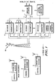
- FIG. 1 shows a prior art trunked radio system that could incorporate the principles of the invention.
- the system comprises a number of subscriber radios (1, 2, and 3), which could be mobiles, portables, or dispatch consoles.
- a group of trunked repeaters (4, 5, 6, 7, 8), a central trunking controller (9), and an antenna system (10) provide the communication channels.
- Each repeater has a receiver and transmitter and provides a single communication channel to the system; the channel designated by reference numeral 8 carries control information.
- Repeaters 4 and 5 provide dispatch service: received audio couples to the transmitter portion of the repeater and is rebroadcast on the paired frequency.
- Repeater 6 provides interconnection service: received audio 11 couples through the wireline interface 12 onto the wireline network; audio from the wireline network couples through the interface and goes on line 14 to the transmitter for broadcast to the interconnected radio subscriber.
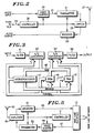
- FIG. 2 shows details of a subscriber two-way radio unit constructed according to the invention.
- the radio includes a transmitter 21 and a receiver 23 coupled through an antenna switch 25 to a common antenna 27.
- Voice audio information from the subscriber goes through a voice buffer 29 before coupling to the modulation port 31 of the transmitter.
- the subscriber depresses a push-to-talk (PTT) switch 33, which causes the trunked controller 35 of the radio to key the transmitter and to send a channel request to the central trunked controller.
- PTT also causes the voice buffer to begin to record a representation of the voice and to continue to record until the user has finished speaking or until the central controller responds with a grant of and an assignment to an information channel.
- Voice buffering allows the user to begin to speak immediately without waiting for a channel assignment.
- the subscriber unit controller may alert the user if the buffer has filled before he has completed speaking, which might occur with a long message and long delay for channel access.
- the subscriber radio controller Upon receiving the channel assignment, the subscriber radio controller causes the voice buffer to reproduce the stored voice information and to couple it to the transmitter for broadcast.
- the buffer functions as a time delay or as a store and forward memory.
- grant to talk will come soon after request, probably before the subscriber has finished speaking.
- the buffer will reproduce delayed information as new information is still being stored.
- assignment delay may exceed the duration of the transmission.
- the buffer will hold the recorded voice until grant of the channel; then it will reproduce the voice information, which will modulate the transmitter.
- channel assignment On subsequent transmissions in a message, channel assignment will likely be more rapid, especially if the system has a recent-user queue, which gives priority to channel requests belonging to continuing conversations. Subscribers hearing a buffered transmission will be aware of delay in a conversation, but the delay time will likely be shorter than in prior art situations because there is no need to manually respond to a call-back signal.
- the voice buffer of the preferred embodiment is a digital storage system in which audio to be buffered is sampled, digitized, and stored in a first-in, first-out (FIFO) memory under control of a microprocessor. Earlier stored samples can be read out from the FIFO as new samples are stored, which allows the FIFO to delay an incoming signal.
- Figure 3 shows details of the voice buffer. Audio input goes through a band-limiting filter 41 to an analog to digital (A/D) converter 43 that provides digital output on data bus 45.
- a microprocessor 47, read-only-memory (ROM) 49, and random-access-memory (RAM) 51 provide control and storage functions. Under command of the microprocessor (which could be part of the radio controller), the A/D samples the filtered input signal at a rate sufficient to allow reconstruction, and it provides digital samples that the microprocessor causes to be stored in the buffer RAM 51.
- the microprocessor causes data from the RAM to couple on the data bus to a digital to analog (D/A) converter 53.
- the D/A produces analog samples, which couple through reconstruction filter 55 and modulate the transmitter.
- the voice buffer has independent controls for addressing read and write data to allow simultaneous input and output of digitized voice information. For example, if samples were taken at a given sampling rate from the input signal, the RAM could read and write at different time slots during each sampling period to allow the input and output sampling rates to maintain synchronism.
- the microprocessor would keep track of separate first-in, first-out addressing pointers for input read and output write data, so that the buffer could function as an elastic FIFO and provide exactly the required time delay to account for the time between beginning of speaking and assignment of a channel on which to transmit.
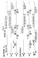
- Figure 4 illustrates the relative timing of events in a dispatch call.
- a subscriber initiates transmission by depressing PTT (101) and talking (102).
- PTT starts voice buffering and initiates a request for channel (103).
- the central controller finds an available channel, assigns it to the call, and sends a grant message (105) to the requesting unit.
- the delay may be longer than the time for which the subscriber speaks, as shown here.
- the requesting unit receives the grant (106) and begins transmission of reproduced voice from the buffer (107).
- the transmission may include beginning of transmission (BOT 108) and end of transmission (EOT 109) signalling to control the repeater.
- the voice channel repeater couples received voice (110) to the paired outbound frequency (111).
- a subscriber responding to the transmission will depress his PTT (120) and state his reply (121).
- a channel request will go to the central controller (122, 123); the controller will respond with channel assignment and grant as one becomes available (124, 125), which may occur before the responding party has finished speaking.
- His subscriber unit will reproduce voice from its buffer (126) even as further speech continues to fill it, and the repeater will receive (127) and re-transmit (128) the reproduced voice.
- the invention also provides for voice buffering in interconnect service.
- Figure 5 shows a channel repeater as it would be configured for wireline interconnection.
- the repeater includes a receiver 61 and a transmitter 62 coupled to a common antenna 63 by a duplexer 64.
- Controller 9 represents control functions performed by the central trunking controller available to the trunked repeaters.
- the received signals are not rebroadcast; instead, received audio 65 couples through the wireline interface 12 onto the network for routing to a wireline subscriber. Audio 67 from the wireline subscriber couples through the interface to the repeater transmitter through a voice buffer 69 such as that described in Figure 3.
- Trunked interconnect operation differs in three aspects from prior art teachings. First, it provides off-line call origination; that is, dialing occurs without use of information channel resources. Second, inbound and outbound frequencies are assigned separately on demand, rather than being paired and retained for the duration of a conversation. Third, because there will be delays in assigning frequencies on demand, voice buffering is provided to allow subscribers to begin speaking immediately, as in the dispatch situation.
- Figure 6 illustrates the steps in an interconnect call originated by a radio subscriber.
- the subscriber composes and verifies the telephone number of the wireline party (201) and activates a function by which his radio sends a request for interconnect service to the central controller (202) and includes the phone number digitally encoded as a data packet (203).
- the controller dials the number (206) and monitors the call progress. If there is a busy signal or no answer after a specified number of rings, the controller notifies the radio subscriber on the control channel. If the wireline party answers (208), the controller initiates the channel assignment routine to assign an outbound channel.
- voice buffering begins to record the response (210) of the called wireline party during the time before a channel becomes available.
- the system can warn the wireline party to wait if the assignment takes longer than the available buffering time: for example, the controller might respond with a message such as "Please wait for a mobile caller.” Up to this point, no transmissions have used information channel resources.
- the trunking controller sends a command (211, 212) for the radio subscriber unit to go to the assigned channel to receive an outbound voice transmission.
- the central controller Upon acknowledgment (213, 214) by the radio subscriber, the central controller transmits buffered voice on the outbound frequency (215).
- PTT triggers a request for channel (219, 220) and causes the radio response to be recorded.
- the central controller responds by de-keying the outbound transmitter and, upon availability, granting an inbound channel (221).
- the subscriber radio Upon receiving the grant (222), the subscriber radio begins to transmit from its voice buffer on the assigned inbound channel (223); the delayed voice will be received (226) and coupled to the wireline (227).
- the transmission may include BOT (224) and EOT (225) signalling to facilitate control operations: e.g., the central controller can use EOT from the subscriber radio to request an outbound channel for the reply (226) forthcoming from the wireline party.
- the controller signals the availability of an outbound channel (229, 230) and, after acknowledgment from the radio subscriber (231, 232), transmits from the wireline interface voice buffer (233, 234).
- Call origination by the wireline party operates similarly, as Figure 7 illustrates.
- the trunked controller alerts the radio party of a call by a paging data packet transmitted on the signalling channel (303, 304).
- the radio unit acknowledges (305, 306), after which the central controller provides ringing tones (307, 308). No request for information channel assignment occurs until the radio subscriber accepts the page from the controller and depresses PTT (310) to answer.
- the radio subscriber may immediately begin to speak (312); his radio will send a channel request (314, 315) in response to PTT.
- the subscriber radio Upon availability and grant of a channel from the central controller (316, 317), the subscriber radio reproduces the buffered reply (318.
- beginning- and end-of-transmission signals (319, 320) control the outbound frequency transmitter.
- the trunked repeater couples the voice reply (321) from the radio to the wireline interface (322), through which the wireline party hears the delayed voice and responds (323).
- the EOT signal (320) from the radio will have begun a channel request procedure, and, when an outbound channel becomes available, it will be granted (324, 325).
- the central controller will transmit the wireline reply from the interface voice buffer (328, 329).
- the system assigns channels according to demand from the simplex radio subscriber.
- the radio subscriber wants to talk, he depresses PTT, and his controller requests an inbound frequency channel.
- the central controller terminates the outbound frequency assignment and, on availability, assigns an inbound path.
- the central controller releases the inbound frequency and assigns an outbound frequency for the wireline reply.
- the normally paired frequency which is not assigned, can be used as demanded for other interconnect calls and can provide increased system capacity and decreased access time for those calls.
- the unassigned frequency would not be suitable for dispatch calls, which simultaneously use both the inbound and the outbound frequencies of the repeater.
- Voice buffering during the assignment delay allows each party to begin speaking without waiting for channel assignment. Buffering also preserves the initial portion of a reply spoken quickly by an inexperienced wireline party, often not heard in prior art interconnect systems because of the slow turn-around from transmit to receive of the two-way radio.
Abstract
Description
- This invention pertains to improved resource allocation and response time in trunked radio communication systems.
- A trunked radio communication system is one in which a number of radio users (subscribers) share a group of communication channels, which is practical when each user requires a channel only a small percentage of the time and few will be communicating simultaneously. Subscribers may use mobile or portable two-way radio units and fixed base dispatch consoles. Typical systems use radio repeaters to provide the communication channels. A repeater receives inbound transmissions from subscriber units on a first path and rebroadcasts the transmissions at higher power on a second, outbound path destined to other units in the field. Typical trunking systems use different assigned frequencies for these simultaneous paths. Each pair of inbound and outbound frequencies makes up a single communication channel, of which a trunked system has several. Channels carrying voice and other message communications are known as information channels; those carrying signalling and control information are known as control channels. These channels commonly involve simplex communication: that is, alternate, rather than simultaneous, transmission and reception.
- A trunked system typically requires that a user desiring to communicate first request permission to access the group of channels and then wait for permission and for an assignment to a particular channel. The trunked system provides means for receiving requests and for transmitting assignments, often by digital signalling on the control channel. If the system operates under the discipline of transmission-trunking, the user retains his channel assignment for only a single transmission; if the system uses message-trunking, the user retains his assignment until completing an entire message comprising several back-and-forth transmissions. Upon completing the transmission or message, respectively, the subscriber relinquishes the channel to the pool of resources for use by others. Because trunked systems involve sharing resources, subscribers must often wait for availability of information channels, in which case the trunk controller responds to a request for channel with a busy signal and notifies the subscriber when a channel later becomes available. U.S. Patent No. 4,635,285, Communication System with Voice Priority for Remote Stations, issued Jan. 6, 1987, to Coombes and incorporated herein by reference, provides details of trunked system operation and signalling protocols.
- Trunked radio systems generally provide dispatch communication and may include capability for wireline interconnection. Dispatch communication is the delivery of messages from a dispatcher to subscribers and the reception of responses from subscribers. It is common for the trunked system to treat all communication positions, i.e., dispatcher and subscribers, equivalently. To make a transmission, a dispatcher or subscriber will place a request for a channel, wait for a grant of permission and an assignment to a channel, and begin to transmit on the assigned channel. After receiving a transmission, a subscriber who wishes to respond will, in turn, begin transmission on an assigned channel. Communication takes place by transmission from a talking subscriber to the central location on an inbound frequency and repeated transmission to listening subscribers on the paired outbound frequency.
- Wireline interconnection usually involves coupling a simplex radio subscriber on the trunked system with a subscriber of a duplex wireline telephone network. The reader is referred to U.S. Patent No. 4,677,656, Telephone-Radio Interconnect System, issued Jun. 30, 1987, to Burke, et al., for details of interconnect communication and call origination.
- A trunked interconnect system following prior art practices will simultaneously assign inbound and outbound frequencies and will maintain the assignments for the duration of a conversation. The radio subscriber transmits under push-to-talk control on the inbound frequency; information received at the repeater couples to the wireline network instead of repeating on the paired outbound frequency. Signals from the wireline subscriber couple to the outbound repeater for broadcast to the radio subscriber; these signals may, but need not, key the repeater by voice-operated control. The duplex wireline subscriber can always hear and may, therefore, be interrupted by the radio subscriber. While transmitting, the simplex radio subscriber does not hear, and cannot be interrupted by, the wireline party.
- Access to the wireline network from a trunked system requires a call origination procedure. One often used is for a radio subscriber to place a request for interconnect service along with his request for a channel. When a channel capable of supporting interconnect service becomes available, the controller assigns and grants permission to use it. The radio subscriber originates the wireline call by transmitting tone or data signalling information (e.g., DTMF dual-tone multi-frequency or packet data encoded telephone number), which couples to the wireline network. The system transmits the call progress information to the radio subscriber on the paired outbound frequency. The radio subscriber hears busy tones or ringing tones and eventually becomes connected with the wireline party or terminates his call attempt.
- Several features of prior art trunked systems have proven objectionable. First, when the system is heavily loaded with radio traffic, subscribers wishing to transmit must wait for vacant channels, which often involves receiving a busy signal and waiting for a call-back with permission to transmit. Upon receiving the call-back announcement, the requesting subscriber may be given a short response time in which to seize the assigned channel. Subscribers experience access delays, and the response time for channel seizure costs valuable communications time.
- Second, prior art systems assign inbound and outbound frequencies together for interconnect traffic, even though the simplex radio subscriber cannot make use of them simultaneously. Interconnect conversations are generally more protracted than dispatch traffic, so unnecessarily assigning paired channels removes valuable resources from the pool available to interconnect calls.
- Third, the call origination procedures taught by the prior art consume valuable information channel time that might be used for other information communications.
- The invention allows a trunked radio subscriber requesting dispatch service to transmit a request for a channel and immediately begin to speak without waiting to receive permission to access the channel. The subscriber unit locally records the information to be transmitted and, upon being assigned a channel, begins to reproduce the information and to transmit it on the channel. If the channel is assigned before the subscriber has finished speaking, the recording and reproduction process provides the effect of time delay to span the actual delay between request for and receipt of permission to transmit. The invention eliminates the need of subscribers to delay transmission and to quickly seize a channel granted after an initial access refusal. The invention also enhances overall response time and increases time available for transmission of information signals.
- According to an aspect of the invention pertaining to interconnect calling, a trunked system alternately assigns inbound and outbound information frequencies only as required for back-and-forth communication between simplex radio and duplex wireline subscribers. Voice buffering allows the parties to begin talking during the delay time between request for and assignment of frequencies. The system further provides for call origination by either radio or wireline subscribers without use of information channels. These procedures, which differ from prior art teachings to assign inbound and outbound frequencies as pairs for the duration of a call and to complete the call origination procedure on an information channel, release resources and make them available to other callers.
- The invention may be better understood by reference to the Drawing, in which:
- Figure 1 shows a typical trunked radio system found in the prior art, including subscriber radio units, a wireline interconnection interface, trunked repeaters, and a trunking controller;
- Figure 2 shows a simplified block diagram of a two-way subscriber radio with provision for voice buffering, constructed according to the invention;
- Figure 3 shows the voice buffering circuits of Figure 2 in greater detail;
- Figure 4 diagrams a trunked dispatch call with voice buffering according to the invention;
- Figure 5 shows a trunked repeater configured for wireline interconnect service with voice buffering provisions according to the invention;
- Figure 6 diagrams a trunked interconnect call originated by a radio subscriber according to the invention; and
- Figure 7 diagrams a trunked interconnect call originated by a wireline subscriber according to the invention.
- Figure 1 shows a prior art trunked radio system that could incorporate the principles of the invention. The system comprises a number of subscriber radios (1, 2, and 3), which could be mobiles, portables, or dispatch consoles. A group of trunked repeaters (4, 5, 6, 7, 8), a central trunking controller (9), and an antenna system (10) provide the communication channels. Each repeater has a receiver and transmitter and provides a single communication channel to the system; the channel designated by
reference numeral 8 carries control information.Repeaters Repeater 6 provides interconnection service: received audio 11 couples through thewireline interface 12 onto the wireline network; audio from the wireline network couples through the interface and goes online 14 to the transmitter for broadcast to the interconnected radio subscriber. - Figure 2 shows details of a subscriber two-way radio unit constructed according to the invention. The radio includes a
transmitter 21 and areceiver 23 coupled through anantenna switch 25 to acommon antenna 27. Voice audio information from the subscriber goes through avoice buffer 29 before coupling to themodulation port 31 of the transmitter. To initiate a transmission, the subscriber depresses a push-to-talk (PTT)switch 33, which causes thetrunked controller 35 of the radio to key the transmitter and to send a channel request to the central trunked controller. PTT also causes the voice buffer to begin to record a representation of the voice and to continue to record until the user has finished speaking or until the central controller responds with a grant of and an assignment to an information channel. Voice buffering allows the user to begin to speak immediately without waiting for a channel assignment. The subscriber unit controller may alert the user if the buffer has filled before he has completed speaking, which might occur with a long message and long delay for channel access. - Upon receiving the channel assignment, the subscriber radio controller causes the voice buffer to reproduce the stored voice information and to couple it to the transmitter for broadcast. Depending on the delay between PTT and the channel assignment, the buffer functions as a time delay or as a store and forward memory. When channel loading conditions are light, grant to talk will come soon after request, probably before the subscriber has finished speaking. The buffer will reproduce delayed information as new information is still being stored. When channel loading conditions are heavy, assignment delay may exceed the duration of the transmission. The buffer will hold the recorded voice until grant of the channel; then it will reproduce the voice information, which will modulate the transmitter. On subsequent transmissions in a message, channel assignment will likely be more rapid, especially if the system has a recent-user queue, which gives priority to channel requests belonging to continuing conversations. Subscribers hearing a buffered transmission will be aware of delay in a conversation, but the delay time will likely be shorter than in prior art situations because there is no need to manually respond to a call-back signal.
- The voice buffer of the preferred embodiment is a digital storage system in which audio to be buffered is sampled, digitized, and stored in a first-in, first-out (FIFO) memory under control of a microprocessor. Earlier stored samples can be read out from the FIFO as new samples are stored, which allows the FIFO to delay an incoming signal. Figure 3 shows details of the voice buffer. Audio input goes through a band-limiting
filter 41 to an analog to digital (A/D)converter 43 that provides digital output ondata bus 45. Amicroprocessor 47, read-only-memory (ROM) 49, and random-access-memory (RAM) 51 provide control and storage functions. Under command of the microprocessor (which could be part of the radio controller), the A/D samples the filtered input signal at a rate sufficient to allow reconstruction, and it provides digital samples that the microprocessor causes to be stored in thebuffer RAM 51. - To reproduce the stored, digitized voice, the microprocessor causes data from the RAM to couple on the data bus to a digital to analog (D/A)
converter 53. The D/A produces analog samples, which couple throughreconstruction filter 55 and modulate the transmitter. - The voice buffer has independent controls for addressing read and write data to allow simultaneous input and output of digitized voice information. For example, if samples were taken at a given sampling rate from the input signal, the RAM could read and write at different time slots during each sampling period to allow the input and output sampling rates to maintain synchronism. The microprocessor would keep track of separate first-in, first-out addressing pointers for input read and output write data, so that the buffer could function as an elastic FIFO and provide exactly the required time delay to account for the time between beginning of speaking and assignment of a channel on which to transmit.
- Figure 4 illustrates the relative timing of events in a dispatch call. A subscriber initiates transmission by depressing PTT (101) and talking (102). PTT starts voice buffering and initiates a request for channel (103). Some time after receiving the request (104), the central controller finds an available channel, assigns it to the call, and sends a grant message (105) to the requesting unit. The delay may be longer than the time for which the subscriber speaks, as shown here. The requesting unit receives the grant (106) and begins transmission of reproduced voice from the buffer (107). The transmission may include beginning of transmission (BOT 108) and end of transmission (EOT 109) signalling to control the repeater. The voice channel repeater couples received voice (110) to the paired outbound frequency (111).
- A subscriber responding to the transmission will depress his PTT (120) and state his reply (121). A channel request will go to the central controller (122, 123); the controller will respond with channel assignment and grant as one becomes available (124, 125), which may occur before the responding party has finished speaking. His subscriber unit will reproduce voice from its buffer (126) even as further speech continues to fill it, and the repeater will receive (127) and re-transmit (128) the reproduced voice.
- The invention also provides for voice buffering in interconnect service. Figure 5 shows a channel repeater as it would be configured for wireline interconnection. The repeater includes a
receiver 61 and atransmitter 62 coupled to acommon antenna 63 by aduplexer 64.Controller 9 represents control functions performed by the central trunking controller available to the trunked repeaters. For interconnect service, the received signals are not rebroadcast; instead, received audio 65 couples through thewireline interface 12 onto the network for routing to a wireline subscriber.Audio 67 from the wireline subscriber couples through the interface to the repeater transmitter through avoice buffer 69 such as that described in Figure 3. - Trunked interconnect operation according to the invention differs in three aspects from prior art teachings. First, it provides off-line call origination; that is, dialing occurs without use of information channel resources. Second, inbound and outbound frequencies are assigned separately on demand, rather than being paired and retained for the duration of a conversation. Third, because there will be delays in assigning frequencies on demand, voice buffering is provided to allow subscribers to begin speaking immediately, as in the dispatch situation.
- Figure 6 illustrates the steps in an interconnect call originated by a radio subscriber. On a keypad, which may be part of the radio microphone, the subscriber composes and verifies the telephone number of the wireline party (201) and activates a function by which his radio sends a request for interconnect service to the central controller (202) and includes the phone number digitally encoded as a data packet (203). Upon receiving the request and data (204, 205), the controller dials the number (206) and monitors the call progress. If there is a busy signal or no answer after a specified number of rings, the controller notifies the radio subscriber on the control channel. If the wireline party answers (208), the controller initiates the channel assignment routine to assign an outbound channel. At the same time, voice buffering begins to record the response (210) of the called wireline party during the time before a channel becomes available. The system can warn the wireline party to wait if the assignment takes longer than the available buffering time: for example, the controller might respond with a message such as "Please wait for a mobile caller." Up to this point, no transmissions have used information channel resources.
- When an outbound frequency becomes available, the trunking controller sends a command (211, 212) for the radio subscriber unit to go to the assigned channel to receive an outbound voice transmission. Upon acknowledgment (213, 214) by the radio subscriber, the central controller transmits buffered voice on the outbound frequency (215). After the radio party has heard the wireline party finish speaking (216), he depresses PTT (217) and responds (218). PTT triggers a request for channel (219, 220) and causes the radio response to be recorded. The central controller responds by de-keying the outbound transmitter and, upon availability, granting an inbound channel (221). Upon receiving the grant (222), the subscriber radio begins to transmit from its voice buffer on the assigned inbound channel (223); the delayed voice will be received (226) and coupled to the wireline (227). The transmission may include BOT (224) and EOT (225) signalling to facilitate control operations: e.g., the central controller can use EOT from the subscriber radio to request an outbound channel for the reply (226) forthcoming from the wireline party. The controller signals the availability of an outbound channel (229, 230) and, after acknowledgment from the radio subscriber (231, 232), transmits from the wireline interface voice buffer (233, 234).
- Call origination by the wireline party operates similarly, as Figure 7 illustrates. When the calling party becomes connected to the interface terminal by dialing the number of a radio subscriber (301, 302), the trunked controller alerts the radio party of a call by a paging data packet transmitted on the signalling channel (303, 304). The radio unit acknowledges (305, 306), after which the central controller provides ringing tones (307, 308). No request for information channel assignment occurs until the radio subscriber accepts the page from the controller and depresses PTT (310) to answer.
- Using the voice buffering of the invention, the radio subscriber may immediately begin to speak (312); his radio will send a channel request (314, 315) in response to PTT. Upon availability and grant of a channel from the central controller (316, 317), the subscriber radio reproduces the buffered reply (318. As described earlier, beginning- and end-of-transmission signals (319, 320) control the outbound frequency transmitter.
- The trunked repeater couples the voice reply (321) from the radio to the wireline interface (322), through which the wireline party hears the delayed voice and responds (323). The EOT signal (320) from the radio will have begun a channel request procedure, and, when an outbound channel becomes available, it will be granted (324, 325). After the radio tunes to the outbound frequency and acknowledges (326, 327), the central controller will transmit the wireline reply from the interface voice buffer (328, 329).
- An important aspect of this overall process is that instead of maintaining a paired frequency assignment for the duration of the call as taught by the prior art, the system assigns channels according to demand from the simplex radio subscriber. When the radio subscriber wants to talk, he depresses PTT, and his controller requests an inbound frequency channel. The central controller terminates the outbound frequency assignment and, on availability, assigns an inbound path. When the delayed transmission from the radio subscriber indicates end-of-transmission, the central controller releases the inbound frequency and assigns an outbound frequency for the wireline reply. The normally paired frequency, which is not assigned, can be used as demanded for other interconnect calls and can provide increased system capacity and decreased access time for those calls. The unassigned frequency would not be suitable for dispatch calls, which simultaneously use both the inbound and the outbound frequencies of the repeater.
- Voice buffering during the assignment delay allows each party to begin speaking without waiting for channel assignment. Buffering also preserves the initial portion of a reply spoken quickly by an inexperienced wireline party, often not heard in prior art interconnect systems because of the slow turn-around from transmit to receive of the two-way radio.
Claims (6)
upon a request by a radio subscriber for assignment to an information channel, assigning only an inbound channel to the radio subscriber and making available for other interconnect calls the outbound channel that would be paired with the inbound channel for dispatch traffic;
after a transmission by the radio subscriber, assigning only an outbound channel to the wireline subscriber and making available for other interconnect calls the inbound channel that would be paired with the outbound channel for dispatch traffic; and
continuing to assign inbound and outbound channels in like manner until a completion of the interconnect call.
upon a request by the radio subscriber for assignment to an information channel, recording, while waiting to receive the assignment, a representation of information to be transmitted by the radio subscriber and, upon receiving the assignment, reproducing and transmitting on the inbound channel at least a part of a delayed version of the representation of the information to be transmitted by the radio subscriber; and
after the transmission by the radio subscriber and while waiting for the wireline subscriber to be assigned an outbound channel, recording a representation of information to be transmitted by the wireline subscriber and, upon being assigned, reproducing and transmitting on the outbound channel at least a part of a delayed version of the representation of the information to be transmitted by the wireline subscriber.
at the radio subscriber, locally encoding a telephone number of the wireline subscriber and, using control channel resources, requesting interconnect service and transmitting a representation of the telephone number;
at a central controller of the trunked radio system, placing a call to the wireline subscriber;
responding to progress information about the call, and, using control channel resources, notifying the radio subscriber of the progress information; and
initiating an assignment of an outbound channel to the wireline subscriber, if the wireline subscriber answers the call.
while waiting for the assignment of the outbound channel, recording a representation of the information to be transmitted from the wireline subscriber;
receiving the assignment; and
upon receiving the assignment, reproducing and transmitting on the outbound channel at least a part of a delayed version of the representation of the information to be transmitted.
means for requesting an assignment to an information channel on which to transmit;
means for receiving the assignment; and
means for transmitting on the information channel;
characterized further by:
means for recording a representation of information to be transmitted, while waiting to receive the assignment; and
means for reproducing, upon receiving the assignment, at least a part of a delayed version of the representation of the information;
and wherein said means for transmitting further functions to transmit at least part of the delayed version.
Applications Claiming Priority (2)
| Application Number | Priority Date | Filing Date | Title |
|---|---|---|---|
| US07/136,601 US4821310A (en) | 1987-12-22 | 1987-12-22 | Transmission trunked radio system with voice buffering and off-line dialing |
| US136601 | 1987-12-22 |
Related Child Applications (3)
| Application Number | Title | Priority Date | Filing Date |
|---|---|---|---|
| EP19930117031 Division EP0583018A3 (en) | 1987-12-22 | 1988-10-20 | Transmission trunked radio system with independent resource assignment |
| EP93117030.2 Division-Into | 1988-10-20 | ||
| EP93117031.0 Division-Into | 1988-10-20 |
Publications (3)
| Publication Number | Publication Date |
|---|---|
| EP0321672A2 true EP0321672A2 (en) | 1989-06-28 |
| EP0321672A3 EP0321672A3 (en) | 1990-07-11 |
| EP0321672B1 EP0321672B1 (en) | 1994-06-15 |
Family
ID=22473545
Family Applications (4)
| Application Number | Title | Priority Date | Filing Date |
|---|---|---|---|
| EP97101016A Withdrawn EP0773694A3 (en) | 1987-12-22 | 1988-10-20 | Transmission trunked radio system with voice buffering and off-line dialling |
| EP88117494A Expired - Lifetime EP0321672B1 (en) | 1987-12-22 | 1988-10-20 | Transmission trunked radio system with voice buffering and off-line dialing |
| EP19930117031 Withdrawn EP0583018A3 (en) | 1987-12-22 | 1988-10-20 | Transmission trunked radio system with independent resource assignment |
| EP19930117030 Withdrawn EP0583017A3 (en) | 1987-12-22 | 1988-10-20 | Transmission trunked radio system with voice buffering and off-line dialling |
Family Applications Before (1)
| Application Number | Title | Priority Date | Filing Date |
|---|---|---|---|
| EP97101016A Withdrawn EP0773694A3 (en) | 1987-12-22 | 1988-10-20 | Transmission trunked radio system with voice buffering and off-line dialling |
Family Applications After (2)
| Application Number | Title | Priority Date | Filing Date |
|---|---|---|---|
| EP19930117031 Withdrawn EP0583018A3 (en) | 1987-12-22 | 1988-10-20 | Transmission trunked radio system with independent resource assignment |
| EP19930117030 Withdrawn EP0583017A3 (en) | 1987-12-22 | 1988-10-20 | Transmission trunked radio system with voice buffering and off-line dialling |
Country Status (6)
| Country | Link |
|---|---|
| US (1) | US4821310A (en) |
| EP (4) | EP0773694A3 (en) |
| JP (1) | JPH01195728A (en) |
| AT (1) | ATE107457T1 (en) |
| DE (1) | DE3850231T2 (en) |
| HK (1) | HK1000240A1 (en) |
Cited By (13)
| Publication number | Priority date | Publication date | Assignee | Title |
|---|---|---|---|---|
| FR2683107A1 (en) * | 1991-10-23 | 1993-04-30 | Trt Telecom Radio Electr | INFORMATION TRANSMISSION SYSTEM ACCORDING TO TIME MULTIPLEX. |
| EP1182895A1 (en) * | 2000-08-15 | 2002-02-27 | Lucent Technologies Inc. | Method and apparatus for performing a voice dispatch call in a digital communication system |
| GB2367209A (en) * | 2000-09-13 | 2002-03-27 | Motorola Inc | Communication terminal with voice signal buffering |
| EP1209852A1 (en) * | 2000-11-27 | 2002-05-29 | Siemens Aktiengesellschaft | Method and device for data transmission |
| WO2003061314A2 (en) * | 2001-12-21 | 2003-07-24 | Qualcomm, Incorporated | Arbitrated audio communication with reduced latency |
| EP1523200A1 (en) * | 2003-10-08 | 2005-04-13 | Research In Motion Limited | Apparatus, and associated method, for facilitating formation of an apparent push-to-talk communication connection |
| WO2005055470A1 (en) * | 2003-11-21 | 2005-06-16 | Motorola Inc | A method of establishing a communication link in a digital communication system |
| WO2005057967A1 (en) * | 2003-12-08 | 2005-06-23 | Kyocera Wireless Corp. | Optimized push-to-talk call setup |
| EP1555839A1 (en) * | 2004-01-15 | 2005-07-20 | Sagem S.A. | Method for transmitting communications by key press on a telephone and associated telephone |
| WO2006044967A1 (en) * | 2004-10-19 | 2006-04-27 | Kyocera Wireless Corp. | Push to talk voice buffering systems and methods in wireless communication calls |
| WO2006118490A1 (en) * | 2005-04-29 | 2006-11-09 | Telefonaktiebolaget Lm Ericsson (Publ) | Method, mobile station and base station system for transmitting data packets in a packet data communication system |
| US7542897B2 (en) | 2002-08-23 | 2009-06-02 | Qualcomm Incorporated | Condensed voice buffering, transmission and playback |
| US8073403B2 (en) | 2003-10-08 | 2011-12-06 | Research In Motion Limited | Apparatus, and associated method, for facilitating formation of an apparent push-to-talk communication connection |
Families Citing this family (31)
| Publication number | Priority date | Publication date | Assignee | Title |
|---|---|---|---|---|
| JPS63181034U (en) * | 1987-05-15 | 1988-11-22 | ||
| US5408515A (en) * | 1988-04-29 | 1995-04-18 | Mobile Telecommunication Technologies | Ground-to-air telephone calling system and related method for directing a call to a particular passenger |
| US5278891A (en) * | 1988-04-29 | 1994-01-11 | Mobile Telecommunication Technologies | Ground-to-air telephone calling system and related method |
| US5109525A (en) * | 1988-12-02 | 1992-04-28 | Delaware | Two-way radio with voice storage |
| CA1309142C (en) * | 1988-12-02 | 1992-10-20 | Daniel K. Nichols | Two-way radio with voice storage |
| US4972355A (en) * | 1989-10-02 | 1990-11-20 | Motorola, Inc. | Method for radiotelephone autonomous registration |
| US5222248A (en) * | 1990-11-01 | 1993-06-22 | Motorola, Inc. | Call hand-off with user selectable site switching |
| IL103230A (en) * | 1991-12-16 | 1995-12-08 | Motorola Inc | Method and apparatus for reducing data loss in a mobile cellular system |
| SE9200915D0 (en) * | 1992-03-24 | 1992-03-24 | Ericsson Telefon Ab L M | METHODS IN A CELLULAR MOBILE RADIO COMMUNINCATION SYSTEM |
| US5555447A (en) * | 1993-05-14 | 1996-09-10 | Motorola, Inc. | Method and apparatus for mitigating speech loss in a communication system |
| DE19549009C2 (en) * | 1995-12-28 | 1998-08-13 | Siemens Ag | Method and radio station for transmitting information over a GSM cellular network |
| US5983099A (en) * | 1996-06-11 | 1999-11-09 | Qualcomm Incorporated | Method/apparatus for an accelerated response to resource allocation requests in a CDMA push-to-talk system using a CDMA interconnect subsystem to route calls |
| US7047012B1 (en) * | 1997-06-03 | 2006-05-16 | Cingular Wireless Ii, Llc | Method and system for providing access to a telecommunications network |
| GB9808952D0 (en) * | 1998-04-27 | 1998-06-24 | Simoco Int Ltd | Mobile radio system |
| JP2000270363A (en) * | 1999-03-15 | 2000-09-29 | Fujitsu Ltd | Communication form control system and its device |
| US6351627B1 (en) * | 1999-04-14 | 2002-02-26 | Texas Instruments Incorporated | Send/receive communication by delayed audio packets |
| US20070195735A1 (en) * | 2006-02-22 | 2007-08-23 | Rosen Eric C | Method of buffering to reduce media latency in group communications on a wireless communication network |
| US8284737B2 (en) | 2000-03-03 | 2012-10-09 | Qualcomm Incorporated | Method of buffering to reduce media latency in group communications on a wireless communication network |
| JP4151191B2 (en) * | 2000-03-27 | 2008-09-17 | 富士通株式会社 | Mobile communication system and component device thereof |
| US6738617B2 (en) * | 2001-05-15 | 2004-05-18 | Qualcomm Incorporated | Controller for reducing latency in a group dormancy-wakeup process in a group communication network |
| US6725053B2 (en) * | 2001-05-15 | 2004-04-20 | Qualcomm Incorporated | Method and apparatus for reducing latency in waking up a group of dormant communication devices |
| US6904288B2 (en) * | 2001-05-15 | 2005-06-07 | Qualcomm Incorporated | Controller for providing an efficient dormant mode for a group communication network |
| JP3750642B2 (en) * | 2002-08-30 | 2006-03-01 | ブラザー工業株式会社 | Communications system |
| US20040162095A1 (en) * | 2003-02-18 | 2004-08-19 | Motorola, Inc. | Voice buffering during call setup |
| US20050143056A1 (en) * | 2003-12-31 | 2005-06-30 | Iyer Prakash R. | Method and apparatus for providing push-to-talk services in a cellular communication system |
| US7477906B2 (en) * | 2004-02-27 | 2009-01-13 | Research In Motion Limited | Methods and apparatus for facilitating the determination of GPS location information for a mobile station without disrupting communications of a voice call |
| US7230930B2 (en) * | 2004-03-23 | 2007-06-12 | Motorola, Inc. | Mode shifting communications system and method |
| JP4545712B2 (en) * | 2006-06-12 | 2010-09-15 | パナソニック株式会社 | PTT terminal |
| JP2009159249A (en) * | 2007-12-26 | 2009-07-16 | Fujitsu Ltd | Communication terminal |
| JP2019161245A (en) * | 2015-07-30 | 2019-09-19 | パナソニック インテレクチュアル プロパティ コーポレーション オブ アメリカPanasonic Intellectual Property Corporation of America | Communication system, communication node, terminal, and communication control method |
| US10630846B2 (en) * | 2018-04-16 | 2020-04-21 | QRT Software, LLC | Intercommunication system with adaptive transmit delay |
Citations (3)
| Publication number | Priority date | Publication date | Assignee | Title |
|---|---|---|---|---|
| US4182989A (en) * | 1975-10-24 | 1980-01-08 | Nissan Motor Company, Inc. | System for establishing a communication link between a ground station and each of vehicle drivers within a limited communication area |
| WO1986003635A1 (en) * | 1984-12-06 | 1986-06-19 | Motorola, Inc. | Duplex interconnect/dispatch trunked radio system |
| US4635285A (en) * | 1984-04-12 | 1987-01-06 | Motorola, Inc. | Communication system with voice priority for remote stations |
Family Cites Families (18)
| Publication number | Priority date | Publication date | Assignee | Title |
|---|---|---|---|---|
| US3772596A (en) * | 1972-10-02 | 1973-11-13 | Sierra Research Corp | Data message repeater system |
| US4148657A (en) * | 1977-10-19 | 1979-04-10 | Minnesota Mining And Manufacturing Company | Silver halide photographic emulsions reactively associated with antifog agents, and photographic elements containing said emulsions |
| JPS5544624A (en) * | 1978-09-25 | 1980-03-29 | Nec Corp | Information input/output unit |
| DE2915308A1 (en) * | 1979-04-14 | 1980-10-23 | Bosch Gmbh Robert | RADIO SYSTEM |
| US4352201A (en) * | 1979-04-30 | 1982-09-28 | M.L. Engineering (Plymouth) Limited | Data transmission system |
| JPS5830778B2 (en) * | 1979-09-17 | 1983-07-01 | 日本電信電話株式会社 | Car group telephone system |
| US4471165A (en) * | 1980-10-28 | 1984-09-11 | Pinetree Systems, Inc. | Portable keyboard operated telecommunications system |
| JPS5829231A (en) * | 1981-08-13 | 1983-02-21 | Hitachi Denshi Ltd | Calling system of radio communication system |
| US4479245A (en) * | 1982-12-21 | 1984-10-23 | Motorola, Inc. | Same frequency repeater for a multiple repeater system |
| US4475246A (en) * | 1982-12-21 | 1984-10-02 | Motorola, Inc. | Simulcast same frequency repeater system |
| US4493090A (en) * | 1982-12-27 | 1985-01-08 | Raytheon Company | Memory system |
| US4677656A (en) * | 1984-06-19 | 1987-06-30 | Motorola, Inc. | Telephone-radio interconnect system |
| US4672601A (en) * | 1984-12-06 | 1987-06-09 | Motorola, Inc. | Duplex interconnect/dispatch trunked radio system |
| JPS61216545A (en) * | 1985-02-14 | 1986-09-26 | Fujitsu Ltd | High speed packet switching system |
| US4675863A (en) * | 1985-03-20 | 1987-06-23 | International Mobile Machines Corp. | Subscriber RF telephone system for providing multiple speech and/or data signals simultaneously over either a single or a plurality of RF channels |
| JPS6225523A (en) * | 1985-07-25 | 1987-02-03 | Nec Corp | Radio communication system |
| US4696051A (en) * | 1985-12-31 | 1987-09-22 | Motorola Inc. | Simulcast transmission system having automtic synchronization |
| US4742514A (en) * | 1986-03-25 | 1988-05-03 | Motorola, Inc. | Method and apparatus for controlling a TDM communication device |
-
1987
- 1987-12-22 US US07/136,601 patent/US4821310A/en not_active Expired - Fee Related
-
1988
- 1988-10-20 EP EP97101016A patent/EP0773694A3/en not_active Withdrawn
- 1988-10-20 EP EP88117494A patent/EP0321672B1/en not_active Expired - Lifetime
- 1988-10-20 DE DE3850231T patent/DE3850231T2/en not_active Expired - Fee Related
- 1988-10-20 EP EP19930117031 patent/EP0583018A3/en not_active Withdrawn
- 1988-10-20 EP EP19930117030 patent/EP0583017A3/en not_active Withdrawn
- 1988-10-20 AT AT88117494T patent/ATE107457T1/en not_active IP Right Cessation
- 1988-12-15 JP JP63315210A patent/JPH01195728A/en active Pending
-
1997
- 1997-09-10 HK HK97101761A patent/HK1000240A1/en not_active IP Right Cessation
Patent Citations (3)
| Publication number | Priority date | Publication date | Assignee | Title |
|---|---|---|---|---|
| US4182989A (en) * | 1975-10-24 | 1980-01-08 | Nissan Motor Company, Inc. | System for establishing a communication link between a ground station and each of vehicle drivers within a limited communication area |
| US4635285A (en) * | 1984-04-12 | 1987-01-06 | Motorola, Inc. | Communication system with voice priority for remote stations |
| WO1986003635A1 (en) * | 1984-12-06 | 1986-06-19 | Motorola, Inc. | Duplex interconnect/dispatch trunked radio system |
Non-Patent Citations (2)
| Title |
|---|
| 36th VEHICULAR TECHNOLOGY CONFERENCE,20-22 MAY 1986 DALLAS (US) pages 194 - 201; K.ZDUNEK: "DESIGN CONSIDERATIONS FOR TRUNKED RADIO SYSTEMS " * |
| JOURNAL OF THE INSTITUTION OF ELECTRONIC AND RADIO ENGINEERS.May/june,1987 no. 3, LONDON GB pages 113 - 118; P.COCKRAM et al: "A standard signalling protocol for Band III trunked systems" * |
Cited By (20)
| Publication number | Priority date | Publication date | Assignee | Title |
|---|---|---|---|---|
| FR2683107A1 (en) * | 1991-10-23 | 1993-04-30 | Trt Telecom Radio Electr | INFORMATION TRANSMISSION SYSTEM ACCORDING TO TIME MULTIPLEX. |
| EP0540081A1 (en) * | 1991-10-23 | 1993-05-05 | Trt Telecommunications Radioelectriques Et Telephoniques | Time multiplexed information transmission system |
| EP1182895A1 (en) * | 2000-08-15 | 2002-02-27 | Lucent Technologies Inc. | Method and apparatus for performing a voice dispatch call in a digital communication system |
| GB2367209A (en) * | 2000-09-13 | 2002-03-27 | Motorola Inc | Communication terminal with voice signal buffering |
| EP1209852A1 (en) * | 2000-11-27 | 2002-05-29 | Siemens Aktiengesellschaft | Method and device for data transmission |
| WO2003061314A2 (en) * | 2001-12-21 | 2003-07-24 | Qualcomm, Incorporated | Arbitrated audio communication with reduced latency |
| WO2003061314A3 (en) * | 2001-12-21 | 2003-10-09 | Qualcomm Inc | Arbitrated audio communication with reduced latency |
| US7542897B2 (en) | 2002-08-23 | 2009-06-02 | Qualcomm Incorporated | Condensed voice buffering, transmission and playback |
| EP1523200A1 (en) * | 2003-10-08 | 2005-04-13 | Research In Motion Limited | Apparatus, and associated method, for facilitating formation of an apparent push-to-talk communication connection |
| US8073403B2 (en) | 2003-10-08 | 2011-12-06 | Research In Motion Limited | Apparatus, and associated method, for facilitating formation of an apparent push-to-talk communication connection |
| WO2005055470A1 (en) * | 2003-11-21 | 2005-06-16 | Motorola Inc | A method of establishing a communication link in a digital communication system |
| US7260414B2 (en) | 2003-12-08 | 2007-08-21 | Kyocera Wireless Corp. | Optimized push-to-talk call setup |
| CN101073276B (en) * | 2003-12-08 | 2010-05-05 | 京瓷无线公司 | Optimized push-to-talk call setup |
| WO2005057967A1 (en) * | 2003-12-08 | 2005-06-23 | Kyocera Wireless Corp. | Optimized push-to-talk call setup |
| FR2865338A1 (en) * | 2004-01-15 | 2005-07-22 | Sagem | METHOD FOR TRANSMITTING COMMUNICATIONS BY ACTUATION OF A BUTTON ON A TELEPHONE AND TELEPHONE THEREFOR |
| EP1555839A1 (en) * | 2004-01-15 | 2005-07-20 | Sagem S.A. | Method for transmitting communications by key press on a telephone and associated telephone |
| WO2006044967A1 (en) * | 2004-10-19 | 2006-04-27 | Kyocera Wireless Corp. | Push to talk voice buffering systems and methods in wireless communication calls |
| US7245940B2 (en) | 2004-10-19 | 2007-07-17 | Kyocera Wireless Corp. | Push to talk voice buffering systems and methods in wireless communication calls |
| CN101076974B (en) * | 2004-10-19 | 2011-11-09 | 京瓷公司 | Method and wireless communication device for processing wireless communication audio frequency information |
| WO2006118490A1 (en) * | 2005-04-29 | 2006-11-09 | Telefonaktiebolaget Lm Ericsson (Publ) | Method, mobile station and base station system for transmitting data packets in a packet data communication system |
Also Published As
| Publication number | Publication date |
|---|---|
| EP0583017A2 (en) | 1994-02-16 |
| EP0583018A2 (en) | 1994-02-16 |
| EP0583017A3 (en) | 1994-05-11 |
| EP0321672A3 (en) | 1990-07-11 |
| US4821310A (en) | 1989-04-11 |
| EP0321672B1 (en) | 1994-06-15 |
| DE3850231T2 (en) | 1994-12-22 |
| EP0773694A2 (en) | 1997-05-14 |
| EP0583018A3 (en) | 1994-04-20 |
| JPH01195728A (en) | 1989-08-07 |
| EP0773694A3 (en) | 1998-02-04 |
| DE3850231D1 (en) | 1994-07-21 |
| HK1000240A1 (en) | 1998-02-06 |
| ATE107457T1 (en) | 1994-07-15 |
Similar Documents
| Publication | Publication Date | Title |
|---|---|---|
| US4821310A (en) | Transmission trunked radio system with voice buffering and off-line dialing | |
| US4748655A (en) | Portable telephones | |
| US5946306A (en) | Allocation of time slots in a mobile communication system | |
| FI77554B (en) | CELLULAERT MOBILRADIOTELEFONSYSTEM MED GEMENSAMT ANROPNINGSSYSTEM FOER MEDDELANDESERVICE. | |
| EP0433256B1 (en) | Telecommunication combination comprising a switched telecommunication network and a portable radio terminal | |
| AU727318B2 (en) | Maintenance of group call in mobile communication system | |
| US20040228292A1 (en) | Method and apparatus for providing full duplex dispatch | |
| EP0800729B1 (en) | Synchronizing a telecommunication connection in a mobile communication system | |
| JPH10500815A (en) | Method for establishing a call in a mobile communication system | |
| US5551063A (en) | Method and apparatus for establishing a private conversation for more than two mobile units in a trunked system | |
| GB2344726A (en) | Providing passive group call subscribers with half-duplex connections | |
| EP1220522B1 (en) | Call screening in a cordless digital system | |
| GB2344725A (en) | Group communication and audio signal selection system | |
| EP1517567B1 (en) | Mobile communications terminal and method | |
| KR0148898B1 (en) | Trs system | |
| US20050026598A1 (en) | System and method for notifying callers | |
| JPH01189240A (en) | Mobile telephone exchange system | |
| JP2712333B2 (en) | Subscriber concentrator communication system | |
| JPH08154268A (en) | Call retrieval method and its equipment at busy radio channel in subscriber radio system | |
| JPS61206333A (en) | Mobile communication system | |
| RU2177672C1 (en) | Method for connecting subscribers of trunking communication system | |
| JP2507577B2 (en) | Simplex communication channel call connection method | |
| JPH048973B2 (en) | ||
| JPH10322770A (en) | Message allowance emergency radio communication system | |
| JPS6172424A (en) | Multi-connection radio exchange system |
Legal Events
| Date | Code | Title | Description |
|---|---|---|---|
| PUAI | Public reference made under article 153(3) epc to a published international application that has entered the european phase |
Free format text: ORIGINAL CODE: 0009012 |
|
| AK | Designated contracting states |
Kind code of ref document: A2 Designated state(s): AT BE CH DE FR GB IT LI LU NL SE |
|
| PUAL | Search report despatched |
Free format text: ORIGINAL CODE: 0009013 |
|
| AK | Designated contracting states |
Kind code of ref document: A3 Designated state(s): AT BE CH DE FR GB IT LI LU NL SE |
|
| 17P | Request for examination filed |
Effective date: 19910110 |
|
| 17Q | First examination report despatched |
Effective date: 19920916 |
|
| ITF | It: translation for a ep patent filed |
Owner name: BARZANO' E ZANARDO ROMA S.P.A. |
|
| GRAA | (expected) grant |
Free format text: ORIGINAL CODE: 0009210 |
|
| AK | Designated contracting states |
Kind code of ref document: B1 Designated state(s): AT BE CH DE FR GB IT LI LU NL SE |
|
| REF | Corresponds to: |
Ref document number: 107457 Country of ref document: AT Date of ref document: 19940715 Kind code of ref document: T |
|
| REF | Corresponds to: |
Ref document number: 3850231 Country of ref document: DE Date of ref document: 19940721 |
|
| ET | Fr: translation filed | ||
| EAL | Se: european patent in force in sweden |
Ref document number: 88117494.0 |
|
| PLBE | No opposition filed within time limit |
Free format text: ORIGINAL CODE: 0009261 |
|
| STAA | Information on the status of an ep patent application or granted ep patent |
Free format text: STATUS: NO OPPOSITION FILED WITHIN TIME LIMIT |
|
| 26N | No opposition filed | ||
| PGFP | Annual fee paid to national office [announced via postgrant information from national office to epo] |
Ref country code: AT Payment date: 19970918 Year of fee payment: 10 |
|
| PGFP | Annual fee paid to national office [announced via postgrant information from national office to epo] |
Ref country code: GB Payment date: 19970930 Year of fee payment: 10 |
|
| PGFP | Annual fee paid to national office [announced via postgrant information from national office to epo] |
Ref country code: FR Payment date: 19971015 Year of fee payment: 10 |
|
| PGFP | Annual fee paid to national office [announced via postgrant information from national office to epo] |
Ref country code: SE Payment date: 19971016 Year of fee payment: 10 |
|
| PGFP | Annual fee paid to national office [announced via postgrant information from national office to epo] |
Ref country code: NL Payment date: 19971023 Year of fee payment: 10 Ref country code: DE Payment date: 19971023 Year of fee payment: 10 |
|
| PGFP | Annual fee paid to national office [announced via postgrant information from national office to epo] |
Ref country code: CH Payment date: 19971027 Year of fee payment: 10 |
|
| PGFP | Annual fee paid to national office [announced via postgrant information from national office to epo] |
Ref country code: BE Payment date: 19971028 Year of fee payment: 10 |
|
| PG25 | Lapsed in a contracting state [announced via postgrant information from national office to epo] |
Ref country code: LU Free format text: LAPSE BECAUSE OF NON-PAYMENT OF DUE FEES Effective date: 19981020 Ref country code: GB Free format text: LAPSE BECAUSE OF NON-PAYMENT OF DUE FEES Effective date: 19981020 Ref country code: AT Free format text: LAPSE BECAUSE OF NON-PAYMENT OF DUE FEES Effective date: 19981020 |
|
| PG25 | Lapsed in a contracting state [announced via postgrant information from national office to epo] |
Ref country code: SE Free format text: LAPSE BECAUSE OF NON-PAYMENT OF DUE FEES Effective date: 19981021 |
|
| PG25 | Lapsed in a contracting state [announced via postgrant information from national office to epo] |
Ref country code: LI Free format text: LAPSE BECAUSE OF NON-PAYMENT OF DUE FEES Effective date: 19981031 Ref country code: CH Free format text: LAPSE BECAUSE OF NON-PAYMENT OF DUE FEES Effective date: 19981031 Ref country code: BE Free format text: LAPSE BECAUSE OF NON-PAYMENT OF DUE FEES Effective date: 19981031 |
|
| PGFP | Annual fee paid to national office [announced via postgrant information from national office to epo] |
Ref country code: LU Payment date: 19990112 Year of fee payment: 10 |
|
| BERE | Be: lapsed |
Owner name: MOTOROLA INC. Effective date: 19981031 |
|
| PG25 | Lapsed in a contracting state [announced via postgrant information from national office to epo] |
Ref country code: NL Free format text: LAPSE BECAUSE OF NON-PAYMENT OF DUE FEES Effective date: 19990501 |
|
| GBPC | Gb: european patent ceased through non-payment of renewal fee |
Effective date: 19981020 |
|
| REG | Reference to a national code |
Ref country code: CH Ref legal event code: PL |
|
| EUG | Se: european patent has lapsed |
Ref document number: 88117494.0 |
|
| PG25 | Lapsed in a contracting state [announced via postgrant information from national office to epo] |
Ref country code: FR Free format text: LAPSE BECAUSE OF NON-PAYMENT OF DUE FEES Effective date: 19990630 |
|
| NLV4 | Nl: lapsed or anulled due to non-payment of the annual fee |
Effective date: 19990501 |
|
| REG | Reference to a national code |
Ref country code: FR Ref legal event code: ST |
|
| PG25 | Lapsed in a contracting state [announced via postgrant information from national office to epo] |
Ref country code: DE Free format text: LAPSE BECAUSE OF NON-PAYMENT OF DUE FEES Effective date: 19990803 |
|
| PG25 | Lapsed in a contracting state [announced via postgrant information from national office to epo] |
Ref country code: IT Free format text: LAPSE BECAUSE OF NON-PAYMENT OF DUE FEES;WARNING: LAPSES OF ITALIAN PATENTS WITH EFFECTIVE DATE BEFORE 2007 MAY HAVE OCCURRED AT ANY TIME BEFORE 2007. THE CORRECT EFFECTIVE DATE MAY BE DIFFERENT FROM THE ONE RECORDED. Effective date: 20051020 |