EP0321927A1 - Elbow joint prosthesis - Google Patents
Elbow joint prosthesis Download PDFInfo
- Publication number
- EP0321927A1 EP0321927A1 EP88121309A EP88121309A EP0321927A1 EP 0321927 A1 EP0321927 A1 EP 0321927A1 EP 88121309 A EP88121309 A EP 88121309A EP 88121309 A EP88121309 A EP 88121309A EP 0321927 A1 EP0321927 A1 EP 0321927A1
- Authority
- EP
- European Patent Office
- Prior art keywords
- component
- ulnar
- boss
- humeral
- axle
- Prior art date
- Legal status (The legal status is an assumption and is not a legal conclusion. Google has not performed a legal analysis and makes no representation as to the accuracy of the status listed.)
- Granted
Links
Images

Classifications
-
- A—HUMAN NECESSITIES
- A61—MEDICAL OR VETERINARY SCIENCE; HYGIENE
- A61F—FILTERS IMPLANTABLE INTO BLOOD VESSELS; PROSTHESES; DEVICES PROVIDING PATENCY TO, OR PREVENTING COLLAPSING OF, TUBULAR STRUCTURES OF THE BODY, e.g. STENTS; ORTHOPAEDIC, NURSING OR CONTRACEPTIVE DEVICES; FOMENTATION; TREATMENT OR PROTECTION OF EYES OR EARS; BANDAGES, DRESSINGS OR ABSORBENT PADS; FIRST-AID KITS
- A61F2/00—Filters implantable into blood vessels; Prostheses, i.e. artificial substitutes or replacements for parts of the body; Appliances for connecting them with the body; Devices providing patency to, or preventing collapsing of, tubular structures of the body, e.g. stents
- A61F2/02—Prostheses implantable into the body
- A61F2/30—Joints
- A61F2/38—Joints for elbows or knees
- A61F2/3804—Joints for elbows or knees for elbows
-
- A—HUMAN NECESSITIES
- A61—MEDICAL OR VETERINARY SCIENCE; HYGIENE
- A61F—FILTERS IMPLANTABLE INTO BLOOD VESSELS; PROSTHESES; DEVICES PROVIDING PATENCY TO, OR PREVENTING COLLAPSING OF, TUBULAR STRUCTURES OF THE BODY, e.g. STENTS; ORTHOPAEDIC, NURSING OR CONTRACEPTIVE DEVICES; FOMENTATION; TREATMENT OR PROTECTION OF EYES OR EARS; BANDAGES, DRESSINGS OR ABSORBENT PADS; FIRST-AID KITS
- A61F2/00—Filters implantable into blood vessels; Prostheses, i.e. artificial substitutes or replacements for parts of the body; Appliances for connecting them with the body; Devices providing patency to, or preventing collapsing of, tubular structures of the body, e.g. stents
- A61F2/02—Prostheses implantable into the body
- A61F2/30—Joints
- A61F2002/30001—Additional features of subject-matter classified in A61F2/28, A61F2/30 and subgroups thereof
- A61F2002/30316—The prosthesis having different structural features at different locations within the same prosthesis; Connections between prosthetic parts; Special structural features of bone or joint prostheses not otherwise provided for
- A61F2002/30329—Connections or couplings between prosthetic parts, e.g. between modular parts; Connecting elements
- A61F2002/30331—Connections or couplings between prosthetic parts, e.g. between modular parts; Connecting elements made by longitudinally pushing a protrusion into a complementarily-shaped recess, e.g. held by friction fit
- A61F2002/30354—Cylindrically-shaped protrusion and recess, e.g. cylinder of circular basis
-
- A—HUMAN NECESSITIES
- A61—MEDICAL OR VETERINARY SCIENCE; HYGIENE
- A61F—FILTERS IMPLANTABLE INTO BLOOD VESSELS; PROSTHESES; DEVICES PROVIDING PATENCY TO, OR PREVENTING COLLAPSING OF, TUBULAR STRUCTURES OF THE BODY, e.g. STENTS; ORTHOPAEDIC, NURSING OR CONTRACEPTIVE DEVICES; FOMENTATION; TREATMENT OR PROTECTION OF EYES OR EARS; BANDAGES, DRESSINGS OR ABSORBENT PADS; FIRST-AID KITS
- A61F2/00—Filters implantable into blood vessels; Prostheses, i.e. artificial substitutes or replacements for parts of the body; Appliances for connecting them with the body; Devices providing patency to, or preventing collapsing of, tubular structures of the body, e.g. stents
- A61F2/02—Prostheses implantable into the body
- A61F2/30—Joints
- A61F2002/30001—Additional features of subject-matter classified in A61F2/28, A61F2/30 and subgroups thereof
- A61F2002/30316—The prosthesis having different structural features at different locations within the same prosthesis; Connections between prosthetic parts; Special structural features of bone or joint prostheses not otherwise provided for
- A61F2002/30329—Connections or couplings between prosthetic parts, e.g. between modular parts; Connecting elements
- A61F2002/30331—Connections or couplings between prosthetic parts, e.g. between modular parts; Connecting elements made by longitudinally pushing a protrusion into a complementarily-shaped recess, e.g. held by friction fit
- A61F2002/30362—Connections or couplings between prosthetic parts, e.g. between modular parts; Connecting elements made by longitudinally pushing a protrusion into a complementarily-shaped recess, e.g. held by friction fit with possibility of relative movement between the protrusion and the recess
- A61F2002/30369—Limited lateral translation of the protrusion within a larger recess
-
- A—HUMAN NECESSITIES
- A61—MEDICAL OR VETERINARY SCIENCE; HYGIENE
- A61F—FILTERS IMPLANTABLE INTO BLOOD VESSELS; PROSTHESES; DEVICES PROVIDING PATENCY TO, OR PREVENTING COLLAPSING OF, TUBULAR STRUCTURES OF THE BODY, e.g. STENTS; ORTHOPAEDIC, NURSING OR CONTRACEPTIVE DEVICES; FOMENTATION; TREATMENT OR PROTECTION OF EYES OR EARS; BANDAGES, DRESSINGS OR ABSORBENT PADS; FIRST-AID KITS
- A61F2/00—Filters implantable into blood vessels; Prostheses, i.e. artificial substitutes or replacements for parts of the body; Appliances for connecting them with the body; Devices providing patency to, or preventing collapsing of, tubular structures of the body, e.g. stents
- A61F2/02—Prostheses implantable into the body
- A61F2/30—Joints
- A61F2002/30001—Additional features of subject-matter classified in A61F2/28, A61F2/30 and subgroups thereof
- A61F2002/30316—The prosthesis having different structural features at different locations within the same prosthesis; Connections between prosthetic parts; Special structural features of bone or joint prostheses not otherwise provided for
- A61F2002/30329—Connections or couplings between prosthetic parts, e.g. between modular parts; Connecting elements
- A61F2002/30331—Connections or couplings between prosthetic parts, e.g. between modular parts; Connecting elements made by longitudinally pushing a protrusion into a complementarily-shaped recess, e.g. held by friction fit
- A61F2002/30362—Connections or couplings between prosthetic parts, e.g. between modular parts; Connecting elements made by longitudinally pushing a protrusion into a complementarily-shaped recess, e.g. held by friction fit with possibility of relative movement between the protrusion and the recess
- A61F2002/3037—Translation along the common longitudinal axis, e.g. piston
- A61F2002/30372—Translation along the common longitudinal axis, e.g. piston with additional means for limiting said translation
-
- A—HUMAN NECESSITIES
- A61—MEDICAL OR VETERINARY SCIENCE; HYGIENE
- A61F—FILTERS IMPLANTABLE INTO BLOOD VESSELS; PROSTHESES; DEVICES PROVIDING PATENCY TO, OR PREVENTING COLLAPSING OF, TUBULAR STRUCTURES OF THE BODY, e.g. STENTS; ORTHOPAEDIC, NURSING OR CONTRACEPTIVE DEVICES; FOMENTATION; TREATMENT OR PROTECTION OF EYES OR EARS; BANDAGES, DRESSINGS OR ABSORBENT PADS; FIRST-AID KITS
- A61F2/00—Filters implantable into blood vessels; Prostheses, i.e. artificial substitutes or replacements for parts of the body; Appliances for connecting them with the body; Devices providing patency to, or preventing collapsing of, tubular structures of the body, e.g. stents
- A61F2/02—Prostheses implantable into the body
- A61F2/30—Joints
- A61F2002/30001—Additional features of subject-matter classified in A61F2/28, A61F2/30 and subgroups thereof
- A61F2002/30621—Features concerning the anatomical functioning or articulation of the prosthetic joint
- A61F2002/30624—Hinged joint, e.g. with transverse axle restricting the movement
-
- A—HUMAN NECESSITIES
- A61—MEDICAL OR VETERINARY SCIENCE; HYGIENE
- A61F—FILTERS IMPLANTABLE INTO BLOOD VESSELS; PROSTHESES; DEVICES PROVIDING PATENCY TO, OR PREVENTING COLLAPSING OF, TUBULAR STRUCTURES OF THE BODY, e.g. STENTS; ORTHOPAEDIC, NURSING OR CONTRACEPTIVE DEVICES; FOMENTATION; TREATMENT OR PROTECTION OF EYES OR EARS; BANDAGES, DRESSINGS OR ABSORBENT PADS; FIRST-AID KITS
- A61F2/00—Filters implantable into blood vessels; Prostheses, i.e. artificial substitutes or replacements for parts of the body; Appliances for connecting them with the body; Devices providing patency to, or preventing collapsing of, tubular structures of the body, e.g. stents
- A61F2/02—Prostheses implantable into the body
- A61F2/30—Joints
- A61F2/38—Joints for elbows or knees
- A61F2/3804—Joints for elbows or knees for elbows
- A61F2002/3813—Joints for elbows or knees for elbows for ulno-humeral joints
-
- A—HUMAN NECESSITIES
- A61—MEDICAL OR VETERINARY SCIENCE; HYGIENE
- A61F—FILTERS IMPLANTABLE INTO BLOOD VESSELS; PROSTHESES; DEVICES PROVIDING PATENCY TO, OR PREVENTING COLLAPSING OF, TUBULAR STRUCTURES OF THE BODY, e.g. STENTS; ORTHOPAEDIC, NURSING OR CONTRACEPTIVE DEVICES; FOMENTATION; TREATMENT OR PROTECTION OF EYES OR EARS; BANDAGES, DRESSINGS OR ABSORBENT PADS; FIRST-AID KITS
- A61F2/00—Filters implantable into blood vessels; Prostheses, i.e. artificial substitutes or replacements for parts of the body; Appliances for connecting them with the body; Devices providing patency to, or preventing collapsing of, tubular structures of the body, e.g. stents
- A61F2/02—Prostheses implantable into the body
- A61F2/30—Joints
- A61F2/38—Joints for elbows or knees
- A61F2/3804—Joints for elbows or knees for elbows
- A61F2002/3822—Humeral components
-
- A—HUMAN NECESSITIES
- A61—MEDICAL OR VETERINARY SCIENCE; HYGIENE
- A61F—FILTERS IMPLANTABLE INTO BLOOD VESSELS; PROSTHESES; DEVICES PROVIDING PATENCY TO, OR PREVENTING COLLAPSING OF, TUBULAR STRUCTURES OF THE BODY, e.g. STENTS; ORTHOPAEDIC, NURSING OR CONTRACEPTIVE DEVICES; FOMENTATION; TREATMENT OR PROTECTION OF EYES OR EARS; BANDAGES, DRESSINGS OR ABSORBENT PADS; FIRST-AID KITS
- A61F2/00—Filters implantable into blood vessels; Prostheses, i.e. artificial substitutes or replacements for parts of the body; Appliances for connecting them with the body; Devices providing patency to, or preventing collapsing of, tubular structures of the body, e.g. stents
- A61F2/02—Prostheses implantable into the body
- A61F2/30—Joints
- A61F2/38—Joints for elbows or knees
- A61F2/3804—Joints for elbows or knees for elbows
- A61F2002/3831—Ulnar components
-
- A—HUMAN NECESSITIES
- A61—MEDICAL OR VETERINARY SCIENCE; HYGIENE
- A61F—FILTERS IMPLANTABLE INTO BLOOD VESSELS; PROSTHESES; DEVICES PROVIDING PATENCY TO, OR PREVENTING COLLAPSING OF, TUBULAR STRUCTURES OF THE BODY, e.g. STENTS; ORTHOPAEDIC, NURSING OR CONTRACEPTIVE DEVICES; FOMENTATION; TREATMENT OR PROTECTION OF EYES OR EARS; BANDAGES, DRESSINGS OR ABSORBENT PADS; FIRST-AID KITS
- A61F2/00—Filters implantable into blood vessels; Prostheses, i.e. artificial substitutes or replacements for parts of the body; Appliances for connecting them with the body; Devices providing patency to, or preventing collapsing of, tubular structures of the body, e.g. stents
- A61F2/02—Prostheses implantable into the body
- A61F2/30—Joints
- A61F2/46—Special tools or methods for implanting or extracting artificial joints, accessories, bone grafts or substitutes, or particular adaptations therefor
- A61F2002/4631—Special tools or methods for implanting or extracting artificial joints, accessories, bone grafts or substitutes, or particular adaptations therefor the prosthesis being specially adapted for being cemented
-
- A—HUMAN NECESSITIES
- A61—MEDICAL OR VETERINARY SCIENCE; HYGIENE
- A61F—FILTERS IMPLANTABLE INTO BLOOD VESSELS; PROSTHESES; DEVICES PROVIDING PATENCY TO, OR PREVENTING COLLAPSING OF, TUBULAR STRUCTURES OF THE BODY, e.g. STENTS; ORTHOPAEDIC, NURSING OR CONTRACEPTIVE DEVICES; FOMENTATION; TREATMENT OR PROTECTION OF EYES OR EARS; BANDAGES, DRESSINGS OR ABSORBENT PADS; FIRST-AID KITS
- A61F2220/00—Fixations or connections for prostheses classified in groups A61F2/00 - A61F2/26 or A61F2/82 or A61F9/00 or A61F11/00 or subgroups thereof
- A61F2220/0025—Connections or couplings between prosthetic parts, e.g. between modular parts; Connecting elements
- A61F2220/0033—Connections or couplings between prosthetic parts, e.g. between modular parts; Connecting elements made by longitudinally pushing a protrusion into a complementary-shaped recess, e.g. held by friction fit
-
- A—HUMAN NECESSITIES
- A61—MEDICAL OR VETERINARY SCIENCE; HYGIENE
- A61F—FILTERS IMPLANTABLE INTO BLOOD VESSELS; PROSTHESES; DEVICES PROVIDING PATENCY TO, OR PREVENTING COLLAPSING OF, TUBULAR STRUCTURES OF THE BODY, e.g. STENTS; ORTHOPAEDIC, NURSING OR CONTRACEPTIVE DEVICES; FOMENTATION; TREATMENT OR PROTECTION OF EYES OR EARS; BANDAGES, DRESSINGS OR ABSORBENT PADS; FIRST-AID KITS
- A61F2310/00—Prostheses classified in A61F2/28 or A61F2/30 - A61F2/44 being constructed from or coated with a particular material
- A61F2310/00005—The prosthesis being constructed from a particular material
- A61F2310/00011—Metals or alloys
- A61F2310/00023—Titanium or titanium-based alloys, e.g. Ti-Ni alloys
Definitions
- elbow joint prostheses are designed to permit limited laxity during supination, pronation and varus-valgus angulation, thereby allowing the tendons and muscles associated with the joint to absorb some of the loads and correspondingly reduce the loads imposed on the prosthesis at the limits of motion.
- One very successful elbow prosthesis developed at the Hospital for Special Surgery (the assignee of the present invention) and produced under license as the "Tri-axialTM Prosthesis” employs a unique "snap-fit" articulation in which a U-shaped plastic bushing attached by small pins to a metal humeral component accepts lateral and medial projections on a boss portion of an ulnar component within depressions in the legs of the bushing.
- the interaction of the bushing and the projections provides rotational and varus-valgus angular laxity in the prosthetic joint by permitting motions of the projections on the ulnar boss within the depressions of the humeral bushing, thereby absorbing energy and reducing loads imposed on the prosthesis.
- Tri-axial Prosthesis has the very important advantages of virtually eliminating prosthesis failures and greatly reducing the possibility of loss of retention, a trade-off for these advantages is an increased likelihood of displacement of the joint - i.e., dislodgement of the ulnar boss from the humeral bushing.
- U.S. Patent No. 3,990,117 describes and shows an elbow joint prosthesis comprising a plastic humeral component and a metal ulnar component joined for articulation by an axle and bushing.
- the bushing is smaller than the holes in the components that receive it, thereby affording varus-vulgus angulation and rotation.
- Load-transfer occurs along convex spherical segmental surfaces on the bifucated head of the humeral component and concave spherical segmental surfaces on the head of the ulnar component.
- the load transfers are often imposed eccentrically of the axes of the humerus and ulnar, because the load-bearing surfaces straddle a connecting boss and recess associated with the hinge connection of the components. Moreover, the locations of load transfers are such that they are transmitted with a large amount of leverage in respect of the cement-prosthesis-bone retention structures, thus presenting significant chances of loosening of the implanted prosthesis.
- An object of the present invention is to provide an elbow joint prosthesis that provides a good functional range of motion with appropriate laxities during supination, pronation and varus-valgus angulations throughout the range of motion, thereby permitting motions of the joint approximating those of the anatomical elbow joint.
- a further object is to eliminate the possibility of dislocation of the joint.
- Still another object is to improve compressive load transfers between the prosthesis components and between the humeral component and the humerus.
- an elbow joint prosthesis that comprises: a metal humeral component that includes a stem portion adapted to be received in the medullary canal of a distal humeral shaft and a head portion adapted to be received in a resected portion of a distal humerus intermediate the internal and external humeral condyles and including a lateral flange and a medial flange defining between them a recess opening distally, anteriorly and posteriorly; a metal ulnar component that includes a stem portion adapted to be received in the medullary canal of the proximal ulnar shaft, a head portion adapted to be received in a resected portion of the olecranon of an ulna and a boss portion extending generally anteriorly from the head portion and adapted to be received in the recess of the humeral component; and a plastic humeral insert component nested in
- the present invention is characterized in that the flanges of the humeral component, the legs of the insert component and the boss portion of the ulnar component have axle holes aligned along a latero-medial axis; in that a metal axle extends through the holes and connects the humeral and ulnar components for articulation; in that a plastic sleeve is interposed between the portions of the axle within the holes of the insert component legs and the ulnar component boss; in that the boss of the ulnar component is in lateral clearance from the walls of the insert component legs and the sleeve is in radial clearance with the axle hole in the ulnar component boss so as to provide laxity under pronation, supination and varus-valgus angulation of the arm; and in that the boss of the ulnar component has a convex spherical articular surface along its superior, anterior and inferior aspects, and the base portion of the insert component bears against an inferior surface of
- the laxity of the prosthesis of the present invention allows rotation and angulation between the upper arm and forearm to extents comparable to those accommodated by the anatomical elbow joint. Such motions are restrained by the soft tissues of the arm, thereby reducing loads on the prosthesis at the nominal limits of motion designed into the prosthesis. Beyond the nominal limits some additional rotation and angulation are permitted by elastic deformation of the plastic insert and sleeve, which absorb the energy of contacts at the limits of free motion and cushion what otherwise might be a sharp impact or shock load that could cause the bone-cement-metal fixation structures to loosen. All transfers of forces between the components are from metal to plastic to metal which not only provides shock absorption but reduces friction.
- Compressive load transfers occur along the convex spherical articular surface of the boss of the ulnar component and the matching concavity in the base of the insert component, a location that lies axially of the humerus and ulna and produces a minimum of leverage of the applied forces on the retention structures of the implanted prosthesis.
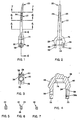
- Figures 1 to 7 are views of the humeral component for the right elbow, as follows:
- the humeral component 20 (Figs. 1 to 7) is made from a surgical grade metal, such as Ti-6Al-4V. It has a stem portion 22, which is curved to fit to the anatomical curvature of the medullary canal of the distal humeral shaft. Cement grooves 24 and 26 on its lateral and medial aspects provide enhanced retention in the polymethyl methacrylate (PMMA) cement used to secure the component to the humerus.
- PMMA polymethyl methacrylate
- the stem is of rectangular cross-section and tapered (Figs.
- the distal humerus is resected by excision of the trochlea and by shaping of the excised region to expose the strong cancellous bone at the inner borders of the epicondyle and epitrochlea to match the bulbous protuberances.
- the implanted humeral component is well-supported laterally, medially and proximally by the bone of the vestigial distal humerus.
- compression loads on the prosthetic joint are transferred from the humeral component to the humerus mainly along the superior aspects of the head portion 28, thereby reducing the possibility of loosening of the prosthesis by loss of the cement-bone bond within the medullary canal or by bone resorption.
- the lateral and medial protuberances 40 and 42 are intentionally shaped differently for optimal fitting to strong bone at the implant site. In the antero-posterior direction the head portion 28 is narrow to maximize the articular range of motion in extension and flexion.
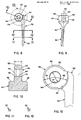
- the ulnar component 50 (Figs. 8 to 13) is also of metal, such as Ti-6Al-4V.
- a tapered stem portion 52 of rectangular cross section and with cement grooves for enhanced fixation is oriented obliquely to a head portion 54, thus establishing an anatomically correct varus angle between the upper arm and forearm.
- the juncture between the stem and head is smoothly curved and presents superiorly and posteriorly a thick and broad plate-like body, the anterior aspect of which consists of two segments of concave cylindrical surfaces that face generally anteriorly.
- the axes of the surfaces 56 and 58 are slightly oblique to each other (see Fig. 10).
- a boss 60 Projecting anteriorly and slightly superiorly from the center of the head portion 54 is a boss 60 having parallel flat sides and a spherical surface 62 presented as a band inferiorly, superiorly, and anteriorly.
- the center of the spherical surface 62 coincides with the axis of a transverse axle hole 64, the center portion 66 of which is circular cylindrical and the end portions 68 and 70 of which are frusto-conical (tapered divergently outwardly).
- the ulnar component is implanted in the proximal ulna, which is prepared by resecting a notch for the head portion 54 in the anterior olecranon process and by opening and widening the floor of the notch for acceptance of the stem into the canal of the proximal ulnar shaft.
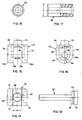
- the insert component 70 (Figs. 14 to 16) is made of ultra high molecular weight polyethylene (UHMWPE) and is symmetrical about its antero-posterior and latero-medial centerlines, which means it can be used in both elbows. It is generally U-shaped and has a round pin 72 that fits into a socket 74 (Fig. 4) in the base portion 28 of the humeral component 20.
- the outward aspect of each leg 76 and 78 has a recess shaped to match the profile of, and thus to receive, a flange 30, 32 of the humeral component and to define a bounding rib 76a, 78a that overlies the inferior, anterior and posterior margins of the respective flanges 30 and 32.
- each leg 76 and 78 has an axle hole 80.
- the distal extremity of each leg 76, 78 is a semi-cylindrical surface having its axis coincident with the axis of the axle holes 80.
- a tubular circular cylindrical sleeve 82 of UHMWPE (Figs. 17 and 18, which are on a still larger scale than are Figs. 14 to 16) is received with a close fit within the axle holes 80 of the legs 76 and 78 of the insert component 70.
- a spherical depression 86 On the inferior surface of the base portion 84 of the insert component is a spherical depression 86, the center of which is at the intersection of the axis of the axle holes 80 with the latero-medial bisecting plane of the insert component 70.
- the axle 90 (Fig. 19) is of metal, such as Ti-6Al-4V, joins all of the components of the assembled prosthesis and, of course, is installed after the humeral and ulnar components have been implanted and the insert component and sleeve have been nested in place in the receiving recess of the humeral component.
- the axle is received with a close fit through the bore of the sleeve 82, and its medial end extends with a close fit into the small axle hole 36 in the flange 32 of the humeral component.
- the head 92 of the axle has a groove 94 that accepts a resilient C-ring (not shown) that is pre-installed in a groove 38a (Fig.
- a tapered surface 96 on the inward border of the axle head expands the C-ring as the axle is pressed home, and the C-ring resiles into the groove 94 to lock the axle in place.
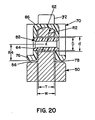
- the prosthesis provides laxity under supination, pronation and varus-valgus angulation by permitting latero-medial cocking and relative axial rotation of the ulnar component relative to the humeral assembly, which consists of the humeral component, insert component, sleeve and axle, due to the above-mentioned clearances. From extension through part of the full range of flexion, compression loads are transmitted at the superior extremity of the ulnar boss to the depression 86 of the insert.
- Cocking and rotational motions of the prosthetic joint occur freely --subject to soft tissue restraint but no restraint by the prosthesis-- until restrained by contacts between the sleeve 82 and the axle hole 64 of the ulnar boss, between one of the surfaces 56, 58 of the ulnar head and the extremity of the corresponding flange 76, 78 of the insert, and between one of the side faces of the ulnar boss and the corresponding contact surfaces 76b, 78b.
Abstract
Description
- Within the past few years, it has become increasingly recognized by orthopaedic surgeons that implant arthroplasty of the elbow is often necessary to restore function to and eliminate pain from elbow joints with severe surface damage. A significant factor in the increased treatment of diseased elbow joints by implant arthroplasty is the availability of well-engineered elbow joint prostheses that minimize failures of the implant and loosening of the cement-bone bond. Early designs provided virtually total constraint, thereby causing large loads to be exerted on the prosthesis at the limits of the range of articular motion and in inhibiting angulation in the varus-valgus plane and laxity in supination and pronation. The high loading produced a high incidence of implant failures and loss of bone-cement retention.
- Presently available elbow joint prostheses are designed to permit limited laxity during supination, pronation and varus-valgus angulation, thereby allowing the tendons and muscles associated with the joint to absorb some of the loads and correspondingly reduce the loads imposed on the prosthesis at the limits of motion. One very successful elbow prosthesis developed at the Hospital for Special Surgery (the assignee of the present invention) and produced under license as the "Tri-axial™ Prosthesis" employs a unique "snap-fit" articulation in which a U-shaped plastic bushing attached by small pins to a metal humeral component accepts lateral and medial projections on a boss portion of an ulnar component within depressions in the legs of the bushing. The interaction of the bushing and the projections provides rotational and varus-valgus angular laxity in the prosthetic joint by permitting motions of the projections on the ulnar boss within the depressions of the humeral bushing, thereby absorbing energy and reducing loads imposed on the prosthesis.
- While the "Tri-axial Prosthesis" has the very important advantages of virtually eliminating prosthesis failures and greatly reducing the possibility of loss of retention, a trade-off for these advantages is an increased likelihood of displacement of the joint - i.e., dislodgement of the ulnar boss from the humeral bushing.
- U.S. Patent No. 3,990,117 (Nov. 9, 1976) describes and shows an elbow joint prosthesis comprising a plastic humeral component and a metal ulnar component joined for articulation by an axle and bushing. The bushing is smaller than the holes in the components that receive it, thereby affording varus-vulgus angulation and rotation. Load-transfer occurs along convex spherical segmental surfaces on the bifucated head of the humeral component and concave spherical segmental surfaces on the head of the ulnar component. The load transfers are often imposed eccentrically of the axes of the humerus and ulnar, because the load-bearing surfaces straddle a connecting boss and recess associated with the hinge connection of the components. Moreover, the locations of load transfers are such that they are transmitted with a large amount of leverage in respect of the cement-prosthesis-bone retention structures, thus presenting significant chances of loosening of the implanted prosthesis.
- An object of the present invention is to provide an elbow joint prosthesis that provides a good functional range of motion with appropriate laxities during supination, pronation and varus-valgus angulations throughout the range of motion, thereby permitting motions of the joint approximating those of the anatomical elbow joint. A further object is to eliminate the possibility of dislocation of the joint. Still another object is to improve compressive load transfers between the prosthesis components and between the humeral component and the humerus.
- The foregoing and other objects are attained, according to the present invention, by an elbow joint prosthesis that comprises: a metal humeral component that includes a stem portion adapted to be received in the medullary canal of a distal humeral shaft and a head portion adapted to be received in a resected portion of a distal humerus intermediate the internal and external humeral condyles and including a lateral flange and a medial flange defining between them a recess opening distally, anteriorly and posteriorly; a metal ulnar component that includes a stem portion adapted to be received in the medullary canal of the proximal ulnar shaft, a head portion adapted to be received in a resected portion of the olecranon of an ulna and a boss portion extending generally anteriorly from the head portion and adapted to be received in the recess of the humeral component; and a plastic humeral insert component nested in the recess and including a base portion and a pair of leg portions selectively engageable between the boss of the ulnar component and the head portion of the humeral component throughout the range of motion of the prosthesis. As described generally thus far, the prosthesis of the present invention is similar to the known "Tri-axial Prosthesis" described above.
- The present invention is characterized in that the flanges of the humeral component, the legs of the insert component and the boss portion of the ulnar component have axle holes aligned along a latero-medial axis; in that a metal axle extends through the holes and connects the humeral and ulnar components for articulation; in that a plastic sleeve is interposed between the portions of the axle within the holes of the insert component legs and the ulnar component boss; in that the boss of the ulnar component is in lateral clearance from the walls of the insert component legs and the sleeve is in radial clearance with the axle hole in the ulnar component boss so as to provide laxity under pronation, supination and varus-valgus angulation of the arm; and in that the boss of the ulnar component has a convex spherical articular surface along its superior, anterior and inferior aspects, and the base portion of the insert component bears against an inferior surface of the head portion of the humeral component and has a concave spherical inferior articular surface complementary to and engageable by the ulnar spherical articular surface throughout the range of motion of the prosthesis for transfer of compressive loads.
- The prosthesis of the present invention may include the following preferred characteristics alone or in various combinations:
- (1) Each leg portion of the insert component has an outwardly extending peripheral U-shaped rib engaging the anterior, posterior and distal aspects of a corresponding flange portion of the humeral component, and the head portion of the ulnar component has generally anteriorly facing concave bearing surfaces, one laterally of and one medially of the boss portion, adapted to engage selectively the respective ribs of the insert component upon selected extents of varus-valgus angulation and pronation-supination rotation of the arm but in clearance with the ribs in the absence of such angulations and rotations.
- (2) The distal portions of the ribs have convex circular cylindrical surfaces having their centers coincident with the axis of the axle, and the bearing surfaces of the head portion of the ulnar component are concave circular cylindrical surfaces that are complementary to and slightly oblique to the cylindrical surfaces of the ribs.
- (3) The axle hole in the boss portion of the ulnar component has a cylindrical central portion and an outwardly tapered lateral portion on each side of the central portion, and the sleeve is in clearance fit with the axle hole of the boss portion so that selected amounts of varus-valgus angulation and pronation-supination rotation of the prothestic joint are afforded without compression binding of the sleeve between the axle hole of the boss portion and the axle.
- (4) The surfaces of the leg portions of the insert component defining the recess have inferiorly divergent segments adjacent their distal extremities, and the boss portion of the ulnar component has lateral and medial surfaces that are normally in clearance with said surfaces of the insert component leg portions so as to allow selected amounts of varus-valgus angulation and pronation-supination rotation of the prosthetic joint without compression binding but are engageable with the divergent segments to restrain such angulation and rotation and absorb energy.
- (5) The head portion of the humeral component has bulbous protuberances on its lateral and medial aspects for enhanced transfer of compression loads from the humeral component to the bone of the inferior distal humerus.
- (6) The bulbous protuberances are shaped to match generally the borders of the olecranon depression.
- The laxity of the prosthesis of the present invention allows rotation and angulation between the upper arm and forearm to extents comparable to those accommodated by the anatomical elbow joint. Such motions are restrained by the soft tissues of the arm, thereby reducing loads on the prosthesis at the nominal limits of motion designed into the prosthesis. Beyond the nominal limits some additional rotation and angulation are permitted by elastic deformation of the plastic insert and sleeve, which absorb the energy of contacts at the limits of free motion and cushion what otherwise might be a sharp impact or shock load that could cause the bone-cement-metal fixation structures to loosen. All transfers of forces between the components are from metal to plastic to metal which not only provides shock absorption but reduces friction. Compressive load transfers occur along the convex spherical articular surface of the boss of the ulnar component and the matching concavity in the base of the insert component, a location that lies axially of the humerus and ulna and produces a minimum of leverage of the applied forces on the retention structures of the implanted prosthesis.
- For a better understanding of the invention, reference may be made to the following description of an exemplary embodiment, taken in conjunction with the figures of the accompanying drawings.
- Figures 1 to 7 are views of the humeral component for the right elbow, as follows:
- Fig. 1 - elevational of the lateral aspect;
- Fig. 2 - elevational of the posterior aspect;
- Fig. 3 - plan of the inferior aspect;
- Fig. 4 - detail partial cross-sectional along 4-4 of Fig. 1 and on an enlarged scale;
- Figs. 5 to 7 - cross-sectionals indicated in Fig. 1.
- Figs. 8 to 13 are views of the ulnar component, as follows:
- Fig. 8 - elevational of the medial aspect;
- Fig. 9 - elevational of anterior aspect;
- Fig. 10 - cross sectional along 10-10 of Fig. 8 on enlarged scale;
- Figs. 11 and 12 - cross-sectionals indicated in Fig. 8;
- Fig. 13 - enlarged detail indicated by
circle 13 in Fig. 8; - Figs. 14 to 16 are inferior plan, anterior elevational and lateral elevational views, respectively, of the humeral insert component;
- Figs. 17 and 18 are half cross-sectional and end elevational views, respectively, of the axle sleeve;
- Fig. 19 is an elevational view of the axle,
- Fig. 20 is a partial assembly showing the insert connected to the ulnar component with the axle sleeve, and
- Fig. 21 is a total assembly of the prosthesis.
- The humeral component 20 (Figs. 1 to 7) is made from a surgical grade metal, such as Ti-6Al-4V. It has a
stem portion 22, which is curved to fit to the anatomical curvature of the medullary canal of the distal humeral shaft.Cement grooves U-shaped head portion 28, the distally dependent lateral andmedial flanges recess 34 that opens inferiorly, anteriorly and posteriorly and haveholes Bulbous protuberances humeral head portion 28 are shaped to match generally the lateral and medial borders of the olecranon depression of the humerus. - The distal humerus is resected by excision of the trochlea and by shaping of the excised region to expose the strong cancellous bone at the inner borders of the epicondyle and epitrochlea to match the bulbous protuberances. Hence, the implanted humeral component is well-supported laterally, medially and proximally by the bone of the vestigial distal humerus. Accordingly, compression loads on the prosthetic joint are transferred from the humeral component to the humerus mainly along the superior aspects of the
head portion 28, thereby reducing the possibility of loosening of the prosthesis by loss of the cement-bone bond within the medullary canal or by bone resorption. Note that the lateral andmedial protuberances head portion 28 is narrow to maximize the articular range of motion in extension and flexion. - The ulnar component 50 (Figs. 8 to 13) is also of metal, such as Ti-6Al-4V. A
tapered stem portion 52 of rectangular cross section and with cement grooves for enhanced fixation is oriented obliquely to ahead portion 54, thus establishing an anatomically correct varus angle between the upper arm and forearm. The juncture between the stem and head is smoothly curved and presents superiorly and posteriorly a thick and broad plate-like body, the anterior aspect of which consists of two segments of concave cylindrical surfaces that face generally anteriorly. The axes of thesurfaces head portion 54 is aboss 60 having parallel flat sides and aspherical surface 62 presented as a band inferiorly, superiorly, and anteriorly. The center of thespherical surface 62 coincides with the axis of atransverse axle hole 64, thecenter portion 66 of which is circular cylindrical and theend portions head portion 54 in the anterior olecranon process and by opening and widening the floor of the notch for acceptance of the stem into the canal of the proximal ulnar shaft. - The insert component 70 (Figs. 14 to 16) is made of ultra high molecular weight polyethylene (UHMWPE) and is symmetrical about its antero-posterior and latero-medial centerlines, which means it can be used in both elbows. It is generally U-shaped and has a
round pin 72 that fits into a socket 74 (Fig. 4) in thebase portion 28 of thehumeral component 20. The outward aspect of eachleg flange bounding rib 76a, 78a that overlies the inferior, anterior and posterior margins of therespective flanges leg axle hole 80. The distal extremity of eachleg cylindrical sleeve 82 of UHMWPE (Figs. 17 and 18, which are on a still larger scale than are Figs. 14 to 16) is received with a close fit within the axle holes 80 of thelegs insert component 70. On the inferior surface of thebase portion 84 of the insert component is aspherical depression 86, the center of which is at the intersection of the axis of the axle holes 80 with the latero-medial bisecting plane of theinsert component 70. - The axle 90 (Fig. 19) is of metal, such as Ti-6Al-4V, joins all of the components of the assembled prosthesis and, of course, is installed after the humeral and ulnar components have been implanted and the insert component and sleeve have been nested in place in the receiving recess of the humeral component. The axle is received with a close fit through the bore of the
sleeve 82, and its medial end extends with a close fit into thesmall axle hole 36 in theflange 32 of the humeral component. Thehead 92 of the axle has agroove 94 that accepts a resilient C-ring (not shown) that is pre-installed in a groove 38a (Fig. 4) in thelarge axle hole 38 in theflange 30. A taperedsurface 96 on the inward border of the axle head expands the C-ring as the axle is pressed home, and the C-ring resiles into thegroove 94 to lock the axle in place. - Several dimensional relationships and configurations of the components provide about 10 degrees of laxity (without restraint by the prosthesis) during pronation, supination and varus-valgus angulation, as follows:
- (1) The latero-medial thickness T (Fig. 10) of the
ulnar boss 60 is less than the width W (Fig. 14) of the receiving recess between thelegs - (2) The outside diameter D (Fig. 17) of the
sleeve 82 is slightly less than the diameter d (Fig. 13) of thecylindrical center part 66 of theaxle hole 64 in theulnar boss 60 so the axle can nutate within theaxle hole 64 to the extent allowed by the tapered end portions of the hole; - (3) The radius R1 of the
spherical surface segment 62 at the margin of the ulnar boss 60 (Fig. 13) is equal to the radius R2 of the spherical depression 86 (Fig. 16) of theinsert component 70; - (4) The radii R3 (Fig. 13) of the
cylindrical surfaces flanges insert component 70. As mentioned above, the radii R3 and R4 have the same center. Therefore, the ulnar component can nutate within the receiving recess of the insert component; - (5) The inner distal extremities of the
legs contact areas insert component 70. - The muscles and tendons of the arms keep the elbow joint tight, which maintains compression contact between the
spherical border 62 of theulnar boss 60 and thedepression 86 of the insert component. In a neutral position of the ulnar boss within the receiving recess in the insert component, there is lateral clearance between the ulnar boss and the legs of the insert and radial clearance between thesleeve 82 and theaxle hole 64 of theulnar boss 60. Compression loads are transmitted from the ulnar boss to thespherical depression 86 in thebase portion 84 of the insert component. The ulnar surfaces 56, 58 are in clearance with the edges of theinsert flanges - The prosthesis provides laxity under supination, pronation and varus-valgus angulation by permitting latero-medial cocking and relative axial rotation of the ulnar component relative to the humeral assembly, which consists of the humeral component, insert component, sleeve and axle, due to the above-mentioned clearances. From extension through part of the full range of flexion, compression loads are transmitted at the superior extremity of the ulnar boss to the
depression 86 of the insert. Cocking and rotational motions of the prosthetic joint occur freely --subject to soft tissue restraint but no restraint by the prosthesis-- until restrained by contacts between thesleeve 82 and theaxle hole 64 of the ulnar boss, between one of thesurfaces flange - All engagements between relatively moving surfaces for all motions (articular, rotational and angular) involve metal to plastic contact, which has two benefits - low friction for freedom of motion and energy absorption of impact loads at the limits of motion. The latter benefit reduces the possibility of loosening. All plastic surfaces subject to loading are backed-up by metal, which isolates stressed areas of plastic from bone and cement and prevents concentrated loads. As mentioned above, the carefully shaped protuberances on the head of the humeral component provide enhanced support for the humeral component by strong bone of the humerus, which provides greater assurance against bone resportion at the implant site.
Claims (7)
- a metal humeral component (20) that includes a stem portion (22) adapted to be received in the medullary canal of a distal humeral shaft and a head portion (28) adapted to be received in a resected portion of a distal humerus intermediate the internal and external humeral condyles and including a lateral flange (30) and a medial flange (32) defining between them a recess (34) opening distally, anteriorly and posteriorly,
- a metal ulnar component (50) that includes a stem portion (52) adapted to be received in the medullary canal of the proximal ulnar shaft, a head portion (54) adapted to be received in a resected portion of the olecranon of an ulna and a boss portion (60) extending generally anteriorly from the head portion (54) and adapted to be received in the recess (34) of the humeral component (20), and
- a plastic humeral insert component (70) nested in the recess (34) and including a base portion (84) and a pair of leg portions (76, 78) selectively engageable between the boss (60) of the ulnar component (50) and the head portion (28) of the humeral component (20) throughout the range of motion of the prosthesis,
characterized in that
- the flanges (30, 32) of the humeral component (20), the legs (76, 78) of the insert component (70) and the boss portion (60) of the ulnar component (50) have aligned axle holes (36, 38, 80, 64) extending latero-medially,
- a metal axle (90) extends through the holes (36, 38, 64, 80) and connects the humeral and ulnar components (20, 50) for articulation,
- a plastic sleeve (82) is interposed between the portions of the axle (90) within the holes (80, 64) of the insert component (70) legs (76, 78) and the ulnar component (50) boss (60),
- the boss (60) of the ulnar component (50) is in lateral clearance from the walls of the insert component (70) legs (76, 78) and the sleeve (82) is in clearance with the hole (64) in the ulnar component (50) boss (60) so as to provide laxity under pronation, supination and varus-valgus angulation of the arm,
- the boss (60) of the ulnar component (50) has a convex spherical articular surface (62) along its superior, anterior and inferior aspects, and
- the base portion (84) of the insert component (70) bears against an inferior surface of the head portion (28) of the humeral component (20) and has a concave spherical inferior articular surface (86) complementary to and engageable by the ulnar spherical articular surface (62) throughout the range of motion of the prosthesis for transfer of compressive loads.
- each leg portion (76, 78) of the insert component (70) has an outwardly extending peripheral U-shaped rib (76a, 78a) engaging the anterior, posterior and distal aspects of a corresponding flange portion (30, 32) of the humeral component (20), and
- the head portion (54) of the ulnar component (50) has generally anteriorly facing concave bearing surfaces (56, 58), one laterally of and one medially of the boss portion (60), adapted to engage selectively the respective ribs 76a, 78a) of the insert component (70) upon selected varus-valgus angulations and pronation-supination rotations of the arm but in clearance with the ribs (76a, 78a) in the absence of such angulations and rotations.
- the distal portions of the ribs (76a, 78a) have convex circular cylindrical surfaces having their centers coincident with the axis of the axle (90) and
- the bearing surfaces (56, 58) of the head portion (54) of the ulnar component (50) are concave circular cylindrical surfaces that are complementary to and slightly oblique to the cylindrical surfaces of the ribs (76a, 78a).
- the axle hole (64) in the boss portion (60) of the ulnar component (50) has a cylindrical central portion (66) and an outwardly tapered lateral portion (68, 70) on each side of the central portion (66), and
- the sleeve (82) is in clearance fit with the axle hole (64) of the boss portion (60) so that selected amounts of varus-valgus angulation and pronation-supination rotation of the prosthetic joint are afforded without compression binding of the sleeve (82) between the axle hole (64) of the boss portion (60) and the axle (90).
characterized in that
- the surfaces of the leg portion (76, 78) of the insert component (70) defining the recess have inferiorly divergent segments (76b, 78b) adjacent their distal extremities, and
- the boss portion (60) of the ulnar component (50) has lateral and medial surfaces (56, 58) that are normally in clearance with said surfaces of the insert component (70) leg portions (76, 78) so as to allow selected amounts of varus-valgus angulation and pronation-supination rotations of the prosthetic joint without compression binding but are engageable with the divergent segments (76b, 78b) to restrain such angulations and rotations and absorb energy.
characterized in that the head portion (28) of the humeral component (20) has bulbous protuberances (40, 42) on its lateral and medial aspects for enhanced transfer of compression loads from the humeral component (20) to the bone of the inferior distal humerus.
Applications Claiming Priority (2)
| Application Number | Priority Date | Filing Date | Title |
|---|---|---|---|
| US136149 | 1987-12-21 | ||
| US07/136,149 US4822364A (en) | 1987-12-21 | 1987-12-21 | Elbow joint prosthesis |
Publications (2)
| Publication Number | Publication Date |
|---|---|
| EP0321927A1 true EP0321927A1 (en) | 1989-06-28 |
| EP0321927B1 EP0321927B1 (en) | 1992-07-08 |
Family
ID=22471537
Family Applications (1)
| Application Number | Title | Priority Date | Filing Date |
|---|---|---|---|
| EP88121309A Expired - Lifetime EP0321927B1 (en) | 1987-12-21 | 1988-12-20 | Elbow joint prosthesis |
Country Status (6)
| Country | Link |
|---|---|
| US (1) | US4822364A (en) |
| EP (1) | EP0321927B1 (en) |
| JP (1) | JP2736085B2 (en) |
| AU (1) | AU614318B2 (en) |
| DE (1) | DE3872685T2 (en) |
| ES (1) | ES2032524T3 (en) |
Cited By (2)
| Publication number | Priority date | Publication date | Assignee | Title |
|---|---|---|---|---|
| EP0493629A1 (en) * | 1989-12-09 | 1992-07-08 | GMT Gesellschaft für medizinische Technik mbH | Elbow endoprosthesis |
| CN105167890A (en) * | 2015-10-26 | 2015-12-23 | 北京威高亚华人工关节开发有限公司 | Multifunctional elbow joint replacement prosthesis |
Families Citing this family (40)
| Publication number | Priority date | Publication date | Assignee | Title |
|---|---|---|---|---|
| GB9213110D0 (en) * | 1992-06-19 | 1992-08-05 | Hila Inc | Prosthesis |
| GB2322304B (en) * | 1997-02-21 | 2001-03-14 | Biomet Ltd | Surgical Tool Aligning Device |
| US6162253A (en) * | 1997-12-31 | 2000-12-19 | Iowa State University Research Foundation, Inc. | Total elbow arthroplasty system |
| US6306171B1 (en) | 1998-12-09 | 2001-10-23 | Iowa State University Research Foundation, Inc. | Total elbow arthroplasty system |
| FR2793404B1 (en) * | 1999-05-14 | 2001-09-14 | Tornier Sa | ELBOW PROSTHESIS |
| GB9921374D0 (en) | 1999-09-10 | 1999-11-10 | Univ Sheffield | An elbow prosthesis |
| US7247170B2 (en) | 2000-07-18 | 2007-07-24 | Biomet Manufacturing Corp. | Elbow prosthesis |
| US9561110B2 (en) | 2000-07-18 | 2017-02-07 | Encore Medical, L.P. | Elbow prosthesis |
| US8932362B2 (en) | 2000-07-18 | 2015-01-13 | Biomet Manufacturing, Llc | Elbow prosthesis |
| US10231839B2 (en) * | 2000-07-18 | 2019-03-19 | Encore Medical, L.P. | Elbow prosthesis |
| US8998995B2 (en) | 2000-07-18 | 2015-04-07 | Biomet Manufacturing, Llc | Elbow prosthesis |
| US9155626B2 (en) | 2012-09-10 | 2015-10-13 | Acumed Llc | Radial head prosthesis with floating articular member |
| FR2826860B1 (en) * | 2001-07-09 | 2004-03-05 | Tornier Sa | ANCILLARY OF POSITION OF A CUBITAL COMPONENT AND / OR A RADIAL COMPONENT OF ELBOW PROSTHESIS |
| FR2855397B1 (en) | 2003-05-28 | 2005-07-15 | Tornier Sa | ELBOW PROSTHESIS |
| ES2622873T3 (en) | 2004-03-11 | 2017-07-07 | Acumed Llc | Bone replacement systems |
| US7449028B2 (en) * | 2004-10-29 | 2008-11-11 | Depuy Products, Inc. | Modular total elbow prosthesis, humeral component and associated kit |
| US20060100713A1 (en) * | 2004-10-29 | 2006-05-11 | Ball Robert J | Mobile bearing total elbow prosthesis, ulnar component, and associated kit |
| US20060111789A1 (en) * | 2004-10-29 | 2006-05-25 | Ball Robert J | Modular total elbow prosthesis, instruments and associated method |
| US20060111788A1 (en) * | 2004-10-29 | 2006-05-25 | Ball Robert J | Mobile bearing total elbow prosthesis, humeral component, and associated method |
| US7160329B2 (en) * | 2004-12-01 | 2007-01-09 | Mayo Foundation For Medical Research And Education | Radial-capitellar implant |
| US20060224243A1 (en) * | 2005-03-31 | 2006-10-05 | Zimmer Technology, Inc. | Elbow prosthesis |
| JP4919248B2 (en) * | 2005-05-31 | 2012-04-18 | 博泰 池上 | Artificial elbow joint |
| US8012214B2 (en) | 2005-09-27 | 2011-09-06 | Randall Lane Acker | Joint prosthesis |
| US8034113B2 (en) * | 2005-09-27 | 2011-10-11 | Randall Lane Acker | Joint prosthesis and method of implanting same |
| JP2009542325A (en) * | 2006-06-28 | 2009-12-03 | メイヨ フオンデーシヨン フオー メデイカル エジユケーシヨン アンド リサーチ | Artificial elbow joint |
| EP2114311A2 (en) * | 2007-02-10 | 2009-11-11 | Small Bone Innovations, Inc. | Radial head implant and related instrument |
| US9034050B2 (en) | 2009-09-18 | 2015-05-19 | Biomet Manufacturing, Llc | Elbow prosthesis |
| US20110230972A1 (en) * | 2009-09-18 | 2011-09-22 | Biomet Manufacturing Corp. | Elbow resurfacing prosthesis |
| US10195038B2 (en) * | 2009-11-16 | 2019-02-05 | Limacorporate Spa | Elbow replacement apparatus and methods |
| US8968411B2 (en) * | 2009-12-17 | 2015-03-03 | Zimmer, Inc. | Modular elbow prosthesis |
| US8840673B2 (en) * | 2011-09-21 | 2014-09-23 | Linares Medical Devices, Llc | Implantable elbow joint assembly with spherical inter-support |
| US11213400B2 (en) | 2012-05-07 | 2022-01-04 | Encore Medical, L.P. | Elbow prosthesis |
| US8936647B2 (en) | 2012-06-22 | 2015-01-20 | Zimmer, Inc. | Elbow prosthesis |
| US10201374B2 (en) | 2012-06-22 | 2019-02-12 | Zimmer, Inc. | Assembly tool for a prosthesis |
| US9039779B2 (en) | 2013-03-13 | 2015-05-26 | Biomet Manufacturing, Llc | Adjustable lateral articulating condyle |
| US9949839B2 (en) * | 2013-03-13 | 2018-04-24 | Wright Medical Technology, Inc. | Revision implant augments, systems, and methods |
| US9763792B2 (en) | 2015-10-01 | 2017-09-19 | Acumed Llc | Radial head prosthesis with rotate-to-lock interface |
| GB201607859D0 (en) * | 2016-05-05 | 2016-06-22 | Smirthwaite Paul T And Smirthwaite Amie D | Canine prosthetic elbow joint |
| US10136998B2 (en) | 2016-08-30 | 2018-11-27 | Wright Medical Technology, Inc. | Revision total ankle implants |
| CN109966031A (en) * | 2019-04-29 | 2019-07-05 | 中南大学湘雅医院 | A kind of elbow joint |
Citations (3)
| Publication number | Priority date | Publication date | Assignee | Title |
|---|---|---|---|---|
| US3990117A (en) * | 1975-01-22 | 1976-11-09 | Pritchard Rowland W | Elbow joint prosthesis |
| FR2395013A1 (en) * | 1977-06-22 | 1979-01-19 | Sulzer Ag | JOINT PROSTHESIS |
| US4293963A (en) * | 1980-02-14 | 1981-10-13 | Zimmer Usa, Inc. | Unrestrained elbow prosthesis |
Family Cites Families (7)
| Publication number | Priority date | Publication date | Assignee | Title |
|---|---|---|---|---|
| US3918101A (en) * | 1973-10-02 | 1975-11-11 | Jean Lagrange | Total knee-joint prosthesis |
| US3996624A (en) * | 1975-02-28 | 1976-12-14 | United States Surgical Corporation | Prosthetic knee joint |
| DE2549318C3 (en) * | 1975-11-04 | 1981-10-29 | Dadurian, Aram, Dr.Med. | Knee joint prosthesis |
| US4131956A (en) * | 1977-02-14 | 1979-01-02 | Richards Manufacturing Company, Inc. | Elbow prosthesis |
| SU719623A1 (en) * | 1978-03-20 | 1980-03-05 | Кузбасский научно-исследовательский институт травматологии и реабилитации | Endoprothesis for elbow joint |
| US4383337A (en) * | 1980-10-22 | 1983-05-17 | Zimmer Usa, Inc. | Elbow prosthesis |
| US4655778A (en) * | 1985-08-12 | 1987-04-07 | Harrington Arthritis Research Center | Joint prosthesis |
-
1987
- 1987-12-21 US US07/136,149 patent/US4822364A/en not_active Expired - Lifetime
-
1988
- 1988-12-14 AU AU26856/88A patent/AU614318B2/en not_active Ceased
- 1988-12-20 ES ES198888121309T patent/ES2032524T3/en not_active Expired - Lifetime
- 1988-12-20 EP EP88121309A patent/EP0321927B1/en not_active Expired - Lifetime
- 1988-12-20 DE DE8888121309T patent/DE3872685T2/en not_active Expired - Fee Related
- 1988-12-21 JP JP63320726A patent/JP2736085B2/en not_active Expired - Lifetime
Patent Citations (3)
| Publication number | Priority date | Publication date | Assignee | Title |
|---|---|---|---|---|
| US3990117A (en) * | 1975-01-22 | 1976-11-09 | Pritchard Rowland W | Elbow joint prosthesis |
| FR2395013A1 (en) * | 1977-06-22 | 1979-01-19 | Sulzer Ag | JOINT PROSTHESIS |
| US4293963A (en) * | 1980-02-14 | 1981-10-13 | Zimmer Usa, Inc. | Unrestrained elbow prosthesis |
Cited By (2)
| Publication number | Priority date | Publication date | Assignee | Title |
|---|---|---|---|---|
| EP0493629A1 (en) * | 1989-12-09 | 1992-07-08 | GMT Gesellschaft für medizinische Technik mbH | Elbow endoprosthesis |
| CN105167890A (en) * | 2015-10-26 | 2015-12-23 | 北京威高亚华人工关节开发有限公司 | Multifunctional elbow joint replacement prosthesis |
Also Published As
| Publication number | Publication date |
|---|---|
| AU614318B2 (en) | 1991-08-29 |
| ES2032524T3 (en) | 1993-02-16 |
| EP0321927B1 (en) | 1992-07-08 |
| JPH01236049A (en) | 1989-09-20 |
| US4822364A (en) | 1989-04-18 |
| AU2685688A (en) | 1989-06-22 |
| DE3872685D1 (en) | 1992-08-13 |
| DE3872685T2 (en) | 1993-02-25 |
| JP2736085B2 (en) | 1998-04-02 |
Similar Documents
| Publication | Publication Date | Title |
|---|---|---|
| EP0321927B1 (en) | Elbow joint prosthesis | |
| US4834758A (en) | Bone prosthesis for the leg and thigh | |
| CN109561969B (en) | Elbow replacement device and method | |
| US4634444A (en) | Semi-constrained artificial joint | |
| JP3875305B2 (en) | Elliptic dome-shaped patella prosthesis | |
| US7722676B2 (en) | Articulating implant system | |
| US4352212A (en) | Joint prosthesis | |
| US5326365A (en) | Ankle implant | |
| US5916269A (en) | Wear reduced acetabular component | |
| EP0822792B1 (en) | Tibial prosthesis with mobile bearing member | |
| US6206926B1 (en) | Prosthetic knee joint with enhanced posterior stabilization and dislocation prevention features | |
| US4156296A (en) | Great (large) toe prosthesis and method of implanting | |
| CA1296137C (en) | Wrist joint prosthesis | |
| JPH0880311A (en) | Kneepan femur joint assembly as prosthetic apparatus | |
| JP2005532089A (en) | Self-aligning knee prosthesis | |
| JPH07144005A (en) | Knee prosthesis | |
| JPS5841857B2 (en) | finger joint prosthesis | |
| AU728533B2 (en) | Prosthetic knee joint with enhanced posterior stabilization and dislocation prevention features | |
| US11173038B2 (en) | Total ankle prosthesis | |
| RU2114580C1 (en) | Endoprosthesis of knee-joint | |
| RU2107475C1 (en) | Elbow joint endoprosthesis | |
| Otis et al. | The HSS modular linked system for segmental replacement | |
| WO2013190573A1 (en) | Knee joint prosthesis | |
| US11596519B2 (en) | Hinge knee assembly guide | |
| WO2004000175A1 (en) | Unicompartmental prosthetic knee joint device |
Legal Events
| Date | Code | Title | Description |
|---|---|---|---|
| PUAI | Public reference made under article 153(3) epc to a published international application that has entered the european phase |
Free format text: ORIGINAL CODE: 0009012 |
|
| AK | Designated contracting states |
Kind code of ref document: A1 Designated state(s): BE DE ES FR GB IT NL SE |
|
| 17P | Request for examination filed |
Effective date: 19891228 |
|
| 17Q | First examination report despatched |
Effective date: 19910325 |
|
| GRAA | (expected) grant |
Free format text: ORIGINAL CODE: 0009210 |
|
| ITF | It: translation for a ep patent filed |
Owner name: BARZANO' E ZANARDO MILANO S.P.A. |
|
| AK | Designated contracting states |
Kind code of ref document: B1 Designated state(s): BE DE ES FR GB IT NL SE |
|
| REF | Corresponds to: |
Ref document number: 3872685 Country of ref document: DE Date of ref document: 19920813 |
|
| ET | Fr: translation filed | ||
| REG | Reference to a national code |
Ref country code: ES Ref legal event code: FG2A Ref document number: 2032524 Country of ref document: ES Kind code of ref document: T3 |
|
| PLBE | No opposition filed within time limit |
Free format text: ORIGINAL CODE: 0009261 |
|
| STAA | Information on the status of an ep patent application or granted ep patent |
Free format text: STATUS: NO OPPOSITION FILED WITHIN TIME LIMIT |
|
| 26N | No opposition filed | ||
| EAL | Se: european patent in force in sweden |
Ref document number: 88121309.4 |
|
| PGFP | Annual fee paid to national office [announced via postgrant information from national office to epo] |
Ref country code: SE Payment date: 19991202 Year of fee payment: 12 Ref country code: DE Payment date: 19991202 Year of fee payment: 12 |
|
| PGFP | Annual fee paid to national office [announced via postgrant information from national office to epo] |
Ref country code: GB Payment date: 19991203 Year of fee payment: 12 Ref country code: FR Payment date: 19991203 Year of fee payment: 12 |
|
| PGFP | Annual fee paid to national office [announced via postgrant information from national office to epo] |
Ref country code: NL Payment date: 19991213 Year of fee payment: 12 |
|
| PGFP | Annual fee paid to national office [announced via postgrant information from national office to epo] |
Ref country code: ES Payment date: 19991223 Year of fee payment: 12 |
|
| PGFP | Annual fee paid to national office [announced via postgrant information from national office to epo] |
Ref country code: BE Payment date: 19991224 Year of fee payment: 12 |
|
| PG25 | Lapsed in a contracting state [announced via postgrant information from national office to epo] |
Ref country code: GB Free format text: LAPSE BECAUSE OF NON-PAYMENT OF DUE FEES Effective date: 20001220 |
|
| PG25 | Lapsed in a contracting state [announced via postgrant information from national office to epo] |
Ref country code: SE Free format text: LAPSE BECAUSE OF NON-PAYMENT OF DUE FEES Effective date: 20001221 |
|
| PG25 | Lapsed in a contracting state [announced via postgrant information from national office to epo] |
Ref country code: BE Free format text: LAPSE BECAUSE OF NON-PAYMENT OF DUE FEES Effective date: 20001231 |
|
| BERE | Be: lapsed |
Owner name: NEW YORK SOCIETY FOR THE RELIEF OF THE RUPTURED A Effective date: 20001231 |
|
| PG25 | Lapsed in a contracting state [announced via postgrant information from national office to epo] |
Ref country code: NL Free format text: LAPSE BECAUSE OF NON-PAYMENT OF DUE FEES Effective date: 20010701 |
|
| GBPC | Gb: european patent ceased through non-payment of renewal fee |
Effective date: 20001220 |
|
| EUG | Se: european patent has lapsed |
Ref document number: 88121309.4 |
|
| PG25 | Lapsed in a contracting state [announced via postgrant information from national office to epo] |
Ref country code: FR Free format text: LAPSE BECAUSE OF NON-PAYMENT OF DUE FEES Effective date: 20010831 |
|
| NLV4 | Nl: lapsed or anulled due to non-payment of the annual fee |
Effective date: 20010701 |
|
| REG | Reference to a national code |
Ref country code: FR Ref legal event code: ST |
|
| PG25 | Lapsed in a contracting state [announced via postgrant information from national office to epo] |
Ref country code: DE Free format text: LAPSE BECAUSE OF NON-PAYMENT OF DUE FEES Effective date: 20011002 |
|
| PG25 | Lapsed in a contracting state [announced via postgrant information from national office to epo] |
Ref country code: ES Free format text: LAPSE BECAUSE OF NON-PAYMENT OF DUE FEES Effective date: 20011221 |
|
| REG | Reference to a national code |
Ref country code: ES Ref legal event code: FD2A Effective date: 20020112 |
|
| PG25 | Lapsed in a contracting state [announced via postgrant information from national office to epo] |
Ref country code: IT Free format text: LAPSE BECAUSE OF NON-PAYMENT OF DUE FEES;WARNING: LAPSES OF ITALIAN PATENTS WITH EFFECTIVE DATE BEFORE 2007 MAY HAVE OCCURRED AT ANY TIME BEFORE 2007. THE CORRECT EFFECTIVE DATE MAY BE DIFFERENT FROM THE ONE RECORDED. Effective date: 20051220 |