EP0323378A2 - Oscillating mirror arrangement for the deviation of electromagnetic radiation - Google Patents
Oscillating mirror arrangement for the deviation of electromagnetic radiation Download PDFInfo
- Publication number
- EP0323378A2 EP0323378A2 EP88440112A EP88440112A EP0323378A2 EP 0323378 A2 EP0323378 A2 EP 0323378A2 EP 88440112 A EP88440112 A EP 88440112A EP 88440112 A EP88440112 A EP 88440112A EP 0323378 A2 EP0323378 A2 EP 0323378A2
- Authority
- EP
- European Patent Office
- Prior art keywords
- mirror
- winding
- elastic support
- magnets
- modes
- Prior art date
- Legal status (The legal status is an assumption and is not a legal conclusion. Google has not performed a legal analysis and makes no representation as to the accuracy of the status listed.)
- Withdrawn
Links
Images


Classifications
-
- H—ELECTRICITY
- H01—ELECTRIC ELEMENTS
- H01F—MAGNETS; INDUCTANCES; TRANSFORMERS; SELECTION OF MATERIALS FOR THEIR MAGNETIC PROPERTIES
- H01F7/00—Magnets
- H01F7/06—Electromagnets; Actuators including electromagnets
- H01F7/066—Electromagnets with movable winding
-
- G—PHYSICS
- G01—MEASURING; TESTING
- G01R—MEASURING ELECTRIC VARIABLES; MEASURING MAGNETIC VARIABLES
- G01R9/00—Instruments employing mechanical resonance
- G01R9/02—Vibration galvanometers, e.g. for measuring current
-
- G—PHYSICS
- G02—OPTICS
- G02B—OPTICAL ELEMENTS, SYSTEMS OR APPARATUS
- G02B26/00—Optical devices or arrangements for the control of light using movable or deformable optical elements
- G02B26/08—Optical devices or arrangements for the control of light using movable or deformable optical elements for controlling the direction of light
Definitions
- the present invention relates to an oscillating mirror device for the deflection of electromagnetic rays.
- Such devices generally consist of rotating mirrors mounted on an axis and controlled either by high-speed motors or by electromagnets.
- the device according to the invention meets this requirement because it makes a mirror vibrate from zero to several kilo-Hertz, thus opening the door to numerous applications which will be explained below.
- the device according to the invention has the essential characteristic of comprising a mirror integral with a coil located in a field intense magnetic and capable of oscillating at high frequency on a support made of an elastic material on which the mirror-coil assembly is fixed by gluing.
- the elastic support while ensuring the damping of the oscillations of the mirror-winding assembly, makes it possible to avoid the use of mechanical parts in friction or in rotation, such as ball bearings which gradually deteriorate in the weather; this results in exemplary reliability of the device according to the invention.
- control of the device according to the invention does not require the implementation of a high power electronic assembly, as is the case for existing devices, since a few watts may be sufficient to control it.
- the device according to the invention also offers the advantage of a linearity of operation from O Hertz to several kilo-Hertz, which constitutes another superiority over most of the existing systems, some of which only operate at one frequency.
- the magnets used in the device according to the invention are in fact magnets of energy product greater than 100 kj / m3, capable of creating high-intensity magnetic fields.
- These high power magnets are made of a magnetic material of the Neodyne-Iron type, the energy product of which can exceed 200 kj / m3.
- the magnets used in the device according to the invention may consist of a set of two magnets, one of which approximately affects the shape of a "U" and the other the shape of a parallelepiped, placed in the of the first.
- They can also consist of three sintered plates of a magnetic material of the Neodyne-Iron type arranged in parallel on a support, made or not of the same material.
- the mirror support is fixed to the median element by bonding using an appropriate adhesive which may be of the cyanacrylate type, the mirror-coil assembly coming to cover said support.
- the elastic support used can be made either of a purely elastic material or having a low damping coefficient, or of a material having a high damping coefficient, depending on the expected response.
- the system may have a particularly satisfactory response curve, such as that shown in the attached FIG. 2, where i (t) denotes the intensity of the current passing through the coil, ⁇ (t) the angular response of the mirror and ⁇ the system rise time to 63%.
- the material used in this case is advantageously a polyurethane, such as that sold under the name "SORBOTHANE”.
- the system can only be used at its own resonant frequency, unless its electronic control incorporates a filter intended to compensate for the system's own resonance.
- the material used in this case can be any elastic material, such as a natural latex or a synthetic elastomer latex of the styrene-butadiene or styrene-butadiene-styrene type.
- This elastic support supports the mirror-winding assembly, which is fixed to it by bonding by means of an appropriate adhesive, such as a cyanacrylate.
- the mirror used in the device according to the invention is advantageously a mirror combining lightness, rigidity, temperature resistance and optical performance.
- the material used as a support for the reflecting surface can be an extremely fine glass, of thickness less than 0.2 mm, berylium of thickness less than 0.4 mm, or even a polysulfone.
- the silvering or aluminizing constituting the reflecting surface of the mirror must advantageously have the widest possible reflection spectrum to be able to cover applications ranging from infrared to X-rays.
- the winding implemented in the device according to the invention is made of a metallic conductor which may be copper or a complex alloy of high conductivity.
- the metallic conductor used can affect the shape of a wire, in which case the winding is formed in superimposed turns, on one or two layers.
- This wire can be very thin, of the order of a few hundredths of a millimeter in diameter, if a very miniaturized device is desired. It is thus possible to use, by way of example, an enamelled copper wire of 4/100 mm in diameter, formed in 100 turns superposed in 2 layers.
- the winding can also consist of an inlay on the material constituting the support of the reflecting surface of the mirror, in which case the mirror occupies the central part of this support and is surrounded by the inlay constituting the winding, which takes approximately the form of a spiral.
- the winding consists of a metal wire formed in turns, it is preferably made without support, so as to contribute to the lightness of the device.
- the mirror is fixed to the winding by gluing by means of an appropriate glue, such as a cyanacrylate, this fixing preferably being carried out on two opposite sides of the polygon formed by the turns.
- an appropriate glue such as a cyanacrylate
- the mirror-winding assembly is, as has already been said, fixed by gluing to the elastic support, itself also fixed by gluing to the middle magnet of the set of magnets used.
- This fixing of the mirror-coil assembly on the elastic support can be done in different ways corresponding to different configurations of said elastic support.
- the fixing can thus be done either on the mirror alone, or both on the mirror and the winding.
- the winding roughly affects the shape of a rectangular parallelepiped
- the mirror is glued on the two long sides of the rectangle which constitutes the upper face of this parallelepiped
- the winding mirror assembly covers the median magnet of the set of magnets used .
- the elastic support can have the shape of a rectangular parallelepiped, a barrel or a coil, or any other suitable shape, and be fixed only on the mirror.
- the elastic support can consist of a block glued both to the mirror and to the winding.
- the elastic support may consist of two inverted “L” elements, each of which is fixed on the one hand to the median magnet, and on the other hand to an internal face of the parallelepiped configured by the winding.
- the elastic support may consist of two elements located on either side of the median magnet and supporting two opposite sides of the parallelepiped configured by the winding.
- the winding is made up of metallic inlays formed around the mirror on the surface which supports the silvering or the aluminum.
- the mirror is fixed on the elastic support, which can take the form of a rectangular parallelepiped, a barrel or a coil, and which is fixed on the median magnet.
- the winding is supplied by a source of electric current or voltage comprising means for modulating the intensity, the frequency and the shape of the current admitted into the winding.
- a source of electric current or voltage comprising means for modulating the intensity, the frequency and the shape of the current admitted into the winding.
- the mirror starts to oscillate at a frequency equal to that of the current, the amplitude of the oscillations being a function both of the intensity of the magnetic field and of the maximum amplitude of the current.
- the oscillations of the mirror can be advantageously used to deflect electromagnetic rays, the control of the assembly being carried out by appropriate electronic means.
- a particularly advantageous embodiment of the device according to the invention guaranteesing its reproducibility, consists in adding to the integral winding of the mirror a secondary winding of smaller dimensions, secured to one of the two faces of the winding which are in the air gaps formed by the three parallel magnets, and positioned in such a way that it cannot collect any current induced by the main winding, the only current appearing there being that induced by its movement inside the magnetic field created by the magnets.
- the control mode implemented for current processing can be either a digital control mode, or an analog control mode such as a proportional control, a derivative control, an integral control, a proportional control, a proportional integral servo, a derivative integral servo, or a derivative integral proportional servo.
- the derivative proportional control mode which consists of a variable gain amplifier followed by a voltage subtractor, making it possible to subtract the voltage corresponding to the current from the control voltage main winding, which is equivalent to creating an adjustable electronic brake which allows an equally adjustable control of the instantaneous position of the mirror.
- the secondary winding used in this device according to the invention advantageously has a rectangular shape and its arrangement with respect to the main winding is advantageously such that the plane of its turns is perpendicular to all of the parallel planes defined by the turns of the main winding.
- the turns of the secondary winding according to the invention can be in small numbers, of the order of 1 to 10, two turns usually sufficient to give completely satisfactory results.
- the device according to the invention can find numerous applications in all sectors of the technique capable of calling upon the deflection of electromagnetic rays, whether it is their emission or their reception.
- - in emission deflection of a laser beam using a double device, either for the realization of drawings or graphics on any support, or for the realization of cuts or engravings, in the case of lasers of strong power.
- - in reception scanning of a plan or a volume for Infra-Red cameras.
- - in transmission-reception pattern recognition by laser or X-rays: laser-copiers, photocopiers.
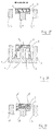
- the magnet 1 having two outer elements 1a and 1c and the middle magnet 1b.
- the mirror 2 is fixed by gluing on the one hand to the coil 3 supplied with current by electric wires 5 and on the other hand to the elastic support 4 itself fixed by gluing to the median magnet 1b.
- the mirror-winding assembly oscillates between two extreme positions, one of which is shown in dotted lines.
- FIG. 2 represents a response curve of a device according to the invention in which the support of the mirror is made of an elastic material with a high coefficient damping i (t) denotes the intensity of the current flowing through the coil, ⁇ (t) the angular response of the mirror and ⁇ the system rise time at 63%.
- FIG. 3a represents an elastic support constituted by a block fixed both to the mirror 2 and to the winding 3.
- FIG. 3b represents an elastic support made up of two elements 4a and 4b, each of which supports one side of the winding 3, the mirror 2 being able to rest on a knife 6 shown in dotted lines.
- FIG. 3c represents an elastic support made up of two elements 4a and 4b, therefore each is fixed to an internal face of the winding 3.
- the median magnet 1b is surmounted by an elastic support 4 which supports, by being integral with it, a mirror 2 secured to a coil 3 affecting the shape of a rectangular parallelepiped and supplied with current by electric wires 5.
- the voltage at the output of the subtractor 9 is applied to a power amplifier 11, the output of which supplies the main winding 3.
- a device according to the invention in accordance with that shown in FIG. 1 consists of three sintered Neodymium-Iron plates 10 mm long, 10 mm high and 3 mm thick, the middle plate being lowered by 1 mm in relation to the two external plates and being surmounted by a polyurethane support 10 mm long, 1 mm high and 1 mm thick.
- a polyurethane support 10 mm long, 1 mm high and 1 mm thick On this support is fixed, by means of a glue based on cyanacrylate, a silicon mirror of 2/10 mm thick fixed by gluing to a coil of 4 mm high made up of 100 turns of enamelled copper wire of diameter 4/100 mm, which covers the middle plate.
- the maximum admissible voltage is 10 volts, i.e. a current of 0.2 A, the resistance of such a winding being about 50 ohms. This results in a peak power of 2 watts.
- the control means required for this device are linear amplifiers which can dissipate powers of the order of 2 watts.
- a triangular electrical signal applied to this device makes it possible to obtain a uniform scanning in time, the angular speed of the mirror being uniform in absolute value.
- Such a device can allow the digitization of images by means of a ray deflected by two mirrors arranged so that one can scan with one the X axis of a plane and with the other the Y axis of the same plan.
- FIG. 4 appended An illustrative example of a device according to the invention as shown in FIG. 4 appended consists of a device such as that which has just been described, to which is added a secondary winding. To this end, a small coil consisting of two parallel turns forming a rectangle 8 mm long and 2 mm high is fixed by bonding to one of the faces of the coil used.
- This small coil connected to an electronic control system integrating a variable gain amplifier and a voltage subtractor itself connected, via a power amplifier, to the main coil, gives the device exemplary reliability and reproducibility.
Abstract
Description
La présente invention a pour objet un dispositif à miroir oscillant pour la déviation de rayons électromagnétiques.The present invention relates to an oscillating mirror device for the deflection of electromagnetic rays.
On sait que des dispositifs apparentés aux galvanomètres sont mis en oeuvre depuis longtemps dans différents secteurs de la technique : ainsi les premiers oscilloscopes fonctionnaient avec des systèmes à miroir oscillant.It is known that devices related to galvanometers have been used for a long time in different fields of technology: thus the first oscilloscopes worked with oscillating mirror systems.
De tels dispositifs sont généralement constitués de miroirs tournants montés sur axe et pilotés soit par des moteurs à grande vitesse, soit par des électro-aimants.Such devices generally consist of rotating mirrors mounted on an axis and controlled either by high-speed motors or by electromagnets.
La nécessité de pousser les performances de ces systèmes a conduit les demandeurs à orienter leurs recherches vers la mise au point d'un dispositif susceptible de faire osciller un miroir à grande vitesse de façon contrôlable et modulable.The need to push the performance of these systems has led the applicants to direct their research towards the development of a device capable of causing a mirror to oscillate at high speed in a controllable and modular manner.
Le dispositif selon l'invention répond à cette exigence car il permet de faire vibrer un miroir de zéro à plusieurs kilo-Hertz, ouvrant ainsi la porte à ne nombreuses applications qui seront exposées plus loin.The device according to the invention meets this requirement because it makes a mirror vibrate from zero to several kilo-Hertz, thus opening the door to numerous applications which will be explained below.
Le dispositif selon l'invention présente la caractéristique essentielle de comporter un miroir solidaire d'un bobinage situé dans un champ magnétique intense et susceptible d'osciller à grande fréquence sur un support réalisé en un matériau élastique sur lequel l'ensemble miroir-bobinage est fixé par collage.The device according to the invention has the essential characteristic of comprising a mirror integral with a coil located in a field intense magnetic and capable of oscillating at high frequency on a support made of an elastic material on which the mirror-coil assembly is fixed by gluing.
La mise en oeuvre d'un support élastique et d'un champ magnétique intense dans le dispositif selon l'invention présente un certain nombre d'avantages remarquables par rapport aux dispositifs existants, tant en ce qui concerne la vitesse d'oscillation déjà évoquée qu'en ce qui concerne la fiabilité et la compacité du système, ainsi que la puissance électrique qu'il requiert pour son fonctionnement.The use of an elastic support and an intense magnetic field in the device according to the invention has a certain number of remarkable advantages compared to existing devices, both with regard to the oscillation speed already mentioned that 'with regard to the reliability and compactness of the system, as well as the electrical power it requires for its operation.
En effet, le support élastique, tout en assurant l'amortissement des oscillations de l'ensemble miroir-bobinage, permet d'éviter le recours à des pièces mécaniques en frottement ou en rotation, telles que des roulements à bille qui se détériorent progressivement dans le temps; il en résulte une fiabilité exemplaire du dispositif selon l'invention.Indeed, the elastic support, while ensuring the damping of the oscillations of the mirror-winding assembly, makes it possible to avoid the use of mechanical parts in friction or in rotation, such as ball bearings which gradually deteriorate in the weather; this results in exemplary reliability of the device according to the invention.
Par ailleurs, la commande du dispositif selon l'invention ne nécessite pas la mise en oeuvre d'un ensemble électronique de grande puissance, comme c'est le cas pour les dispositifs existants, puisque quelques watts peuvent suffire pour le piloter.Furthermore, the control of the device according to the invention does not require the implementation of a high power electronic assembly, as is the case for existing devices, since a few watts may be sufficient to control it.
Ce fait, joint à la simplicité du dispositif, permet au système selon l'invention de présenter l'avantage supplémentaire d'une compacité considérablement réduite allant jusqu'à la miniaturisation, le volume de l'ensemble pouvant être inférieur au dixième de celui des systèmes existants (de l'ordre de 12 mm x 10 mm x 15 mm).This fact, combined with the simplicity of the device, allows the system according to the invention to have the additional advantage of a considerably reduced compactness going up to miniaturization, the volume of the assembly possibly being less than one tenth that of existing systems (of the order of 12 mm x 10 mm x 15 mm).
Enfin, le dispositif selon l'invention offre également l'avantage d'une linéarité de fonctionnement de O Hertz à plusieurs kilo-Hertz, ce qui constitue une autre supériorité sur la plupart des systèmes existants, dont certains ne fonctionnent qu'à une seule fréquence.Finally, the device according to the invention also offers the advantage of a linearity of operation from O Hertz to several kilo-Hertz, which constitutes another superiority over most of the existing systems, some of which only operate at one frequency.
Tous les avantages qui viennent d'être exposés résultent en des performances tout à fait exceptionnelles du dispositif selon l'invention, qui peut être miniaturisé à l'extrême, ces performances exceptionnelles tenant, ainsi qu'il a déjà été dit, à la mise en oeuvre conjointe d'aimants de grande puissance et d'un support du miroir aux propriétés élastiques.All the advantages that have just been exposed result in quite exceptional performances of the device according to the invention, which can be miniaturized to the extreme, these exceptional performances holding, as has already been said, the joint implementation of high power magnets and a mirror support with elastic properties.
Les aimants mis en oeuvre dans le dispositif selon l'invention sont en effet des aimants de produit d'énergie supérieur à 100 kj/m³, aptes à créer des champs magnétiques de grande intensité.The magnets used in the device according to the invention are in fact magnets of energy product greater than 100 kj / m³, capable of creating high-intensity magnetic fields.
Ces aimants de grande puissance sont réalisés dans un matériau magnétique du type Néodyne-Fer, dont le produit d'énergie peut dépasser 200 kj/m³.These high power magnets are made of a magnetic material of the Neodyne-Iron type, the energy product of which can exceed 200 kj / m³.
Les aimants mis en oeuvre dans le dispositif selon l'invention peuvent être constitués d'un ensemble de deux aimants dont l'un affecte approximativement la forme d'un "U" et l'autre la forme d'un parallélépipède, placé dans l'entrefer du premier.The magnets used in the device according to the invention may consist of a set of two magnets, one of which approximately affects the shape of a "U" and the other the shape of a parallelepiped, placed in the of the first.
Ils peuvent être également constitués de trois plaquettes frittées d'un matériau magnétique du type Néodyne-Fer disposées parallèlement sur un support, réalisé ou non dans le même matériau.They can also consist of three sintered plates of a magnetic material of the Neodyne-Iron type arranged in parallel on a support, made or not of the same material.
Ils peuvent être aussi constitués d'un seul bloc affectant grossièrement la forme d'un "E".They can also consist of a single block roughly affecting the shape of an "E".
Dans l'un et l'autre cas, le support du miroir est fixé sur l'élément médian par collage au moyen d'une colle appropriée qui peut être du type cyanacrylate, l'ensemble miroir-bobinage venant coiffer ledit support.In both cases, the mirror support is fixed to the median element by bonding using an appropriate adhesive which may be of the cyanacrylate type, the mirror-coil assembly coming to cover said support.
Le support élastique mis en oeuvre peut être réalisé soit en un matériau purement élastique ou présentant un faible coefficient d'amortissement, soit en un matériau présentant un fort coefficient d'amortissement, selon la réponse attendue.The elastic support used can be made either of a purely elastic material or having a low damping coefficient, or of a material having a high damping coefficient, depending on the expected response.
Dans le cas où le support du miroir est réalisé en un matériau élastique présentant un fort coefficient d'amortissement, le système peut présenter une courbe de réponse particulièrement satisfaisante, telle que celle représentée sur la figure 2 annexée, où i(t) désigne l'intensité du courant traversant la bobine, α (t) la réponse angulaire du miroir et τ le temps de montée du système à 63 %.In the case where the mirror support is made of an elastic material having a high coefficient damping, the system may have a particularly satisfactory response curve, such as that shown in the attached FIG. 2, where i (t) denotes the intensity of the current passing through the coil, α (t) the angular response of the mirror and τ the system rise time to 63%.
Le matériau mis en oeuvre dans ce cas est avantageusement un polyuréthane, tel celui commercialisé sous la dénomination "SORBOTHANE".The material used in this case is advantageously a polyurethane, such as that sold under the name "SORBOTHANE".
Dans le cas où le support du miroir est réalisé en un matériau purement élastique ou présentant un faible coefficient d'amortissement, le système ne peut être utilisé qu'à sa fréquence de résonance propre, à moins que sa commande électronique n'intègre un filtre destiné à compenser la résonance propre du système.In the case where the mirror support is made of a purely elastic material or with a low damping coefficient, the system can only be used at its own resonant frequency, unless its electronic control incorporates a filter intended to compensate for the system's own resonance.
Le matériau mis en oeuvre dans ce cas peut être n'importe quel matériau élastique, tel qu'un latex naturel ou un latex d'élastomère de synthèse du type styrène-butadiène ou styrène-butadiène-styrène.The material used in this case can be any elastic material, such as a natural latex or a synthetic elastomer latex of the styrene-butadiene or styrene-butadiene-styrene type.
Ce support élastique, ainsi qu'il a déjà été dit, supporte l'ensemble miroir-bobinage, qui lui est fixé par collage au moyen d'une colle appropriée, telle qu'un cyanacrylate.This elastic support, as has already been said, supports the mirror-winding assembly, which is fixed to it by bonding by means of an appropriate adhesive, such as a cyanacrylate.
Le miroir mis en oeuvre dans le dispositif selon l'invention est avantageusement un miroir alliant légèreté, rigidité, tenue en température et performances optiques.The mirror used in the device according to the invention is advantageously a mirror combining lightness, rigidity, temperature resistance and optical performance.
Le matériau utilisé comme support de la surface réfléchissante peut être un verre extrêmement fin, d'épaisseur inférieure à O,2 mm du bérylium d'épaisseur inférieure à O,4 mm ou encore une polysulfone.The material used as a support for the reflecting surface can be an extremely fine glass, of thickness less than 0.2 mm, berylium of thickness less than 0.4 mm, or even a polysulfone.
L'argenture ou l'aluminure constituant la surface réfléchissante du miroir doit avantageusement présenter un spectre de réflexion le plus large possible pour pouvoir couvrir des applications allant de l'infra-rouge aux rayons X.The silvering or aluminizing constituting the reflecting surface of the mirror must advantageously have the widest possible reflection spectrum to be able to cover applications ranging from infrared to X-rays.
Le bobinage mis en oeuvre dans le dispositif selon l'invention est réalisé en un conducteur métallique pouvant être le cuivre ou un alliage complexe de conductivité elevée.The winding implemented in the device according to the invention is made of a metallic conductor which may be copper or a complex alloy of high conductivity.
Le conducteur métallique mis en oeuvre peut affecter la forme d'un fil, auquel cas le bobinage est formé en spires superposées, sur une ou deux couches.The metallic conductor used can affect the shape of a wire, in which case the winding is formed in superimposed turns, on one or two layers.
Ce fil peut être très fin, de l'ordre de quelques centièmes de millimètres de diamétre, si l'on veut un dispositif très miniaturisé. On peut ainsi mettre en oeuvre, à titre d'exemple, un fil de cuivre émaillé de 4/100 mm de diamètre, formé en 100 spires superposées en 2 couches.This wire can be very thin, of the order of a few hundredths of a millimeter in diameter, if a very miniaturized device is desired. It is thus possible to use, by way of example, an enamelled copper wire of 4/100 mm in diameter, formed in 100 turns superposed in 2 layers.
Le bobinage peut également consister en une incrustation sur le matériau constituant le support de la surface réfléchissante du miroir, auquel cas le miroir occupe la partie centrale de ce support et est entouré de l'incrustation constituant le bobinage, lequel prend approximativement la forme d'une spirale.The winding can also consist of an inlay on the material constituting the support of the reflecting surface of the mirror, in which case the mirror occupies the central part of this support and is surrounded by the inlay constituting the winding, which takes approximately the form of a spiral.
Dans le cas où le bobinage est constitué d'un fil métallique formé en spires, il est de préférence réalisé sans support, de manière à contribuer à la légèreté du dispositif.In the case where the winding consists of a metal wire formed in turns, it is preferably made without support, so as to contribute to the lightness of the device.
Dans ce cas, le miroir est fixé sur le bobinage par collage au moyen d'une colle appropriée, telle qu'un cyanacrylate, cette fixation se faisant de préférence sur deux côtés opposés du polygone formé par les spires.In this case, the mirror is fixed to the winding by gluing by means of an appropriate glue, such as a cyanacrylate, this fixing preferably being carried out on two opposite sides of the polygon formed by the turns.
L'ensemble miroir-bobinage est, ainsi qu'il a déjà été dit, fixé par collage sur le support élastique, lui-même fixé également par collage sur l'aimant médian de l'ensemble d'aimants mis en oeuvre.The mirror-winding assembly is, as has already been said, fixed by gluing to the elastic support, itself also fixed by gluing to the middle magnet of the set of magnets used.
Cette fixation de l'ensemble miroir-bobinage sur le support élastique peut se faire de différentes façons correspondant à différentes configurations dudit support élastique. La fixation peut ainsi se faire soit sur le miroir seul, soit à la fois sur le miroir et le bobinage.This fixing of the mirror-coil assembly on the elastic support can be done in different ways corresponding to different configurations of said elastic support. The fixing can thus be done either on the mirror alone, or both on the mirror and the winding.
Ainsi, dans un premier mode de réalisation du dispositif selon l'invention, le bobinage affecte grossièrement la forme d'un parallélépipède rectangle, le miroir est collé sur les deux grands côtés du rectangle qui constitue la face supérieure de ce parallélépipède, et l'ensemble miroir bobinage vient coiffer l'aimant médian de l'ensemble d'aimants mis en oeuvre.Thus, in a first embodiment of the device according to the invention, the winding roughly affects the shape of a rectangular parallelepiped, the mirror is glued on the two long sides of the rectangle which constitutes the upper face of this parallelepiped, and the winding mirror assembly covers the median magnet of the set of magnets used .
Selon une variante de ce mode de réalisation du dispositif selon l'invention, le support élastique peut affecter la forme d'un parallélépipède rectangle, d'un tonneau ou d'une bobine, ou toute autre forme appropriée, et être fixé uniquement sur le miroir.According to a variant of this embodiment of the device according to the invention, the elastic support can have the shape of a rectangular parallelepiped, a barrel or a coil, or any other suitable shape, and be fixed only on the mirror.
Selon une autre variante de ce mode de réalisation, le support élastique peut être constitué d'un bloc collé à la fois au miroir et au bobinage.According to another variant of this embodiment, the elastic support can consist of a block glued both to the mirror and to the winding.
Selon une autre variante encore, le support élastique peut être constitué de deux éléments en "L" inversé dont chacun est fixé d'une part à l'aimant médian, et d'autre part à une face interne du parallélépipède configuré par le bobinage.According to yet another variant, the elastic support may consist of two inverted "L" elements, each of which is fixed on the one hand to the median magnet, and on the other hand to an internal face of the parallelepiped configured by the winding.
Enfin, selon une dernière variante, le support élastique peut être constitué de deux éléments situés de part et d'autre de l'aimant médian et supportant deux côtés opposés du parallélépipède configuré par le bobinage.Finally, according to a last variant, the elastic support may consist of two elements located on either side of the median magnet and supporting two opposite sides of the parallelepiped configured by the winding.
Dans un second mode de réalisation du dispositif selon l'invention, le bobinage est constitué d'incrustations métalliques ménagées, autour du miroir, sur la surface qui en supporte l'argenture ou l'aluminure.In a second embodiment of the device according to the invention, the winding is made up of metallic inlays formed around the mirror on the surface which supports the silvering or the aluminum.
Dans ce mode de réalisation, le miroir est fixé sur le support élastique, qui peut affecter la forme d'un parallélépipède rectangle, d'un tonneau ou d'une bobine, et qui est fixé sur l'aimant médian.In this embodiment, the mirror is fixed on the elastic support, which can take the form of a rectangular parallelepiped, a barrel or a coil, and which is fixed on the median magnet.
Dans tous les cas, le bobinage est alimenté par une source de courant ou de tension électrique comportant des moyens pour moduler l'intensité, la fréquence et la forme du courant admis dans le bobinage. Sous l'action du courant électrique et du champ magnétique, le miroir se met à osciller à une fréquence égale à celle du courant, l'amplitude des oscillations étant fonction tout à la fois de l'intensité du champ magnétique et de l'amplitude maximale du courant.In all cases, the winding is supplied by a source of electric current or voltage comprising means for modulating the intensity, the frequency and the shape of the current admitted into the winding. Under the action of the electric current and the magnetic field, the mirror starts to oscillate at a frequency equal to that of the current, the amplitude of the oscillations being a function both of the intensity of the magnetic field and of the maximum amplitude of the current.
Ces paramètres étant convenablement choisis, les oscillations du miroir peuvent être avantageusement utilisées pour dévier des rayons électromagnétiques, le pilotage de l'ensemble étant réalisé par des moyens électroniques appropriés.These parameters being suitably chosen, the oscillations of the mirror can be advantageously used to deflect electromagnetic rays, the control of the assembly being carried out by appropriate electronic means.
Un mode de réalisation particulièrement avantageux du dispositif selon l'invention, garantissant sa reproductibilité, consiste à adjoindre au bobinage solidaire du miroir un bobinage secondaire de moindres dimensions, solidarisé à l'une des deux faces du bobinage qui se trouvent dans les entrefers formés par les trois aimants parallèles, et positionné de telle manière qu'il ne puisse recueillir aucun courant induit par le bobinage principal, le seul courant y apparaîssant étant celui induit par son déplacement à l'intérieur du champ magnétique créé par les aimants.A particularly advantageous embodiment of the device according to the invention, guaranteeing its reproducibility, consists in adding to the integral winding of the mirror a secondary winding of smaller dimensions, secured to one of the two faces of the winding which are in the air gaps formed by the three parallel magnets, and positioned in such a way that it cannot collect any current induced by the main winding, the only current appearing there being that induced by its movement inside the magnetic field created by the magnets.
Un traitement convenable de ce courant par un mode d'asservissement approprié permet un réglage de la position de la vitesse et de l'accélération instantanées du miroir, satisfaisant aux exigences de linéarité du système.Proper treatment of this current by an appropriate servo control mode allows the position of the instantaneous speed and acceleration of the mirror to be adjusted, meeting the linearity requirements of the system.
Le mode d'asservissement mis en oeuvre pour le traitement du courant peut être soit un mode d'asservissement numérique, soit un mode d'asservissement analogique tel qu'un asservissement proportionnel, un asservissement dérivé, un asservissement intégral, un asservissement proportionnel dérivé, un asservissement proportionnel intégral, un asservissement intégral dérivé, ou un asservissement proportionnel intégral dérivé.The control mode implemented for current processing can be either a digital control mode, or an analog control mode such as a proportional control, a derivative control, an integral control, a proportional control, a proportional integral servo, a derivative integral servo, or a derivative integral proportional servo.
A titre d'exemple d'un tel mode d'asservissement, on peut citer le mode d'asservissement proportionnel dérivé qui consiste en un amplificateur à gain variable suivi d'un soustracteur de tension, permettant de soustraire la tension correspondant au courant de la tension de commande du bobinage principal, ce qui équivaut à créer un frein électronique réglable qui permet un asservissement également réglable de la position instantanée du miroir.As an example of such a control mode, one can cite the derivative proportional control mode which consists of a variable gain amplifier followed by a voltage subtractor, making it possible to subtract the voltage corresponding to the current from the control voltage main winding, which is equivalent to creating an adjustable electronic brake which allows an equally adjustable control of the instantaneous position of the mirror.
Le bobinage secondaire mis en oeuvre dans ce dispositif selon l'invention affecte avantageusement une forme rectangulaire et sa disposition vis-à-vis du bobinage principal est avantageusement telle que le plan de ses spires est perpendiculaire à l'ensemble des plans parallèles définis par les spires du bobinage principal.The secondary winding used in this device according to the invention advantageously has a rectangular shape and its arrangement with respect to the main winding is advantageously such that the plane of its turns is perpendicular to all of the parallel planes defined by the turns of the main winding.
Les spires du bobinage secondaire selon l'invention peuvent être en petit nombre, de l'ordre de 1 à 10, deux spires suffisant le plus souvent pour donner des résultats tout à fait satisfaisants.The turns of the secondary winding according to the invention can be in small numbers, of the order of 1 to 10, two turns usually sufficient to give completely satisfactory results.
Ces spires peuvent être soit superposées soit juxtaposées, étant alors enroulées autour du rectangle qui définit leur forme. Dans ce dernier cas elles sont positionnées dans un même plan, ce qui permet un gain en épaisseur avantageux.These turns can be either superimposed or juxtaposed, then being wrapped around the rectangle which defines their shape. In the latter case they are positioned in the same plane, which allows an advantageous gain in thickness.
Le dispositif selon l'invention peut trouver de nombreuses applications dans tous les secteurs de la technique susceptibles de faire appel à la déviation de rayons électromagnétiques, qu'il s'agisse de leur émission ou de leur réception.The device according to the invention can find numerous applications in all sectors of the technique capable of calling upon the deflection of electromagnetic rays, whether it is their emission or their reception.
On peut citer, à titre d'exemples non limitatifs :
- en émission : déviation d'un rayon laser à l'aide d'un dispositif double, soit pour la réalisation de dessins ou graphiques sur un support quelconque, soit pour la réalisation de découpes ou de gravures, dans le cas de lasers de forte puissance.
- en réception : balayage d'un plan ou d'un volume pour caméras à Infra-Rouges.
- en émission-réception : reconnaissance de formes au laser ou aux rayons X : copieurs-laser, photocopieurs.We can cite, by way of nonlimiting examples:
- in emission: deflection of a laser beam using a double device, either for the realization of drawings or graphics on any support, or for the realization of cuts or engravings, in the case of lasers of strong power.
- in reception: scanning of a plan or a volume for Infra-Red cameras.
- in transmission-reception: pattern recognition by laser or X-rays: laser-copiers, photocopiers.
L'invention sera mieux comprise à la lecture de la description qui suit et qui se réfère au dessin annexé, étant bien entendu que cette description ne présente aucun caractère limitatif au regard du dispositif qui fait l'objet de la présente invention.The invention will be better understood on reading the description which follows and which refers to the appended drawing, it being understood that this description has no limiting character with regard to the device which is the subject of the present invention.
Dans le dessin annexé :
- - la figure 1 représente une coupe transversale en perspective d'un dispositif selon l'invention.
- - la figure 2 représente une courbe de réponse d'un dispositif selon l'invention.
- - les figures 3a, 3b, 3c représentent en coupe transversale trois variantes du dispositif selon l'invention correspondant à trois configurations différentes du support élastique.
- - la figure 4 représente une vue en coupe schématique d'un mode de réalisation d'un dispositif selon l'invention comportant un bobinage secondaire.
- - la figure 5 représennte une vue de trois quarts de l'ensemble des deux bobinages représentés à la figure 4.
- - la figure 6 représente un schéma synoptique du fonctionnement du dispositif selon l'invention représenté à la figure 4.
- - Figure 1 shows a perspective cross section of a device according to the invention.
- - Figure 2 shows a response curve of a device according to the invention.
- - Figures 3a, 3b, 3c show in cross section three variants of the device according to the invention corresponding to three different configurations of the elastic support.
- - Figure 4 shows a schematic sectional view of an embodiment of a device according to the invention comprising a secondary winding.
- FIG. 5 shows a view of three quarters of the assembly of the two windings shown in FIG. 4.
- FIG. 6 represents a block diagram of the operation of the device according to the invention shown in FIG. 4.
En se référant d'abord à la figure 1, on voit l'aimant 1 comportant deux éléments extérieurs 1a et 1c et l'aimant médian 1b.Referring first to Figure 1, we see the
Le miroir 2 est fixé par collage d'une part au bobinage 3 alimenté en courant par des fils électriques 5 et d'autre part au support élastique 4 lui-même fixé par collage sur l'aimant médian 1b.The
Sous l'action d'un courant électrique appliqué au bobinage 3, l'ensemble miroir-bobinage oscille entre deux positions extrêmes dont l'une est représentée en pointillés.Under the action of an electric current applied to the winding 3, the mirror-winding assembly oscillates between two extreme positions, one of which is shown in dotted lines.
La figure 2 représente une courbe de réponse d'un dispositif selon l'invention dans lequel le support du miroir est réalisé en un matériau élastique à fort coefficient d'amortissement i (t) désigne l'intensité du courant traversant la bobine, α (t) la réponse angulaire du miroir et τ le temps de montée du système à 63 %.FIG. 2 represents a response curve of a device according to the invention in which the support of the mirror is made of an elastic material with a high coefficient damping i (t) denotes the intensity of the current flowing through the coil, α (t) the angular response of the mirror and τ the system rise time at 63%.
Ainsi qu'on peut le constater à l'examen de cette courbe, la courbe de réponse du dispositif à un courant rectangulaire est particulièrement satisfaisante, le temps de montée du système à 63 % étant très court.As can be seen by examining this curve, the response curve of the device to a rectangular current is particularly satisfactory, the time for the system to rise to 63% being very short.
La figure 3a représente un support élastique constitué d'un bloc fixé tout à la fois au miroir 2 et au bobinage 3.FIG. 3a represents an elastic support constituted by a block fixed both to the
La figure 3b représente un support élastique constitué de deux éléments 4a et 4b dont chacun supporte un côté du bobinage 3, le miroir 2 pouvant reposer sur un couteau 6 représenté en pointillés.FIG. 3b represents an elastic support made up of two elements 4a and 4b, each of which supports one side of the winding 3, the
La figure 3c représente un support élastique constitué de deux éléments 4a et 4b donc chacun est fixé à une face interne du bobinage 3.FIG. 3c represents an elastic support made up of two elements 4a and 4b, therefore each is fixed to an internal face of the winding 3.
Si on se réfère maintenant à la figure 4, on voit les trois aimants parallèles, à savoir deux aimants externes 1a et 1c et un aimant médian 1b. L'aimant médian 1b est surmonté d'un support élastique 4 qui soutient, en lui étant solidarisé, un miroir 2 solidarisé à un bobinage 3 affectant la forme d'un parallélépipède rectangle et alimenté en courant par des fils électriques 5.If we now refer to FIG. 4, we see the three parallel magnets, namely two
Sur l'une des faces du bobinage 3 située dans l'un des deux entrefers, en l'occurrence celui formé par les aimants 1b et 1c, se trouve solidarisée une bobine secondaire 6 reliée par des fils électriques 7 à un dispositif d'asservissement non représenté.On one of the faces of the winding 3 located in one of the two air gaps, in this case that formed by the
Si l'on se réfère ensuite à la figure 5, on voit le bobinage principal 3 en forme de parallélépipède rectangle, prolongé par les fils électriques 5, portant sur l'une de ses faces le bobinage secondaire 6 dont la forme est rectangulaire, et dont le plan des spires est rigoureusement perpendiculaire à l'ensemble des plans formés par les spires du bobinage principal 3.If we then refer to FIG. 5, we see the main winding 3 in the shape of a rectangular parallelepiped, extended by the
Cette disposition relative des bobinages 3 et 6 a pour conséquence que le courant alimentant le bobinage principal 3 n'induit aucun courant dans le bobinage secondaire 6, le seul courant apparaissant dans ce dernier étant le courant induit par le déplacement de l'ensemble dans le champ magnétique créé par les aimants.This relative arrangement of the
Si l'on se réfère enfin à la figure 6, on voit que le courant induit dans la bobine secondaire 6 est appliqué à un amplificateur à gain variable 8. La tension sortant de cet amplificateur est appliquée à un soustracteur de tension 9 qui reçoit sur une autre entrée la consigne émanant de l'organe de commande 10.If we finally refer to FIG. 6, we see that the current induced in the
La tension à la sortie du soustracteur 9 est appliquée à un amplificateur de puissance 11 dont la sortie alimente le bobinage principal 3.The voltage at the output of the subtractor 9 is applied to a
On comprend aisément, à l'examen de ce schéma synoptique, comment la bobine secondaire 6 permet de créer un frein électronique autorisant le réglage instantané de l'alimentation en courant du bobinage principal et permettant de ce fait d'éviter les phénomènes de suroscillations ou de suramortissements.It is easy to understand, on examining this block diagram, how the
A titre d'exemple, un dispositif selon l'invention conforme à celui représenté sur la figure 1 est constitué de trois plaquettes frittées de Néodyne-Fer de 10 mm de long, 10 mm de haut et 3 mm d'épaisseur, la plaquette médiane étant surbaissée d'1 mm par rapport aux deux plaquettes externes et étant surmontée d'un support de polyuréthane de 10 mm de long, 1 mm de haut et 1 mm d'épaisseur. Sur ce support est fixé, au moyen d'une colle à base de cyanacrylate, un miroir au silicium de 2/10 mm d'épaisseur fixé par collage à une bobine de 4 mm de hauteur constituée de 100 spires de fil de cuivre émaillé de diamètre 4/100 mm, qui coiffe la plaquette médiane.By way of example, a device according to the invention in accordance with that shown in FIG. 1 consists of three sintered Neodymium-
La tension maximale admissible est de 10 volts, soit un courant de 0,2 A, la résistance d'un tel bobinage étant d'environ 50 ohms. Il en résulte une puissance crête de 2 watts.The maximum admissible voltage is 10 volts, i.e. a current of 0.2 A, the resistance of such a winding being about 50 ohms. This results in a peak power of 2 watts.
Les moyens de pilotage nécessaires pour ce dispositif sont des amplificateurs linéaires pouvant dissiper des puissances de l'ordre de 2 watts.The control means required for this device are linear amplifiers which can dissipate powers of the order of 2 watts.
Un signal électrique triangulaire appliqué à ce dispositif permet d'obtenir un balayage uniforme en temps, la vitesse angulaire du miroir étant uniforme en valeur absolue.A triangular electrical signal applied to this device makes it possible to obtain a uniform scanning in time, the angular speed of the mirror being uniform in absolute value.
Un tel dispositif peut permettre la digitalisation d'images au moyen d'un rayon dévié par deux miroirs disposés de manière que l'on puisse balayer avec l'un l'axe X d'un plan et avec l'autre l'axe Y du même plan.Such a device can allow the digitization of images by means of a ray deflected by two mirrors arranged so that one can scan with one the X axis of a plane and with the other the Y axis of the same plan.
Ainsi, si on applique au bobinage du miroir qui permet de balayer l'axe X un signal constitué d'une rampe de 256 marches d'escalier, et au bobinage du miroir qui permet de balayer l'axe Y un signal triangulaire dont la demi-période correspond à une marche du signal précédent, on peut digitaliser une image en 256 demi-périodes. Si F′ désigne la fréquence du balayage sur Y, on peut digitaliser une image de 256 x 256 points, en un temps égal à 128/F′.Thus, if we apply to the winding of the mirror which makes it possible to scan the X axis a signal consisting of a ramp of 256 steps, and to the winding of the mirror which allows to scan the Y axis a triangular signal whose half -period corresponds to a step of the previous signal, one can digitize an image in 256 half-periods. If F ′ denotes the frequency of the scan on Y, we can digitize an image of 256 x 256 points, in a time equal to 128 / F ′.
Dans le cas où F′ = 3000 Hz, cette digitalisation peut être réalisée en 128/3000 = 4,2/100 s, et ce en émission ou en réception.In the case where F ′ = 3000 Hz, this digitization can be carried out in 128/3000 = 4.2 / 100 s, and this in transmission or reception.
Un exemple d'illustration d'un dispositif selon l'invention tel que représenté à la figure 4 annexée consiste en un dispositif tel que celui qui vient d'être décrit, auquel est adjoint un bobinage secondaire. A cet effet, on fixe par collage sur l'une des faces de la bobine mise en oeuvre une petite bobine constituée de deux spires parallèles formant un rectangle de 8 mm de long et 2 mm de haut.An illustrative example of a device according to the invention as shown in FIG. 4 appended consists of a device such as that which has just been described, to which is added a secondary winding. To this end, a small coil consisting of two parallel turns forming a rectangle 8 mm long and 2 mm high is fixed by bonding to one of the faces of the coil used.
Cette petite bobine, reliée à un système électronique de pilotage intégrant un amplificateur à gain variable et un soustracteur de tension lui-même relié, via un amplificateur de puissance, à la bobine principale, confère au dispositif une fiabilité et une reproductibilité exemplaires.This small coil, connected to an electronic control system integrating a variable gain amplifier and a voltage subtractor itself connected, via a power amplifier, to the main coil, gives the device exemplary reliability and reproducibility.
L'adjonction d'un bobinage secondaire permet ainsi de s'affranchir des contraintes liées à la reproduction des supports élastiques, autorisant, ainsi qu'il a déjà été dit, la réalisation de systèmes ne présentant aucun phénomène de suroscillation ou de suramortissement.The addition of a secondary winding thus overcomes the constraints linked to the reproduction of elastic supports, allowing, as has already been said, the production of systems exhibiting no phenomenon of over-oscillation or over-damping.
Bien entendu, l'invention ne saurait être limitée aux dispositifs décrits, le dispositif selon l'invention pouvant subir un certain nombre de modifications sans pour autant sortir du cadre de la présente invention.Of course, the invention cannot be limited to the devices described, the device according to the invention being able to undergo a certain number of modifications without departing from the scope of the present invention.
Claims (18)
Applications Claiming Priority (2)
| Application Number | Priority Date | Filing Date | Title |
|---|---|---|---|
| FR8718469A FR2625335A1 (en) | 1987-12-24 | 1987-12-24 | OSCILLATING MIRROR DEVICE FOR THE DEVIATION OF ELECTROMAGNETIC RAYS |
| FR8718469 | 1987-12-24 |
Publications (2)
| Publication Number | Publication Date |
|---|---|
| EP0323378A2 true EP0323378A2 (en) | 1989-07-05 |
| EP0323378A3 EP0323378A3 (en) | 1990-02-28 |
Family
ID=9358517
Family Applications (1)
| Application Number | Title | Priority Date | Filing Date |
|---|---|---|---|
| EP88440112A Withdrawn EP0323378A3 (en) | 1987-12-24 | 1988-12-23 | Oscillating mirror arrangement for the deviation of electromagnetic radiation |
Country Status (3)
| Country | Link |
|---|---|
| US (1) | US4974918A (en) |
| EP (1) | EP0323378A3 (en) |
| FR (1) | FR2625335A1 (en) |
Families Citing this family (18)
| Publication number | Priority date | Publication date | Assignee | Title |
|---|---|---|---|---|
| IL87252A (en) * | 1988-07-28 | 1992-03-29 | Israel State | Scanning device |
| US5373148A (en) * | 1989-10-30 | 1994-12-13 | Symbol Technologies, Inc. | Optical scanners with scan motion damping and orientation of astigmantic laser generator to optimize reading of two-dimensionally coded indicia |
| US5479000A (en) * | 1989-10-30 | 1995-12-26 | Symbol Technologies, Inc. | Compact scanning module for reading bar codes |
| US5367151A (en) * | 1989-10-30 | 1994-11-22 | Symbol Technologies, Inc. | Slim scan module with interchangeable scan element |
| US5477043A (en) * | 1989-10-30 | 1995-12-19 | Symbol Technologies, Inc. | Scanning arrangement for the implementation of scanning patterns over indicia by driving the scanning elements in different component directions |
| US5262627A (en) * | 1989-10-30 | 1993-11-16 | Symbol Technologies, Inc. | Scanning arrangement and method |
| US5412198A (en) * | 1989-10-30 | 1995-05-02 | Symbol Technologies, Inc. | High-speed scanning arrangement with high-frequency, low-stress scan element |
| US5552592A (en) * | 1989-10-30 | 1996-09-03 | Symbol Technologies, Inc. | Slim scan module with dual detectors |
| US5168149A (en) * | 1989-10-30 | 1992-12-01 | Symbol Technologies, Inc. | Scan pattern generators for bar code symbol readers |
| US5583331A (en) * | 1989-10-30 | 1996-12-10 | Symbol Technologies, Inc. | Arrangement for compensating for scan line curvature |
| US5136414A (en) * | 1990-09-07 | 1992-08-04 | Jenkins Vincent C | Permanent magnetic means for positioning a rotatable element to a preselected position |
| US5610752A (en) * | 1992-05-27 | 1997-03-11 | Opticon Inc. | Optical reader with vibrating mirror |
| US6198956B1 (en) * | 1999-09-30 | 2001-03-06 | Oti Ophthalmic Technologies Inc. | High speed sector scanning apparatus having digital electronic control |
| US6637657B2 (en) | 2001-04-06 | 2003-10-28 | Symbol Technologies, Inc. | Compact scan module with magnetically centered scan mirror |
| WO2004082106A1 (en) * | 2003-03-13 | 2004-09-23 | Elop Electro-Optics Industries Ltd. | Torque producing device |
| KR102581631B1 (en) * | 2018-06-26 | 2023-09-22 | 미쓰미덴기가부시기가이샤 | Rotating reciprocating actuator |
| JP7140980B2 (en) * | 2019-12-13 | 2022-09-22 | ミツミ電機株式会社 | rotary reciprocating drive actuator |
| CN112526394A (en) * | 2020-11-27 | 2021-03-19 | 广西电网有限责任公司电力科学研究院 | Short circuit detection device between winding strands |
Citations (5)
| Publication number | Priority date | Publication date | Assignee | Title |
|---|---|---|---|---|
| DE2056989A1 (en) * | 1970-11-20 | 1972-06-29 | Manger J | Electromagnetic adjustment device |
| DE2557814B1 (en) * | 1975-12-22 | 1977-04-21 | Eltro Gmbh Gesellschaft Fuer Strahlungstechnik, 6900 Heidelberg | Scanning mirror |
| US4073567A (en) * | 1975-09-29 | 1978-02-14 | U.S. Philips Corporation | Pivoting mirror device |
| WO1984003823A1 (en) * | 1983-03-31 | 1984-10-11 | Storage Technology Partners | A pivotal mechanism upon which tracking mirrors and the like used in optical systems may be mounted |
| US4613203A (en) * | 1982-04-07 | 1986-09-23 | Max-Planck-Gesellschaft Zur Forderung Der Wissenschaften | Secondary mirror tilting device for a reflecting telescope |
Family Cites Families (3)
| Publication number | Priority date | Publication date | Assignee | Title |
|---|---|---|---|---|
| US4659932A (en) * | 1985-04-29 | 1987-04-21 | Texas Instruments Incorporated | Apparatus for interlacing infrared energy |
| US4690486A (en) * | 1985-04-29 | 1987-09-01 | Texas Instruments Incorporated | Four position interlacing apparatus |
| DE3538898A1 (en) * | 1985-11-02 | 1987-05-07 | Zeiss Carl Fa | ELECTRO-MAGNETIC DRIVING SWING MIRROR |
-
1987
- 1987-12-24 FR FR8718469A patent/FR2625335A1/en not_active Withdrawn
-
1988
- 1988-12-22 US US07/288,483 patent/US4974918A/en not_active Expired - Fee Related
- 1988-12-23 EP EP88440112A patent/EP0323378A3/en not_active Withdrawn
Patent Citations (5)
| Publication number | Priority date | Publication date | Assignee | Title |
|---|---|---|---|---|
| DE2056989A1 (en) * | 1970-11-20 | 1972-06-29 | Manger J | Electromagnetic adjustment device |
| US4073567A (en) * | 1975-09-29 | 1978-02-14 | U.S. Philips Corporation | Pivoting mirror device |
| DE2557814B1 (en) * | 1975-12-22 | 1977-04-21 | Eltro Gmbh Gesellschaft Fuer Strahlungstechnik, 6900 Heidelberg | Scanning mirror |
| US4613203A (en) * | 1982-04-07 | 1986-09-23 | Max-Planck-Gesellschaft Zur Forderung Der Wissenschaften | Secondary mirror tilting device for a reflecting telescope |
| WO1984003823A1 (en) * | 1983-03-31 | 1984-10-11 | Storage Technology Partners | A pivotal mechanism upon which tracking mirrors and the like used in optical systems may be mounted |
Non-Patent Citations (1)
| Title |
|---|
| NEUE Z]RCHER ZEITUNG, no. 80, 4 avril 1984, page 66, Z}rich, CH; "Magnete aus Neodym-Eisen" * |
Also Published As
| Publication number | Publication date |
|---|---|
| FR2625335A1 (en) | 1989-06-30 |
| EP0323378A3 (en) | 1990-02-28 |
| US4974918A (en) | 1990-12-04 |
Similar Documents
| Publication | Publication Date | Title |
|---|---|---|
| EP0323378A2 (en) | Oscillating mirror arrangement for the deviation of electromagnetic radiation | |
| EP1049950B1 (en) | Assembly for mounting and correcting the position of an element, such as a mirror, of a space telescope | |
| FR2479995A1 (en) | IMPROVED ACOUSTO-OPTICAL DEVICE USING AN ASSEMBLY OF FRESNEL ZONE PLATE ELECTRODES | |
| FR2731084A1 (en) | METHOD AND DEVICE FOR CONTROLLING A MIRROR IN A MICRO-MIRROR NETWORK | |
| FR2462055A1 (en) | AUTOTHERMOSTATE HIGH FREQUENCY OSCILLATOR | |
| EP1286465A1 (en) | Microelectromechanical device | |
| FR2694981A1 (en) | Sonar transducer for use in variable conditions in sea water - includes two electromagnets activated by two frequency signals to produce vibration within unit which is transmitted to outer radiating shell | |
| FR2696057A1 (en) | Elongated torque motor and angular travel control device comprising it. | |
| FR2498316A1 (en) | PIEZOELECTRIC MOTOR FOR GYROSCOPES WITH LASER RINGS | |
| FR2607315A1 (en) | ELECTROMAGNETIC CONTROL ORDER | |
| EP0365393A1 (en) | Wide-band omnidirectional loudspeaker | |
| FR2673731A1 (en) | OPTICAL SWITCH. | |
| FR2676833A1 (en) | OPTICAL SCANNER. | |
| FR2541783A1 (en) | MIRROR OPTICAL ANALYSIS SYSTEM LOCATED IN A PLANE OF A ROTARY DISC | |
| FR2688321A1 (en) | DEFORMABLE MIRROR. | |
| FR2894341A1 (en) | ELECTROMECHANICAL DEVICE COMPRISING A MEMBER WHICH CAN ROTATE AROUND AT LEAST ONE FIRST AND A SECOND AXIS OF ROTATION | |
| FR2674342A1 (en) | METHOD AND DEVICE FOR CONCENTRATING THE ENERGY OF A MONOCHROMATIC RADIATION BEAM. | |
| EP0610139A1 (en) | Method of making a distribution circuit for electrical signals, distribution circuit so obtained, and a piezoelectric motor containing such a circuit | |
| FR2757238A1 (en) | SHOCK ABSORBER FIXING ARRANGEMENT FOR A DEVICE TO PROTECT AT LEAST CERTAIN VIBRATIONS | |
| EP2473875A1 (en) | Adjustment device for obtaining the collimation of an optical point | |
| FR2640764A2 (en) | Device with oscillating mirror(s) for deflecting electromagnetic rays | |
| FR2775396A1 (en) | Piezoelectric rotating or linear motor for driving displays or for precision positioning. | |
| FR2672712A1 (en) | LASER LIGHT ALTERNATIVE DEFLECTOR FOR BAR CODES READER. | |
| WO1994000743A1 (en) | Scanning fabry-perot spectrometer | |
| FR2763469A1 (en) | ELECTRICAL OR ELECTRONIC CIRCUIT ELEMENT FREE OF MICRO-DISCHARGE PHENOMENON |
Legal Events
| Date | Code | Title | Description |
|---|---|---|---|
| PUAI | Public reference made under article 153(3) epc to a published international application that has entered the european phase |
Free format text: ORIGINAL CODE: 0009012 |
|
| AK | Designated contracting states |
Kind code of ref document: A2 Designated state(s): AT BE CH DE ES GB GR IT LI LU NL SE |
|
| PUAL | Search report despatched |
Free format text: ORIGINAL CODE: 0009013 |
|
| AK | Designated contracting states |
Kind code of ref document: A3 Designated state(s): AT BE CH DE ES GB GR IT LI LU NL SE |
|
| 17P | Request for examination filed |
Effective date: 19901022 |
|
| 17Q | First examination report despatched |
Effective date: 19920814 |
|
| STAA | Information on the status of an ep patent application or granted ep patent |
Free format text: STATUS: THE APPLICATION IS DEEMED TO BE WITHDRAWN |
|
| 18D | Application deemed to be withdrawn |
Effective date: 19930105 |