EP0326291A1 - Biological sensors - Google Patents
Biological sensors Download PDFInfo
- Publication number
- EP0326291A1 EP0326291A1 EP89300544A EP89300544A EP0326291A1 EP 0326291 A1 EP0326291 A1 EP 0326291A1 EP 89300544 A EP89300544 A EP 89300544A EP 89300544 A EP89300544 A EP 89300544A EP 0326291 A1 EP0326291 A1 EP 0326291A1
- Authority
- EP
- European Patent Office
- Prior art keywords
- sensor
- radiation
- optical waveguide
- face
- layer
- Prior art date
- Legal status (The legal status is an assumption and is not a legal conclusion. Google has not performed a legal analysis and makes no representation as to the accuracy of the status listed.)
- Granted
Links
Images


Classifications
-
- G—PHYSICS
- G01—MEASURING; TESTING
- G01N—INVESTIGATING OR ANALYSING MATERIALS BY DETERMINING THEIR CHEMICAL OR PHYSICAL PROPERTIES
- G01N33/00—Investigating or analysing materials by specific methods not covered by groups G01N1/00 - G01N31/00
- G01N33/48—Biological material, e.g. blood, urine; Haemocytometers
- G01N33/50—Chemical analysis of biological material, e.g. blood, urine; Testing involving biospecific ligand binding methods; Immunological testing
- G01N33/53—Immunoassay; Biospecific binding assay; Materials therefor
- G01N33/543—Immunoassay; Biospecific binding assay; Materials therefor with an insoluble carrier for immobilising immunochemicals
- G01N33/54366—Apparatus specially adapted for solid-phase testing
- G01N33/54373—Apparatus specially adapted for solid-phase testing involving physiochemical end-point determination, e.g. wave-guides, FETS, gratings
-
- G—PHYSICS
- G01—MEASURING; TESTING
- G01N—INVESTIGATING OR ANALYSING MATERIALS BY DETERMINING THEIR CHEMICAL OR PHYSICAL PROPERTIES
- G01N21/00—Investigating or analysing materials by the use of optical means, i.e. using sub-millimetre waves, infrared, visible or ultraviolet light
- G01N21/17—Systems in which incident light is modified in accordance with the properties of the material investigated
- G01N21/55—Specular reflectivity
- G01N21/552—Attenuated total reflection
- G01N21/553—Attenuated total reflection and using surface plasmons
Definitions
- This invention relates to sensors for use in biological, biochemical and chemical testing and in particular to immunosensors used to monitor the interaction of antibodies with their corresponding antigens.
- the properties of the surface change when a solution containing a corresponding antigen is brought into contact with the surface to thus allow the antigen to bind with the antibody.
- the change in the optical properties of the surface can be monitored with suitable apparatus.
- SPR surface plasmon resonance
- Surface plasmon resonance is the oscillation of the plasma of free electrons which exists at a metal boundary. These oscillations are affected by the refractive index of the material adjacent the metal surface and it is this that forms the basis of the sensor mechanism.
- Surface plasmon resonance may be achieved by using the evanescent wave which is generated when a light beam is totally internally reflected at the boundary of a medium, e.g. glass, which has a high dielectric constant.
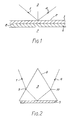
- FIG. 1 of the accompanying drawings Illustrated in Figure 1 of the accompanying drawings is a diagram of the equipment described in this paper.
- a beam 1 of light is applied from a laser source (not shown) onto an internal surface 2 of a glass body 3.
- a detector (not shown) monitors the internally reflected beam 4.
- Applied to the external surface 2 of glass body 3 is a thin film 5 of metal, for example gold or silver, and applied to the film 5 is a further thin film 6 of organic material containing antibodies.
- a sample 7 containing antigen is brought into contact with the antibody film 6 to thus cause a reaction between the antigen and the antibody. If binding occurs the refractive index of the layer 6 will change owing to the increased size of the antibody molecules and this change can be detected and measured using the surface plasmon resonance technique, as will now be explained.
- Surface plasmon resonance can be experimentally observed, in the arrangement of Figure 1, by varying the angle of the incident beam 1 and monitoring the intensity of the internally reflected beam 4. At a certain angle of incidence the parallel component of the light momentum will match with the dispersion for surface plasmons at the opposite surface 8 of the metal film. Provided that the thickness of metal film 5 is chosen correctly there will be an electromagnetic coupling between the glass/metal interface at surface 2 and the metal/antibody interface at surface 8 which results in surface plasmon resonance and thus an attenuation in the reflected beam 4 at that particular angle of incidence. Thus, as the angle of incidence of beam 1 is varied, surface plasmon resonance is observed as a sharp dip in the intensity of the internally reflected beam 4 at a particular angle of incidence.
- the angle of incidence at which resonance occurs is affected by the refractive index of the material against the metal film 5 - i.e. the antibody layer 6 - and the angle of incidence corresponding to resonance is thus a direct measure of the state of the reaction between the antibody and the antigen.
- Increased sensitivity can be obtained by choosing an angle of incidence half way down the reflectance dip curve, where the response is substantially linear, at the beginning of the antibody/antigen reaction, and then maintaining that angle of incidence fixed and observing changes in the intensity of the reflected beam 4 with time.
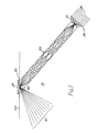
- FIG. 1 A diagram showing this arrangement is given in Figure 2 which is simply an experimental set up intended to demonstrate surface plasmon resonance.
- the prism is shown under reference 8 and has applied to its undersurface a thin film 5 of metal.
- Light 1 from a laser source (not shown) is incident on the prism where it is refracted at point 9 before entering the prism.
- the internally reflected beam 4 is likewise refracted (at point 10) upon exiting from the prism.
- a sensor for use in biological, biochemical or chemical testing comprising an optical waveguide having an input end and an output end, a source of electromagnetic radiation whose output is applied to the input end of said optical waveguide, and wherein said output end of the optical wavguide is cut off at an angle to its axis to provide a sloping end face, means for monitoring the radiation from said source which is internally reflected at said face, a layer of metallic material applied to said sloping face, a layer of sensitive material applied to the metallic layer, and means for introducing onto the sensitive layer so as to react therewith a sample to be analysed, the arrangement being such that the radiation incident at said face of the optical waveguide causes surface plasmon resonance to occur, the characteristics of which resonance, as detected by said monitoring means, is dependent upon the reaction between the sample and the sensitive layer.
- the radiation is in the visible or near-visible region, and this will be assumed throughout the present specification.
- optical waveguide as used herein is intended to cover any transmission line for electromagnetic radiation within or near the optical range, and in which the wave propagates along the waveguide by means of repeated internal reflections off the wall of waveguide.
- waveguides include the well-known fibre optic, on which the remainder of the present specification concentrates, but may also include rectangular section waveguides such as microscope slides along which, from edge to edge, light may be transmitted by means of repeated interval reflections off the major surfaces of the slide.
- Fibre optics rely for transmission of light on repeated internal reflections at the walls of the fibre, the light taking a zig-zag course as it proceeds along the fibre.
- fibre optics may be clad with a material having a lower refractive index than that of the material of the fibre.
- the fibre itself is made from glass, and the cladding of plastics material having a lower refractive index.
- the fibre In order to mechanically support the fibre, it is preferred that the fibre be embedded in a block of transparent material. It is necessary that the material be transparent in order to allow it to pass light internally reflected at the sloping end of the fibre optic and which thus emerges from the fibre optic to be intercepted by the monitoring means. If the refractive index of the material of the block is chosen suitably, it can act in place of the cladding in ensuring internal reflections along the walls of the fibre optic. This can be useful where the integrity of the cladding is suspect, or where the cladding is not present at all.
- the radiation source may incorporate means for focussing the radiation (i.e. light) onto the input end face of the fibre optic.
- the characteristics of the fibre optic are such that the sloping output face becomes illuminated with a range of angles of the input light.
- the input beam effectively becomes several beams incident upon the glass/metal interface over a range of angles.
- the equipment can be chosen so that the range of angles spans the angle of dip corresponding to surface plasmon resonance.
- the corresponding internally reflected beam is likewise effectively several beams and may be monitored by a large area detector, or by an array of angularly spaced detectors positioned to collect the whole emergent beam.
- the detectors can encode the information from the whole of the dip within milliseconds.
- the focussing means focusses the radiation onto the output surface of the fibre optic - in other words, onto the glass/metal interface.
- the input beam effectively spans a range of input angles which can be simultaneously monitored as described above.
- the layer applied to the metal film is assumed herein to be an antibody layer for use in immunoassays, it will be seen that any sensitive layer whose refractive index changes upon an event occurring can be used to thus provide a sensitive detector having a wide variety of applications in the fields of biology, biochemistry and chemistry.
- the antibody could be replaced with other analyte specific binding entities such as DNA probes.
- the metal film material is commonly silver or gold, usually applied by evaporation.
- the film needs to be as uniform as possible in order to cater for minute movement in the point of incidence of the incoming beam. It is assumed that a structured metal film will give the best resonance and there are various ways in which the glass body can be pretreated to improve the performance of the metal film and in particular to control the natural tendency of such films to form discontinuous islands:-
- Coating performance can also be improved by:-
- the apparatus comprises a casing 11 carrying a laser diode and lens assembly 12 and a large area imaging detector 13 such as a diode array, charge couple device (ccd) or similar.
- the source produces a collimated input beam of electromagnetic radiation.
- the frequency of the radiation must be such as to result in the generation of surface plasmon waves and in practice will be within or near the visible region.
- Suitable sources include an infra red diode laser, but an ordinary light source, such as an LED (light emitting diode), with suitable filters and collimators, could be used.
- the diode and lens assembly 12 is situated to one side of a well 14 formed in the top surface of the casing 11.
- This well is adapted to receive and locate a disposable test assembly built around a block 15 of radiation transparent material.
- the upper portion of the block is formed in the shape of a shallow tray having sides 16, and which contains three circular discs arranged one on top of another.
- the lowermost disc 17 is made of absorbent material and has a central through-aperture defining an active zone 18.
- the upper disc 19 has a central aperture intended to define a well 20 into which a sample to be tested is placed.
- the middle disc 21 has a central aperture 22 which is of a size to cause liquid in well 20 to travel through by capillary action into the active zone 18.
- the lower portion of the block 15 is shaped to locate securely into the wall 14.
- the lower portion has cast or moulded therein a fibre optic 23 which extends from the output of the laser diode and lens assembly 12 to the surface 24.
- the output end of the fibre optic is cut off at an angle to define a sloping exit face which is substantially coplanar with the surface 24 of the block 15. This sloping exit face can be seen more clearly in Figures 4 and 5.
- the exit face is ground and polished for maximum accuracy.
- the fibre optic is made of transparent material such as glass or plastics material which has a refractive index less than that of the surrounding block 15.
- the refractive index of the material of the block should be the same as or less than that of the cladding. If the cladding is suspect, a lower refractive index is best, as this ensures the internal reflections necessary for the light to travel along the fibre optic.
- a metal film layer 25 for example of silver, on top of which is applied a further layer 26 of a sensitive material whose refractive index changes as the test progresses.
- the sensitive layer 26 may for example be an antibody layer.
- the thickness of the metal layer 25 is such as to maximise the surface plasmon resonance reflectance dip when coated with the sensitive layer 26 and immersed in a typical test light from well 20 - e.g. serum.
- the layers 25 and 26 are kept small in area, restricted in fact to the area of the sloping exit face of the fibre optic.
- the diameter of the fibre optic is typically 100 microns, but can span a large range of diameters depending on the application. Diameters less than 10 microns are not normally used because of increased difficulty in coupling light into the fibre optic. However, these lower diameters could be used if special coupling techniques are employed, such as wedge or grating couplers.
- a sample to be tested and containing an antigen capable of binding with the antibody molecules in layer 26 is placed in the well 20 and passes through aperture 22 by capillary action. Emerging from aperture 22, the liquid sample commences to flow radially outwards in all directions towards the absorbent disc 17, passing as it does so the antibody layer 26. The sample adjacent the layer 26 is thus being constantly replenished during the course of the test, which ensures maximum sensitivity.
- any antigen within the sample capable of binding with the antibody in layer 26 will do so, thus altering the refractive index of layer 26 as the reaction proceeds.
- This change in refractive index is continuously monitored during the test by directing along the fibre optic 23 the light beam from assemble 12. Provided that conditions are correct - in particular the angle of incidence at the point of incidence on the fibre optic exit face is correct - the application of the light will result in the generation of a plasmon wave, thus extracting energy from the input beam and causing an attenuation in the intensity of the output beam at a particular angle of incidence.
- the input beam is arranged such that the mid-angle of the range of angles of the input beam is approximately half-way down the reflectance dip, as described above, and the test is carried out at a constant angle of incidence, monitoring the intensity of the reflected beam above and below this mid point level. This gives a linear and highly sensitive output.
- the initial reflectance dip which is chosen for setting up the angle of incidence should be the dip which results when some neutral or buffer solution is passed through the cell, or when the sample under test is passed through the cell but before any reaction thereof has taken place.
- the refractive index does not start to change immediately due to the antibody/antigen reaction. There is thus sufficient time to take an initial reading with the unreacted sample flowing past, which reading can be utilised, using feedback circuitry, to rapidly adjust the angle of incidence to an appropriate value half way down the reflectance dip so that the rest of the test can be performed at this fixed angle.
- the diode and lens assembly 12 is such as to provide an incident light beam 30 which is brought to a focus at the surface 24 - i.e. on the sloping exit face of the fibre optic.
- the incident light beam thus covers a range of input angles which can be arranged to cover the angles of incidence which are known to produce the dip in the internally reflected beam, or to cover that part of the dip - for example just one side thereof - which is to be used for measurement.
- the internally reflected beam shown under reference 31, is divergent and escapes from the fibre optic due to its large angle of incidence with the wall of the fibre optic. After leaving the fibre optic the reflected beam travels through the cladding, if any, and thence into the material of block 15. Due to the different refractive indices, there is bound to be some refraction of the beam, but this should be fairly minimal. Any such refraction can to a certain extent be compensated for as the reflected beam emerges from the block 15 into the air space within the casing 11. To this end the window 27 can be shaped such as shown in Figure 4.
- the reflected beam leaving window 27 is intercepted by the detector 13 which gives an output signal for analysis by external circuitry (not shown).
- the diode and lens assembly 13 is such as to provide a light beam 32 focussed onto the input face 33 of the fibre optic 23.
- Figure 5 also shows, by way of illustration, the use of a clad fibre optic, the layer 34 of cladding being of a material having a lower refractive index than that of the fibre optic itself.
- the dotted lines, reference 35 show the multiple reflection progress of the beam down the fibre optic until it reaches the sloping exit surface. Here, internal reflection takes place and an output beam 36 results. This latter beam passes through the cladding, thence through the block 15 into the interior of the casing 11 where it is intercepted by the detector 13, as before.
- the angle of the input beam is chosen to suit the circumstances; the dotted lines 37 represent the largest limit of the input angle beyond which internal reflection at the walls of the fibre optic will not take place, and transmission along the fibre optic is not possible.
- the input light beam takes the form of a series of separate, spaced coaxial beams 38 of annular section.
- a composite beam can be produced, for example, by sputtering rings of obscuration, coaxial with a solid input light beam (not shown), onto a transparent plate (not shown) onto which the solid beam is incident at right angles.
- Figure 6 shows a diagram of the ray paths of a composite beam such as described above along a fibre optic 23.
- the composite beam is first brought to a focus at the input face 33 of the fibre optic by means of a suitable lens 39.
- lens 39 will be a circular lens, for planar optics (such as the above-mentioned microscope slide), a cylindrical lens will be used.
- the front face of the lens 39 is coated with emulsion in a pattern of concentric rings coaxial with the lens axis.
- Increment of gradient refers to the tangent of the angle of the incoming beam relative to the axis, converted into a gradient.
- the distance d is 20 mm. It will be seen that the exact distance d is dependent upon the number of separate annular input beams - the greater the number, the greater the distance.
- the sloping exit face of the fibre optic is formed at such a position that it passes through the focal point 40 (or any of the later focal points, if a long fibre optic is required).
- the resultant divergent output beam 41 which passes into the block 15 is directed, as previously, to the detector 13.
- the advantage of this arrangement is that, because at the point of internal reflection on the sloping exit face the incident beams are brought to a focus, the size of the active zone is kept to a minimum, thus reducing errors caused by irregularities in the layers 25 and 26.
- the block 15 incorporates more than one fibre optic 23, each of these latter being illuminated with a common light source, or separate light sources.
- Each of these extra fibre optics terminate in a sloping exit face coplanar with surface 24 and spaced from adjacent fibre optics, and are covered with a metal layer 25 and sensitive layer 26, as before.
- the fibre optic is replaced by a plate of transparent material such as plastics or glass - a microscope slide will be suitable.
- One edge of the sheet is formed with said sloping exit face, and the light is inputted into the opposite edge.
- the use of the fibre optic to couple the light to the surface at which plasmon resonance takes place enables the area of the active zone to be minimised which reduces errors due to discontinuities in the metal and antibody films. In addition to this the physical size of the expensive antibody film is kept to a minimum.
- the system lends itself to mass production, and the fibre itself and its associated components should be cheap enough to be disposable, in the manner described above.
- the fibre optic 23 is shown as being straight, there is no reason why a curved fibre optic could not be used if the physical constraints of the apparatus require it. For example, in a multiple-fibre apparatus where each fibre optic is illuminated with a separate light source, it may be found more convenient to use curved fibre optics from the (relatively large) light sources to the (relatively closely spaced)-active zones.
- the refractive indices of the block 15 and fibre 23 must be chosen with some regard to the quality of the surface plasmon resonance which results: in particular, we are looking for a steep slope on at least one side of resonance, or preferably on both sides since then the slopes can be algebraically added to give a higher amplitude output signal, and thus an improved signal to noise ratio.
- the refractive index of the fibre is chosen in relation to that of the sensitive layer 26 immersed in typical sample fluid to give a good resonance; the refractive index of block 15 is thence chosen in relation to that of the fibre to give the required optical properties.
Abstract
Description
- This invention relates to sensors for use in biological, biochemical and chemical testing and in particular to immunosensors used to monitor the interaction of antibodies with their corresponding antigens.
- When antibodies are immobilised on a surface, the properties of the surface change when a solution containing a corresponding antigen is brought into contact with the surface to thus allow the antigen to bind with the antibody. In particular, the change in the optical properties of the surface can be monitored with suitable apparatus.
- The phenomenon of surface plasmon resonance (SPR) can be used to detect minute changes in the refractive index of the surface as the reaction between the antigen and the antibody proceeds. Surface plasmon resonance is the oscillation of the plasma of free electrons which exists at a metal boundary. These oscillations are affected by the refractive index of the material adjacent the metal surface and it is this that forms the basis of the sensor mechanism. Surface plasmon resonance may be achieved by using the evanescent wave which is generated when a light beam is totally internally reflected at the boundary of a medium, e.g. glass, which has a high dielectric constant. A paper describing the technique has been published under the title "Surface plasmon resonance for gas detection and biosensing" by Lieberg, Nylander and Lundstrom in Sensors and Actuators, Vol. 4, page 299. Illustrated in Figure 1 of the accompanying drawings is a diagram of the equipment described in this paper. A beam 1 of light is applied from a laser source (not shown) onto an internal surface 2 of a glass body 3. A detector (not shown) monitors the internally reflected
beam 4. Applied to the external surface 2 of glass body 3 is athin film 5 of metal, for example gold or silver, and applied to thefilm 5 is a furtherthin film 6 of organic material containing antibodies. A sample 7 containing antigen is brought into contact with theantibody film 6 to thus cause a reaction between the antigen and the antibody. If binding occurs the refractive index of thelayer 6 will change owing to the increased size of the antibody molecules and this change can be detected and measured using the surface plasmon resonance technique, as will now be explained. - Surface plasmon resonance can be experimentally observed, in the arrangement of Figure 1, by varying the angle of the incident beam 1 and monitoring the intensity of the internally reflected
beam 4. At a certain angle of incidence the parallel component of the light momentum will match with the dispersion for surface plasmons at the opposite surface 8 of the metal film. Provided that the thickness ofmetal film 5 is chosen correctly there will be an electromagnetic coupling between the glass/metal interface at surface 2 and the metal/antibody interface at surface 8 which results in surface plasmon resonance and thus an attenuation in thereflected beam 4 at that particular angle of incidence. Thus, as the angle of incidence of beam 1 is varied, surface plasmon resonance is observed as a sharp dip in the intensity of the internally reflectedbeam 4 at a particular angle of incidence. The angle of incidence at which resonance occurs is affected by the refractive index of the material against the metal film 5 - i.e. the antibody layer 6 - and the angle of incidence corresponding to resonance is thus a direct measure of the state of the reaction between the antibody and the antigen. Increased sensitivity can be obtained by choosing an angle of incidence half way down the reflectance dip curve, where the response is substantially linear, at the beginning of the antibody/antigen reaction, and then maintaining that angle of incidence fixed and observing changes in the intensity of thereflected beam 4 with time. - Known systems of the type described with reference to Figure 1 utilise a prism as the glass body 3. A diagram showing this arrangement is given in Figure 2 which is simply an experimental set up intended to demonstrate surface plasmon resonance. The prism is shown under reference 8 and has applied to its undersurface a
thin film 5 of metal. Light 1 from a laser source (not shown) is incident on the prism where it is refracted at point 9 before entering the prism. The internally reflectedbeam 4 is likewise refracted (at point 10) upon exiting from the prism. - One problem with the prism is that, as the angle of incidence is changed, either by moving the source, or rotating the prism, or both, the point on surface 2 at which the incoming beam is incident moves. Because of inevitable variations in the
metal film 5 and thecoating 6 of antibody, the angle of incidence which results in resonance changes as this movement occurs, which in turn introduces a further variable factor into the measurement and thus makes comparisons between the initial, unbound, state and the bound state of theantibody layer 6 less accurate. In addition to this, the system shown in Figure 2 is not realistic for mass production, where cheap and readily disposable components are required. - According to the present invention there is provided a sensor for use in biological, biochemical or chemical testing, said sensor comprising an optical waveguide having an input end and an output end, a source of electromagnetic radiation whose output is applied to the input end of said optical waveguide, and wherein said output end of the optical wavguide is cut off at an angle to its axis to provide a sloping end face, means for monitoring the radiation from said source which is internally reflected at said face, a layer of metallic material applied to said sloping face, a layer of sensitive material applied to the metallic layer, and means for introducing onto the sensitive layer so as to react therewith a sample to be analysed, the arrangement being such that the radiation incident at said face of the optical waveguide causes surface plasmon resonance to occur, the characteristics of which resonance, as detected by said monitoring means, is dependent upon the reaction between the sample and the sensitive layer. Normally the radiation is in the visible or near-visible region, and this will be assumed throughout the present specification.
- The term "optical waveguide" as used herein is intended to cover any transmission line for electromagnetic radiation within or near the optical range, and in which the wave propagates along the waveguide by means of repeated internal reflections off the wall of waveguide. Examples of such waveguides include the well-known fibre optic, on which the remainder of the present specification concentrates, but may also include rectangular section waveguides such as microscope slides along which, from edge to edge, light may be transmitted by means of repeated interval reflections off the major surfaces of the slide.
- Fibre optics rely for transmission of light on repeated internal reflections at the walls of the fibre, the light taking a zig-zag course as it proceeds along the fibre. In order to ensure that such internal reflection takes place, fibre optics may be clad with a material having a lower refractive index than that of the material of the fibre. Commonly the fibre itself is made from glass, and the cladding of plastics material having a lower refractive index.
- In order to mechanically support the fibre, it is preferred that the fibre be embedded in a block of transparent material. it is necessary that the material be transparent in order to allow it to pass light internally reflected at the sloping end of the fibre optic and which thus emerges from the fibre optic to be intercepted by the monitoring means. If the refractive index of the material of the block is chosen suitably, it can act in place of the cladding in ensuring internal reflections along the walls of the fibre optic. This can be useful where the integrity of the cladding is suspect, or where the cladding is not present at all.
- The optics can be arranged in various different ways. For example, the radiation source may incorporate means for focussing the radiation (i.e. light) onto the input end face of the fibre optic. In these circumstances, the characteristics of the fibre optic are such that the sloping output face becomes illuminated with a range of angles of the input light. Thus the input beam effectively becomes several beams incident upon the glass/metal interface over a range of angles. The equipment can be chosen so that the range of angles spans the angle of dip corresponding to surface plasmon resonance. The corresponding internally reflected beam is likewise effectively several beams and may be monitored by a large area detector, or by an array of angularly spaced detectors positioned to collect the whole emergent beam. Thus the detectors can encode the information from the whole of the dip within milliseconds.
- An equivalent effect can be obtained by arranging that the focussing means focusses the radiation onto the output surface of the fibre optic - in other words, onto the glass/metal interface. Here again the input beam effectively spans a range of input angles which can be simultaneously monitored as described above.
- Although the layer applied to the metal film is assumed herein to be an antibody layer for use in immunoassays, it will be seen that any sensitive layer whose refractive index changes upon an event occurring can be used to thus provide a sensitive detector having a wide variety of applications in the fields of biology, biochemistry and chemistry. For example, the antibody could be replaced with other analyte specific binding entities such as DNA probes.
- The metal film material is commonly silver or gold, usually applied by evaporation. The film needs to be as uniform as possible in order to cater for minute movement in the point of incidence of the incoming beam. It is assumed that a structured metal film will give the best resonance and there are various ways in which the glass body can be pretreated to improve the performance of the metal film and in particular to control the natural tendency of such films to form discontinuous islands:-
- 1. Immersion in molten metal nitrates and other molten salts. This has the effect of introducing ions into the surface in a manner which can be structured and which can act as foci for island formation.
- 2. Ion bombardment of cold or hot glass to introduce nucleating sites. The removal of the more mobile ions has been demonstrated to reduce the thickness at which the evaporated film becomes continuous.
- 3. Electroless plating or electroplating over lightly evaporated films (0 to 100 angstroms thick). Electroless plated films survive to a greater thickness than evaporated films and could form more stable nuclei for subsequent coating.
- 4. Evaporating on to electroless plated films. The electroless plated films have a stronger tendency to an island structure and to bigger islands with greater spacing than evaporating films. This could be of advantage in tuning to light of a prescribed wavelength.
- Coating performance can also be improved by:-
- 1. Controlling the glass surface temperature during coating. Using a higher temperature substrate increases the islands' size and the spacing between them and conversely.
- 2. Evaporating in the presence of a magnetic or electrostatic field or electron emission device to control the ion content of the vapour stream. The state of charge of the substrate is known to affect the island structure.
- 3. Controlling the angle of incidence of the evaporated vapour stream relative to the glass surface. The mobility of the evaporated atoms and hence their ability to form bigger islands is greater when the momentum of the atoms relative to the glass surface is increased.
- In order that the invention may be better understood, an embodiment thereof will now be described by way of example only and with reference to the accompanying drawings in which:-
- Figures 1 and 2 are diagrams of known experimental arrangements for demonstrating the surface plasmon resonance effect;
- Figure 3 is a diagrammatic side view of an embodiment of a sensor according to the present invention;
- Figure 4 is a diagrammatic side view of part of the sensor of Figure 3, on a larger scale, showing an example of the path of the light rays;
- Figure 5 is a diagrammatic side view of part of the sensor of Figure 3, on a still larger scale, showing an alternative example of the path of the light rays;
- Figure 6 is a diagrammatic side view showing the propagation of annular beams of light along a fibre optic; and
- Figure 7 is a view similar to Figure 5, but illustrating the use of annular beams, such as in Figure 6.
- Referring to Figure 3, the apparatus comprises a
casing 11 carrying a laser diode andlens assembly 12 and a large area imaging detector 13 such as a diode array, charge couple device (ccd) or similar. The source produces a collimated input beam of electromagnetic radiation. The frequency of the radiation must be such as to result in the generation of surface plasmon waves and in practice will be within or near the visible region. Suitable sources include an infra red diode laser, but an ordinary light source, such as an LED (light emitting diode), with suitable filters and collimators, could be used. - The diode and
lens assembly 12 is situated to one side of a well 14 formed in the top surface of thecasing 11. This well is adapted to receive and locate a disposable test assembly built around ablock 15 of radiation transparent material. The upper portion of the block is formed in the shape of a shallowtray having sides 16, and which contains three circular discs arranged one on top of another. Thelowermost disc 17 is made of absorbent material and has a central through-aperture defining anactive zone 18. Theupper disc 19 has a central aperture intended to define a well 20 into which a sample to be tested is placed. Themiddle disc 21 has acentral aperture 22 which is of a size to cause liquid in well 20 to travel through by capillary action into theactive zone 18. - The lower portion of the
block 15 is shaped to locate securely into thewall 14. The lower portion has cast or moulded therein afibre optic 23 which extends from the output of the laser diode andlens assembly 12 to thesurface 24. The output end of the fibre optic is cut off at an angle to define a sloping exit face which is substantially coplanar with thesurface 24 of theblock 15. This sloping exit face can be seen more clearly in Figures 4 and 5. The exit face is ground and polished for maximum accuracy. - The fibre optic is made of transparent material such as glass or plastics material which has a refractive index less than that of the surrounding
block 15. Alternatively in the case of a clad fibre optic, the refractive index of the material of the block should be the same as or less than that of the cladding. If the cladding is suspect, a lower refractive index is best, as this ensures the internal reflections necessary for the light to travel along the fibre optic. - Applied to the sloping exit face of the fibre optic is a
metal film layer 25, for example of silver, on top of which is applied afurther layer 26 of a sensitive material whose refractive index changes as the test progresses. Thesensitive layer 26 may for example be an antibody layer. The thickness of themetal layer 25 is such as to maximise the surface plasmon resonance reflectance dip when coated with thesensitive layer 26 and immersed in a typical test light from well 20 - e.g. serum. - In order to reduce the effects of discontinuities in the
layers layers - As will be explained in more detail during operation of the equipment, light from the laser diode and lens assembly is coupled into the fibre optic and is internally reflected at the sloping exit face to emerge from the fibre optic into the material of
block 15, through which latter it travels before finally exiting through awindow 27 in the well 14 to ultimately impinge on the sensitive area of the detector 13. - In order to use the apparatus a sample to be tested, and containing an antigen capable of binding with the antibody molecules in
layer 26 is placed in the well 20 and passes throughaperture 22 by capillary action. Emerging fromaperture 22, the liquid sample commences to flow radially outwards in all directions towards theabsorbent disc 17, passing as it does so theantibody layer 26. The sample adjacent thelayer 26 is thus being constantly replenished during the course of the test, which ensures maximum sensitivity. - As the sample flows past the
layer 26 any antigen within the sample capable of binding with the antibody inlayer 26 will do so, thus altering the refractive index oflayer 26 as the reaction proceeds. This change in refractive index is continuously monitored during the test by directing along thefibre optic 23 the light beam from assemble 12. Provided that conditions are correct - in particular the angle of incidence at the point of incidence on the fibre optic exit face is correct - the application of the light will result in the generation of a plasmon wave, thus extracting energy from the input beam and causing an attenuation in the intensity of the output beam at a particular angle of incidence. The input beam is arranged such that the mid-angle of the range of angles of the input beam is approximately half-way down the reflectance dip, as described above, and the test is carried out at a constant angle of incidence, monitoring the intensity of the reflected beam above and below this mid point level. This gives a linear and highly sensitive output. - The initial reflectance dip which is chosen for setting up the angle of incidence should be the dip which results when some neutral or buffer solution is passed through the cell, or when the sample under test is passed through the cell but before any reaction thereof has taken place. In connection with the latter method, which is currently preferred, it is to be noted that, as sample begins to flow past the active zone
adjacent layer 26 the refractive index does not start to change immediately due to the antibody/antigen reaction. There is thus sufficient time to take an initial reading with the unreacted sample flowing past, which reading can be utilised, using feedback circuitry, to rapidly adjust the angle of incidence to an appropriate value half way down the reflectance dip so that the rest of the test can be performed at this fixed angle. - With particular reference to Figures 4 to 7, we now consider three ways of optically operating the equipment. in the first way, shown in Figure 4, the diode and
lens assembly 12 is such as to provide anincident light beam 30 which is brought to a focus at the surface 24 - i.e. on the sloping exit face of the fibre optic. The incident light beam thus covers a range of input angles which can be arranged to cover the angles of incidence which are known to produce the dip in the internally reflected beam, or to cover that part of the dip - for example just one side thereof - which is to be used for measurement. - The internally reflected beam, shown under
reference 31, is divergent and escapes from the fibre optic due to its large angle of incidence with the wall of the fibre optic. After leaving the fibre optic the reflected beam travels through the cladding, if any, and thence into the material ofblock 15. Due to the different refractive indices, there is bound to be some refraction of the beam, but this should be fairly minimal. Any such refraction can to a certain extent be compensated for as the reflected beam emerges from theblock 15 into the air space within thecasing 11. To this end thewindow 27 can be shaped such as shown in Figure 4. - The reflected
beam leaving window 27 is intercepted by the detector 13 which gives an output signal for analysis by external circuitry (not shown). - In the alternative arrangement, shown in Figure 5, the diode and lens assembly 13 is such as to provide a
light beam 32 focussed onto theinput face 33 of thefibre optic 23. Figure 5 also shows, by way of illustration, the use of a clad fibre optic, thelayer 34 of cladding being of a material having a lower refractive index than that of the fibre optic itself. - The dotted lines,
reference 35, show the multiple reflection progress of the beam down the fibre optic until it reaches the sloping exit surface. Here, internal reflection takes place and anoutput beam 36 results. This latter beam passes through the cladding, thence through theblock 15 into the interior of thecasing 11 where it is intercepted by the detector 13, as before. - The angle of the input beam is chosen to suit the circumstances; the dotted
lines 37 represent the largest limit of the input angle beyond which internal reflection at the walls of the fibre optic will not take place, and transmission along the fibre optic is not possible. - In a further alternative arrangement, shown in Figure 7, the input light beam takes the form of a series of separate, spaced
coaxial beams 38 of annular section. Such a composite beam can be produced, for example, by sputtering rings of obscuration, coaxial with a solid input light beam (not shown), onto a transparent plate (not shown) onto which the solid beam is incident at right angles. - Before discussing the Figure 7 arrangement in detail, reference will be made to Figure 6 which shows a diagram of the ray paths of a composite beam such as described above along a
fibre optic 23. The composite beam is first brought to a focus at theinput face 33 of the fibre optic by means of asuitable lens 39. For the fibre optic shown,lens 39 will be a circular lens, for planar optics (such as the above-mentioned microscope slide), a cylindrical lens will be used. The front face of thelens 39 is coated with emulsion in a pattern of concentric rings coaxial with the lens axis. This produces, from a solid input beam, a series of concentric coaxial ring-section beams - note that, for the sake of explanation, the inputbeam entering lens 39 is shown as already divided into separated ring-section beams. The number of rings of emulsion, and hence the number of separate annular beams generated, will be dictated by the required angular definition at the detector 13. In a typical arrangement, with a lens diameter of 2 cm and a fibre optic diameter of 1 mm, the number of rings would typically be 256. - As the light propagates into the material of the fibre optic it internally reflects off the fibre optic walls in the manner described above, and takes up a distinct pattern, as illustrated. in particular, it will be noted that, at a
point 40 along the fibre optic, the separate beams making up the composite input beam come to a focus. Beyond thefocal point 40, the ray pattern repeats itself and will thus result in further focal points (not shown) along the fibre optic length. The distance d of the firstfocal point 40 from theinput face 33 is given by:-
- Increment of gradient refers to the tangent of the angle of the incoming beam relative to the axis, converted into a gradient. For example, for a typical 10 micron diameter fibre at 0.001 gradient, the distance d is 20 mm. It will be seen that the exact distance d is dependent upon the number of separate annular input beams - the greater the number, the greater the distance.
- In the arrangement of Figure 7, the sloping exit face of the fibre optic is formed at such a position that it passes through the focal point 40 (or any of the later focal points, if a long fibre optic is required). The resultant
divergent output beam 41 which passes into theblock 15 is directed, as previously, to the detector 13. - The advantage of this arrangement is that, because at the point of internal reflection on the sloping exit face the incident beams are brought to a focus, the size of the active zone is kept to a minimum, thus reducing errors caused by irregularities in the
layers - In a further embodiment of the invention (not shown), the
block 15 incorporates more than onefibre optic 23, each of these latter being illuminated with a common light source, or separate light sources. Each of these extra fibre optics terminate in a sloping exit face coplanar withsurface 24 and spaced from adjacent fibre optics, and are covered with ametal layer 25 andsensitive layer 26, as before. It will be seen that, by this means, several distinct active areas can be defined, at each of which an analysis of a common sample can be carried out. As well as carrying out multiple tests simultaneously on one sample, this arrangement enables reference tests to be set up. Alternatively, by providing separate sample feeding arrangements - i.e.separate wells 20 etc., - the same test can be carried out simultaneously on a number of different samples. - In a still further embodiment of the invention (not shown) the fibre optic is replaced by a plate of transparent material such as plastics or glass - a microscope slide will be suitable. One edge of the sheet is formed with said sloping exit face, and the light is inputted into the opposite edge. An advantage of using a sheet such as this is that multiple input beams can be applied to the input edge of the sheet and, if correctly adjusted, will propagate separately and independently along the sheet to the opposite edge. In conjunction with several distinct active areas, in the manner described above, this can enable simultaneous analysis of a number of different samples, or can enable a number of different tests (using, for example, different antibodies) to be carried out simultaneously on a common sample.
- The use of the fibre optic to couple the light to the surface at which plasmon resonance takes place enables the area of the active zone to be minimised which reduces errors due to discontinuities in the metal and antibody films. In addition to this the physical size of the expensive antibody film is kept to a minimum. The system lends itself to mass production, and the fibre itself and its associated components should be cheap enough to be disposable, in the manner described above.
- Although the
fibre optic 23 is shown as being straight, there is no reason why a curved fibre optic could not be used if the physical constraints of the apparatus require it. For example, in a multiple-fibre apparatus where each fibre optic is illuminated with a separate light source, it may be found more convenient to use curved fibre optics from the (relatively large) light sources to the (relatively closely spaced)-active zones. - The refractive indices of the
block 15 andfibre 23 must be chosen with some regard to the quality of the surface plasmon resonance which results: in particular, we are looking for a steep slope on at least one side of resonance, or preferably on both sides since then the slopes can be algebraically added to give a higher amplitude output signal, and thus an improved signal to noise ratio. Generally speaking the refractive index of the fibre is chosen in relation to that of thesensitive layer 26 immersed in typical sample fluid to give a good resonance; the refractive index ofblock 15 is thence chosen in relation to that of the fibre to give the required optical properties.
Claims (15)
Priority Applications (1)
| Application Number | Priority Date | Filing Date | Title |
|---|---|---|---|
| AT89300544T ATE67853T1 (en) | 1988-01-27 | 1989-01-20 | BIOLOGICAL DETECTION DEVICE. |
Applications Claiming Priority (2)
| Application Number | Priority Date | Filing Date | Title |
|---|---|---|---|
| GB888801807A GB8801807D0 (en) | 1988-01-27 | 1988-01-27 | Biological sensors |
| GB8801807 | 1988-01-27 |
Publications (2)
| Publication Number | Publication Date |
|---|---|
| EP0326291A1 true EP0326291A1 (en) | 1989-08-02 |
| EP0326291B1 EP0326291B1 (en) | 1991-09-25 |
Family
ID=10630614
Family Applications (1)
| Application Number | Title | Priority Date | Filing Date |
|---|---|---|---|
| EP89300544A Expired - Lifetime EP0326291B1 (en) | 1988-01-27 | 1989-01-20 | Biological sensors |
Country Status (9)
| Country | Link |
|---|---|
| US (1) | US5047213A (en) |
| EP (1) | EP0326291B1 (en) |
| JP (1) | JPH01224647A (en) |
| AT (1) | ATE67853T1 (en) |
| AU (1) | AU610975B2 (en) |
| CA (1) | CA1336650C (en) |
| DE (1) | DE68900277D1 (en) |
| GB (1) | GB8801807D0 (en) |
| WO (1) | WO1989007252A1 (en) |
Cited By (11)
| Publication number | Priority date | Publication date | Assignee | Title |
|---|---|---|---|---|
| EP0400061A1 (en) * | 1988-01-29 | 1990-12-05 | Fiberchem Inc | Fiber optic refractive index sensor using a metal clad. |
| WO1994000751A1 (en) * | 1992-06-29 | 1994-01-06 | Pharmacia Biosensor Ab | Improvement in optical assays |
| CH684132A5 (en) * | 1990-10-16 | 1994-07-15 | Suisse Electronique Microtech | Evanescent mode optical device for non-guided light signal |
| DE4305830C1 (en) * | 1993-02-26 | 1994-08-18 | Claus Dr Rer Nat Renschen | SPR sensor |
| US5359681A (en) * | 1993-01-11 | 1994-10-25 | University Of Washington | Fiber optic sensor and methods and apparatus relating thereto |
| US5812255A (en) * | 1994-07-13 | 1998-09-22 | Lau; Matthias | Process and device for determining the refractive index of different mediums |
| WO2000019203A1 (en) * | 1998-09-26 | 2000-04-06 | The Secretary Of State For Defence | Diagnostic method |
| DE10006083A1 (en) * | 2000-02-11 | 2001-08-23 | Inst Mikrotechnik Mainz Gmbh | Detecting layer thicknesses involves setting angle of incidence/frequency of electromagnetic radiation to produce surface plasmon resonance in metal layer |
| DE10126152C2 (en) * | 2001-05-30 | 2003-12-24 | Inst Mikrotechnik Mainz Gmbh | Spatially resolved ellipsometry method for the quantitative and / or qualitative determination of sample changes, biochip and measuring arrangement |
| WO2006005111A1 (en) * | 2004-07-08 | 2006-01-19 | Swinburne University Of Technology | Fibre sensor production |
| US7094595B2 (en) | 2000-10-30 | 2006-08-22 | Sru Biosystems, Inc. | Label-free high-throughput optical technique for detecting biomolecular interactions |
Families Citing this family (57)
| Publication number | Priority date | Publication date | Assignee | Title |
|---|---|---|---|---|
| US4935346A (en) | 1986-08-13 | 1990-06-19 | Lifescan, Inc. | Minimum procedure system for the determination of analytes |
| DE3909143A1 (en) * | 1989-03-21 | 1990-09-27 | Basf Ag | METHOD FOR EXAMINING SURFACE STRUCTURES |
| AU6354190A (en) * | 1989-08-21 | 1991-04-03 | Board Of Regents Of The University Of Washington, The | Multiple-probe diagnostic sensor |
| GB9015683D0 (en) * | 1990-07-17 | 1990-09-05 | Amersham Int Plc | Testing for metal ions |
| US5846708A (en) * | 1991-11-19 | 1998-12-08 | Massachusetts Institiute Of Technology | Optical and electrical methods and apparatus for molecule detection |
| US5327225A (en) * | 1993-01-28 | 1994-07-05 | The Center For Innovative Technology | Surface plasmon resonance sensor |
| US5395587A (en) * | 1993-07-06 | 1995-03-07 | Smithkline Beecham Corporation | Surface plasmon resonance detector having collector for eluted ligate |
| GB9320310D0 (en) * | 1993-10-01 | 1993-11-17 | Kodak Ltd | Production of carriers for surface plasmon resonance |
| GB9320305D0 (en) * | 1993-10-01 | 1993-11-17 | Kodak Ltd | Production of carriers for surface plasmin resonance |
| US5955153A (en) * | 1993-10-01 | 1999-09-21 | Johnson & Johnson Clinical Diagnostics, Inc. | Production of carriers for surface plasmon resonance |
| JPH0933427A (en) * | 1994-12-16 | 1997-02-07 | Toto Ltd | Biosensor and concentration measuring device therewith |
| US5591407A (en) * | 1995-04-21 | 1997-01-07 | American Research Corporation Of Virginia | Laser diode sensor |
| US5606633A (en) * | 1995-06-26 | 1997-02-25 | American Research Corporation Of Virginia | Chemical detector employing surface plasmon resonance excited using an optical waveguide configured as an asymmetric waveguide coupler |
| WO1997015820A1 (en) * | 1995-10-25 | 1997-05-01 | University Of Washington | Surface plasmon resonance electrode as chemical sensor |
| DE19611025A1 (en) * | 1996-03-20 | 1997-09-25 | Inst Chemo Biosensorik | Optical fiber optic sensor based on the resonant optical excitation of surface plasma waves |
| JPH09292334A (en) * | 1996-04-30 | 1997-11-11 | Fuji Photo Film Co Ltd | Surface plasmon sensor |
| US5846843A (en) * | 1996-11-18 | 1998-12-08 | The University Of Toledo | Sensor using long range surface plasmon resonance with diffraction double-grating |
| JPH10221249A (en) * | 1996-12-05 | 1998-08-21 | Norio Miura | Drug measuring device, sensor, and detecting element used for sensor |
| US5864641A (en) * | 1997-04-11 | 1999-01-26 | F&S, Inc. | Optical fiber long period sensor having a reactive coating |
| RU2141645C1 (en) | 1997-06-11 | 1999-11-20 | Никитин Петр Иванович | Method and device for examination of biological, biochemical and chemical characteristics of media |
| EP1443321A3 (en) * | 1997-09-10 | 2005-02-02 | Artificial Sensing Instruments ASI AG | Optical sensor and method for characterising a chemical and/or biochemical substance |
| RU2141644C1 (en) * | 1997-12-18 | 1999-11-20 | Коротков Константин Георгиевич | Method for determining energy-information impact of part under test on substance in liquid phase |
| US6368795B1 (en) | 1998-02-02 | 2002-04-09 | Signature Bioscience, Inc. | Bio-assay device and test system for detecting molecular binding events |
| US6395480B1 (en) | 1999-02-01 | 2002-05-28 | Signature Bioscience, Inc. | Computer program and database structure for detecting molecular binding events |
| US6338968B1 (en) | 1998-02-02 | 2002-01-15 | Signature Bioscience, Inc. | Method and apparatus for detecting molecular binding events |
| US6277651B1 (en) | 1998-07-09 | 2001-08-21 | Calspan Srl Corporation | Diode laser electrochemical sensor for detecting chemical and biological analytes |
| US6480282B1 (en) | 1999-05-06 | 2002-11-12 | University Of Washington | Capillary surface plasmon resonance sensors and multisensors |
| US7167615B1 (en) | 1999-11-05 | 2007-01-23 | Board Of Regents, The University Of Texas System | Resonant waveguide-grating filters and sensors and methods for making and using same |
| US6458326B1 (en) | 1999-11-24 | 2002-10-01 | Home Diagnostics, Inc. | Protective test strip platform |
| US7198939B2 (en) * | 2000-01-28 | 2007-04-03 | Agilent Technologies, Inc. | Apparatus for interrogating an addressable array |
| US7485454B1 (en) | 2000-03-10 | 2009-02-03 | Bioprocessors Corp. | Microreactor |
| JP2002022654A (en) * | 2000-07-11 | 2002-01-23 | Suzuki Motor Corp | Spr sensor plate and immunoreaction-measuring apparatus using the same |
| US20020086430A1 (en) * | 2000-12-28 | 2002-07-04 | Hopmeier Michael J. | Detection technology in agriculture operations |
| WO2002055993A2 (en) * | 2001-01-12 | 2002-07-18 | Univ Boston | Use of electrostatic fields to enhance surface plasmon resonance spectroscopy |
| US6525330B2 (en) | 2001-02-28 | 2003-02-25 | Home Diagnostics, Inc. | Method of strip insertion detection |
| US6541266B2 (en) | 2001-02-28 | 2003-04-01 | Home Diagnostics, Inc. | Method for determining concentration of an analyte in a test strip |
| JP2004527247A (en) * | 2001-04-10 | 2004-09-09 | バイオプロセッサーズ コーポレイション | Microfermentor devices and cell-based screening methods |
| US7329223B1 (en) * | 2001-05-31 | 2008-02-12 | Abbott Cardiovascular Systems Inc. | Catheter with optical fiber sensor |
| US7532920B1 (en) | 2001-05-31 | 2009-05-12 | Advanced Cardiovascular Systems, Inc. | Guidewire with optical fiber |
| US6697667B1 (en) | 2001-05-31 | 2004-02-24 | Advanced Cardiovascular Systems, Inc. | Apparatus and method for locating coronary sinus |
| US6716178B1 (en) | 2001-05-31 | 2004-04-06 | Advanced Cardiovascular Systems, Inc. | Apparatus and method for performing thermal and laser doppler velocimetry measurements |
| US7300798B2 (en) * | 2001-10-18 | 2007-11-27 | Agilent Technologies, Inc. | Chemical arrays |
| US6791690B2 (en) * | 2002-04-30 | 2004-09-14 | Agilent Technologies, Inc. | Reading dry chemical arrays |
| US20040009516A1 (en) * | 2002-05-08 | 2004-01-15 | Nelson Bryce P. | Arrayed SPR prism |
| DE60232689D1 (en) | 2002-12-25 | 2009-07-30 | Bio Rad Laboratories | Surface plasmon resonance SENSOR |
| JP4371954B2 (en) * | 2004-08-31 | 2009-11-25 | 富士フイルム株式会社 | Analysis method of test substance by surface plasmon resonance analysis |
| US20060227328A1 (en) * | 2005-04-08 | 2006-10-12 | Vanwiggeren Gregory D | Light-sensing system that uses light guides |
| US7749445B2 (en) | 2005-05-02 | 2010-07-06 | Bioscale, Inc. | Method and apparatus for analyzing bioprocess fluids |
| US7300631B2 (en) | 2005-05-02 | 2007-11-27 | Bioscale, Inc. | Method and apparatus for detection of analyte using a flexural plate wave device and magnetic particles |
| US7648844B2 (en) | 2005-05-02 | 2010-01-19 | Bioscale, Inc. | Method and apparatus for detection of analyte using an acoustic device |
| US7611908B2 (en) | 2005-05-02 | 2009-11-03 | Bioscale, Inc. | Method and apparatus for therapeutic drug monitoring using an acoustic device |
| WO2006130035A1 (en) * | 2005-06-01 | 2006-12-07 | Sergey Valentinovich Koltsov | Device for correcting an external electromagnetic field acting on a living organism an a method for the production thereof |
| US8509582B2 (en) * | 2005-08-30 | 2013-08-13 | Rambus Delaware Llc | Reducing light leakage and improving contrast ratio performance in FTIR display devices |
| US20080129980A1 (en) * | 2006-11-30 | 2008-06-05 | North Carolina State University | In-line fiber optic sensor devices and methods of fabricating same |
| US8354280B2 (en) | 2007-09-06 | 2013-01-15 | Bioscale, Inc. | Reusable detection surfaces and methods of using same |
| US11085878B2 (en) * | 2019-06-18 | 2021-08-10 | Eagle Technology, Llc | Radiation detection system with surface plasmon resonance detection and related methods |
| US11009611B2 (en) | 2019-06-18 | 2021-05-18 | Eagle Technology, Llc | Radiation detection system with surface plasmon resonance detection and related methods |
Citations (3)
| Publication number | Priority date | Publication date | Assignee | Title |
|---|---|---|---|---|
| GB2174802A (en) * | 1985-04-12 | 1986-11-12 | Plessey Co Plc | Optic-waveguide biosensor |
| EP0202021A2 (en) * | 1985-04-12 | 1986-11-20 | Plessey Overseas Limited | Optical assay: method and apparatus |
| GB2185308A (en) * | 1986-01-10 | 1987-07-15 | Stc Plc | Optical waveguide material sensor |
Family Cites Families (10)
| Publication number | Priority date | Publication date | Assignee | Title |
|---|---|---|---|---|
| USRE33064E (en) * | 1981-09-18 | 1989-09-19 | Prutec Limited | Method for the determination of species in solution with an optical wave-guide |
| CA1237645A (en) * | 1982-12-21 | 1988-06-07 | John H. Fisher | Assay technique |
| CA1261256A (en) * | 1984-06-13 | 1989-09-26 | Ian A. Shanks | Devices for use in chemical test procedures |
| US4775637A (en) * | 1984-12-10 | 1988-10-04 | Purtec Limited | An immunoassay apparatus having at least two waveguides and method for its use |
| JPS62220834A (en) * | 1986-03-24 | 1987-09-29 | Toshiba Corp | Photochemical analyzer |
| JPS62254040A (en) * | 1986-04-16 | 1987-11-05 | Daikin Ind Ltd | Immunity examination apparatus |
| GB8705650D0 (en) * | 1987-03-10 | 1987-04-15 | Pa Consulting Services | Assay technique |
| CA1321488C (en) * | 1987-08-22 | 1993-08-24 | Martin Francis Finlan | Biological sensors |
| US4909990A (en) * | 1987-09-02 | 1990-03-20 | Myron J. Block | Immunoassay apparatus |
| EP0341928A1 (en) * | 1988-05-10 | 1989-11-15 | AMERSHAM INTERNATIONAL plc | Improvements relating to surface plasmon resonance sensors |
-
1988
- 1988-01-27 GB GB888801807A patent/GB8801807D0/en active Pending
-
1989
- 1989-01-16 CA CA000588360A patent/CA1336650C/en not_active Expired - Fee Related
- 1989-01-18 US US07/299,564 patent/US5047213A/en not_active Expired - Fee Related
- 1989-01-20 AT AT89300544T patent/ATE67853T1/en not_active IP Right Cessation
- 1989-01-20 EP EP89300544A patent/EP0326291B1/en not_active Expired - Lifetime
- 1989-01-20 DE DE8989300544T patent/DE68900277D1/en not_active Expired - Fee Related
- 1989-01-26 AU AU28842/89A patent/AU610975B2/en not_active Ceased
- 1989-01-27 JP JP1019371A patent/JPH01224647A/en active Pending
- 1989-01-27 WO PCT/GB1989/000084 patent/WO1989007252A1/en unknown
Patent Citations (3)
| Publication number | Priority date | Publication date | Assignee | Title |
|---|---|---|---|---|
| GB2174802A (en) * | 1985-04-12 | 1986-11-12 | Plessey Co Plc | Optic-waveguide biosensor |
| EP0202021A2 (en) * | 1985-04-12 | 1986-11-20 | Plessey Overseas Limited | Optical assay: method and apparatus |
| GB2185308A (en) * | 1986-01-10 | 1987-07-15 | Stc Plc | Optical waveguide material sensor |
Non-Patent Citations (1)
| Title |
|---|
| SENSORS AND ACTUATORS, vol. 4, 1983, pages 299-304, Elsevier Sequoia S.A., Lausanne, CH; B. LIEDBERG et al.: "Surface plasmon resonance for gas detection and biosensing" * |
Cited By (18)
| Publication number | Priority date | Publication date | Assignee | Title |
|---|---|---|---|---|
| EP0400061A4 (en) * | 1988-01-29 | 1992-08-12 | Fiberchem, Inc. (A Delaware Corporation) | Fiber optic refractive index sensor using a metal clad |
| EP0400061A1 (en) * | 1988-01-29 | 1990-12-05 | Fiberchem Inc | Fiber optic refractive index sensor using a metal clad. |
| CH684132A5 (en) * | 1990-10-16 | 1994-07-15 | Suisse Electronique Microtech | Evanescent mode optical device for non-guided light signal |
| WO1994000751A1 (en) * | 1992-06-29 | 1994-01-06 | Pharmacia Biosensor Ab | Improvement in optical assays |
| US5641640A (en) * | 1992-06-29 | 1997-06-24 | Biacore Ab | Method of assaying for an analyte using surface plasmon resonance |
| US5835645A (en) * | 1993-01-11 | 1998-11-10 | University Of Washington | Fiber optic sensor and methods and apparatus relating thereto |
| US5359681A (en) * | 1993-01-11 | 1994-10-25 | University Of Washington | Fiber optic sensor and methods and apparatus relating thereto |
| US5647030A (en) * | 1993-01-11 | 1997-07-08 | University Of Washington | Fiber optic sensor and methods and apparatus relating thereto |
| DE4305830C1 (en) * | 1993-02-26 | 1994-08-18 | Claus Dr Rer Nat Renschen | SPR sensor |
| US5812255A (en) * | 1994-07-13 | 1998-09-22 | Lau; Matthias | Process and device for determining the refractive index of different mediums |
| WO2000019203A1 (en) * | 1998-09-26 | 2000-04-06 | The Secretary Of State For Defence | Diagnostic method |
| DE10006083A1 (en) * | 2000-02-11 | 2001-08-23 | Inst Mikrotechnik Mainz Gmbh | Detecting layer thicknesses involves setting angle of incidence/frequency of electromagnetic radiation to produce surface plasmon resonance in metal layer |
| DE10006083B4 (en) * | 2000-02-11 | 2004-01-22 | INSTITUT FüR MIKROTECHNIK MAINZ GMBH | Method for the quantitative and / or qualitative determination of layer thicknesses as well as a microreaction vessel and a titer plate |
| US7396684B2 (en) | 2000-02-11 | 2008-07-08 | Institut Fur Mikrotechnik Mainz Gmbh | Method for quantitatively and/or qualitatively detecting layer thicknesses, a microreaction vessel and titre plate |
| US7094595B2 (en) | 2000-10-30 | 2006-08-22 | Sru Biosystems, Inc. | Label-free high-throughput optical technique for detecting biomolecular interactions |
| US7118710B2 (en) | 2000-10-30 | 2006-10-10 | Sru Biosystems, Inc. | Label-free high-throughput optical technique for detecting biomolecular interactions |
| DE10126152C2 (en) * | 2001-05-30 | 2003-12-24 | Inst Mikrotechnik Mainz Gmbh | Spatially resolved ellipsometry method for the quantitative and / or qualitative determination of sample changes, biochip and measuring arrangement |
| WO2006005111A1 (en) * | 2004-07-08 | 2006-01-19 | Swinburne University Of Technology | Fibre sensor production |
Also Published As
| Publication number | Publication date |
|---|---|
| US5047213A (en) | 1991-09-10 |
| JPH01224647A (en) | 1989-09-07 |
| AU2884289A (en) | 1989-07-27 |
| ATE67853T1 (en) | 1991-10-15 |
| DE68900277D1 (en) | 1991-10-31 |
| WO1989007252A1 (en) | 1989-08-10 |
| AU610975B2 (en) | 1991-05-30 |
| GB8801807D0 (en) | 1988-02-24 |
| EP0326291B1 (en) | 1991-09-25 |
| CA1336650C (en) | 1995-08-15 |
Similar Documents
| Publication | Publication Date | Title |
|---|---|---|
| EP0326291B1 (en) | Biological sensors | |
| EP0305109B1 (en) | Biological sensors | |
| EP0341927B1 (en) | Biological sensors | |
| US6239876B1 (en) | Optical detector device | |
| US5055265A (en) | Biological sensors | |
| US5327225A (en) | Surface plasmon resonance sensor | |
| EP0343826B1 (en) | Biological sensors | |
| EP0205236B1 (en) | Improvements in or relating to optic-waveguide biosensors | |
| US5071248A (en) | Optical sensor for selective detection of substances and/or for the detection of refractive index changes in gaseous, liquid, solid and porous samples | |
| US5081012A (en) | Waveguide sensor with input and reflecting gratings and its use in immunoassay | |
| EP0478137A2 (en) | An optical sensor | |
| EP0548215A1 (en) | Biological sensors | |
| JPH06500636A (en) | Optical method for selectively detecting specific substances in chemical, biochemical, and biological measurement samples | |
| GB2185308A (en) | Optical waveguide material sensor | |
| FI84940B (en) | Sensor based on the surface plasma resonance phenomenon | |
| WO2000045154A1 (en) | Coupled mode optical sensor | |
| CA2497289A1 (en) | Biosensor | |
| France | Evanescent Field and Surface Plasmon Polaritons in Optical Sensors | |
| JP2003139692A (en) | Sensor utilizing total internal reflection attenuation |
Legal Events
| Date | Code | Title | Description |
|---|---|---|---|
| PUAI | Public reference made under article 153(3) epc to a published international application that has entered the european phase |
Free format text: ORIGINAL CODE: 0009012 |
|
| AK | Designated contracting states |
Kind code of ref document: A1 Designated state(s): AT BE CH DE FR GB IT LI LU NL SE |
|
| 17P | Request for examination filed |
Effective date: 19890905 |
|
| 17Q | First examination report despatched |
Effective date: 19910221 |
|
| GRAA | (expected) grant |
Free format text: ORIGINAL CODE: 0009210 |
|
| ITF | It: translation for a ep patent filed |
Owner name: BARZANO' E ZANARDO MILANO S.P.A. |
|
| AK | Designated contracting states |
Kind code of ref document: B1 Designated state(s): AT BE CH DE FR GB IT LI LU NL SE |
|
| REF | Corresponds to: |
Ref document number: 67853 Country of ref document: AT Date of ref document: 19911015 Kind code of ref document: T |
|
| REF | Corresponds to: |
Ref document number: 68900277 Country of ref document: DE Date of ref document: 19911031 |
|
| ET | Fr: translation filed | ||
| PLBE | No opposition filed within time limit |
Free format text: ORIGINAL CODE: 0009261 |
|
| STAA | Information on the status of an ep patent application or granted ep patent |
Free format text: STATUS: NO OPPOSITION FILED WITHIN TIME LIMIT |
|
| 26N | No opposition filed | ||
| EPTA | Lu: last paid annual fee | ||
| EAL | Se: european patent in force in sweden |
Ref document number: 89300544.7 |
|
| PGFP | Annual fee paid to national office [announced via postgrant information from national office to epo] |
Ref country code: LU Payment date: 19971215 Year of fee payment: 10 |
|
| PGFP | Annual fee paid to national office [announced via postgrant information from national office to epo] |
Ref country code: AT Payment date: 19980114 Year of fee payment: 10 |
|
| PGFP | Annual fee paid to national office [announced via postgrant information from national office to epo] |
Ref country code: BE Payment date: 19980320 Year of fee payment: 10 |
|
| PGFP | Annual fee paid to national office [announced via postgrant information from national office to epo] |
Ref country code: SE Payment date: 19990107 Year of fee payment: 11 |
|
| PGFP | Annual fee paid to national office [announced via postgrant information from national office to epo] |
Ref country code: FR Payment date: 19990111 Year of fee payment: 11 |
|
| PG25 | Lapsed in a contracting state [announced via postgrant information from national office to epo] |
Ref country code: LU Free format text: LAPSE BECAUSE OF NON-PAYMENT OF DUE FEES Effective date: 19990120 Ref country code: AT Free format text: LAPSE BECAUSE OF NON-PAYMENT OF DUE FEES Effective date: 19990120 |
|
| PGFP | Annual fee paid to national office [announced via postgrant information from national office to epo] |
Ref country code: GB Payment date: 19990121 Year of fee payment: 11 |
|
| PG25 | Lapsed in a contracting state [announced via postgrant information from national office to epo] |
Ref country code: BE Free format text: LAPSE BECAUSE OF NON-PAYMENT OF DUE FEES Effective date: 19990131 |
|
| PGFP | Annual fee paid to national office [announced via postgrant information from national office to epo] |
Ref country code: NL Payment date: 19990131 Year of fee payment: 11 |
|
| PGFP | Annual fee paid to national office [announced via postgrant information from national office to epo] |
Ref country code: DE Payment date: 19990201 Year of fee payment: 11 |
|
| PGFP | Annual fee paid to national office [announced via postgrant information from national office to epo] |
Ref country code: CH Payment date: 19990210 Year of fee payment: 11 |
|
| REG | Reference to a national code |
Ref country code: GB Ref legal event code: 732E |
|
| BERE | Be: lapsed |
Owner name: AMERSHAM INTERNATIONAL P.L.C. Effective date: 19990131 |
|
| PG25 | Lapsed in a contracting state [announced via postgrant information from national office to epo] |
Ref country code: GB Free format text: LAPSE BECAUSE OF NON-PAYMENT OF DUE FEES Effective date: 20000120 |
|
| PG25 | Lapsed in a contracting state [announced via postgrant information from national office to epo] |
Ref country code: SE Free format text: LAPSE BECAUSE OF NON-PAYMENT OF DUE FEES Effective date: 20000121 |
|
| PG25 | Lapsed in a contracting state [announced via postgrant information from national office to epo] |
Ref country code: LI Free format text: LAPSE BECAUSE OF NON-PAYMENT OF DUE FEES Effective date: 20000131 Ref country code: CH Free format text: LAPSE BECAUSE OF NON-PAYMENT OF DUE FEES Effective date: 20000131 |
|
| PG25 | Lapsed in a contracting state [announced via postgrant information from national office to epo] |
Ref country code: NL Free format text: LAPSE BECAUSE OF NON-PAYMENT OF DUE FEES Effective date: 20000801 |
|
| GBPC | Gb: european patent ceased through non-payment of renewal fee |
Effective date: 20000120 |
|
| EUG | Se: european patent has lapsed |
Ref document number: 89300544.7 |
|
| REG | Reference to a national code |
Ref country code: CH Ref legal event code: PL |
|
| PG25 | Lapsed in a contracting state [announced via postgrant information from national office to epo] |
Ref country code: FR Free format text: LAPSE BECAUSE OF NON-PAYMENT OF DUE FEES Effective date: 20000929 |
|
| NLV4 | Nl: lapsed or anulled due to non-payment of the annual fee |
Effective date: 20000801 |
|
| PG25 | Lapsed in a contracting state [announced via postgrant information from national office to epo] |
Ref country code: DE Free format text: LAPSE BECAUSE OF NON-PAYMENT OF DUE FEES Effective date: 20001101 |
|
| REG | Reference to a national code |
Ref country code: FR Ref legal event code: ST |
|
| REG | Reference to a national code |
Ref country code: FR Ref legal event code: TP Ref country code: FR Ref legal event code: CD |
|
| PG25 | Lapsed in a contracting state [announced via postgrant information from national office to epo] |
Ref country code: IT Free format text: LAPSE BECAUSE OF NON-PAYMENT OF DUE FEES;WARNING: LAPSES OF ITALIAN PATENTS WITH EFFECTIVE DATE BEFORE 2007 MAY HAVE OCCURRED AT ANY TIME BEFORE 2007. THE CORRECT EFFECTIVE DATE MAY BE DIFFERENT FROM THE ONE RECORDED. Effective date: 20050120 |