EP0326701A2 - Piezoelectric shockwaves source - Google Patents
Piezoelectric shockwaves source Download PDFInfo
- Publication number
- EP0326701A2 EP0326701A2 EP88121348A EP88121348A EP0326701A2 EP 0326701 A2 EP0326701 A2 EP 0326701A2 EP 88121348 A EP88121348 A EP 88121348A EP 88121348 A EP88121348 A EP 88121348A EP 0326701 A2 EP0326701 A2 EP 0326701A2
- Authority
- EP
- European Patent Office
- Prior art keywords
- piezo elements
- shock wave
- wave source
- membrane
- insulation
- Prior art date
- Legal status (The legal status is an assumption and is not a legal conclusion. Google has not performed a legal analysis and makes no representation as to the accuracy of the status listed.)
- Granted
Links
- 239000007788 liquid Substances 0.000 claims abstract description 13
- 238000009413 insulation Methods 0.000 claims abstract description 10
- 230000035939 shock Effects 0.000 claims description 20
- 239000012528 membrane Substances 0.000 claims description 18
- 230000008878 coupling Effects 0.000 claims description 13
- 238000010168 coupling process Methods 0.000 claims description 13
- 238000005859 coupling reaction Methods 0.000 claims description 13
- 239000002184 metal Substances 0.000 claims description 6
- 239000004020 conductor Substances 0.000 claims 1
- 210000004379 membrane Anatomy 0.000 description 18
- 239000000463 material Substances 0.000 description 5
- 239000011248 coating agent Substances 0.000 description 3
- 238000000576 coating method Methods 0.000 description 3
- 239000012774 insulation material Substances 0.000 description 3
- 240000005702 Galium aparine Species 0.000 description 1
- 208000000913 Kidney Calculi Diseases 0.000 description 1
- 206010029148 Nephrolithiasis Diseases 0.000 description 1
- 229910018503 SF6 Inorganic materials 0.000 description 1
- 230000001154 acute effect Effects 0.000 description 1
- 239000000853 adhesive Substances 0.000 description 1
- 238000004026 adhesive bonding Methods 0.000 description 1
- 230000001070 adhesive effect Effects 0.000 description 1
- 238000005266 casting Methods 0.000 description 1
- 150000001875 compounds Chemical class 0.000 description 1
- 238000005538 encapsulation Methods 0.000 description 1
- NBVXSUQYWXRMNV-UHFFFAOYSA-N fluoromethane Chemical compound FC NBVXSUQYWXRMNV-UHFFFAOYSA-N 0.000 description 1
- 208000001130 gallstones Diseases 0.000 description 1
- 239000012212 insulator Substances 0.000 description 1
- 238000004519 manufacturing process Methods 0.000 description 1
- 239000002480 mineral oil Substances 0.000 description 1
- 239000003921 oil Substances 0.000 description 1
- 238000004382 potting Methods 0.000 description 1
- 238000003825 pressing Methods 0.000 description 1
- 229920002545 silicone oil Polymers 0.000 description 1
- 238000005476 soldering Methods 0.000 description 1
- 239000007787 solid Substances 0.000 description 1
- 230000003595 spectral effect Effects 0.000 description 1
- SFZCNBIFKDRMGX-UHFFFAOYSA-N sulfur hexafluoride Chemical compound FS(F)(F)(F)(F)F SFZCNBIFKDRMGX-UHFFFAOYSA-N 0.000 description 1
- 229960000909 sulfur hexafluoride Drugs 0.000 description 1
- XLYOFNOQVPJJNP-UHFFFAOYSA-N water Substances O XLYOFNOQVPJJNP-UHFFFAOYSA-N 0.000 description 1
- 238000003466 welding Methods 0.000 description 1
Images

Classifications
-
- G—PHYSICS
- G10—MUSICAL INSTRUMENTS; ACOUSTICS
- G10K—SOUND-PRODUCING DEVICES; METHODS OR DEVICES FOR PROTECTING AGAINST, OR FOR DAMPING, NOISE OR OTHER ACOUSTIC WAVES IN GENERAL; ACOUSTICS NOT OTHERWISE PROVIDED FOR
- G10K15/00—Acoustics not otherwise provided for
- G10K15/04—Sound-producing devices
- G10K15/043—Sound-producing devices producing shock waves
-
- A—HUMAN NECESSITIES
- A61—MEDICAL OR VETERINARY SCIENCE; HYGIENE
- A61B—DIAGNOSIS; SURGERY; IDENTIFICATION
- A61B17/00—Surgical instruments, devices or methods, e.g. tourniquets
- A61B17/22—Implements for squeezing-off ulcers or the like on the inside of inner organs of the body; Implements for scraping-out cavities of body organs, e.g. bones; Calculus removers; Calculus smashing apparatus; Apparatus for removing obstructions in blood vessels, not otherwise provided for
- A61B17/225—Implements for squeezing-off ulcers or the like on the inside of inner organs of the body; Implements for scraping-out cavities of body organs, e.g. bones; Calculus removers; Calculus smashing apparatus; Apparatus for removing obstructions in blood vessels, not otherwise provided for for extracorporeal shock wave lithotripsy [ESWL], e.g. by using ultrasonic waves
-
- B—PERFORMING OPERATIONS; TRANSPORTING
- B06—GENERATING OR TRANSMITTING MECHANICAL VIBRATIONS IN GENERAL
- B06B—METHODS OR APPARATUS FOR GENERATING OR TRANSMITTING MECHANICAL VIBRATIONS OF INFRASONIC, SONIC, OR ULTRASONIC FREQUENCY, e.g. FOR PERFORMING MECHANICAL WORK IN GENERAL
- B06B1/00—Methods or apparatus for generating mechanical vibrations of infrasonic, sonic, or ultrasonic frequency
- B06B1/02—Methods or apparatus for generating mechanical vibrations of infrasonic, sonic, or ultrasonic frequency making use of electrical energy
- B06B1/06—Methods or apparatus for generating mechanical vibrations of infrasonic, sonic, or ultrasonic frequency making use of electrical energy operating with piezoelectric effect or with electrostriction
- B06B1/0607—Methods or apparatus for generating mechanical vibrations of infrasonic, sonic, or ultrasonic frequency making use of electrical energy operating with piezoelectric effect or with electrostriction using multiple elements
- B06B1/0622—Methods or apparatus for generating mechanical vibrations of infrasonic, sonic, or ultrasonic frequency making use of electrical energy operating with piezoelectric effect or with electrostriction using multiple elements on one surface
Definitions
- the invention relates to a piezoelectric shock wave source according to the preamble of claim 1.
- DE 34 25 992 - C2 discloses a piezoelectric shock wave source with the features of the preamble.
- the shock wave source is used only for non-invasive crushing of concrements in the bodies of living beings.
- the insulation between the piezo elements there (column 3, line 38) consists of a soft and electrically insulating casting compound.
- the object of the invention is to propose a shock wave source that generates stronger shock waves.
- Embodiments of the invention are the subject of subclaims.
- the liquid or gaseous insulation according to the invention enables a substantial increase in the dielectric strength.
- All known liquid can be used and gaseous insulation materials. Since these are always in direct contact with the piezo elements due to their physical state, the invention reliably prevents an air gap from forming, as with solid insulation materials, due to the mechanical movements, along which the voltage can discharge as a leakage current. According to the invention, the voltage - and thus the power - can be increased.
- All known liquid « (continue p. 2)
- Insulation materials such as fluorocarbonates or oils or the gaseous insulators such as sulfur hexafluoride or fluorocarbon.
- the shock wave source according to the invention can be designed with or without a membrane on the front of the piezo elements. If a membrane is used, it usually consists of a metal and at the same time serves to contact the piezo elements from the front.
- This front membrane can consist of a material of suitable acoustic impedance which, with a suitable layer thickness, meets the requirements of impedance matching between piezoceramic and coupling liquid (for example water or a gel).
- a suitable material is, for example, Mg Mn2 with the material number 3.5200 DIN 1729.
- the preferred layer thickness is ⁇ / 4, where ⁇ is the wavelength of the preferred spectral component of the acute pulse.
- the preferred wavelength depends on the material and the size of the calculus.
- the three figures each show sections from shock wave sources according to the invention.
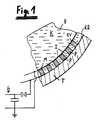
- FIG. 1 shows a shock wave source with the carrier T, which here has a spherical shape.
- the piezo elements P are arranged on the carrier T.
- the piezo elements are placed next to one another at a small distance and leave space for the insulation I.
- the contacts at the front and rear of the piezo elements P are provided at the front (KV) and rear (KB).
- the front contact KV is in this embodiment also as a membrane M made of metal executed.
- the rear contact KR is designed here as a conductive coating on the carrier T.
- In front of the membrane M is the coupling medium K, which is enclosed here, for example, in a coupling cushion B.
- the coupling medium K has the task of introducing the shock waves into the patient's body, not shown here, as losslessly as possible.
- the shock wave source shown is electrically connected so that the membrane M is at ground potential and a high-voltage pulse can be applied to the rear contact KR.
- This voltage pulse causes the piezo elements P to briefly contract or expand, which they pass on to the coupling liquid via the membrane M.
- This short-term pressure pulse combines at the focal point of the calotte to form the desired shock wave, the energy of which is sufficient to crush a concrement, for example a kidney stone or a gall stone.
- the insulation I is a liquid or a gas, which is enclosed here between the carrier T and the membrane M.
- FIG. 2 shows a further embodiment of a shock wave source according to the invention, in which the earthed membrane M has been dispensed with.
- the piezo elements P are again arranged on the carrier T.
- the front-side contacting KV is realized here using wire clips.
- the insulation I between the piezo elements P is at the same time the coupling liquid K which fills the coupling pad B. Silicone oils or mineral oils are particularly suitable as liquids.
- the embodiment of FIG. 2 has a particularly high output power due to the omission of the membrane M.
- FIG 3 shows an embodiment in which the rear Contact KR is taken from wire clips or from a conductive braid.
- the piezo elements are cast in a backing or potting on the back, which here acts as a carrier T.
- a metal membrane M At the front of the piezo elements there is a metal membrane M.
- the insulating liquid I or - not shown - the insulating gas In the spaces between the encapsulation T and the metal membrane M is the insulating liquid I or - not shown - the insulating gas.
Abstract
Description
Die Erfindung betrifft eine piezoelektrische Stosswellenquelle nach dem Oberbegriff des Anspruchs 1.The invention relates to a piezoelectric shock wave source according to the preamble of
Aus der DE 34 25 992 - C2 ist eine piezoelektrische Stosswellenquelle mit den Merkmalen des Oberbegriffs bekannt. Die Stosswellenquelle wird nur nichtinvasiven Zerkleinerung von Konkrementen in Körpern von Lebewesen eingesetzt. Die Isolierung zwischen den Piezoelementen besteht dort (Spalte 3, Zeile 38) aus einer weichen und elektrisch isolierenden Vergußmasse.DE 34 25 992 - C2 discloses a piezoelectric shock wave source with the features of the preamble. The shock wave source is used only for non-invasive crushing of concrements in the bodies of living beings. The insulation between the piezo elements there (column 3, line 38) consists of a soft and electrically insulating casting compound.
Aufgabe der Erfindung ist es, eine Stosswellenquelle vorzuschlagen, die stärkere Stosswellen erzeugt.The object of the invention is to propose a shock wave source that generates stronger shock waves.
Diese Aufgabe wird erfindungsgemäss mit einer piezoelektrischen Stosswellenquelle mit den Merkmalen des Anspruchs 1 gelöst.This object is achieved according to the invention with a piezoelectric shock wave source with the features of
Ausführungen der Erfindung sind Gegenstände von Unteransprüchen.Embodiments of the invention are the subject of subclaims.
Die erfindungsgemässe flüssige oder gasförmige Isolierung ermöglicht eine wesentliche Erhöhung der elektrischen Spannungsfestigkeit. Verwendbar sind alle bekannten flüssigen und gasförmigen Isolationsmaterialien. Da diese durch ihren Aggregatzustand bedingt stets direkt an den Piezoelementen anliegen wird durch die Erfindung zuverlässig verhindert, daß - wie bei festen Isolationsmaterialien - durch die mechanische Bewegungen sich ein Luftspalt bildet, längs dessen sich die Spannung als Kriechstrom entladen kann. Erfindungsgemäß kann die Spannung - und damit die Leistung - erhöht werden. Verwendbar sind alle bekannten flüssigen ......(weiter S. 2)The liquid or gaseous insulation according to the invention enables a substantial increase in the dielectric strength. All known liquid can be used and gaseous insulation materials. Since these are always in direct contact with the piezo elements due to their physical state, the invention reliably prevents an air gap from forming, as with solid insulation materials, due to the mechanical movements, along which the voltage can discharge as a leakage current. According to the invention, the voltage - and thus the power - can be increased. All known liquid ...... (continue p. 2)
Isolationsmaterialien, wie zum Beispiel Fluorcarbonate oder Oele oder die gasförmigen Isolatoren wie Schwefelhexafluorid oder Fluorcarbon.Insulation materials such as fluorocarbonates or oils or the gaseous insulators such as sulfur hexafluoride or fluorocarbon.
Die erfindungsgemässe Stosswellenquelle kann mit oder ohne Membran an der Vorderseite der Piezoelemente ausgeführt sein. Wird eine Membran verwendet, so besteht sie üblicherweise aus einem Metall und dient gleichzeitig zur vorderseitigen Kontaktierung der Piezoelemente. Diese vordere Membran kann aus einem Werkstoff geeigneter akustischer Impedanz bestehen, die bei geeigneter Schichtdicke die Forderungen der Impedanzanpassung zwischen Piezokeramik und Koppelflüssigkeit (zum Beispiel Wasser oder ein Gel) erfüllt. Ein geeigneter Werkstoff ist zum Beispiel Mg Mn2 mit der Werkstoffnummer 3.5200 DIN 1729. Der Werkstoff (2) der Membran sollte die Forderung:
Z = akustische Impedanz
Z₁ = akustische Impedanz des Piezoelements
Z₃ = akustische Impedanz des Koppelmediums.The shock wave source according to the invention can be designed with or without a membrane on the front of the piezo elements. If a membrane is used, it usually consists of a metal and at the same time serves to contact the piezo elements from the front. This front membrane can consist of a material of suitable acoustic impedance which, with a suitable layer thickness, meets the requirements of impedance matching between piezoceramic and coupling liquid (for example water or a gel). A suitable material is, for example, Mg Mn2 with the material number 3.5200 DIN 1729. The material (2) of the membrane should meet the requirement:
Z = acoustic impedance
Z₁ = acoustic impedance of the piezo element
Z₃ = acoustic impedance of the coupling medium.
Die bevorzugte Schichtdicke beträgt λ/4, wobei λ die Wellenlänge der bevorzugten Spektralkomponente des akutischen Impulses ist. Die bevorzugte Wellenlänge hänge vom Material und von der Grösse des Konkrements ab.The preferred layer thickness is λ / 4, where λ is the wavelength of the preferred spectral component of the acute pulse. The preferred wavelength depends on the material and the size of the calculus.
Möglich ist auch, dass vor jedem einzelnen Piezoelement ein geeigneter kleiner Körper zwecks Impedanzanpassung angeordnet ist.It is also possible that a suitable small body is arranged in front of each individual piezo element for the purpose of impedance matching.
Die elektrische Verbindung zwischen den Piezoelementen und (sofern vorhanden) der Metallmembran oder zwischen den Piezoelementen und der rückseitigen Kontaktierung (zum Beispiel einer leitfähigen Beschichtung auf dem Träger (Backing) kann durch
- a) Löten
- b) Verkleben mit leitfähigem Kleber
- c) Ultraschallschweißen oder
- d) einfaches Anpressen
In einer bevorzugten Ausführung kann für das Koppelmedium und die Isolierung die gleiche Flüssigkeit verwendet werden, wodurch die vorderseitige Membran überflüssig wird und die Leistung der Quelle nochmals gesteigert wird.The electrical connection between the piezo elements and (if present) the metal membrane or between the piezo elements and the contact on the rear (for example a conductive coating on the carrier (backing) can be achieved by
- a) Soldering
- b) Gluing with conductive adhesive
- c) ultrasonic welding or
- d) simple pressing
In a preferred embodiment, the same liquid can be used for the coupling medium and the insulation, as a result of which the front membrane is unnecessary and the performance of the source is increased again.
Die Erfindung wird anhand dreier Figuren näher erläutert.The invention is illustrated by three figures.
Die drei Figuren zeigen je Ausschnitte aus erfindungsgemässen Stosswellenquellen.The three figures each show sections from shock wave sources according to the invention.
Figur 1 zeigt eine Stosswellenquelle mit dem Träger T, der hier eine Kalottenform aufweist. Auf dem Träger T sind die Piezoelemente P angeordnet. Die Piezoelemente stehen im kleinen Abstand nebeneinander und lassen Platz für die Isolierung I. An der Vorderseite und der Rückseite der Piezoelemente P sind die Kontaktierungen vorne (KV) und hinten (KB) vorgesehen. Die vordere Kontaktierung KV ist in dieser Ausführungsführung gleichzeitig als Membran M aus Metall ausgeführt. Die hintere Kontaktierung KR ist hier als leitfähige Beschichtung auf den Träger T ausgeführt. Vor der Membran M befindet sich das Koppelmedium K, das hier zum Beispiel in einem Koppelkissen B eingeschlossen ist. Das Koppelmedium K hat die Aufgabe, die Stosswellen möglichst verlustlos in den hier nicht gezeichneten Körper des Patienten einzuleiten. Die gezeigte Stosswellenquelle ist elektrisch so geschaltet, dass die Membran M auf Erdpotential liegt und an die hintere Kontaktierung KR ein Hochspannungsimpuls angelegt werden kann. Dieser Spannungspuls veranlasst die Piezoelemente P zu einer kurzfristigen Kontraktion oder Ausdehnung, die diese über die Membran M an die Koppelflüssigkeit weitergeben. Dieser kurzfristige Druckpuls vereinigt sich im Brennpunkt der Kalotte zu der erwünschten Stosswelle, deren Energie ausreicht, ein Konkrement, zum Beispiel einen Nierenstein oder einen Gallenstein, zu zerkleinern. Erfindungsgemäss ist die Isolierung I eine Flüssigkeit oder ein Gas, das hier zwischen dem Träger T und der Membran M eingeschlossen ist.Figure 1 shows a shock wave source with the carrier T, which here has a spherical shape. The piezo elements P are arranged on the carrier T. The piezo elements are placed next to one another at a small distance and leave space for the insulation I. The contacts at the front and rear of the piezo elements P are provided at the front (KV) and rear (KB). The front contact KV is in this embodiment also as a membrane M made of metal executed. The rear contact KR is designed here as a conductive coating on the carrier T. In front of the membrane M is the coupling medium K, which is enclosed here, for example, in a coupling cushion B. The coupling medium K has the task of introducing the shock waves into the patient's body, not shown here, as losslessly as possible. The shock wave source shown is electrically connected so that the membrane M is at ground potential and a high-voltage pulse can be applied to the rear contact KR. This voltage pulse causes the piezo elements P to briefly contract or expand, which they pass on to the coupling liquid via the membrane M. This short-term pressure pulse combines at the focal point of the calotte to form the desired shock wave, the energy of which is sufficient to crush a concrement, for example a kidney stone or a gall stone. According to the invention, the insulation I is a liquid or a gas, which is enclosed here between the carrier T and the membrane M.
Figur 2 zeigt eine weitere Ausführung einer erfindungsgemässen Stosswellenquelle, bei der auf die geerdete Membran M verzichtet wurde. Die Piezoelemente P sind wieder auf dem Träger T angeordnet. Die vorderseitige Kontaktierung KV ist hier durch Drahtbügel realisiert. Die Isolierung I zwischen den Piezoelementen P ist gleichzeitig die Koppelflüssigkeit K, die das Koppelkissen B füllt. Als Flüssigkeit sind hier besonders Silikonöle oder Mineralöle geeignet.FIG. 2 shows a further embodiment of a shock wave source according to the invention, in which the earthed membrane M has been dispensed with. The piezo elements P are again arranged on the carrier T. The front-side contacting KV is realized here using wire clips. The insulation I between the piezo elements P is at the same time the coupling liquid K which fills the coupling pad B. Silicone oils or mineral oils are particularly suitable as liquids.
Die Ausführung der Figur 2 hat durch den Wegfall der Membran M eine besonders hohe Ausgangsleistung.The embodiment of FIG. 2 has a particularly high output power due to the omission of the membrane M.
Die Figur 3 zeigt eine Ausführung, bei der die rückwärtige Kontaktierung KR von Drahtbügeln oder von einem leitfähigen Geflecht übernommen wird. Die Piezoelemente sind in einem Backing oder Verguß auf der Rückseite eingegossen, der hier als Träger T fungiert. An der Vorderseite der Piezoelemente befindet sich hier eine Metallmembran M. In den Zwischenräumen zwischen dem Verguß T und der Metallmembran M befindet sich die isolierende Flüssigkeit I oder - nicht gezeigt - das isolierende Gas.Figure 3 shows an embodiment in which the rear Contact KR is taken from wire clips or from a conductive braid. The piezo elements are cast in a backing or potting on the back, which here acts as a carrier T. At the front of the piezo elements there is a metal membrane M. In the spaces between the encapsulation T and the metal membrane M is the insulating liquid I or - not shown - the insulating gas.
Claims (6)
- einer Vielzahl von Piezoelementen (P)
- einem Träger (T)
- Kontaktierungen (KR, KV) auf einer oder beiden Seiten der Piezoelemente
- einer Isolierung (I) zwischen den Piezoelementen (P) und
- einem Koppelmedium (K) zum Einleiten der Stosswellen in den Körper des Patienten,
dadurch gekennzeichnet, dass die Isolierung (I) flüssig oder gasförmig ist.1. Piezoelectric shock wave source for medical purposes with
- a variety of piezo elements (P)
- a carrier (T)
- Contacts (KR, KV) on one or both sides of the piezo elements
- An insulation (I) between the piezo elements (P) and
a coupling medium (K) for introducing the shock waves into the patient's body,
characterized in that the insulation (I) is liquid or gaseous.
Applications Claiming Priority (2)
| Application Number | Priority Date | Filing Date | Title |
|---|---|---|---|
| DE3803275 | 1988-02-04 | ||
| DE3803275A DE3803275A1 (en) | 1988-02-04 | 1988-02-04 | PIEZOELECTRIC SHOCK WAVE SOURCE |
Publications (3)
| Publication Number | Publication Date |
|---|---|
| EP0326701A2 true EP0326701A2 (en) | 1989-08-09 |
| EP0326701A3 EP0326701A3 (en) | 1989-11-02 |
| EP0326701B1 EP0326701B1 (en) | 1992-07-08 |
Family
ID=6346591
Family Applications (1)
| Application Number | Title | Priority Date | Filing Date |
|---|---|---|---|
| EP88121348A Expired - Lifetime EP0326701B1 (en) | 1988-02-04 | 1988-12-21 | Piezoelectric shockwaves source |
Country Status (5)
| Country | Link |
|---|---|
| US (1) | US5119801A (en) |
| EP (1) | EP0326701B1 (en) |
| JP (1) | JPH01223950A (en) |
| DE (2) | DE3803275A1 (en) |
| ES (1) | ES2034144T3 (en) |
Cited By (4)
| Publication number | Priority date | Publication date | Assignee | Title |
|---|---|---|---|---|
| EP0436809A2 (en) * | 1990-01-09 | 1991-07-17 | Richard Wolf GmbH | Ultrasonic transducer using piezoelectric elements |
| FR2679125A1 (en) * | 1991-07-19 | 1993-01-22 | Technomed Int Sa | USE OF AT LEAST ONE COMPOSITE PIEZOELECTRIC TRANSDUCER FOR THE MANUFACTURE OF AN ULTRASONIC THERAPY APPARATUS FOR THERAPY IN PARTICULAR OF CONCRETIONS, FABRICS OR BONES OF A LIVING BEING. |
| US5316000A (en) * | 1991-03-05 | 1994-05-31 | Technomed International (Societe Anonyme) | Use of at least one composite piezoelectric transducer in the manufacture of an ultrasonic therapy apparatus for applying therapy, in a body zone, in particular to concretions, to tissue, or to bones, of a living being and method of ultrasonic therapy |
| WO2001048181A2 (en) * | 1999-12-23 | 2001-07-05 | Dornier Medizintechnik Gmbh | Device for transferring molecules in cells |
Families Citing this family (64)
| Publication number | Priority date | Publication date | Assignee | Title |
|---|---|---|---|---|
| DE3807568A1 (en) * | 1988-03-08 | 1989-09-21 | Storz Karl Gmbh & Co | PIEZOELECTRIC SOUND TRANSMITTER FOR THERAPEUTIC APPLICATIONS |
| DE3940808A1 (en) * | 1989-12-09 | 1991-06-20 | Dornier Medizintechnik | Surgical ultrasonic piezoelectric transducer array - uses array of ultrasonic generators to enable independent excitation of beam focused at kidney stone |
| DE4015605A1 (en) * | 1990-05-15 | 1991-11-21 | Nied Roland | Production of particles smaller than 1 micro-metre - involves use of high velocity jets directed through suspension |
| US7189209B1 (en) | 1996-03-29 | 2007-03-13 | Sanuwave, Inc. | Method for using acoustic shock waves in the treatment of a diabetic foot ulcer or a pressure sore |
| US5866336A (en) * | 1996-07-16 | 1999-02-02 | Oncor, Inc. | Nucleic acid amplification oligonucleotides with molecular energy transfer labels and methods based thereon |
| US6117635A (en) * | 1996-07-16 | 2000-09-12 | Intergen Company | Nucleic acid amplification oligonucleotides with molecular energy transfer labels and methods based thereon |
| US6390995B1 (en) | 1997-02-12 | 2002-05-21 | Healthtronics Surgical Services, Inc. | Method for using acoustic shock waves in the treatment of medical conditions |
| US20070059752A1 (en) * | 1999-06-09 | 2007-03-15 | Biosearch Technologies, Inc. | Fluorescence energy transfer probes with stabilized conformations |
| US6596490B2 (en) | 2000-07-14 | 2003-07-22 | Applied Gene Technologies, Inc. | Nucleic acid hairpin probes and uses thereof |
| US6380377B1 (en) | 2000-07-14 | 2002-04-30 | Applied Gene Technologies, Inc. | Nucleic acid hairpin probes and uses thereof |
| NZ528348A (en) * | 2001-02-27 | 2007-07-27 | Virco Bvba | Circular probe amplification (CPA) using closed circular padlock probe molecules and energy-transfer primers |
| WO2003024923A1 (en) * | 2001-09-14 | 2003-03-27 | Axys Pharmaceuticals, Inc. | Sulfonamide compounds as protease inhibitors |
| JP4384603B2 (en) | 2002-06-26 | 2009-12-16 | コールド スプリング ハーバー ラボラトリー | Methods and compositions for measuring methylation profiles |
| US20040009482A1 (en) * | 2002-07-09 | 2004-01-15 | Nanibhushan Dattagupta | Compositions and methods for detecting streptococcus agalactiae surface immunogenic protein genes |
| US20040009574A1 (en) * | 2002-07-09 | 2004-01-15 | Nanibhushan Dattagupta | Compositions and methods for detecting streptococcus agalactiae capsular polysaccharide synthesis genes |
| US20060073475A1 (en) * | 2002-08-09 | 2006-04-06 | Nanibhushan Dattagupta | Compositions and methods for detecting pathogenic bacteria expressing chaperonin proteins |
| US20040162508A1 (en) * | 2003-02-19 | 2004-08-19 | Walter Uebelacker | Shock wave therapy method and device |
| US20060100549A1 (en) * | 2004-10-22 | 2006-05-11 | Reiner Schultheiss | Pressure pulse/shock wave apparatus for generating waves having nearly plane or divergent characteristics |
| US8257282B2 (en) * | 2004-02-19 | 2012-09-04 | General Patent, Llc | Pressure pulse/shock wave apparatus for generating waves having plane, nearly plane, convergent off target or divergent characteristics |
| US7867178B2 (en) * | 2003-02-26 | 2011-01-11 | Sanuwave, Inc. | Apparatus for generating shock waves with piezoelectric fibers integrated in a composite |
| EP1625228A4 (en) * | 2003-05-09 | 2007-05-02 | Capitalbio Corp | Methods and compositions for detecting sars virus |
| CN100494399C (en) * | 2003-06-30 | 2009-06-03 | 清华大学 | Genotype typing method based on DNA chip and use thereof |
| CN1580283A (en) * | 2003-08-13 | 2005-02-16 | 清华大学 | Method for detecting nucleic acid molecule |
| CA2542542C (en) | 2003-10-21 | 2015-09-15 | Orion Genomics Llc | Method of detecting a quantity of methylation at a locus |
| US7507213B2 (en) * | 2004-03-16 | 2009-03-24 | General Patent Llc | Pressure pulse/shock wave therapy methods for organs |
| US7939251B2 (en) | 2004-05-06 | 2011-05-10 | Roche Molecular Systems, Inc. | SENP1 as a marker for cancer |
| US7600343B2 (en) * | 2004-10-22 | 2009-10-13 | General Patent, Llc | Method of stimulating plant growth |
| US7601127B2 (en) * | 2004-10-22 | 2009-10-13 | General Patent, Llc | Therapeutic stimulation of genital tissue or reproductive organ of an infertility or impotence diagnosed patient |
| US7544171B2 (en) * | 2004-10-22 | 2009-06-09 | General Patent Llc | Methods for promoting nerve regeneration and neuronal growth and elongation |
| US7578796B2 (en) * | 2004-10-22 | 2009-08-25 | General Patent Llc | Method of shockwave treating fish and shellfish |
| US7497835B2 (en) * | 2004-10-22 | 2009-03-03 | General Patent Llc | Method of treatment for and prevention of periodontal disease |
| US7497836B2 (en) * | 2004-10-22 | 2009-03-03 | General Patent Llc | Germicidal method for treating or preventing sinusitis |
| US7497834B2 (en) * | 2004-10-22 | 2009-03-03 | General Patent Llc | Germicidal method for eradicating or preventing the formation of biofilms |
| US7537572B2 (en) * | 2004-10-22 | 2009-05-26 | General Patent, Llc | Treatment or pre-treatment for radiation/chemical exposure |
| US7988648B2 (en) * | 2005-03-04 | 2011-08-02 | General Patent, Llc | Pancreas regeneration treatment for diabetics using extracorporeal acoustic shock waves |
| DE102005017724A1 (en) * | 2005-04-15 | 2006-11-09 | Ast Gmbh | Focusing device for a device for generating shockwaves |
| US7610079B2 (en) * | 2006-07-25 | 2009-10-27 | Ast Gmbh | Shock wave imaging system |
| DE102006050781A1 (en) * | 2006-10-27 | 2008-04-30 | Ast Gmbh | Device for the spatial positioning of a device |
| US8420315B2 (en) | 2007-08-06 | 2013-04-16 | Orion Genomics Llc | Single nucleotide polymorphisms and combinations of novel and known polymorphisms for determining the allele-specific expression of the IGF2 gene |
| US8529451B2 (en) * | 2007-10-01 | 2013-09-10 | General Patent, Llc | Shock wave coupling adapter and method of use |
| CA2720511A1 (en) | 2008-04-01 | 2009-10-08 | Biosearch Technologies, Inc. | Stabilized nucleic acid dark quencher-fluorophore probes |
| EP2396429B1 (en) | 2009-02-11 | 2015-05-27 | Orion Genomics, LLC | Combinations of polymorphisms for determining allele-specific expression of igf2 |
| EP2498921B1 (en) | 2009-11-09 | 2016-09-14 | Koninklijke Philips N.V. | Curved ultrasonic hifu transducer formed by tiled segments |
| JP2013529089A (en) | 2010-06-07 | 2013-07-18 | エフ.ホフマン−ラ ロシュ アーゲー | Gene expression markers for predicting response to drug treatment with monoclonal antibodies that inhibit interleukin-6 receptor |
| EP2606150B1 (en) | 2010-08-20 | 2016-03-16 | Life Technologies Corporation | Quantitative real-time pcr assay using fret dual-labeled primers |
| WO2012025833A2 (en) | 2010-08-27 | 2012-03-01 | Socpra- Sciences Et Génie, S.E.C. | Mechanical wave generator and method thereof |
| US20120070829A1 (en) | 2010-09-10 | 2012-03-22 | Bio-Rad Laboratories, Inc. | Size selection of dna for chromatin analysis |
| US20120208193A1 (en) | 2011-02-15 | 2012-08-16 | Bio-Rad Laboratories, Inc. | Detecting methylation in a subpopulation of genomic dna |
| EP2702166B1 (en) | 2011-04-25 | 2018-06-06 | Gen-Probe Incorporated | Compositions and methods for detecting bv-associated bacterial nucleic acid |
| WO2012156863A2 (en) | 2011-05-18 | 2012-11-22 | Koninklijke Philips Electronics N.V. | Spherical ultrasonic hifu transducer with modular cavitation sense element |
| AU2013243300B2 (en) | 2012-04-05 | 2018-12-06 | Oregon Health & Science University | Gene expression panel for breast cancer prognosis |
| DE102013201928A1 (en) | 2013-02-06 | 2014-08-07 | Richard Wolf Gmbh | Electroacoustic transducer for producing acoustic waves e.g. shock waves in medical field, has piezoelectric elements whose one side is provided with electrode which is electrical insulated in relation to piezoelectric elements |
| WO2015085230A1 (en) | 2013-12-06 | 2015-06-11 | Bio-Rad Laboratories, Inc. | Fusion polymerases |
| WO2016014493A1 (en) | 2014-07-22 | 2016-01-28 | Bio-Rad Laboratories, Inc. | Buffers for use with polymerases |
| US11389372B2 (en) | 2016-04-18 | 2022-07-19 | Softwave Tissue Regeneration Technologies, Llc | Acoustic shock wave therapeutic methods |
| US11458069B2 (en) | 2016-04-18 | 2022-10-04 | Softwave Tissue Regeneration Technologies, Llc | Acoustic shock wave therapeutic methods to treat medical conditions using reflexology zones |
| US11389370B2 (en) | 2016-04-18 | 2022-07-19 | Softwave Tissue Regeneration Technologies, Llc | Treatments for blood sugar levels and muscle tissue optimization using extracorporeal acoustic shock waves |
| US11389373B2 (en) | 2016-04-18 | 2022-07-19 | Softwave Tissue Regeneration Technologies, Llc | Acoustic shock wave therapeutic methods to prevent or treat opioid addiction |
| US11389371B2 (en) | 2018-05-21 | 2022-07-19 | Softwave Tissue Regeneration Technologies, Llc | Acoustic shock wave therapeutic methods |
| JP7113842B2 (en) | 2017-03-29 | 2022-08-05 | クラウン バイオサイエンス,インコーポレイテッド(タイツァン) | Systems and methods for determining cetuximab susceptibility of gastric cancer |
| US10441498B1 (en) | 2018-10-18 | 2019-10-15 | S-Wave Corp. | Acoustic shock wave devices and methods for treating erectile dysfunction |
| US10441499B1 (en) | 2018-10-18 | 2019-10-15 | S-Wave Corp. | Acoustic shock wave devices and methods for generating a shock wave field within an enclosed space |
| US10695588B1 (en) | 2018-12-27 | 2020-06-30 | Sonicon Inc. | Cranial hair loss treatment using micro-energy acoustic shock wave devices and methods |
| WO2023173746A1 (en) * | 2022-03-16 | 2023-09-21 | 河南翔宇医疗设备股份有限公司 | Piezoelectric transducer and medical device |
Citations (3)
| Publication number | Priority date | Publication date | Assignee | Title |
|---|---|---|---|---|
| GB2140693A (en) * | 1983-06-01 | 1984-12-05 | Wolf Gmbh Richard | Piezoelectric transducer for the destruction of concretions within an animal body |
| FR2567394A1 (en) * | 1984-07-14 | 1986-01-17 | Wolf Gmbh Richard | PIEZOELECTRIC TRANSDUCER FOR THE DESTRUCTION OF CONCRETIONS WITHIN THE BODY |
| EP0240797A1 (en) * | 1986-04-01 | 1987-10-14 | Siemens Aktiengesellschaft | Shockwave generator with increased efficiency |
Family Cites Families (9)
| Publication number | Priority date | Publication date | Assignee | Title |
|---|---|---|---|---|
| FR2152348A1 (en) * | 1971-09-06 | 1973-04-27 | Commissariat Energie Atomique | Ultra-sonic transducer - for use at high temperature eg in a sodium-cooled nuclear reactor |
| US4208602A (en) * | 1979-01-18 | 1980-06-17 | Mediscan, Inc. | Piezoelectric ultrasonic scanning head using a beryllium mirror |
| JPS56161799A (en) * | 1980-05-15 | 1981-12-12 | Matsushita Electric Ind Co Ltd | Ultrasonic wave probe |
| GB2083625B (en) * | 1980-09-10 | 1984-11-14 | Plessey Co Ltd | Improvements in or relating to sonar receivers |
| DE3485521D1 (en) * | 1983-12-08 | 1992-04-02 | Toshiba Kawasaki Kk | CURVED LINEAR ULTRASONIC CONVERTER ARRANGEMENT. |
| US4701659A (en) * | 1984-09-26 | 1987-10-20 | Terumo Corp. | Piezoelectric ultrasonic transducer with flexible electrodes adhered using an adhesive having anisotropic electrical conductivity |
| DE3665949D1 (en) * | 1985-08-09 | 1989-11-02 | Siemens Ag | Ultrasonic generator |
| DE3610818A1 (en) * | 1986-04-01 | 1987-10-08 | Siemens Ag | SHOCK WAVE SOURCE WITH PIEZOCERAMIC PRESSURE SOURCE |
| US5050588A (en) * | 1990-02-08 | 1991-09-24 | Richard Grey | High energy ultrasonic lens assembly with mounting facets |
-
1988
- 1988-02-04 DE DE3803275A patent/DE3803275A1/en not_active Ceased
- 1988-12-21 ES ES198888121348T patent/ES2034144T3/en not_active Expired - Lifetime
- 1988-12-21 EP EP88121348A patent/EP0326701B1/en not_active Expired - Lifetime
- 1988-12-21 DE DE8888121348T patent/DE3872696D1/en not_active Expired - Fee Related
-
1989
- 1989-01-20 JP JP1011772A patent/JPH01223950A/en active Pending
-
1991
- 1991-10-15 US US07/779,113 patent/US5119801A/en not_active Expired - Fee Related
Patent Citations (3)
| Publication number | Priority date | Publication date | Assignee | Title |
|---|---|---|---|---|
| GB2140693A (en) * | 1983-06-01 | 1984-12-05 | Wolf Gmbh Richard | Piezoelectric transducer for the destruction of concretions within an animal body |
| FR2567394A1 (en) * | 1984-07-14 | 1986-01-17 | Wolf Gmbh Richard | PIEZOELECTRIC TRANSDUCER FOR THE DESTRUCTION OF CONCRETIONS WITHIN THE BODY |
| EP0240797A1 (en) * | 1986-04-01 | 1987-10-14 | Siemens Aktiengesellschaft | Shockwave generator with increased efficiency |
Cited By (9)
| Publication number | Priority date | Publication date | Assignee | Title |
|---|---|---|---|---|
| EP0436809A2 (en) * | 1990-01-09 | 1991-07-17 | Richard Wolf GmbH | Ultrasonic transducer using piezoelectric elements |
| EP0436809A3 (en) * | 1990-01-09 | 1992-07-22 | Richard Wolf Gmbh | Ultrasonic transducer using piezoelectric elements |
| US5316000A (en) * | 1991-03-05 | 1994-05-31 | Technomed International (Societe Anonyme) | Use of at least one composite piezoelectric transducer in the manufacture of an ultrasonic therapy apparatus for applying therapy, in a body zone, in particular to concretions, to tissue, or to bones, of a living being and method of ultrasonic therapy |
| US5474071A (en) * | 1991-03-05 | 1995-12-12 | Technomed Medical Systems | Therapeutic endo-rectal probe and apparatus constituting an application thereof for destroying cancer tissue, in particular of the prostate, and preferably in combination with an imaging endo-cavitary-probe |
| US5666954A (en) * | 1991-03-05 | 1997-09-16 | Technomed Medical Systems Inserm-Institut National De La Sante Et De La Recherche Medicale | Therapeutic endo-rectal probe, and apparatus constituting an application thereof for destroying cancer tissue, in particular of the prostate, and preferably in combination with an imaging endo-cavitary-probe |
| FR2679125A1 (en) * | 1991-07-19 | 1993-01-22 | Technomed Int Sa | USE OF AT LEAST ONE COMPOSITE PIEZOELECTRIC TRANSDUCER FOR THE MANUFACTURE OF AN ULTRASONIC THERAPY APPARATUS FOR THERAPY IN PARTICULAR OF CONCRETIONS, FABRICS OR BONES OF A LIVING BEING. |
| WO1993001752A1 (en) * | 1991-07-19 | 1993-02-04 | Technomed International | Use of composite piezoelectric transducer for ultrasonic therapy apparatus |
| WO2001048181A2 (en) * | 1999-12-23 | 2001-07-05 | Dornier Medizintechnik Gmbh | Device for transferring molecules in cells |
| WO2001048181A3 (en) * | 1999-12-23 | 2002-04-18 | Dornier Medizintechnik | Device for transferring molecules in cells |
Also Published As
| Publication number | Publication date |
|---|---|
| EP0326701B1 (en) | 1992-07-08 |
| ES2034144T3 (en) | 1993-04-01 |
| EP0326701A3 (en) | 1989-11-02 |
| JPH01223950A (en) | 1989-09-07 |
| US5119801A (en) | 1992-06-09 |
| DE3803275A1 (en) | 1989-08-17 |
| DE3872696D1 (en) | 1992-08-13 |
Similar Documents
| Publication | Publication Date | Title |
|---|---|---|
| EP0326701B1 (en) | Piezoelectric shockwaves source | |
| EP0298334B1 (en) | Shock wave generator | |
| EP0386479B1 (en) | Shock wave generator | |
| DE3312014C2 (en) | Device for the contact-free crushing of concretions in the body of living beings | |
| EP0421286A2 (en) | Piezoelectric transducer | |
| EP0590177B1 (en) | Shock-wave generating apparatus for non-invasive destruction of concrements in living bodies | |
| DE4000362C2 (en) | Ultrasonic transducer with piezoelectric transducer elements | |
| US4920955A (en) | Shock wave source | |
| DE19733233C1 (en) | Electroacoustic transducer | |
| EP0266538B1 (en) | Shock wave generator | |
| DE4130798A1 (en) | SHOCK WAVE SOURCE FOR ACOUSTIC SHOCK WAVES | |
| EP0259559B1 (en) | Shock-wave generator for non-contacting disintegration of concretions in a living body | |
| EP1624445B1 (en) | Electroacoustic sound transducer | |
| CH704284B1 (en) | Piezoelectric shock wave source. | |
| EP0614704B1 (en) | Sound pulse generating apparatus for medical applications | |
| EP0240797A1 (en) | Shockwave generator with increased efficiency | |
| DE4130796A1 (en) | ELECTRICALLY DRIVABLE SHOCK WAVE SOURCE | |
| EP0288836B1 (en) | Shock-wave generator for a device for the non-contacting disintegration of concretions in a body | |
| DE102009049487B4 (en) | Electroacoustic transducer | |
| EP0253053A1 (en) | Shock-wave generator for a device for non-contacting desintegration of concretions in a living body | |
| DE3833862C2 (en) | ||
| EP0256203A1 (en) | Shock wave generator for the disintegration of concretions in a living body by non-contacting means | |
| DE3940808A1 (en) | Surgical ultrasonic piezoelectric transducer array - uses array of ultrasonic generators to enable independent excitation of beam focused at kidney stone | |
| DE4130780A1 (en) | Electrically-driven acoustic shock wave source - has screening housing coupled to conductive coating of moving membrane | |
| DE10340624A1 (en) | Shockwave source for breaking up blockages in the kidneys comprises an electromagnetic shockwave generator, and an acoustic lens for focusing the shockwave |
Legal Events
| Date | Code | Title | Description |
|---|---|---|---|
| PUAI | Public reference made under article 153(3) epc to a published international application that has entered the european phase |
Free format text: ORIGINAL CODE: 0009012 |
|
| AK | Designated contracting states |
Kind code of ref document: A2 Designated state(s): CH DE ES FR IT LI |
|
| PUAL | Search report despatched |
Free format text: ORIGINAL CODE: 0009013 |
|
| AK | Designated contracting states |
Kind code of ref document: A3 Designated state(s): CH DE ES FR IT LI |
|
| 17P | Request for examination filed |
Effective date: 19891207 |
|
| 17Q | First examination report despatched |
Effective date: 19911119 |
|
| GRAA | (expected) grant |
Free format text: ORIGINAL CODE: 0009210 |
|
| AK | Designated contracting states |
Kind code of ref document: B1 Designated state(s): CH DE ES FR IT LI |
|
| REF | Corresponds to: |
Ref document number: 3872696 Country of ref document: DE Date of ref document: 19920813 |
|
| ITF | It: translation for a ep patent filed |
Owner name: JACOBACCI & PERANI S.P.A. |
|
| ET | Fr: translation filed | ||
| PGFP | Annual fee paid to national office [announced via postgrant information from national office to epo] |
Ref country code: CH Payment date: 19921125 Year of fee payment: 5 |
|
| PGFP | Annual fee paid to national office [announced via postgrant information from national office to epo] |
Ref country code: FR Payment date: 19921130 Year of fee payment: 5 |
|
| PGFP | Annual fee paid to national office [announced via postgrant information from national office to epo] |
Ref country code: ES Payment date: 19921230 Year of fee payment: 5 |
|
| REG | Reference to a national code |
Ref country code: ES Ref legal event code: FG2A Ref document number: 2034144 Country of ref document: ES Kind code of ref document: T3 |
|
| PLBE | No opposition filed within time limit |
Free format text: ORIGINAL CODE: 0009261 |
|
| STAA | Information on the status of an ep patent application or granted ep patent |
Free format text: STATUS: NO OPPOSITION FILED WITHIN TIME LIMIT |
|
| 26N | No opposition filed | ||
| PG25 | Lapsed in a contracting state [announced via postgrant information from national office to epo] |
Ref country code: DE Effective date: 19930901 |
|
| PG25 | Lapsed in a contracting state [announced via postgrant information from national office to epo] |
Ref country code: ES Free format text: LAPSE BECAUSE OF EXPIRATION OF PROTECTION Effective date: 19931222 |
|
| PG25 | Lapsed in a contracting state [announced via postgrant information from national office to epo] |
Ref country code: LI Effective date: 19931231 Ref country code: CH Effective date: 19931231 |
|
| PG25 | Lapsed in a contracting state [announced via postgrant information from national office to epo] |
Ref country code: FR Effective date: 19940831 |
|
| REG | Reference to a national code |
Ref country code: CH Ref legal event code: PL |
|
| REG | Reference to a national code |
Ref country code: FR Ref legal event code: ST |
|
| REG | Reference to a national code |
Ref country code: ES Ref legal event code: FD2A Effective date: 20010201 |
|
| PG25 | Lapsed in a contracting state [announced via postgrant information from national office to epo] |
Ref country code: IT Free format text: LAPSE BECAUSE OF NON-PAYMENT OF DUE FEES;WARNING: LAPSES OF ITALIAN PATENTS WITH EFFECTIVE DATE BEFORE 2007 MAY HAVE OCCURRED AT ANY TIME BEFORE 2007. THE CORRECT EFFECTIVE DATE MAY BE DIFFERENT FROM THE ONE RECORDED. Effective date: 20051221 |