EP0328084A2 - Highly erosive and abrasive wear resistant composite coating system - Google Patents
Highly erosive and abrasive wear resistant composite coating system Download PDFInfo
- Publication number
- EP0328084A2 EP0328084A2 EP89102176A EP89102176A EP0328084A2 EP 0328084 A2 EP0328084 A2 EP 0328084A2 EP 89102176 A EP89102176 A EP 89102176A EP 89102176 A EP89102176 A EP 89102176A EP 0328084 A2 EP0328084 A2 EP 0328084A2
- Authority
- EP
- European Patent Office
- Prior art keywords
- tungsten
- coating
- layer
- outer layer
- thickness
- Prior art date
- Legal status (The legal status is an assumption and is not a legal conclusion. Google has not performed a legal analysis and makes no representation as to the accuracy of the status listed.)
- Granted
Links
Images


Classifications
-
- C—CHEMISTRY; METALLURGY
- C23—COATING METALLIC MATERIAL; COATING MATERIAL WITH METALLIC MATERIAL; CHEMICAL SURFACE TREATMENT; DIFFUSION TREATMENT OF METALLIC MATERIAL; COATING BY VACUUM EVAPORATION, BY SPUTTERING, BY ION IMPLANTATION OR BY CHEMICAL VAPOUR DEPOSITION, IN GENERAL; INHIBITING CORROSION OF METALLIC MATERIAL OR INCRUSTATION IN GENERAL
- C23C—COATING METALLIC MATERIAL; COATING MATERIAL WITH METALLIC MATERIAL; SURFACE TREATMENT OF METALLIC MATERIAL BY DIFFUSION INTO THE SURFACE, BY CHEMICAL CONVERSION OR SUBSTITUTION; COATING BY VACUUM EVAPORATION, BY SPUTTERING, BY ION IMPLANTATION OR BY CHEMICAL VAPOUR DEPOSITION, IN GENERAL
- C23C28/00—Coating for obtaining at least two superposed coatings either by methods not provided for in a single one of groups C23C2/00 - C23C26/00 or by combinations of methods provided for in subclasses C23C and C25C or C25D
-
- C—CHEMISTRY; METALLURGY
- C23—COATING METALLIC MATERIAL; COATING MATERIAL WITH METALLIC MATERIAL; CHEMICAL SURFACE TREATMENT; DIFFUSION TREATMENT OF METALLIC MATERIAL; COATING BY VACUUM EVAPORATION, BY SPUTTERING, BY ION IMPLANTATION OR BY CHEMICAL VAPOUR DEPOSITION, IN GENERAL; INHIBITING CORROSION OF METALLIC MATERIAL OR INCRUSTATION IN GENERAL
- C23C—COATING METALLIC MATERIAL; COATING MATERIAL WITH METALLIC MATERIAL; SURFACE TREATMENT OF METALLIC MATERIAL BY DIFFUSION INTO THE SURFACE, BY CHEMICAL CONVERSION OR SUBSTITUTION; COATING BY VACUUM EVAPORATION, BY SPUTTERING, BY ION IMPLANTATION OR BY CHEMICAL VAPOUR DEPOSITION, IN GENERAL
- C23C16/00—Chemical coating by decomposition of gaseous compounds, without leaving reaction products of surface material in the coating, i.e. chemical vapour deposition [CVD] processes
- C23C16/06—Chemical coating by decomposition of gaseous compounds, without leaving reaction products of surface material in the coating, i.e. chemical vapour deposition [CVD] processes characterised by the deposition of metallic material
- C23C16/08—Chemical coating by decomposition of gaseous compounds, without leaving reaction products of surface material in the coating, i.e. chemical vapour deposition [CVD] processes characterised by the deposition of metallic material from metal halides
- C23C16/14—Deposition of only one other metal element
-
- C—CHEMISTRY; METALLURGY
- C23—COATING METALLIC MATERIAL; COATING MATERIAL WITH METALLIC MATERIAL; CHEMICAL SURFACE TREATMENT; DIFFUSION TREATMENT OF METALLIC MATERIAL; COATING BY VACUUM EVAPORATION, BY SPUTTERING, BY ION IMPLANTATION OR BY CHEMICAL VAPOUR DEPOSITION, IN GENERAL; INHIBITING CORROSION OF METALLIC MATERIAL OR INCRUSTATION IN GENERAL
- C23C—COATING METALLIC MATERIAL; COATING MATERIAL WITH METALLIC MATERIAL; SURFACE TREATMENT OF METALLIC MATERIAL BY DIFFUSION INTO THE SURFACE, BY CHEMICAL CONVERSION OR SUBSTITUTION; COATING BY VACUUM EVAPORATION, BY SPUTTERING, BY ION IMPLANTATION OR BY CHEMICAL VAPOUR DEPOSITION, IN GENERAL
- C23C16/00—Chemical coating by decomposition of gaseous compounds, without leaving reaction products of surface material in the coating, i.e. chemical vapour deposition [CVD] processes
- C23C16/22—Chemical coating by decomposition of gaseous compounds, without leaving reaction products of surface material in the coating, i.e. chemical vapour deposition [CVD] processes characterised by the deposition of inorganic material, other than metallic material
- C23C16/30—Deposition of compounds, mixtures or solid solutions, e.g. borides, carbides, nitrides
-
- Y—GENERAL TAGGING OF NEW TECHNOLOGICAL DEVELOPMENTS; GENERAL TAGGING OF CROSS-SECTIONAL TECHNOLOGIES SPANNING OVER SEVERAL SECTIONS OF THE IPC; TECHNICAL SUBJECTS COVERED BY FORMER USPC CROSS-REFERENCE ART COLLECTIONS [XRACs] AND DIGESTS
- Y10—TECHNICAL SUBJECTS COVERED BY FORMER USPC
- Y10T—TECHNICAL SUBJECTS COVERED BY FORMER US CLASSIFICATION
- Y10T428/00—Stock material or miscellaneous articles
- Y10T428/12—All metal or with adjacent metals
- Y10T428/12493—Composite; i.e., plural, adjacent, spatially distinct metal components [e.g., layers, joint, etc.]
- Y10T428/12535—Composite; i.e., plural, adjacent, spatially distinct metal components [e.g., layers, joint, etc.] with additional, spatially distinct nonmetal component
- Y10T428/12576—Boride, carbide or nitride component
-
- Y—GENERAL TAGGING OF NEW TECHNOLOGICAL DEVELOPMENTS; GENERAL TAGGING OF CROSS-SECTIONAL TECHNOLOGIES SPANNING OVER SEVERAL SECTIONS OF THE IPC; TECHNICAL SUBJECTS COVERED BY FORMER USPC CROSS-REFERENCE ART COLLECTIONS [XRACs] AND DIGESTS
- Y10—TECHNICAL SUBJECTS COVERED BY FORMER USPC
- Y10T—TECHNICAL SUBJECTS COVERED BY FORMER US CLASSIFICATION
- Y10T428/00—Stock material or miscellaneous articles
- Y10T428/12—All metal or with adjacent metals
- Y10T428/12493—Composite; i.e., plural, adjacent, spatially distinct metal components [e.g., layers, joint, etc.]
- Y10T428/12535—Composite; i.e., plural, adjacent, spatially distinct metal components [e.g., layers, joint, etc.] with additional, spatially distinct nonmetal component
- Y10T428/12583—Component contains compound of adjacent metal
-
- Y—GENERAL TAGGING OF NEW TECHNOLOGICAL DEVELOPMENTS; GENERAL TAGGING OF CROSS-SECTIONAL TECHNOLOGIES SPANNING OVER SEVERAL SECTIONS OF THE IPC; TECHNICAL SUBJECTS COVERED BY FORMER USPC CROSS-REFERENCE ART COLLECTIONS [XRACs] AND DIGESTS
- Y10—TECHNICAL SUBJECTS COVERED BY FORMER USPC
- Y10T—TECHNICAL SUBJECTS COVERED BY FORMER US CLASSIFICATION
- Y10T428/00—Stock material or miscellaneous articles
- Y10T428/12—All metal or with adjacent metals
- Y10T428/12493—Composite; i.e., plural, adjacent, spatially distinct metal components [e.g., layers, joint, etc.]
- Y10T428/12771—Transition metal-base component
- Y10T428/12806—Refractory [Group IVB, VB, or VIB] metal-base component
- Y10T428/12826—Group VIB metal-base component
- Y10T428/1284—W-base component
-
- Y—GENERAL TAGGING OF NEW TECHNOLOGICAL DEVELOPMENTS; GENERAL TAGGING OF CROSS-SECTIONAL TECHNOLOGIES SPANNING OVER SEVERAL SECTIONS OF THE IPC; TECHNICAL SUBJECTS COVERED BY FORMER USPC CROSS-REFERENCE ART COLLECTIONS [XRACs] AND DIGESTS
- Y10—TECHNICAL SUBJECTS COVERED BY FORMER USPC
- Y10T—TECHNICAL SUBJECTS COVERED BY FORMER US CLASSIFICATION
- Y10T428/00—Stock material or miscellaneous articles
- Y10T428/12—All metal or with adjacent metals
- Y10T428/12493—Composite; i.e., plural, adjacent, spatially distinct metal components [e.g., layers, joint, etc.]
- Y10T428/12771—Transition metal-base component
- Y10T428/12861—Group VIII or IB metal-base component
- Y10T428/12944—Ni-base component
Definitions
- the invention relates to highly erosive and abrasive wear resistant composite coating. More particularly, the invention relates to an improved highly erosive and abrasive wear resistant coating comprising a composite coating system of an intermediate layer of substantially pure tungsten and an outer two phase layer of a mixture of tungsten and tungsten carbide.
- High hardness materials are widely used as coatings on various type of mechanical components and cutting tools. Such coatings impart erosion and abrasion wear resistance and thus increase the erosive and abrasive wear life of objects that have been coated.
- the high hardness materials can also be used to produce free standing objects which are erosive and abrasive wear resistant.
- Chemical vapor deposition processes can be used to produce highly erosive and abrasive wear resistant hard coatings and free standing objects.
- CVD chemical vapor deposition
- the substrate to be coated is heated in a suitable chamber and then a gaseous reactant mixture is introduced into the chamber.
- the gaseous reactant mixture reacts at the surface at the substrate to form a coherent and adherent layer of the desired coating.
- various types of deposited coatings can be produced.
- U.S. Patent No. 3,389,977 discloses a method of depositing substantially pure tungsten carbide in the form W2C wherein the adherence of W2C to a steel substrate is improved by first cleaning the surface and then depositing a thin film of tungsten.
- the thin film of tungsten is deposited at or above 600°C, making the use of the deposition process unsuitable for providing erosive and abrasive wear resistance coating on various carbon steels, stainless steels, nickel and titanium alloys without severely degrading their mechanical properties.
- pure W2C deposited according to this patent consists of columnar grains as opposed to non-columnar grains described in the present patent application.
- Other instances of the use of very thin tungsten intermediate layers, often as a diffusion layer, are reported in other prior art in order to improve adhesion of tungsten carbide on a substrate.
- the highly erosive and abrasive wear resistant composite coating system of the invention comprises an intermediate layer of tungsten and an outer layer of tungsten/carbon alloy coating.
- the intermediate layer of tungsten is of sufficient thickness to confer substantial erosive and abrasive wear resistance characteristics to the composite coating system.
- the outer tungsten/carbon alloy layer is comprised of a mixture of tungsten and tungsten carbide, with the tungsten carbide phase comprising of W2C, W3C or a mixture of both.
- the ratio of the thickness of the intermediate or inner layer to the thickness of the outer layer is at least above 0.3 in the cases of W+W3C, W+W2C+W3C and W+W2C coatings.
- the ratio of the thickness of the inner layer to the thickness of the outer layer to get optimum erosion and abrasion wear performance is at least 0.35 in the case of mixtures of tungsten and W2C in the outer layer, 0.60 in the case of mixtures of tungsten and W3C in the outer layer and, 0.35 in the case of mixtures of tungsten and W2C and W3C in the outer layer.
- tungsten/carbon alloys or coatings consisting of a mixture of tungsten and tungsten carbide, with the tungsten carbide phase comprising W2C, W3C or mixtures of both are defined herein as tungsten/tungsten carbide to simplify the description.
- the intermediate layer of tungsten is produced by chemical vapor deposition under sub-atmospheric to slightly atmospheric pressure, i.e., within the range of about 1 Torr. to about 1,000 Torr., at a temperature of about 300° to about 650°C., using a mixture of tungsten halide such as WF6, hydrogen, and an inert gas such as argon.
- the intermediate layer is of a sufficient thickness to confer substantial erosive and abrasive wear resistance characteristics on the composite system. The specific thickness necessary to do this for various composite coating systems will become readily apparent to those skilled in the art from the teaching of this specification, particularly in connection with the examples set forth below.
- the intermediate layer of tungsten should be at least about two microns thick and, for most systems, will be greater than about three microns.
- an outer layer of tungsten/tungsten carbide is deposited under sub-atmospheric to slightly atmospheric pressure, i.e., within the range of about 1 Torr. to about 1,000 Torr., at temperatures in the range of about 300° to about 650°C.
- This outer layer may be either a two phase layer comprising tungsten and W2C or tungsten and W3C. Alternatively, this outer layer may be a three phase layer comprising tungsten, W2C and W3C.
- the relative proportions of the tungsten, W2C, and W3C may be selected in accordance with the particular properties desired in the final composite coating system.
- the tungsten/tungsten carbide deposit is applied utilizing a flow of tungsten halide such as WF6, argon, hydrogen and an oxygen containing hydrocarbon such as dimethylether (DME).
- tungsten halide such as WF6, argon
- hydrogen an oxygen containing hydrocarbon
- DME dimethylether
- the ratio of the thickness of the inner tungsten layer to the thickness of the outer multi-phase tungsten/tungsten carbide layer has a profound affect on the erosive and abrasive wear resistance properties of the resulting composite coating system.
- the reasons for this improvement in the erosive and abrasive wear resistance are yet not fully understood, it is believed that the use of the tungsten intermediate layer together with the specified ratios set forth below refine the micro-crack structure in the outer deposit so that, even though preferential attack along the crack system occurs, the rate of attack is greatly attenuated.
- a crack free outer layer may be achieved.
- the ratio of the thickness of the inner tungsten layer to the thickness of the outer tungsten/tungsten carbide layer, in accordance with the composite coating system of the invention is at least about 0.30 with the W+W3C, W+W2C+W3C and W+W2C coatings. More specifically, to obtain optimum erosion and abrasion wear performance the thickness ratio is at least: 0.35 in the case of mixtures of tungsten and W2C in the outer layer, 0.60 in the case of mixtures of tungsten and W3C and W3C in the outer layer. Using these minimum ratios, superior erosive and abrasive wear resistance can be achieved. Moreover, by using the ratios set forth above, under certain conditions, completely crack free outer layers may be achieved.
- the inner tungsten layer is substantially columnar in its grain structure with the longer dimension of the grains extending generally perpendicular to the substrate surface.
- the grain structure of the tungsten/tungsten carbide outer layer is very fine-grained, equiaxed, non-columnar, and substantially lamellar typically of the order of one micron or less in size. Such structures may be readily achieved using the method described in the aforementioned co-pending United States patent application.
- the present composite coating system of the invention can be deposited on a number of ferrous metals and alloys such as cast irons, carbon steels, stainless steels and high speed steels, non-ferrous metals and alloys such as copper, nickel, platinum, rhodium, titanium, aluminum, silver, gold, niobium, molybdenum, cobalt, tungsten, rhenium, copper alloys and nickel alloys such as inconel and monel, titanium alloys such as Ti/Al/V, Ti/Al/Sn, Ti/Al/Mo/V, Ti/Al/Sn/Zr/Mo, Ti/Al/V/Cr, Ti/Mo/V/Fe/Al, Ti/Al/V/Cr/Mo/Z and Ti/Al/V/Sn alloys, non-metals such as graphite, carbides such as cemented carbide, and ceramics such as silicon carbide, silicon nitride, alumina, etc.
- the substrate first In depositing the composite coating system on reactive substrate materials, such as cast irons, carbon steels, stainless steels, high speed steels, and nickel and monel alloys, it is preferred to coat the substrate first with a more noble material such as nickel, cobalt, copper, silver, gold, platinum, palladium or iridium, by electrochemical or electroless techniques or by a physical vapor deposition technique such as sputtering. In depositing the composite coating system on reactive titanium or titanium alloys, it is also preferred to coat the substrate first with a more noble material described above by electroless technique or by physical vapor deposition technique such as sputtering.
- a more noble material such as nickel, cobalt, copper, silver, gold, platinum, palladium or iridium
- the substrate first with a thin layer of a more noble material described above by electroless technique followed by another thin layer of a more noble material by electrochemical or physical vapor deposition technique. It is also preferred to clean the surface of the titanium or titanium alloy substrate first and heat treat the noble metal deposit after depositing on the substrate.
- the deposition of noble metal and subsequent heat treatment steps on titanium or titanium alloys are described in detail in co-pending U.S. Patent Application Serial No. (Docket No. 720-P-US03673), filed 31 December l987 (Docket No. 720-P-US03673).
- upper limit of the deposition temperature be about 525°C when depositing the present composite coating system on titanium and titanium alloys to minimize the degradation of the mechanical properties.
- Non-reactive materials such as copper, nickel, cobalt, silver, gold, platinum, rhodium, niobium, molybdenum, tungsten, rhenium, graphite, carbides and ceramics.
- Free standing parts of the composite coating of the present invention can be made by depositing it on the substrates such as copper, nickel, cobalt, silver, gold, molybdenum, rhenium, and graphite and then removing these substrates by grinding and chemical or electrochemical etching.
- the erosion resistance performance of the uncoated and the coated specimens are determined using a miniature sandblast unit; the test parameters are summarized in Table 1.
- the fine alumina powder, which was used as the erosive material provide a very harsh erosion environment, as compared to sand erosion; consequently, an accelerated test procedure could be used.
- Two essentially equivalent techniques were used to evaluate the erosion resistance of the specimens. The first technique involved measuring the time it took for the erosive material to penetrate the tungsten/tungsten carbide coating, which is called the breakthrough time.
- a number of AM-350, Ti/6Al/4V and IN-718 specimens (0.095 inch x 1 inch x 2 inch) were placed in an inductively heated graphite furnace inside a gas-tight quartz envelope.
- the specimens were heated to 460°C in the presence of flowing argon gas and at the temperature a gaseous mixture of 300 cc/min of WF6, 3,000 cc/min of hydrogen, and 4,000 cc/min of argon was passed into the furnace over the specimens.
- the total pressure within the system was maintained at 40 Torr.
- the deposition was conducted for 15 minutes; thereafter, the flow of the reactive gases was stopped and the specimens were cooled.
- the specimens were found to be coated with a dull, adherent, coherent, and uniform coating.
- the coating thickness on stainless steel specimens was ⁇ 12 ⁇ m on each side (see Table 2).
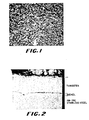
- the coating had a rough surface finish and was free of cracks, as shown in the Figure 1.
- the coating consisted of columnar growth structure, as shown in the Figure 2.
- X-ray diffraction analysis showed the presence of only tungsten in the coating. It had a hardness of 455 Vickers, as shown in Table 3.
- the coating showed very poor erosion performance; time required to penetrate the coating was only 3 seconds, resulting in a erosion rate of 6 seconds/mil. This, therefore, indicated that CVD tungsten could not be used to provide erosion protection.
- the coating thickness on stainless steel specimens was ⁇ 22 ⁇ m.
- the coating consisted of a mixture of W and W3C phases, as determined by x-ray diffraction. It was free of columnar grains.
- the coating had a smooth surface finish. However, the surface of the coating was heavily cracked, as shown in the Figure 5.
- the coating had a hardness of 1788 Vickers, as shown in Table 3.
- the coating showed poor erosion resistance; the breakthrough time and erosion rate were 36 seconds and 42 seconds/mil, respectively.
- the weight loss during erosion test was 0.00036g in 30 seconds. Extensive chipping of the coating was observed during the erosion test. Poor erosion resistance of the coating was probably due to presence of a network of cracks in the coating.
- a two step coating process was used.
- Several AM-350, Ti/6Al/4V and IN-718 specimens were heated to a temperature of about 460°C in the presence of flowing argon and at the reaction temperature a gaseous mixture of 300 cc/min WF6, and 3,000 cc/min of hydrogen was passed into the furnace over the specimens for 5 minutes to coat them with tungsten.
- a gaseous mixture of 300 cc/min WF6, 3,000 cc/min hydrogen and 40 cc/min of DME was passed into the furnace for 55 minutes to provide tungsten/tungsten carbide coating.
- a total pressure was maintained at 40 Torr during tungsten as well as tungsten/tungsten carbide coating steps (see Table 2).
- the stainless steel and Ti/6Al/4V specimens were coated with 2-3 ⁇ m thick tungsten followed by 27-28 ⁇ m thick tungsten/tungsten carbide coating as shown in Table 2.
- the tungsten/tungsten carbide top coat consisted of a mixture of W and W3C phases as shown in Table 3.
- the hardness values of the coating on AM-350 and Ti/6Al/4V are summarized in Table 3.
- the coating on AM-350 and Ti/6Al/4V showed the presence of a network of cracks. Erosion resistance of the coating was extremely poor, as shown in Table 3. Additionally, extensive chipping of the coating was observed during the erosion test. Poor erosion resistance of the coating was probably due to extensive cracking of the coating.
- Example 4A The CVD run described in Example 4A was repeated to provide tungsten followed by tungsten/tungsten carbide coatings.
- the reaction conditions used in tungsten and tungsten/tungsten carbide coating steps are summarized in Table 2.
- the stainless steel specimens were coated with 3 ⁇ m tungsten followed by 25 ⁇ m of tungsten/tungsten carbide.
- the top coat consisted of a mixture of W and W3C phases.
- the coating showed the presence of a network of cracks. Erosion resistance of the coating improved slightly, but it was still extremely poor as shown in Table 3. Additionally, extensive chipping of the coating was observed during the erosion test. Poor erosion resistance was due to the presence of a network of cracks in the coating.
- Example 4A The CVD run described in Example 4A was repeated to provide tungsten followed by slightly thinner tungsten/tungsten carbide coatings.
- the reaction conditions used in tungsten and tungsten/tungsten carbide coating steps are summarized in Table 2.
- the thicknesses of the tungsten and the tungsten/tungsten carbide layers obtained on AM-350 and Ti/6Al/4V are summarized in Table 2.
- the top coat of the coating consisted of a mixture of W and W3C phases.
- the coating once again, showed the presence of a network of cracks.
- the crack density was considerably lower than that observed in Examples 3, 4A and 4B. This suggested that the tungsten interlayer was helpful in reducing the crack density.
- the erosion resistance of the coating was considerably better then that of the coatings obtained in Examples 3, 4A and 4B (see Table 3). The extent of chipping observed during the erosion test also reduced considerably.
- Example 4A The CVD run described in Example 4A was once again repeated to provide tungsten followed by tungsten/tungsten carbide coating.
- the reaction conditions used for depositing tungsten and tungsten/tungsten carbide coatings were selected in such a way to provide a ratio of the thickness of the tungsten to the tungsten/tungsten carbide layers of ⁇ 0.5 (see Table 2).
- the coating showed the presence of cracks, but the crack density was greatly reduced.
- the coating surprisingly, showed superior erosion resistance compared to Examples 3 and 4A to 4C.
- the composite coating obtained in this example showed significantly lower weight loss in the erosion resistance test than Example 3.
- the chipping of the coating observed during the erosion test was reduced dramatically as well. This example, therefore, clearly demonstrated the importance of the tungsten interlayer in reducing cracks and improving erosion resistance of the composite coating.
- reaction conditions for coating tungsten followed by tungsten/tungsten carbide were selected in such a way to provide a ratio of the thickness of the tungsten to the tungsten/tungsten carbide layers of ⁇ 0.68 (see Table 2).
- the composite coating showed the presence of only a few fine cracks (see Figure 6). Etched cross section of the coating clearly showed columnar tungsten interlayer followed by non-columnar W + W3C coating. The composite coating demonstrated superior erosion performance as shown in Table 3.
- reaction conditions for coating tungsten followed by tungsten/tungsten carbide were selected in such a way to slightly increase the thickness ratio (see Table 2).
- Example 4F The CVD run described in Example 4F was repeated using reaction conditions summarized in Table 2 to provide slightly higher tungsten to tungsten/tungsten carbide coating thickness ratio.
- the coating showed presence of a few fine cracks.
- Etched cross section of the coating clearly showed the presence of columnar tungsten interlayer and non-columnar tungsten/tungsten carbide top coat.
- the erosion resistance of the coating was very similar to that observed in Example 4F.
- Example 4G The CVD run described in Example 4G was repeated using reaction conditions summarized in Table 2 to provide even higher tungsten to tungsten/tungsten carbide coating thickness ratio.
- the coating on AM-350, Ti/6Al/4V and IN-718 showed presence of a few cracks.
- the erosion resistance of the coating was very similar to that noted in Examples 4F and 4G.
- the weight loss during the erosion test was considerably lower than that observed earlier.
- Example 4H The CVD run described in Example 4H was repeated to provide even higher tungsten to tungsten/tungsten carbide coating thickness ratio. The higher ratio was obtained by reducing the thickness of the tungsten/tungsten carbide layer.
- the coating showed the presence of a few very fine cracks.
- the erosion resistance of the composite coating was similar to that noted in Example 4H (see Table 3). This example, once again, showed the importance of the tungsten interlayer in reducing cracks and improving erosion resistance of the composite coating. It also showed that the breakthrough time was dependent on the thickness of the tungsten/tungsten carbide layer; whereas, the erosion rate was independent of it.
- Example 4I The CVD run described in Example 4I was repeated to provide even higher tungsten to tungsten/tungsten carbide coating thickness ratio. The higher ratio was obtained by increasing the thickness of the tungsten interlayer.
- the coating once again, showed presence of a few very fine cracks.
- the erosion resistance of the composite coating was slightly higher than that noted earlier (see Table 3). This example also showed the importance of the tungsten interlayer.
- Example 4J The CVD run described in Example 4J was repeated to provide even higher tungsten to tungsten/tungsten carbide coating thickness ratio.
- the coating unexpectedly, was found to be absolutely crack free, as shown in the Figure 7.
- the erosion resistance of the coating was comparable to the data noted earlier.
- Weight loss during erosion test was also comparable to the data noted earlier.
- the W+W3C coating without a W interlayer provided very little erosion protection to the base metal.
- erosion occurs preferentially at cracks which causes chipping and flaking of large pieces of the coating.
- the cracks are believed to occur during the deposition and/or cool-down due to the build up in stresses within the coating.
- the cracks in the coating can be minimized or even eliminated by providing a tungsten interlayer. It is believed that the function of the tungsten interlayer is to accommodate stresses that build up in the coating during the deposition and/or cool-down. The ability to accommodate stress may be in part due to the columnar structure of the tungsten layer, since the compliance of this layer is probably very anisotropic.
- the amount of coating stress which can be accommodated by the tungsten interlayer will depend on its thickness. However, the physical dimensions over which a significant amount of stress accommodation will occur will be limited so that the stresses which are present in the outer layer of a thick tungsten/tungsten carbide coating will be virtually unaffected by the presence of the interlayer. Consequently, both the thickness of the tungsten/tungsten carbide layer and the ratio of the W to the W+W3C thickness are important in obtaining a crack-free composite coating.
- tungsten interlayer in which the thickness of the tungsten interlayer is at least 3 ⁇ m and the ratio of W to W+W3C thickness is at least above 0.3, is necessary to increase the erosion resistance of the composite coating.
- the tungsten interlayer also effects the performance of the tungsten/tungsten coating in a scratch test.
- a diamond stylus is dragged across the surface of the sample at a constantly increasing load.
- the load at which coating loss begins to occur and the extent of coating loss can generally be correlated to the performance of a coating in the erosive and abrasive wear applications.
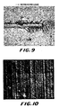
- the tungsten/tungsten carbide coating with no tungsten interlayer as described in Example 3 showed extensive coating loss in the 30-40 Newton load range in the scratch test, as shown in the Figure 8.
- Example 4E When a tungsten interlayer is present as described in Example 4E, the loss of the coating in the same load range is significantly reduced, as demonstrated in the Figure 9; consequently, the presence of a tungsten interlayer is important for erosive and abrasive wear applications.
- a crack-free coating may be highly desirable under certain wear conditions. This conclusion would be especially true in situations where the substrate needs to be completely protected, such as in corrosive-wear environments. A crack-free coating will also be important when a smooth wear surface is required. This crack-free coating was unexpectedly obtained by significantly increasing the ratio of the thickness of the W to the W+W3C layer.
- Example 4K was produced by depositing a thin layer of W+W3C, in theory, a crack-free coating could also be produced by depositing a very thick tungsten interlayer.
- AM-350 specimens were coated in a run.
- the specimens were heated to a temperature of about 460°C in the presence of flowing argon gas and at the reaction temperature a gaseous mixture of 300 cc/min WF6, 3,000 cc/min of hydrogen and 55 cc/min of DME was passed into the furnace over the specimens.
- the total pressure was maintained at 40 Torr, as shown in Table 4.
- the deposition was conducted for 20 minutes.
- the coating thickness was ⁇ 7 ⁇ m (see Table 4). It consisted of a mixture of W, W2C and W3C phases, which was considerably different than observed in Example 3. It was free of columnar grains.
- the micro-structure of the coating consisted of a layered structure. The coating had a smooth surface finish. However, the surface of the coating was cracked, as shown in the Figure 10. The crack density was surprisingly lower than that observed in Example 3.
- the coating had a hardness of 2248 Vickers (Table 5). The coating showed poor erosion resistance; the breakthrough time and erosion rate were 21 seconds and 76 seconds/mil. The erosion resistance, however, was much higher than Example 3.
- the weight loss during erosion test was 0.00042g in 30 seconds, which was very similar to that noted in Example 3. Extensive chiping of the coating was observed during the erosion test. Poor erosion resistance of the coating was probably due to the presence ] of a network of cracks in the coating.
- Example 5A The CVD run described in Example 5A was repeated with Ti/6Al/4V specimens using reaction conditions described in Table 4.
- the specimens were coated with a bright, smooth, adherent, coherent and uniform ⁇ 9.5 ⁇ m thick coating. It consisted of a mixture of W, W2C and W3C phases. It was free of columnar grains. It had a smooth surface finish. It consisted of a network of cracks on the surface. It showed poor erosion resistance (see Table 5), but the erosion resistance was surprisingly better than the coating on AM-350. Once again, extensive chipping was observed during the erosion test. The poor erosion resistance and chipping observed during the erosion testing were due to the presence of cracks in the coating.
- a two step coating process was used.
- Several AM-350 and Ti/6Al/4V specimens were heated to a temperature of 460°C in the presence of flowing argon gas and at the reaction temperature a gaseous mixture of 300 cc/min WF6, 3,000 cc/min of H2, and 4,500 cc/min of argon was passed into the furnace over the specimens for 3 minutes to coat them with tungsten.
- a gaseous mixture of 300 cc/min of WF6, 3,000 cc/min of hydrogen and 55 cc/min of DME was passed into the furnace for 20 minutes to provide tungsten/tungsten carbide coating.
- the total pressure was maintained at 40 Torr during tungsten as well as tungsten/tungsten carbide coating (see Table 4).
- the specimens were coated with tungsten and tungsten/tungsten carbide coating with thicknesses shown in Table 4.
- the tungsten/tungsten carbide top coat consisted of a mixture of W, W2C and W3C phases as shown in Table 5.
- the coating on AM-350 and Ti/6Al/4V showed a few interconnected cracks.
- the erosion resistance of the coating was extremely good, as shown in Table 5. Very little chipping and flaking of the coating was observed during the erosion test. The weight loss during the erosion test was considerably lower than that noted in Examples 5A and 5B.
- This example clearly showed that the erosion resistance of the coating improved significantly by providing a tungsten interlayer.
- This example also showed that a thickness of ⁇ 3 ⁇ m tungsten and a ratio of the thicknesses of tungsten and tungsten/tungsten carbide layers of ⁇ 0.35 are sufficient enough to significantly increase the erosion resistance of the composite coating system. This is an unexpected and significant finding.
- Example 6A The CVD run described in Example 6A was repeated using conditions summarized in Table 4.
- AM-350 and Ti/6Al/4V specimens were coated with 13 ⁇ m and 9.5 ⁇ m thick tungsten/tungsten carbide coating, respectively.
- the ratio of W to tungsten/tungsten carbide coating thickneses was 0.38 and 0.52 on AM-350 and Ti/6Al/4V, respectively.
- the coating both on AM-350 and Ti/6Al/4V had a few fine cracks.
- the coating on AM-350 and Ti/6Al/4V had erosion resistance similar to that noted in Example 6A (see Table 5).
- Example 6B The CVD run described in Example 6B was repeated using conditions summarized in Table 4.
- the specimens wre coated with thicker W and tungsten/tungsten carbide layers.
- the thickness ratio of W and tungsten/tungsten carbide layers was similar to that noted in Example 6B.
- the coating both on AM-350 and Ti/6Al/4V had a few wide cracks.
- the erosion resistance of the coating was similar to that noted in Example 6B.
- Example 6C The CVD run described in Example 6C was repeated using conditions summarized in Table 4 to provide thinner tungsten and tungsten/tungsten carbide layers.
- the thickness ratio obtained was ⁇ 0.63.
- the coating on AM-350 was crack-free , whereas it was cracked on Ti/6Al/4V,.
- the erosion resistance of the coating was similar to that noted in Example 6C.
- This example showed that a crack-free coating on AM-350 could be obtained by providing 6 ⁇ m thick W and 9.5 ⁇ m thick tungsten/tungsten carbide layer. This example also showed that the erosion resistance of the composite coating was unaffected provided the thickness of the tungsten layer was greater than 3 ⁇ m.
- Example 6D The CVD run described in Example 6D was repeated using conditions summarized in Table 4. The thicknesses of the two layers and thickness ratio are shown in Table 4. The coating both on AM-350 and Ti/6Al/4V had cracks. The erosion resistance of the coating was similar to that noted in the Examples 6A to 6D.
- the coatings on all the specimens were cracked.
- the erosion resistance of the coatings was very similar to that noted in Examples 6A to 6E. This example, therefore, showed that the erosion resistance of the coating was independent of the thicknesses of tungsten and tungsten/tungsten carbide layers as long as the thickness of the tungsten layer was greater than 3 ⁇ m.
- Example 6H a photomicrogaph of crack-free coating obtained in Example 6H is shown in the Figure 11.
- These examples exhibited columnar structure of W layer and non-columnar structure of tungsten/tungsten carbide layer.
- the weight loss during the erosion test of coating in Example 6I was very similar to that noted in Example 6A, but it was considerably lower than noted in Examples 5A and 5B.
- the erosion resistance of the W+W2C+W3C coating was very poor in the absence of a W interlayer, due to extensive cracking within the coating.
- cracks within the hard coating can be minimized or even eliminated by the presence of a tungsten interlayer.
- the tungsten interlayer not only helps to reduce cracks, it also improves the erosion resistance.
- a thickness ratio of 0.35 is sufficient for obtaining the optimum erosion resistance. It is an unexpected result that the thickness ratio required to improve the erosion resistance of the W+W2C+W3C coating to its maximum value is significantly lower than that for W+W3C. It is also unexpected that the maximum erosion resistance for W+W2C+W3C is about 30% greater than for W+W3C; consequently W+W2C+W3C is a superior coating for the erosion resistance applications.
- both the ratio of the thicknesses of the W interlayer to the tungsten/tungsten carbide layer and the thickness of the tungsten/tungsten carbide layer are the key parameters for obtaining a crack-free coating.
- the maximum thickness of tungsten/tungsten carbide layer for producing a crack-free coating is ⁇ 11 ⁇ m.
- the critical thickness ratio for a crack-free coating is 0.6 and 0.8 for AM-350 and Ti/6Al/4V, respectively.
- the thickness ratio required for a crack-free W+W2C+W3C coating is quite different than the value for W+W3C. Since a crack-free coating is preferable for some applications, as discussed previously, it is important to know the parameters necessary to obtain such a coating.
- a two step coating process was used.
- Several AM-350 and Ti/6Al/4V specimens were heated to a temperature of 460°C in the presence of flowing argon gas and at the reaction temperature a gaseous mixture of 300 cc/min WF6, 3,000 cc/min of H2, and 4,500 cc/min of argon was passed into the furnace over the specimens for 15 minutes to coat them with tungsten.
- a gaseous mixture of 300 cc/min of WF6, 3,000 cc/min of H2 and 85 cc/min of DME was passed into the furnace for 70 min to provide tungsten/tungsten carbide coating.
- the total pressure was maintained at 40 Torr during tungsten as well as tungsten/tungsten carbide coating steps (see Table 6).
- the specimens were coated with tungsten and tungsgen/tungsten carbide of thicknesses ⁇ 8 ⁇ m and ⁇ 23 ⁇ m, respectively. These thickness values gave a thickness ratio of ⁇ 0.35.
- the tungsten/tungsten carbide top coat consisted of a mixture of W and W2C phases, as shown in Table 7.
- the coating on the specimens showed a few fine cracks.
- the erosion resistance of the coating was extremely good, as shown in Table 7. No chipping or flaking was observed during the erosion test, which was surprising when compared to W+W3C and W+W2C+W3C coatings.
- the weight loss was slightly higher in this example than that observed with W+W2C+W3C coating with W interlayer. This could be related to the fact the cracks in W + W2C coatings were slightly wider than those noted in W + W2C + W3C coating.
- Examples 7A and 7B clearly showed that a tungsten to tungsten/tungsten carbide thickness ratio of ⁇ 0.35 is sufficient enough to give a maximum erosion resistance.
- Example 7B The CVD run described in Example 7B was repeated to provide slightly higher thickness ratio.
- the thickness of W + W2C layer varied from 10 ⁇ m to 11 ⁇ m on various substrates, and the ratio varied from 0.44 to 0.50.
- the coating on AM-350 and IN-718 was crack-free; whereas, a few fine cracks were observed on Ti/6Al/4V. This indicated that crack-free coating on AM-350 and IN-718 can be obtained by providing ⁇ 5 ⁇ m thick W and ⁇ 10 to 11 ⁇ m thick W + W2C layers. These thickness values, however, were not good enough to give crack-free coating on Ti/6Al/4V.
- the erosion resistance of the coating was very good as shown in Table 7.
- Example 7C The CVD run described in Example 7C was repeated to provide slightly thicker W + W2C layer while maintaining thickness ratio. Surprisingly, the coating on AM-350 and Ti/6Al/4V cracked. This information suggested that the thickness of W + W2C layer was important to prevent cracks in the coating. The erosion resistance of the coating was good, as shown in Table 7.
- Example 70 The CVD run described in Example 70 was repeated to provide slightly thinner W + W2C layer and slightly higher thickness ratio.
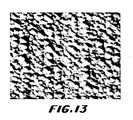
- the coating on AM-350, Ti/6Al/4V and IN-718 was absolutely crack-free (see Figure 13), certifying the importance of the thickness of W + W2C.
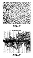
- the unetched and etched cross-sectional views of the composite coatings are shown in the Figures 3 and 4.
- the etched cross-section presented in the Figure 4 showed columnar growth of the tungsten interlayer and the non-columnar growth of the tungsten/tungsten carbide layer.
- the etched cross-section of the coating also demonstrated the absence of any cracks in the coating.
- the erosion resistance of the coating was good, as shown in Table 7.
- Example 7E The CVD run described in Example 7E was repeated in these examples to verify the concept of crack-free coating.
- the coatings obtained in these runs were absolutely crack-free. They also had good erosion resistance, as shown in Table 7.
- the thickness of W and W + W2C layers was slightly increased on AM-350 stainless steel to determine its effect on cracks.
- the thickness ratio obtained was ⁇ 0.6.
- This information further confirmed the statement made earlier that the thickness of W + W2C layer played an important role in obtaining crack-free coating. Erosion resistance of the coating was good, as shown in Table 7.
- the erosion resistance of W+W2C coating is either equivalent to or superior to the erosion resistance of W+W2C+W3C.
- the erosion resistance of W+W2C is independent of the thickness of the tungsten interlayer when the ratio of the W to the W+W2C thickness is at least 0.35.
- the wear performance of the uncoated stainless steel 1" diameter SS-422 disc was determined using a ball-on-disc test in the presence and absence of a lubricant.
- the non-lubricated wear test was conducted in dry air (1% relative humidity) and saturated air (99% relative humidity).
- the lubricated wear test was conducted in the presence of a cutting fluid consisting of an emulsion of 20% mineral oil in water.
- the ball used in the test was made of 52-100 chrome steel.
- the ball-on-disc wear test was performed using a load of 5 Newton, ambient temperature, stationary ball on rotating disc at a speed of 10 cm/sec., and for approximately 0.3 kilometer.
- the wear performance was determined by measuring the combined volumetric material loss of the ball and disc. Th wear rate was very high in the dry air (1% relative humidity), as shown in the Table 8.
- the wear rate in the saturated air (99% relative humidity) and cutting fluid, on the other hand, was considerably lower, with the rate being lowest in the presence of the lubricant.
- a two-step coating process was used.
- Several SS-422 discs were heated to a temperature of bout 460°C in the presence of flowing argon and at the reaction temperature a gaseous mixture of 300 cc/min WF6, 3,000 cc/min hydrogen, and 4,500 cc/min of argon was passed into the furnace over the specimens for 15 minutes to coat them with tungsten.
- a gaseous mixture of 300 cc/min WF6, 3,000 cc/min hydrogen, 300 cc/min argon and 40 cc/min of DME was passed into the furnace for 30 minutes to provide tungsten/tungsten carbide coating.
- a total pressure was maintained at 40 Torr during the tungsten as well as tungsten/tungsten carbide coating steps.
- the SS-422 discs were coated with 10.4 ⁇ m thick tungsten followed by 12.4 ⁇ m thick tungsten/tungsten carbide.
- the tungsten/tungsten carbide top coat consisted of a mixture of W and W3C phases. The hardness of the top coat was approximately 2450 Vickers. The coating was smooth and had a few very fine interconnected cracks.
- the wear performance of the coated SS-422 disc was determined using ball-on-disc test described in the Example 8 in the presence of 1% and 99% relative humidity and cutting fluid as a lubricant.
- the wear rate data summarized in the Table 8 showed dramatically lower wear rate in the presence of dry air (1% relative humidity) compared to the uncoated disc.
- the wear rate in the presence of 99% relative humidity and cutting fluid was also lower than the uncoated disc.
- a two-step coating process was used again.
- Several SS-422 discs were heated to a temperature of about 460°C in the presence of flowing argon and at the reaction temperature a gaseous mixture of 300 cc/min WF6, 3,000 cc/min hydrogen, and 4,500 cc/min of argon was passed into the furnace over the specimens for 15 minutes to coat them with tungsten.
- a gaseous mixture of 300 cc/min WF6, 3,000 cc/min hydrogen, 300 cc/min argon and 60 cc/min of DME was passed into the furnace for 40 minutes to provide tungsten/tungsten carbide coating.
- a total pressure was maintained at 40 Torr during the tungsten as well as tungsten/tungsten carbide coating steps.
- the SS-422 discs were coated with 9.7 ⁇ m thick tungsten followed by 14.0 ⁇ m thick tungsten/tungsten carbide.
- the tungsten/tungsten carbide top coat consisted of a mixture of W, W2C and W3C phases. It had a hardness of approximately 2250 Vickers. The coating was smooth and had a few extremely fine and long cracks.
- Table 8 Example No. Composition of the Tungsten/Tungsten Carbide Top Coat Total Wear Rate. 10 ⁇ 15m2/N 1% Humidity 99% Humidity Cutting Fluid Example 8 -- 327 8.1 2.9
- the wear performance of the coated SS-422 disc was determined using ball-on-disc test described in the Example 8 in the presence of 1% and 99% relative humidity and cutting fluid as a lubricant.
- the wear rate data summarized in the Table 8 showed lower wear rate in the presence of 1% and 99% relative humidity and cutting fluid compared to the uncoated disc and disc coated with tungsten followed by W+W3C coating.
- This example shows that a composite coating is very effective in improving wear performance of the SS-422 disc. It also shows that the wear performance of the composite coating can be improved by adjusting the composition of the tungsten/tungsten carbide top coat.
- a two-step coating process was used again.
- Several SS-422 discs were heated to a temperature of about 460°C in the presence of flowing argon and at the reaction temperature a gaseous mixture of 300 cc/min WF6, 3,000 cc/min hydrogen, and 4,500 cc/min of argon was passed into the furnace over the specimens for 15 minutes to coat them with tungsten.
- a gaseous mixture of 300 cc/min WF6, 3,000 cc/min hydrogen, 300 cc/min argon and 80 cc/min of DME was passed into the furnace for 40 minutes to provide tungsten/tungsten carbide coating.
- a total pressure was maintained at 40 Torr during the tungsten as well as tungsten/tungsten carbide coating steps.
- the SS-422 discs were coated with 10 ⁇ m thick tungsten followed by 13.0 ⁇ m thick tungsten/tungsten carbide.
- the tungsten/tungsten carbide top coat consisted of a mixture of W and W2C phases. It had a hardness of approximately 2750 Vickers. The coating was smooth and crack-free.
- the wear performance of the coated SS-422 disc was determined using ball-on-disc test described in Example 8 in the presence of 1% and 99% relative humidity and cutting fluid as a lubricant.
- the wear rate data summarized in Table 8 showed the wear rate was similar to that noted with the other composite coatings (i.e., W+W3C and W+W2C+W3C coatings) in the presence of dry air (1% relative humidity) and cutting fluid.
- the wear rate was lower compared to other composite coatings in the presence of 99% relative humidity.
- This example shows that a composite coating is very effective in improving wear performance of the SS-422 disc.
- the wear data presented in Examples 8 to 11 clearly demonstrate that a composite tungsten followed by tungsten/tungsten carbide coating can be used to significantly reduce the abrasive wear rate and concomitantly increase the life of the stainless steel material in the dry, humid and lubricated environments.
- the data presented in Examples 1 to 4 show that the composite coating is very effective in reducing the erosive wear rate of the ferrous and non-ferrous alloys. Additionally, Examples 1 to 4 show that an interlayer of tungsten is required to improve the performance of the tungsten/tungsten carbide coating. This is an unexpected finding.
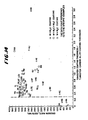
- the relationship between the ratio of the thickness of the tungsten interlayer to the thickness of the tungsten-carbon alloy (tungsten/tungsten carbide coating) is elaborated further in the Figure 14. It shows that for W+W3C top coat the erosion resistance measured as secs/mil increases with increasing the thickness ratio. A thickness ratio greater than 0.3 is required to significantly increase the erosion resistance of the W+W3C coating system. Furthermore, a thickness ratio of about 0.6 is required to obtain optimum erosion resistance of the W+W3C coating system. Figure 14 also shows that a thickness ratio of greater than 0.3 is required for significantly increasing the erosion resistance of the W+W2C+W3C coating system.
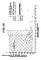
- the relationship between the thickness of the tungsten-carbon alloy and the ratio of the thickness of the tungsten interlayer to the thickness of the tungsten-carbon alloy (tungsten/tungsten carbide coating) is presented in Figure 15. It shows a very narrow region for obtaining a crack-free W+W3C coating system. A thin W+W3C layer is required to achieve a crack-free coating. Compared to the W+W3C coating system, the W+W2C+W3C and W+W2C coating systems provide a wider crack-free coating region.
- a thicker crack-free tungsten/tungsten carbide coating can be obtained for W+W2C top coat than is possible for W+W2C+W3C or for W+W3C.
- the thickness of the tungsten interlayer which is required to achieve a crack-free coating is significantly lower for W+W2C than for W+W2C+W3C or W+W3C.
- One particularly important use of the composite coating system according to the present invention is to provide highly erosive and abrasive wear resistant coatings on ferrous, non-ferrous and titanium alloy compressor blades for gas turbines and jet engines.
Abstract
Description
- The invention relates to highly erosive and abrasive wear resistant composite coating. More particularly, the invention relates to an improved highly erosive and abrasive wear resistant coating comprising a composite coating system of an intermediate layer of substantially pure tungsten and an outer two phase layer of a mixture of tungsten and tungsten carbide.
- High hardness materials are widely used as coatings on various type of mechanical components and cutting tools. Such coatings impart erosion and abrasion wear resistance and thus increase the erosive and abrasive wear life of objects that have been coated. The high hardness materials can also be used to produce free standing objects which are erosive and abrasive wear resistant.
- Chemical vapor deposition processes can be used to produce highly erosive and abrasive wear resistant hard coatings and free standing objects. In a typical chemical vapor deposition (CVD) process, the substrate to be coated is heated in a suitable chamber and then a gaseous reactant mixture is introduced into the chamber. The gaseous reactant mixture reacts at the surface at the substrate to form a coherent and adherent layer of the desired coating. By varying the gaseous reactant mixture and the CVD process parameters, various types of deposited coatings can be produced.
- In co-pending U.S. Patent Application Serial No. 92,809, filed 3 September 1987, extremely hard, fine grained, non-columnar, substantially lamellar tungsten/carbon alloys are described which are produced by chemical vapor deposition. The described alloys consist primarily of a mixture of a substantially pure tungsten phase and at least one carbide phase wherein the carbide phase consists of W₂C or W₃C or a mixture of W₂C and W₃C. The disclosed tungsten/carbon alloys are free of columnar grains and consist essentially of extremely fine, equiaxial crystals.
- It has been found that the tungsten/carbon alloys such as those described in the aforementioned U.S. Patent Application, when deposited upon certain types of substrates, exhibit a very fine micro-crack system throughout the deposit. On many types of substrates and under many types of erosive and abrasive wear conditions, preferential attack occurs at the cracks, resulting in poor erosion and abrasion wear resistance for such coatings.
- The use of an intermediate layer of substantially pure tungsten followed by a tungsten carbide coating is described in the prior art. For example, U.S. Patent No. 3,389,977 discloses a method of depositing substantially pure tungsten carbide in the form W₂C wherein the adherence of W₂C to a steel substrate is improved by first cleaning the surface and then depositing a thin film of tungsten. The thin film of tungsten is deposited at or above 600°C, making the use of the deposition process unsuitable for providing erosive and abrasive wear resistance coating on various carbon steels, stainless steels, nickel and titanium alloys without severely degrading their mechanical properties. Additionally, pure W₂C deposited according to this patent consists of columnar grains as opposed to non-columnar grains described in the present patent application. Other instances of the use of very thin tungsten intermediate layers, often as a diffusion layer, are reported in other prior art in order to improve adhesion of tungsten carbide on a substrate. However, there is no report in the prior art of the effect of a tungsten interlayer on coating properties of the final coating system nor has the effect of such a tungsten intermediate layer on the reduction or elimination of cracks in the outer coating been reported.
- Very generally, the highly erosive and abrasive wear resistant composite coating system of the invention comprises an intermediate layer of tungsten and an outer layer of tungsten/carbon alloy coating. The intermediate layer of tungsten is of sufficient thickness to confer substantial erosive and abrasive wear resistance characteristics to the composite coating system. The outer tungsten/carbon alloy layer is comprised of a mixture of tungsten and tungsten carbide, with the tungsten carbide phase comprising of W₂C, W₃C or a mixture of both. The ratio of the thickness of the intermediate or inner layer to the thickness of the outer layer is at least above 0.3 in the cases of W+W₃C, W+W₂C+W₃C and W+W₂C coatings. Preferably the ratio of the thickness of the inner layer to the thickness of the outer layer to get optimum erosion and abrasion wear performance is at least 0.35 in the case of mixtures of tungsten and W₂C in the outer layer, 0.60 in the case of mixtures of tungsten and W₃C in the outer layer and, 0.35 in the case of mixtures of tungsten and W₂C and W₃C in the outer layer.
- The tungsten/carbon alloys or coatings consisting of a mixture of tungsten and tungsten carbide, with the tungsten carbide phase comprising W₂C, W₃C or mixtures of both are defined herein as tungsten/tungsten carbide to simplify the description.
-
- FIGURE 1 is the photomicrograph at 1,000 magnification of the tungsten coating on AM-350 stainless steel showing a rough surface finish but the absence of cracks.
- FIGURE 2 is the cross-sectional view at 3,000 magnification of the tungsten coating on AM-350 stainless steel showing columnar growth structure.
- FIGURE 3 is the schematic of the unetched cross-sectional view at 2,000 magnification of the composite coating system on AM-350 stainless steel substrate constructed in accordance with the invention.
- FIGURE 4 is the schematic of the cross-sectional view at 2,000 magnification of the composite coating system on AM-350 stainless steel etched with the murakami solution constructed in accordance with the invention.
- FIGURE 5 is the photomicrograph of the W+W₃C coating without the tungsten interlayer at 1,000 magnification on AM-350 stainless steel showing a network of interconnected cracks.
- FIGURE 6 is the photomicrograph of the W+W₃C coating with the tungsten interlayer at 1,000 magnification on AM-350 stainless steel showing a few interconnected cracks.
- FIGURE 7 is the photomicrograph of the W+W₃C coating with the tungsten interlayer at 1,000 magnification on AM-350 stainless steel showing the absence of cracks.
- FIGURE 8 is the photomicrograph of the surface of W+W₃C coating without the tungsten interlayer on AM-350 stainless steel at 100 magnification, scratched with a diamond stylus and showing significant loss of the coating in the 30-40 Newton load range.
- FIGURE 9 is the photomicrograph of the surface of W+W₃C coating with the tungsten interlayer on AM-350 stainless steel at 100 magnification, scratched with a diamond stylus and showing significantly reduced loss of the coating in the 30-40 Newton load range.
- FIGURE 10 is the photomicrograph of the W+W₂C+W₃C coating without the tungsten interlayer on AM-350 stainless steel at 1,000 magnification showing a network of cracks.
- FIGURE 11 is the photomicrograph of the W+W₂C+W₃C coating with the tungsten interlayer on AM-350 stainless steel at 1,000 magnification showing the absence of cracks.
- FIGURE 12 is the photomicrograph of the W+W₂C coating with the tungsten interlayer on AM-350 stainless steel at 1,000 magnification showing the presence of a fine crack.
- FIGURE 13 is the photomicrograph of the W+W₂C coating with the tungsten interlayer on AM-350 stainless steel at 1,000 magnification showing the absence of cracks.
- FIGURE 14 is the graph illustrating the relationship between the erosion rate and the ratio of the tungsten to the tungsten/carbon alloy coating thicknesses on AM-350 stainless steel, and
- FIGURE 15 is the graph illustrating the relationship between the tungsten/carbon alloy coating thickness and the ratio of the thicknesses of the tungsten layer to the tungsten/carbon alloy layer on AM-350 stainless steel.
- In a preferred form of the invention, the intermediate layer of tungsten is produced by chemical vapor deposition under sub-atmospheric to slightly atmospheric pressure, i.e., within the range of about 1 Torr. to about 1,000 Torr., at a temperature of about 300° to about 650°C., using a mixture of tungsten halide such as WF₆, hydrogen, and an inert gas such as argon. The intermediate layer is of a sufficient thickness to confer substantial erosive and abrasive wear resistance characteristics on the composite system. The specific thickness necessary to do this for various composite coating systems will become readily apparent to those skilled in the art from the teaching of this specification, particularly in connection with the examples set forth below. The intermediate layer of tungsten should be at least about two microns thick and, for most systems, will be greater than about three microns.
- Following deposition of the intermediate layer of substantially pure tungsten, an outer layer of tungsten/tungsten carbide is deposited under sub-atmospheric to slightly atmospheric pressure, i.e., within the range of about 1 Torr. to about 1,000 Torr., at temperatures in the range of about 300° to about 650°C. This outer layer may be either a two phase layer comprising tungsten and W₂C or tungsten and W₃C. Alternatively, this outer layer may be a three phase layer comprising tungsten, W₂C and W₃C. The relative proportions of the tungsten, W₂C, and W₃C may be selected in accordance with the particular properties desired in the final composite coating system. In order to achieve such proportions, the tungsten/tungsten carbide deposit is applied utilizing a flow of tungsten halide such as WF₆, argon, hydrogen and an oxygen containing hydrocarbon such as dimethylether (DME). By controlling the temperature, W/C atomic ratio in the feed gas and the ratio of hydrogen of WF₆ during the deposition reaction, the particular desired chemical composition of the tungsten/tungsten carbide layer may be obtained. Details of the foregoing described process may be found in applicant's co-pending U.S. Patent Application Serial No. 92,809.
- In accordance with the present invention, it has been found that the ratio of the thickness of the inner tungsten layer to the thickness of the outer multi-phase tungsten/tungsten carbide layer has a profound affect on the erosive and abrasive wear resistance properties of the resulting composite coating system. Although the reasons for this improvement in the erosive and abrasive wear resistance are yet not fully understood, it is believed that the use of the tungsten intermediate layer together with the specified ratios set forth below refine the micro-crack structure in the outer deposit so that, even though preferential attack along the crack system occurs, the rate of attack is greatly attenuated. Moreover, as set out below, under certain conditions a crack free outer layer may be achieved.
- More specifically, the ratio of the thickness of the inner tungsten layer to the thickness of the outer tungsten/tungsten carbide layer, in accordance with the composite coating system of the invention, is at least about 0.30 with the W+W₃C, W+W₂C+W₃C and W+W₂C coatings. More specifically, to obtain optimum erosion and abrasion wear performance the thickness ratio is at least: 0.35 in the case of mixtures of tungsten and W₂C in the outer layer, 0.60 in the case of mixtures of tungsten and W₃C and W₃C in the outer layer. Using these minimum ratios, superior erosive and abrasive wear resistance can be achieved. Moreover, by using the ratios set forth above, under certain conditions, completely crack free outer layers may be achieved.
- The inner tungsten layer is substantially columnar in its grain structure with the longer dimension of the grains extending generally perpendicular to the substrate surface. On the other hand, the grain structure of the tungsten/tungsten carbide outer layer is very fine-grained, equiaxed, non-columnar, and substantially lamellar typically of the order of one micron or less in size. Such structures may be readily achieved using the method described in the aforementioned co-pending United States patent application.
- The present composite coating system of the invention can be deposited on a number of ferrous metals and alloys such as cast irons, carbon steels, stainless steels and high speed steels, non-ferrous metals and alloys such as copper, nickel, platinum, rhodium, titanium, aluminum, silver, gold, niobium, molybdenum, cobalt, tungsten, rhenium, copper alloys and nickel alloys such as inconel and monel, titanium alloys such as Ti/Al/V, Ti/Al/Sn, Ti/Al/Mo/V, Ti/Al/Sn/Zr/Mo, Ti/Al/V/Cr, Ti/Mo/V/Fe/Al, Ti/Al/V/Cr/Mo/Z and Ti/Al/V/Sn alloys, non-metals such as graphite, carbides such as cemented carbide, and ceramics such as silicon carbide, silicon nitride, alumina, etc. In depositing the composite coating system on reactive substrate materials, such as cast irons, carbon steels, stainless steels, high speed steels, and nickel and monel alloys, it is preferred to coat the substrate first with a more noble material such as nickel, cobalt, copper, silver, gold, platinum, palladium or iridium, by electrochemical or electroless techniques or by a physical vapor deposition technique such as sputtering. In depositing the composite coating system on reactive titanium or titanium alloys, it is also preferred to coat the substrate first with a more noble material described above by electroless technique or by physical vapor deposition technique such as sputtering. It is also preferred to coat the substrate first with a thin layer of a more noble material described above by electroless technique followed by another thin layer of a more noble material by electrochemical or physical vapor deposition technique. It is also preferred to clean the surface of the titanium or titanium alloy substrate first and heat treat the noble metal deposit after depositing on the substrate. The deposition of noble metal and subsequent heat treatment steps on titanium or titanium alloys are described in detail in co-pending U.S. Patent Application Serial No. (Docket No. 720-P-US03673), filed 31 December l987 (Docket No. 720-P-US03673). It is also preferred that upper limit of the deposition temperature be about 525°C when depositing the present composite coating system on titanium and titanium alloys to minimize the degradation of the mechanical properties. No deposition of the noble material, however, is required for coating non-reactive materials such as copper, nickel, cobalt, silver, gold, platinum, rhodium, niobium, molybdenum, tungsten, rhenium, graphite, carbides and ceramics. Free standing parts of the composite coating of the present invention can be made by depositing it on the substrates such as copper, nickel, cobalt, silver, gold, molybdenum, rhenium, and graphite and then removing these substrates by grinding and chemical or electrochemical etching.
- To further illustrate the present invention, the following data are set forth with respect to a number of coating systems.
- A number of ferrous and non-ferrous metals and alloys were used as substrates in the following coating experiments. Specimens of AM-350 and SS-422 stainless steels Inconel and IN-718, a well known nickel alloy, were electroplated with 2 to 5 µm thick nickel before coating them with tungsten and tungsten/tungsten carbide to protect them from the attack of hot and corrosive HF acid gas produced as a by-product in the CVD process. Specimens made of titanium alloy such as Ti/6Al/4V, on the other hand, were plated with 2 to 5 µm thick nickel using an electroless technique described in detail in co-pending U.S. Patent Application Serial No. , filed 31 December 1987 (Docket No. 720-P-US03673 before coating them with tungsten and tungsten/tungsten carbide.
- The erosion resistance performance of the uncoated and the coated specimens are determined using a miniature sandblast unit; the test parameters are summarized in Table 1. The fine alumina powder, which was used as the erosive material, provide a very harsh erosion environment, as compared to sand erosion; consequently, an accelerated test procedure could be used. Two essentially equivalent techniques were used to evaluate the erosion resistance of the specimens. The first technique involved measuring the time it took for the erosive material to penetrate the tungsten/tungsten carbide coating, which is called the breakthrough time. Penetration of the tungsten/tungsten carbide coating was visibly apparent as a color change at the center of the erosion pit; the fact that this color change corresponded to the initial penetration of the tungsten/tungsten carbide coating was confirmed by microscopic examination of erosion pits in cross section. The second technique involved measuring the weight of a specimen that was lost during an erosion test for a given time; this time was always less than the breakthrough time so that only the weight loss of the coating was measured. The erosion rate was then calculated as the time required to penetrate the coating on a per mil basis or as the average weight loss for a 30 second erosion test, respectively.
- Uncoated specimens of AM-350 stainless steel and Ti/6Al/4V were eroded with alumina for two minutes (120 seconds). The depth of the crater was measured to calculate the erosion rate. The calculated erosion rate was 60 and 50 seconds/mil for AM-350 and Ti/6Al/4V specimens, respectively.
- A number of AM-350, Ti/6Al/4V and IN-718 specimens (0.095 inch x 1 inch x 2 inch) were placed in an inductively heated graphite furnace inside a gas-tight quartz envelope. The specimens were heated to 460°C in the presence of flowing argon gas and at the temperature a gaseous mixture of 300 cc/min of WF₆, 3,000 cc/min of hydrogen, and 4,000 cc/min of argon was passed into the furnace over the specimens. The total pressure within the system was maintained at 40 Torr. The deposition was conducted for 15 minutes; thereafter, the flow of the reactive gases was stopped and the specimens were cooled.
- The specimens were found to be coated with a dull, adherent, coherent, and uniform coating. The coating thickness on stainless steel specimens was ∼12 µm on each side (see Table 2). The coating had a rough surface finish and was free of cracks, as shown in the Figure 1. The coating consisted of columnar growth structure, as shown in the Figure 2. X-ray diffraction analysis showed the presence of only tungsten in the coating. It had a hardness of 455 Vickers, as shown in Table 3. The coating showed very poor erosion performance; time required to penetrate the coating was only 3 seconds, resulting in a erosion rate of 6 seconds/mil. This, therefore, indicated that CVD tungsten could not be used to provide erosion protection.
Table 1 Erosion Test Procedure Nozzle Diameter 0.018 inch Stand off Distance 0.6 inch Erosion Media Fine Alumina Powder (50 µm Average Particle Size) Supply Pressure 32 psig Flow Rate of Erosion Media 1.6 g/min Erosion Test Standard Breakthrough Time and Weight Loss 


- In this example, several specimens of AM-350, Ti/6Al/4V and IN-718 were coated simultaneously in a single run. The specimens were heated to a temperature of about 460°C in the presence of flowing argon and at the reaction temperature a gaseous mixture of 300 cc/min WF₆, 3,000 cc/min of hydrogen and 40 cc/min of DME was passed into the furnace over the specimens. The total pressure was maintained at 40 Torr, as shown in Table 2. The deposition was conducted for 40 minutes.
- All the specimens were coated with a bright, smooth, adherent, coherent and uniform coating. The coating thickness on stainless steel specimens was ∼22 µm. The coating consisted of a mixture of W and W₃C phases, as determined by x-ray diffraction. It was free of columnar grains. The coating had a smooth surface finish. However, the surface of the coating was heavily cracked, as shown in the Figure 5. The coating had a hardness of 1788 Vickers, as shown in Table 3. The coating showed poor erosion resistance; the breakthrough time and erosion rate were 36 seconds and 42 seconds/mil, respectively. The weight loss during erosion test was 0.00036g in 30 seconds. Extensive chipping of the coating was observed during the erosion test. Poor erosion resistance of the coating was probably due to presence of a network of cracks in the coating.
- In this example, a two step coating process was used. Several AM-350, Ti/6Al/4V and IN-718 specimens were heated to a temperature of about 460°C in the presence of flowing argon and at the reaction temperature a gaseous mixture of 300 cc/min WF₆, and 3,000 cc/min of hydrogen was passed into the furnace over the specimens for 5 minutes to coat them with tungsten. After coating specimens with tungsten for 5 minutes, a gaseous mixture of 300 cc/min WF₆, 3,000 cc/min hydrogen and 40 cc/min of DME was passed into the furnace for 55 minutes to provide tungsten/tungsten carbide coating. A total pressure was maintained at 40 Torr during tungsten as well as tungsten/tungsten carbide coating steps (see Table 2).
- The stainless steel and Ti/6Al/4V specimens were coated with 2-3 µm thick tungsten followed by 27-28 µm thick tungsten/tungsten carbide coating as shown in Table 2. The tungsten/tungsten carbide top coat consisted of a mixture of W and W₃C phases as shown in Table 3. The hardness values of the coating on AM-350 and Ti/6Al/4V are summarized in Table 3. The coating on AM-350 and Ti/6Al/4V showed the presence of a network of cracks. Erosion resistance of the coating was extremely poor, as shown in Table 3. Additionally, extensive chipping of the coating was observed during the erosion test. Poor erosion resistance of the coating was probably due to extensive cracking of the coating.
- This example described that providing a very thin interlayer of tungsten did not help in improving erosion resistance of the overall composite coating.
- The CVD run described in Example 4A was repeated to provide tungsten followed by tungsten/tungsten carbide coatings. The reaction conditions used in tungsten and tungsten/tungsten carbide coating steps are summarized in Table 2.
- The stainless steel specimens were coated with 3 µm tungsten followed by 25 µm of tungsten/tungsten carbide. The top coat consisted of a mixture of W and W₃C phases. The coating showed the presence of a network of cracks. Erosion resistance of the coating improved slightly, but it was still extremely poor as shown in Table 3. Additionally, extensive chipping of the coating was observed during the erosion test. Poor erosion resistance was due to the presence of a network of cracks in the coating.
- This example described that increasing the ratio of the thickness of the tungsten to the tungsten/tungsten carbide layer helped in improving the erosion resistance of the composite coating.


- The CVD run described in Example 4A was repeated to provide tungsten followed by slightly thinner tungsten/tungsten carbide coatings. The reaction conditions used in tungsten and tungsten/tungsten carbide coating steps are summarized in Table 2.
- The thicknesses of the tungsten and the tungsten/tungsten carbide layers obtained on AM-350 and Ti/6Al/4V are summarized in Table 2. The top coat of the coating consisted of a mixture of W and W₃C phases. The coating, once again, showed the presence of a network of cracks. However, the crack density was considerably lower than that observed in Examples 3, 4A and 4B. This suggested that the tungsten interlayer was helpful in reducing the crack density. The erosion resistance of the coating was considerably better then that of the coatings obtained in Examples 3, 4A and 4B (see Table 3). The extent of chipping observed during the erosion test also reduced considerably.
- This example showed that increasing the ratio of the thickness of the tungsten layer to that of the tungsten/tungsten carbide layer from ∼0.07 to 0.12 in Examples 4A and 4B to ∼0.2 to 0.3 in this example unexpectedly reduced cracks in the coating and improved its erosion resistance.
- The CVD run described in Example 4A was once again repeated to provide tungsten followed by tungsten/tungsten carbide coating. The reaction conditions used for depositing tungsten and tungsten/tungsten carbide coatings were selected in such a way to provide a ratio of the thickness of the tungsten to the tungsten/tungsten carbide layers of ∼0.5 (see Table 2).
- The coating showed the presence of cracks, but the crack density was greatly reduced. The coating, surprisingly, showed superior erosion resistance compared to Examples 3 and 4A to 4C. Furthermore, the composite coating obtained in this example showed significantly lower weight loss in the erosion resistance test than Example 3. The chipping of the coating observed during the erosion test was reduced dramatically as well. This example, therefore, clearly demonstrated the importance of the tungsten interlayer in reducing cracks and improving erosion resistance of the composite coating.
- In this example, reaction conditions for coating tungsten followed by tungsten/tungsten carbide were selected in such a way to provide a ratio of the thickness of the tungsten to the tungsten/tungsten carbide layers of ∼0.68 (see Table 2).
- The composite coating showed the presence of only a few fine cracks (see Figure 6). Etched cross section of the coating clearly showed columnar tungsten interlayer followed by non-columnar W + W₃C coating. The composite coating demonstrated superior erosion performance as shown in Table 3.
- This example clearly demonstrated the importance of the tungsten interlayer in reducing cracks and improving erosion resistance of the composite coating.
- In this example, reaction conditions for coating tungsten followed by tungsten/tungsten carbide were selected in such a way to slightly increase the thickness ratio (see Table 2).
- Once again, the coating on AM-350 and Ti/6Al/4V showed presence of a few cracks. Erosion resistance of the composite coating summarised in Table 3 was better than Example 4E. This example also demonstrated the importance of the tungsten interlayer in reducing cracks and improving erosion resistance.
- The CVD run described in Example 4F was repeated using reaction conditions summarized in Table 2 to provide slightly higher tungsten to tungsten/tungsten carbide coating thickness ratio.
- Once again, the coating showed presence of a few fine cracks. Etched cross section of the coating clearly showed the presence of columnar tungsten interlayer and non-columnar tungsten/tungsten carbide top coat. The erosion resistance of the coating was very similar to that observed in Example 4F.
- The CVD run described in Example 4G was repeated using reaction conditions summarized in Table 2 to provide even higher tungsten to tungsten/tungsten carbide coating thickness ratio.
- The coating on AM-350, Ti/6Al/4V and IN-718 showed presence of a few cracks. The erosion resistance of the coating was very similar to that noted in Examples 4F and 4G. The weight loss during the erosion test was considerably lower than that observed earlier.
- This example, therefore, showed the importance of the tungsten interlayer in reducing the cracks in the coating and in improving the erosion resistance of the coating. It also showed that increasing the thickness of the tungsten interlayer to ∼16 µm without increasing that of the tungsten/tungsten carbide did not help in further increasing the erosion resistance of the coating.
- The CVD run described in Example 4H was repeated to provide even higher tungsten to tungsten/tungsten carbide coating thickness ratio. The higher ratio was obtained by reducing the thickness of the tungsten/tungsten carbide layer.
- The coating showed the presence of a few very fine cracks. The erosion resistance of the composite coating was similar to that noted in Example 4H (see Table 3). This example, once again, showed the importance of the tungsten interlayer in reducing cracks and improving erosion resistance of the composite coating. It also showed that the breakthrough time was dependent on the thickness of the tungsten/tungsten carbide layer; whereas, the erosion rate was independent of it.
- The CVD run described in Example 4I was repeated to provide even higher tungsten to tungsten/tungsten carbide coating thickness ratio. The higher ratio was obtained by increasing the thickness of the tungsten interlayer.
- The coating, once again, showed presence of a few very fine cracks. The erosion resistance of the composite coating was slightly higher than that noted earlier (see Table 3). This example also showed the importance of the tungsten interlayer.
- The CVD run described in Example 4J was repeated to provide even higher tungsten to tungsten/tungsten carbide coating thickness ratio.
- The coating, unexpectedly, was found to be absolutely crack free, as shown in the Figure 7. The erosion resistance of the coating was comparable to the data noted earlier. Weight loss during erosion test was also comparable to the data noted earlier.
- This example demonstrated that a crack-free coating could be obtained by manipulating the ratio of the thickness of the tungsten and the tungsten/tungsten carbide layers. This is an unexpected and significant finding.
- Because of extensive cracking, the W+W₃C coating without a W interlayer provided very little erosion protection to the base metal. In this case, erosion occurs preferentially at cracks which causes chipping and flaking of large pieces of the coating. The cracks are believed to occur during the deposition and/or cool-down due to the build up in stresses within the coating. Surprisingly, the cracks in the coating can be minimized or even eliminated by providing a tungsten interlayer. It is believed that the function of the tungsten interlayer is to accommodate stresses that build up in the coating during the deposition and/or cool-down. The ability to accommodate stress may be in part due to the columnar structure of the tungsten layer, since the compliance of this layer is probably very anisotropic. The amount of coating stress which can be accommodated by the tungsten interlayer will depend on its thickness. However, the physical dimensions over which a significant amount of stress accommodation will occur will be limited so that the stresses which are present in the outer layer of a thick tungsten/tungsten carbide coating will be virtually unaffected by the presence of the interlayer. Consequently, both the thickness of the tungsten/tungsten carbide layer and the ratio of the W to the W+W₃C thickness are important in obtaining a crack-free composite coating.
- The presence of a tungsten interlayer, in which the thickness of the tungsten interlayer is at least 3µm and the ratio of W to W+W₃C thickness is at least above 0.3, is necessary to increase the erosion resistance of the composite coating. However, the presence of a tungsten interlayer, in which the ratio of W to W+W₃C thickness is at least 0.6, is necessary for the optimum erosion and abrasion wear performance.
- The tungsten interlayer also effects the performance of the tungsten/tungsten coating in a scratch test. In this test, a diamond stylus is dragged across the surface of the sample at a constantly increasing load. The load at which coating loss begins to occur and the extent of coating loss can generally be correlated to the performance of a coating in the erosive and abrasive wear applications. The tungsten/tungsten carbide coating with no tungsten interlayer as described in Example 3 showed extensive coating loss in the 30-40 Newton load range in the scratch test, as shown in the Figure 8. When a tungsten interlayer is present as described in Example 4E, the loss of the coating in the same load range is significantly reduced, as demonstrated in the Figure 9; consequently, the presence of a tungsten interlayer is important for erosive and abrasive wear applications.
- Due to the preferential erosive and abrasive wear, which occurs at cracks, a crack-free coating may be highly desirable under certain wear conditions. This conclusion would be especially true in situations where the substrate needs to be completely protected, such as in corrosive-wear environments. A crack-free coating will also be important when a smooth wear surface is required. This crack-free coating was unexpectedly obtained by significantly increasing the ratio of the thickness of the W to the W+W₃C layer. Although Example 4K was produced by depositing a thin layer of W+W₃C, in theory, a crack-free coating could also be produced by depositing a very thick tungsten interlayer.
- In this example, several AM-350 specimens were coated in a run. The specimens were heated to a temperature of about 460°C in the presence of flowing argon gas and at the reaction temperature a gaseous mixture of 300 cc/min WF₆, 3,000 cc/min of hydrogen and 55 cc/min of DME was passed into the furnace over the specimens. The total pressure was maintained at 40 Torr, as shown in Table 4. The deposition was conducted for 20 minutes.
- All the specimens were coated with a bright, smooth, adherent, coherent and uniform coating. The coating thickness was ∼7 µm (see Table 4). It consisted of a mixture of W, W₂C and W₃C phases, which was considerably different than observed in Example 3. It was free of columnar grains. The micro-structure of the coating consisted of a layered structure. The coating had a smooth surface finish. However, the surface of the coating was cracked, as shown in the Figure 10. The crack density was surprisingly lower than that observed in Example 3. The coating had a hardness of 2248 Vickers (Table 5). The coating showed poor erosion resistance; the breakthrough time and erosion rate were 21 seconds and 76 seconds/mil. The erosion resistance, however, was much higher than Example 3. The weight loss during erosion test was 0.00042g in 30 seconds, which was very similar to that noted in Example 3. Extensive chiping of the coating was observed during the erosion test. Poor erosion resistance of the coating was probably due to the presence ] of a network of cracks in the coating.
- The CVD run described in Example 5A was repeated with Ti/6Al/4V specimens using reaction conditions described in Table 4. The specimens were coated with a bright, smooth, adherent, coherent and uniform ∼9.5 µm thick coating. It consisted of a mixture of W, W₂C and W₃C phases. It was free of columnar grains. It had a smooth surface finish. It consisted of a network of cracks on the surface. It showed poor erosion resistance (see Table 5), but the erosion resistance was


- In this example, a two step coating process was used. Several AM-350 and Ti/6Al/4V specimens were heated to a temperature of 460°C in the presence of flowing argon gas and at the reaction temperature a gaseous mixture of 300 cc/min WF₆, 3,000 cc/min of H₂, and 4,500 cc/min of argon was passed into the furnace over the specimens for 3 minutes to coat them with tungsten. After coating specimens with tungsten, a gaseous mixture of 300 cc/min of WF₆, 3,000 cc/min of hydrogen and 55 cc/min of DME was passed into the furnace for 20 minutes to provide tungsten/tungsten carbide coating. The total pressure was maintained at 40 Torr during tungsten as well as tungsten/tungsten carbide coating (see Table 4).
- The specimens were coated with tungsten and tungsten/tungsten carbide coating with thicknesses shown in Table 4. The tungsten/tungsten carbide top coat consisted of a mixture of W, W₂C and W₃C phases as shown in Table 5. The coating on AM-350 and Ti/6Al/4V showed a few interconnected cracks. The erosion resistance of the coating was extremely good, as shown in Table 5. Very little chipping and flaking of the coating was observed during the erosion test. The weight loss during the erosion test was considerably lower than that noted in Examples 5A and 5B.
- This example clearly showed that the erosion resistance of the coating improved significantly by providing a tungsten interlayer. This example also showed that a thickness of ∼3 µm tungsten and a ratio of the thicknesses of tungsten and tungsten/tungsten carbide layers of ∼0.35 are sufficient enough to significantly increase the erosion resistance of the composite coating system. This is an unexpected and significant finding.
- The CVD run described in Example 6A was repeated using conditions summarized in Table 4. AM-350 and Ti/6Al/4V specimens were coated with 13 µm and 9.5 µm thick tungsten/tungsten carbide coating, respectively. The ratio of W to tungsten/tungsten carbide coating thickneses was 0.38 and 0.52 on AM-350 and Ti/6Al/4V, respectively. The coating both on AM-350 and Ti/6Al/4V had a few fine cracks. The coating on AM-350 and Ti/6Al/4V had erosion resistance similar to that noted in Example 6A (see Table 5).
- This example clearly showed that the erosion resistance of the coating did not improve by increasing the thickness of W interlayer.
- The CVD run described in Example 6B was repeated using conditions summarized in Table 4. The specimens wre coated with thicker W and tungsten/tungsten carbide layers. The thickness ratio of W and tungsten/tungsten carbide layers was similar to that noted in Example 6B. The coating both on AM-350 and Ti/6Al/4V had a few wide cracks. The erosion resistance of the coating was similar to that noted in Example 6B.
- This example, therefore, showed that the crack width increased with increasing the thickness of the tungsten/tungsten carbide layer. It also showed that the breakthrough time of the coating did increase with increasing the thickness of the tungsten/tungsten carbide layer. However, the erosion rate was unaffected by increasing the thickness of the tungsten/tungsten carbide layer.
- The CVD run described in Example 6C was repeated using conditions summarized in Table 4 to provide thinner tungsten and tungsten/tungsten carbide layers. The thickness ratio obtained was ∼0.63. The coating on AM-350 was crack-free, whereas it was cracked on Ti/6Al/4V,. The erosion resistance of the coating was similar to that noted in Example 6C.
- This example showed that a crack-free coating on AM-350 could be obtained by providing 6 µm thick W and 9.5 µm thick tungsten/tungsten carbide layer. This example also showed that the erosion resistance of the composite coating was unaffected provided the thickness of the tungsten layer was greater than 3 µm.
- The CVD run described in Example 6D was repeated using conditions summarized in Table 4. The thicknesses of the two layers and thickness ratio are shown in Table 4. The coating both on AM-350 and Ti/6Al/4V had cracks. The erosion resistance of the coating was similar to that noted in the Examples 6A to 6D.
- It is interesting to note that despite higher thickness ratio (∼0.74) coating on AM-350 cracked. The coating cracked probably due to the thicker tungsten/tungsten carbide layer.
- These runs were conducted using conditions described in Table 4. The thickness of tungsten/tungsten carbide layer on AM-350 and Ti/6Al/4V varied from 11.5 to 16 µm. The thickness ratio was varied from 0.56 to 0.83.
- The coatings on all the specimens were cracked. The erosion resistance of the coatings was very similar to that noted in Examples 6A to 6E. This example, therefore, showed that the erosion resistance of the coating was independent of the thicknesses of tungsten and tungsten/tungsten carbide layers as long as the thickness of the tungsten layer was greater than 3 µm.
- A number of CVD experiments were conducted using conditions described in Table 4. The thickness of tungsten/tungsten carbide layer obtained in these experiments varied rom 6.0 µm to 11.0 µm. The thickness ratio varied from 0.8 to 1.78. The erosion resistance of the coatings was very similar in all the cases.
- Surprisingly, coatings obtained in these examples were crack-free; a photomicrogaph of crack-free coating obtained in Example 6H is shown in the Figure 11. These examples exhibited columnar structure of W layer and non-columnar structure of tungsten/tungsten carbide layer. The weight loss during the erosion test of coating in Example 6I was very similar to that noted in Example 6A, but it was considerably lower than noted in Examples 5A and 5B. These examples indicated that a crack-free coating could be obtained by limiting the thickness of the tungsten/tungsten carbide layer to ∼11.0 µm and maintaining the ratio of the thicknesses of tungsten and tungsten/tungsten carbide to equal or greater than 0.8.
- As was the case for W+W₃C coating, the erosion resistance of the W+W₂C+W₃C coating was very poor in the absence of a W interlayer, due to extensive cracking within the coating. Once again, cracks within the hard coating can be minimized or even eliminated by the presence of a tungsten interlayer. The tungsten interlayer not only helps to reduce cracks, it also improves the erosion resistance. In this case, a thickness ratio of 0.35 is sufficient for obtaining the optimum erosion resistance. It is an unexpected result that the thickness ratio required to improve the erosion resistance of the W+W₂C+W₃C coating to its maximum value is significantly lower than that for W+W₃C. It is also unexpected that the maximum erosion resistance for W+W₂C+W₃C is about 30% greater than for W+W₃C; consequently W+W₂C+W₃C is a superior coating for the erosion resistance applications.
- As discussed previously, stresses that build up in the tungsten/tungsten carbide coating can be accommodated by the tungsten interlayer so that a crack-free coating can be deposited. Both the ratio of the thicknesses of the W interlayer to the tungsten/tungsten carbide layer and the thickness of the tungsten/tungsten carbide layer are the key parameters for obtaining a crack-free coating. For both AM-350 and Ti/6Al/4V, the maximum thickness of tungsten/tungsten carbide layer for producing a crack-free coating is ∼11 µm. The critical thickness ratio for a crack-free coating is 0.6 and 0.8 for AM-350 and Ti/6Al/4V, respectively. Surprisingly, the thickness ratio required for a crack-free W+W₂C+W₃C coating is quite different than the value for W+W₃C. Since a crack-free coating is preferable for some applications, as discussed previously, it is important to know the parameters necessary to obtain such a coating.
- Since it was shown earlier that the erosion performance of W+W₃C and W+W₂C+W₃C coatings improved considerably by providing a W interlayer, all the experiments for W+W₂C coating discussed below were conducted with a W interlayer.
- In this example, a two step coating process was used. Several AM-350 and Ti/6Al/4V specimens were heated to a temperature of 460°C in the presence of flowing argon gas and at the reaction temperature a gaseous mixture of 300 cc/min WF₆, 3,000 cc/min of H₂, and 4,500 cc/min of argon was passed into the furnace over the specimens for 15 minutes to coat them with tungsten. After coating specimens with tungsten, a gaseous mixture of 300 cc/min of WF₆, 3,000 cc/min of H₂ and 85 cc/min of DME was passed into the furnace for 70 min to provide tungsten/tungsten carbide coating. The total pressure was maintained at 40 Torr during tungsten as well as tungsten/tungsten carbide coating steps (see Table 6).
- The specimens were coated with tungsten and tungsgen/tungsten carbide of thicknesses ∼8 µm and ∼23 µm, respectively. These thickness values gave a thickness ratio of ∼0.35. The tungsten/tungsten carbide top coat consisted of a mixture of W and W₂C phases, as shown in Table 7. The coating on the specimens showed a few fine cracks. The erosion resistance of the coating was extremely good, as shown in Table 7. No chipping or flaking was observed during the erosion test, which was surprising when compared to W+W₃C and W+W₂C+W₃C coatings.


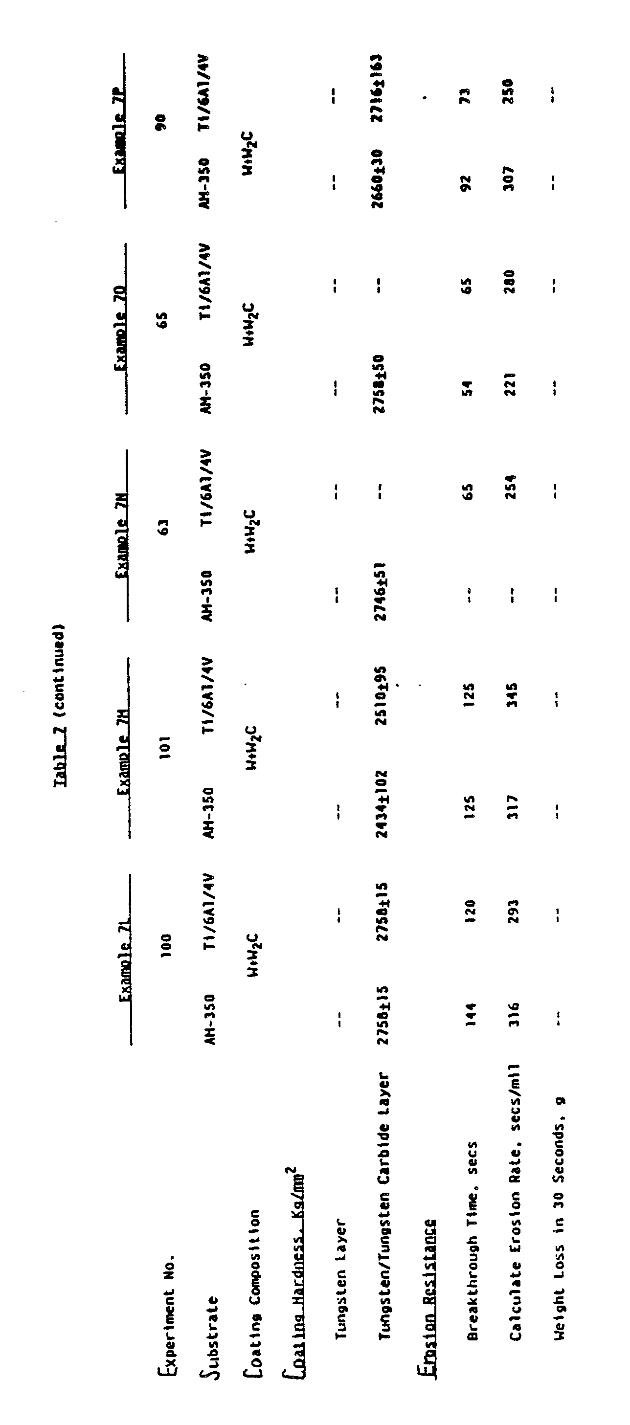
- This example showed that the erosion resistance of W+W₂C coating with a W interlayer was much better than that of W+W₃C and W+W₂C+W₃C coatings with a W interlayer. This is an unexpected and significant finding.
- In this example, several AM-350, Ti/6Al/4V and IN-718 specimens were coated with W followed by W + W₂C coating using conditions summarized in Table 6. All the specimens were coated with ∼6 µm and ∼15 µm W and W+W₂C layers, respectively. The coating consisted of columnar W coating and non-columnar W+W₂C coating at the top of W. The thickness ratio was ∼0.4. The coating was smooth. However, a few fine cracks were noted in the coating, as shown in the Figure 12. The erosion resistance of the coating shown in Table 7 was similar to that noted in Example 7A. The weight loss during erosion test was determined and presented in Table 7. The weight loss was slightly higher in this example than that observed with W+W₂C+W₃C coating with W interlayer. This could be related to the fact the cracks in W + W₂C coatings were slightly wider than those noted in W + W₂C + W₃C coating.
- Examples 7A and 7B clearly showed that a tungsten to tungsten/tungsten carbide thickness ratio of ∼0.35 is sufficient enough to give a maximum erosion resistance.
- The CVD run described in Example 7B was repeated to provide slightly higher thickness ratio. The thickness of W + W₂C layer varied from 10 µm to 11 µm on various substrates, and the ratio varied from 0.44 to 0.50. The coating on AM-350 and IN-718 was crack-free; whereas, a few fine cracks were observed on Ti/6Al/4V. This indicated that crack-free coating on AM-350 and IN-718 can be obtained by providing ∼5 µm thick W and ∼10 to 11 µm thick W + W₂C layers. These thickness values, however, were not good enough to give crack-free coating on Ti/6Al/4V. The erosion resistance of the coating was very good as shown in Table 7.
- The CVD run described in Example 7C was repeated to provide slightly thicker W + W₂C layer while maintaining thickness ratio. Surprisingly, the coating on AM-350 and Ti/6Al/4V cracked. This information suggested that the thickness of W + W₂C layer was important to prevent cracks in the coating. The erosion resistance of the coating was good, as shown in Table 7.
- The CVD run described in Example 70 was repeated to provide slightly thinner W + W₂C layer and slightly higher thickness ratio. The coating on AM-350, Ti/6Al/4V and IN-718 was absolutely crack-free (see Figure 13), certifying the importance of the thickness of W + W₂C. The unetched and etched cross-sectional views of the composite coatings are shown in the Figures 3 and 4. The etched cross-section presented in the Figure 4 showed columnar growth of the tungsten interlayer and the non-columnar growth of the tungsten/tungsten carbide layer. The etched cross-section of the coating also demonstrated the absence of any cracks in the coating. The erosion resistance of the coating was good, as shown in Table 7.
- The CVD run described in Example 7E was repeated in these examples to verify the concept of crack-free coating. The coatings obtained in these runs were absolutely crack-free. They also had good erosion resistance, as shown in Table 7.
- In this example, the thickness of W and W + W₂C layers was slightly increased on AM-350 stainless steel to determine its effect on cracks. The thickness ratio obtained was ∼0.6. The coating on AM-350 cracked and that on Ti/6Al/4V did not. The coating on AM-350 cracked probably because of the thicker W + W₂C layer. This information further confirmed the statement made earlier that the thickness of W + W₂C layer played an important role in obtaining crack-free coating. Erosion resistance of the coating was good, as shown in Table 7.
- To further demonstrate the effect of W + W₂C coating thickness on cracks, a CVD run was carried out to obtain a thicker W + W₂C coating and a higher thickness ratio. Despite higher thickness ratio the coating on all the specimens cracked. This example, therefore, confirmed the importance of the thickness of W + W₂C layer for preventing cracks in the coating. The erosion resistance of the coating was good, as expected.
- To further demonstrate the effect of W + W₂C coating thickness on cracks, one more CVD run was conducted to obtain thicker W + W₂C coating and higher thickness ratio. Once again, coating cracked. The erosion resistance of the coating, however, was still good.
- Several CVD runs were conducted to vary thicknesses of W and W + W₂C layers and thickness ratios. These experiments were conducted to effectively map out the crack-free and cracked coating region. The data summarized in Table 6 showed that as long as the thickness of W + W₂C layer was maintained below ∼13.5 µm and thickness ratio maintained above 0.6 the coating obtained was absolutely crack-free. The coating in all the cases demonstrated good erosion resistance, as shown in Table 7.
- The erosion resistance of W+W₂C coating is either equivalent to or superior to the erosion resistance of W+W₂C+W₃C. The erosion resistance of W+W₂C is independent of the thickness of the tungsten interlayer when the ratio of the W to the W+W₂C thickness is at least 0.35.
- Careful control of both the thickness of the tungsten/tungsten carbide coating and the ratio of the thicknesses of W to W+W₂C is required to obtain a crack-free coating. For both AM-350 and Ti/6Al/4V, the maximum thickness for producing a crack-free coating is about 14 µm. The critical thickness ratio for a crack-free coating is about 0.4 and 0.5 for AM-350 and Ti/6Al/4V, respectively.
- The wear performance of the uncoated stainless steel 1" diameter SS-422 disc was determined using a ball-on-disc test in the presence and absence of a lubricant. The non-lubricated wear test was conducted in dry air (1% relative humidity) and saturated air (99% relative humidity). The lubricated wear test was conducted in the presence of a cutting fluid consisting of an emulsion of 20% mineral oil in water. The ball used in the test was made of 52-100 chrome steel. The ball-on-disc wear test was performed using a load of 5 Newton, ambient temperature, stationary ball on rotating disc at a speed of 10 cm/sec., and for approximately 0.3 kilometer. The wear performance was determined by measuring the combined volumetric material loss of the ball and disc. Th wear rate was very high in the dry air (1% relative humidity), as shown in the Table 8. The wear rate in the saturated air (99% relative humidity) and cutting fluid, on the other hand, was considerably lower, with the rate being lowest in the presence of the lubricant.
- In this example, a two-step coating process was used. Several SS-422 discs were heated to a temperature of bout 460°C in the presence of flowing argon and at the reaction temperature a gaseous mixture of 300 cc/min WF₆, 3,000 cc/min hydrogen, and 4,500 cc/min of argon was passed into the furnace over the specimens for 15 minutes to coat them with tungsten. After coating the specimens with tungsten for 15 minutes, a gaseous mixture of 300 cc/min WF₆, 3,000 cc/min hydrogen, 300 cc/min argon and 40 cc/min of DME was passed into the furnace for 30 minutes to provide tungsten/tungsten carbide coating. A total pressure was maintained at 40 Torr during the tungsten as well as tungsten/tungsten carbide coating steps.
- The SS-422 discs were coated with 10.4 µm thick tungsten followed by 12.4 µm thick tungsten/tungsten carbide. The tungsten/tungsten carbide top coat consisted of a mixture of W and W₃C phases. The hardness of the top coat was approximately 2450 Vickers. The coating was smooth and had a few very fine interconnected cracks.
- The wear performance of the coated SS-422 disc was determined using ball-on-disc test described in the Example 8 in the presence of 1% and 99% relative humidity and cutting fluid as a lubricant. The wear rate data summarized in the Table 8 showed dramatically lower wear rate in the presence of dry air (1% relative humidity) compared to the uncoated disc. The wear rate in the presence of 99% relative humidity and cutting fluid was also lower than the uncoated disc.
- This example, therefore, shows that a composite coating is very effective in reducing the total wear rate in the presence and absence of a lubricant.
- In this example, a two-step coating process was used again. Several SS-422 discs were heated to a temperature of about 460°C in the presence of flowing argon and at the reaction temperature a gaseous mixture of 300 cc/min WF₆, 3,000 cc/min hydrogen, and 4,500 cc/min of argon was passed into the furnace over the specimens for 15 minutes to coat them with tungsten. After coating the specimens with tungsten for 15 minutes, a gaseous mixture of 300 cc/min WF₆, 3,000 cc/min hydrogen, 300 cc/min argon and 60 cc/min of DME was passed into the furnace for 40 minutes to provide tungsten/tungsten carbide coating. A total pressure was maintained at 40 Torr during the tungsten as well as tungsten/tungsten carbide coating steps.
- The SS-422 discs were coated with 9.7 µm thick tungsten followed by 14.0 µm thick tungsten/tungsten carbide. The tungsten/tungsten carbide top coat consisted of a mixture of W, W₂C and W₃C phases. It had a hardness of approximately 2250 Vickers. The coating was smooth and had a few extremely fine and long cracks.
Table 8 Example No. Composition of the Tungsten/Tungsten Carbide Top Coat Total Wear Rate. 10⁻¹⁵m²/N 1% Humidity 99% Humidity Cutting Fluid Example 8 -- 327 8.1 2.9 Example 9 W+W₃C 1.9 7.7 1.0 Example 10 W+W₂C+W₃C 1.0 4.7 0.9 Example 11 W+W₂C 1.40 3.6 1.0 - The wear performance of the coated SS-422 disc was determined using ball-on-disc test described in the Example 8 in the presence of 1% and 99% relative humidity and cutting fluid as a lubricant. The wear rate data summarized in the Table 8 showed lower wear rate in the presence of 1% and 99% relative humidity and cutting fluid compared to the uncoated disc and disc coated with tungsten followed by W+W₃C coating.
- This example shows that a composite coating is very effective in improving wear performance of the SS-422 disc. It also shows that the wear performance of the composite coating can be improved by adjusting the composition of the tungsten/tungsten carbide top coat.
- In this example, a two-step coating process was used again. Several SS-422 discs were heated to a temperature of about 460°C in the presence of flowing argon and at the reaction temperature a gaseous mixture of 300 cc/min WF₆, 3,000 cc/min hydrogen, and 4,500 cc/min of argon was passed into the furnace over the specimens for 15 minutes to coat them with tungsten. After coating the specimens with tungsten for 15 minutes, a gaseous mixture of 300 cc/min WF₆, 3,000 cc/min hydrogen, 300 cc/min argon and 80 cc/min of DME was passed into the furnace for 40 minutes to provide tungsten/tungsten carbide coating. A total pressure was maintained at 40 Torr during the tungsten as well as tungsten/tungsten carbide coating steps.
- The SS-422 discs were coated with 10 µm thick tungsten followed by 13.0 µm thick tungsten/tungsten carbide. The tungsten/tungsten carbide top coat consisted of a mixture of W and W₂C phases. It had a hardness of approximately 2750 Vickers. The coating was smooth and crack-free.
- The wear performance of the coated SS-422 disc was determined using ball-on-disc test described in Example 8 in the presence of 1% and 99% relative humidity and cutting fluid as a lubricant. The wear rate data summarized in Table 8 showed the wear rate was similar to that noted with the other composite coatings (i.e., W+W₃C and W+W₂C+W₃C coatings) in the presence of dry air (1% relative humidity) and cutting fluid. The wear rate, however, was lower compared to other composite coatings in the presence of 99% relative humidity.
- This example shows that a composite coating is very effective in improving wear performance of the SS-422 disc.
- The wear data presented in Examples 8 to 11 clearly demonstrate that a composite tungsten followed by tungsten/tungsten carbide coating can be used to significantly reduce the abrasive wear rate and concomitantly increase the life of the stainless steel material in the dry, humid and lubricated environments. The data presented in Examples 1 to 4 show that the composite coating is very effective in reducing the erosive wear rate of the ferrous and non-ferrous alloys. Additionally, Examples 1 to 4 show that an interlayer of tungsten is required to improve the performance of the tungsten/tungsten carbide coating. This is an unexpected finding.
- The relationship between the ratio of the thickness of the tungsten interlayer to the thickness of the tungsten-carbon alloy (tungsten/tungsten carbide coating) is elaborated further in the Figure 14. It shows that for W+W₃C top coat the erosion resistance measured as secs/mil increases with increasing the thickness ratio. A thickness ratio greater than 0.3 is required to significantly increase the erosion resistance of the W+W₃C coating system. Furthermore, a thickness ratio of about 0.6 is required to obtain optimum erosion resistance of the W+W₃C coating system. Figure 14 also shows that a thickness ratio of greater than 0.3 is required for significantly increasing the erosion resistance of the W+W₂C+W₃C coating system. It also shows that a thickness ratio of about 0.35 yields optimum erosion performance both for the W+W₂C+W₃C and W+W₂C coating systems. This thickness ratio to obtain optimum erosion resistance is considerably lower for the W+W₂C+W₃C and W+W₂C coating systems than the W+W₃C coating system.
- The relationship between the thickness of the tungsten-carbon alloy and the ratio of the thickness of the tungsten interlayer to the thickness of the tungsten-carbon alloy (tungsten/tungsten carbide coating) is presented in Figure 15. It shows a very narrow region for obtaining a crack-free W+W₃C coating system. A thin W+W₃C layer is required to achieve a crack-free coating. Compared to the W+W₃C coating system, the W+W₂C+W₃C and W+W₂C coating systems provide a wider crack-free coating region.
- It is worth noting that a thicker crack-free tungsten/tungsten carbide coating can be obtained for W+W₂C top coat than is possible for W+W₂C+W₃C or for W+W₃C. In addition, the thickness of the tungsten interlayer which is required to achieve a crack-free coating is significantly lower for W+W₂C than for W+W₂C+W₃C or W+W₃C. By reducing the thickness of the W interlayer, the overall thickness of the composite coating which is required to provide a specified erosive wear life or abrasive wear life can be minimized by going progressively from W+W₃C to W+W₂C+W₃C and to W+W₂C composite coating system.
- One particularly important use of the composite coating system according to the present invention is to provide highly erosive and abrasive wear resistant coatings on ferrous, non-ferrous and titanium alloy compressor blades for gas turbines and jet engines.
Claims (20)
Applications Claiming Priority (2)
| Application Number | Priority Date | Filing Date | Title |
|---|---|---|---|
| US07/153,738 US4855188A (en) | 1988-02-08 | 1988-02-08 | Highly erosive and abrasive wear resistant composite coating system |
| US153738 | 1988-02-08 |
Publications (3)
| Publication Number | Publication Date |
|---|---|
| EP0328084A2 true EP0328084A2 (en) | 1989-08-16 |
| EP0328084A3 EP0328084A3 (en) | 1989-10-25 |
| EP0328084B1 EP0328084B1 (en) | 1993-10-06 |
Family
ID=22548536
Family Applications (1)
| Application Number | Title | Priority Date | Filing Date |
|---|---|---|---|
| EP89102176A Expired - Lifetime EP0328084B1 (en) | 1988-02-08 | 1989-02-08 | Highly erosive and abrasive wear resistant composite coating system |
Country Status (9)
| Country | Link |
|---|---|
| US (1) | US4855188A (en) |
| EP (1) | EP0328084B1 (en) |
| JP (1) | JPH0784661B2 (en) |
| KR (1) | KR890013218A (en) |
| AU (1) | AU602284B2 (en) |
| CA (1) | CA1333139C (en) |
| DE (1) | DE68909629T2 (en) |
| DK (1) | DK54489A (en) |
| IL (1) | IL89153A0 (en) |
Cited By (8)
| Publication number | Priority date | Publication date | Assignee | Title |
|---|---|---|---|---|
| EP0386658A2 (en) * | 1989-03-07 | 1990-09-12 | Air Products And Chemicals, Inc. | Wear resistant coating for sharp-edged tools and the like |
| EP0538389A1 (en) * | 1990-07-12 | 1993-04-28 | SARIN, Vinod K. | Abrasion resistant coated articles |
| GB2308133A (en) * | 1995-12-13 | 1997-06-18 | Kennametal Inc | Cutting tool with coating of boron carbide or tungsten carbide for machining titanium |
| GB2323856A (en) * | 1997-03-12 | 1998-10-07 | Kennametal Inc | Cutting tool for milling titanium and titanium alloys |
| FR2764310A1 (en) * | 1997-06-10 | 1998-12-11 | Commissariat Energie Atomique | MULTI-LAYERED MATERIAL WITH ANTI-EROSION, ANTI-ABRASION, AND ANTI-WEAR COATING ON AN ALUMINUM, MAGNESIUM OR ALLOY SUBSTRATE |
| US6228483B1 (en) | 1990-07-12 | 2001-05-08 | Trustees Of Boston University | Abrasion resistant coated articles |
| US9740832B2 (en) | 2010-07-23 | 2017-08-22 | Apple Inc. | Method, apparatus and system for access mode control of a device |
| US10078439B2 (en) | 2005-12-23 | 2018-09-18 | Apple Inc. | Unlocking a device by performing gestures on an unlock image |
Families Citing this family (15)
| Publication number | Priority date | Publication date | Assignee | Title |
|---|---|---|---|---|
| US5262202A (en) * | 1988-02-17 | 1993-11-16 | Air Products And Chemicals, Inc. | Heat treated chemically vapor deposited products and treatment method |
| US4873152A (en) * | 1988-02-17 | 1989-10-10 | Air Products And Chemicals, Inc. | Heat treated chemically vapor deposited products |
| US4997324A (en) * | 1988-04-21 | 1991-03-05 | Toshiba Kikai Kabushiki Kaisha | Spindle structure for machine tool |
| FR2638781B1 (en) * | 1988-11-09 | 1990-12-21 | Snecma | ELECTROPHORETIC ANTI-WEAR DEPOSITION OF THE CONSOLIDATED METALLOCERAMIC TYPE BY ELECTROLYTIC NICKELING |
| US5277987A (en) * | 1991-02-01 | 1994-01-11 | Air Products And Chemicals, Inc. | High hardness fine grained beta tungsten carbide |
| EP0562108B1 (en) * | 1991-10-14 | 1996-12-27 | Commissariat A L'energie Atomique | Multi-layer material for anti-erosion and anti-abrasion coating |
| US5702829A (en) * | 1991-10-14 | 1997-12-30 | Commissariat A L'energie Atomique | Multilayer material, anti-erosion and anti-abrasion coating incorporating said multilayer material |
| JP3417591B2 (en) * | 1992-05-19 | 2003-06-16 | 株式会社リコー | Stencil printing machine and stencil making machine |
| JPH0680896U (en) * | 1993-04-23 | 1994-11-15 | 日本カーター株式会社 | Bearing device for multi-stage submerged motor pump |
| US5560839A (en) * | 1994-06-27 | 1996-10-01 | Valenite Inc. | Methods of preparing cemented metal carbide substrates for deposition of adherent diamond coatings and products made therefrom |
| WO2002044437A2 (en) | 2000-11-02 | 2002-06-06 | Composite Tool Company, Inc. | High strength alloys and methods for making same |
| EP1982803A1 (en) * | 2007-04-16 | 2008-10-22 | Koninklijke Philips Electronics N.V. | Cutting eleemnt, electric shaver provided with a cutting element and method for producing such element |
| EP2947592B1 (en) | 2007-09-24 | 2021-10-27 | Apple Inc. | Embedded authentication systems in an electronic device |
| WO2022130706A1 (en) * | 2020-12-16 | 2022-06-23 | 住友電工ハードメタル株式会社 | Cutting tool |
| CN114875355B (en) * | 2022-04-20 | 2023-08-18 | 西安致远航空科技有限公司 | Preparation process of composite protective coating on surface of die |
Citations (5)
| Publication number | Priority date | Publication date | Assignee | Title |
|---|---|---|---|---|
| US3574672A (en) * | 1964-08-05 | 1971-04-13 | Texas Instruments Inc | Cvd process for producing tungsten carbide and article of manufacture |
| US3951612A (en) * | 1974-11-12 | 1976-04-20 | Aerospace Materials Inc. | Erosion resistant coatings |
| FR2331390A1 (en) * | 1975-11-14 | 1977-06-10 | Fulmer Res Inst Ltd | Tungsten carbide and nickel phosphide coated die - with longer life for aluminium extrusion |
| US4147820A (en) * | 1976-07-06 | 1979-04-03 | Chemetal Corporation | Deposition method and products |
| WO1983000481A1 (en) * | 1981-08-03 | 1983-02-17 | Dart Ind Inc | High hardness material |
Family Cites Families (5)
| Publication number | Priority date | Publication date | Assignee | Title |
|---|---|---|---|---|
| US3389977A (en) * | 1964-08-05 | 1968-06-25 | Texas Instruments Inc | Tungsten carbide coated article of manufacture |
| US4741975A (en) * | 1984-11-19 | 1988-05-03 | Avco Corporation | Erosion-resistant coating system |
| US4761346A (en) * | 1984-11-19 | 1988-08-02 | Avco Corporation | Erosion-resistant coating system |
| US4874642A (en) * | 1987-09-03 | 1989-10-17 | Air Products And Chemicals, Inc. | Method for depositing a hard, fine-grained, non-columnar alloy of tungsten and carbon on a substrate |
| US4873152A (en) * | 1988-02-17 | 1989-10-10 | Air Products And Chemicals, Inc. | Heat treated chemically vapor deposited products |
-
1988
- 1988-02-08 US US07/153,738 patent/US4855188A/en not_active Expired - Fee Related
-
1989
- 1989-02-01 AU AU28958/89A patent/AU602284B2/en not_active Expired - Fee Related
- 1989-02-02 IL IL89153A patent/IL89153A0/en unknown
- 1989-02-02 CA CA000589920A patent/CA1333139C/en not_active Expired - Fee Related
- 1989-02-07 DK DK054489A patent/DK54489A/en not_active Application Discontinuation
- 1989-02-08 KR KR1019890001389A patent/KR890013218A/en not_active Application Discontinuation
- 1989-02-08 JP JP1029570A patent/JPH0784661B2/en not_active Expired - Lifetime
- 1989-02-08 EP EP89102176A patent/EP0328084B1/en not_active Expired - Lifetime
- 1989-02-08 DE DE89102176T patent/DE68909629T2/en not_active Expired - Fee Related
Patent Citations (5)
| Publication number | Priority date | Publication date | Assignee | Title |
|---|---|---|---|---|
| US3574672A (en) * | 1964-08-05 | 1971-04-13 | Texas Instruments Inc | Cvd process for producing tungsten carbide and article of manufacture |
| US3951612A (en) * | 1974-11-12 | 1976-04-20 | Aerospace Materials Inc. | Erosion resistant coatings |
| FR2331390A1 (en) * | 1975-11-14 | 1977-06-10 | Fulmer Res Inst Ltd | Tungsten carbide and nickel phosphide coated die - with longer life for aluminium extrusion |
| US4147820A (en) * | 1976-07-06 | 1979-04-03 | Chemetal Corporation | Deposition method and products |
| WO1983000481A1 (en) * | 1981-08-03 | 1983-02-17 | Dart Ind Inc | High hardness material |
Cited By (18)
| Publication number | Priority date | Publication date | Assignee | Title |
|---|---|---|---|---|
| EP0386658A2 (en) * | 1989-03-07 | 1990-09-12 | Air Products And Chemicals, Inc. | Wear resistant coating for sharp-edged tools and the like |
| EP0386658A3 (en) * | 1989-03-07 | 1990-10-10 | Air Products And Chemicals, Inc. | Wear resistant coating for sharp-edged tools and the like |
| EP0538389A1 (en) * | 1990-07-12 | 1993-04-28 | SARIN, Vinod K. | Abrasion resistant coated articles |
| EP0538389A4 (en) * | 1990-07-12 | 1994-03-23 | Vinod K. Sarin | |
| US6228483B1 (en) | 1990-07-12 | 2001-05-08 | Trustees Of Boston University | Abrasion resistant coated articles |
| GB2308133A (en) * | 1995-12-13 | 1997-06-18 | Kennametal Inc | Cutting tool with coating of boron carbide or tungsten carbide for machining titanium |
| US5718541A (en) * | 1995-12-13 | 1998-02-17 | Kennametal Inc. | Cutting tool for machining titanium and titanium alloys |
| GB2308133B (en) * | 1995-12-13 | 2000-06-21 | Kennametal Inc | Cutting tool for machining titanium and titanium alloys |
| US5984593A (en) * | 1997-03-12 | 1999-11-16 | Kennametal Inc. | Cutting insert for milling titanium and titanium alloys |
| GB2323856A (en) * | 1997-03-12 | 1998-10-07 | Kennametal Inc | Cutting tool for milling titanium and titanium alloys |
| GB2323856B (en) * | 1997-03-12 | 2002-03-13 | Kennametal Inc | Cutting insert for milling titanium and titanium alloys |
| FR2764310A1 (en) * | 1997-06-10 | 1998-12-11 | Commissariat Energie Atomique | MULTI-LAYERED MATERIAL WITH ANTI-EROSION, ANTI-ABRASION, AND ANTI-WEAR COATING ON AN ALUMINUM, MAGNESIUM OR ALLOY SUBSTRATE |
| US6159618A (en) * | 1997-06-10 | 2000-12-12 | Commissariat A L'energie Atomique | Multi-layer material with an anti-erosion, anti-abrasion, and anti-wear coating on a substrate made of aluminum, magnesium or their alloys |
| US10078439B2 (en) | 2005-12-23 | 2018-09-18 | Apple Inc. | Unlocking a device by performing gestures on an unlock image |
| US10754538B2 (en) | 2005-12-23 | 2020-08-25 | Apple Inc. | Unlocking a device by performing gestures on an unlock image |
| US11086507B2 (en) | 2005-12-23 | 2021-08-10 | Apple Inc. | Unlocking a device by performing gestures on an unlock image |
| US11669238B2 (en) | 2005-12-23 | 2023-06-06 | Apple Inc. | Unlocking a device by performing gestures on an unlock image |
| US9740832B2 (en) | 2010-07-23 | 2017-08-22 | Apple Inc. | Method, apparatus and system for access mode control of a device |
Also Published As
| Publication number | Publication date |
|---|---|
| AU602284B2 (en) | 1990-10-04 |
| US4855188A (en) | 1989-08-08 |
| KR890013218A (en) | 1989-09-22 |
| IL89153A0 (en) | 1989-09-10 |
| AU2895889A (en) | 1989-08-10 |
| JPH01246363A (en) | 1989-10-02 |
| DK54489A (en) | 1989-08-09 |
| DK54489D0 (en) | 1989-02-07 |
| EP0328084B1 (en) | 1993-10-06 |
| EP0328084A3 (en) | 1989-10-25 |
| JPH0784661B2 (en) | 1995-09-13 |
| DE68909629T2 (en) | 1994-02-10 |
| DE68909629D1 (en) | 1993-11-11 |
| CA1333139C (en) | 1994-11-22 |
Similar Documents
| Publication | Publication Date | Title |
|---|---|---|
| EP0328084B1 (en) | Highly erosive and abrasive wear resistant composite coating system | |
| EP1209255B1 (en) | Oxide coated cutting tool | |
| US4927713A (en) | High erosion/wear resistant multi-layered coating system | |
| JP5363445B2 (en) | Cutting tools | |
| KR960015546B1 (en) | Diffusion barrier coating material | |
| US4945640A (en) | Wear resistant coating for sharp-edged tools and the like | |
| US4902535A (en) | Method for depositing hard coatings on titanium or titanium alloys | |
| US4741975A (en) | Erosion-resistant coating system | |
| US4931152A (en) | Method for imparting erosion-resistance to metallic substrate | |
| US5024901A (en) | Method for depositing highly erosive and abrasive wear resistant composite coating system on a substrate | |
| JPH026314A (en) | High-hardness particulate tungsten-carbon alloy and manufacture thereof | |
| US4990372A (en) | Method for producing wear resistant internal surfaces of structures | |
| US5262202A (en) | Heat treated chemically vapor deposited products and treatment method | |
| US4873152A (en) | Heat treated chemically vapor deposited products | |
| US5006371A (en) | Low temperature chemical vapor deposition method for forming tungsten and tungsten carbide | |
| EP1262576B1 (en) | CVD Al2O3 coated cutting tool | |
| US4910091A (en) | High hardness fine grained tungsten-carbon alloys | |
| US5064728A (en) | Article with internal wear resistant surfaces | |
| KR960006051B1 (en) | Method for coating a thin film of diamond for a cutting tool | |
| Aguero et al. | A Low Temperature CVD Process for TiN Coatings | |
| AGUERO | A LOW TEMPERATURE CVD PROCESS FOR TiN COATINGS A. AGUERO, D. LITTLE AND P. LOWDEN |
Legal Events
| Date | Code | Title | Description |
|---|---|---|---|
| PUAI | Public reference made under article 153(3) epc to a published international application that has entered the european phase |
Free format text: ORIGINAL CODE: 0009012 |
|
| AK | Designated contracting states |
Kind code of ref document: A2 Designated state(s): AT BE CH DE ES FR GB IT LI LU NL SE |
|
| PUAL | Search report despatched |
Free format text: ORIGINAL CODE: 0009013 |
|
| AK | Designated contracting states |
Kind code of ref document: A3 Designated state(s): AT BE CH DE ES FR GB IT LI LU NL SE |
|
| 17P | Request for examination filed |
Effective date: 19900412 |
|
| 17Q | First examination report despatched |
Effective date: 19911104 |
|
| RBV | Designated contracting states (corrected) |
Designated state(s): CH DE FR GB LI |
|
| GRAA | (expected) grant |
Free format text: ORIGINAL CODE: 0009210 |
|
| AK | Designated contracting states |
Kind code of ref document: B1 Designated state(s): CH DE FR GB LI |
|
| REF | Corresponds to: |
Ref document number: 68909629 Country of ref document: DE Date of ref document: 19931111 |
|
| ET | Fr: translation filed | ||
| PLBE | No opposition filed within time limit |
Free format text: ORIGINAL CODE: 0009261 |
|
| STAA | Information on the status of an ep patent application or granted ep patent |
Free format text: STATUS: NO OPPOSITION FILED WITHIN TIME LIMIT |
|
| 26N | No opposition filed | ||
| PGFP | Annual fee paid to national office [announced via postgrant information from national office to epo] |
Ref country code: GB Payment date: 19960111 Year of fee payment: 8 |
|
| PGFP | Annual fee paid to national office [announced via postgrant information from national office to epo] |
Ref country code: FR Payment date: 19960215 Year of fee payment: 8 |
|
| PGFP | Annual fee paid to national office [announced via postgrant information from national office to epo] |
Ref country code: DE Payment date: 19960227 Year of fee payment: 8 |
|
| PGFP | Annual fee paid to national office [announced via postgrant information from national office to epo] |
Ref country code: CH Payment date: 19960329 Year of fee payment: 8 |
|
| PG25 | Lapsed in a contracting state [announced via postgrant information from national office to epo] |
Ref country code: GB Effective date: 19970208 |
|
| PG25 | Lapsed in a contracting state [announced via postgrant information from national office to epo] |
Ref country code: LI Effective date: 19970228 Ref country code: CH Effective date: 19970228 |
|
| GBPC | Gb: european patent ceased through non-payment of renewal fee |
Effective date: 19970208 |
|
| REG | Reference to a national code |
Ref country code: CH Ref legal event code: PL |
|
| PG25 | Lapsed in a contracting state [announced via postgrant information from national office to epo] |
Ref country code: FR Effective date: 19971030 |
|
| PG25 | Lapsed in a contracting state [announced via postgrant information from national office to epo] |
Ref country code: DE Effective date: 19971101 |
|
| REG | Reference to a national code |
Ref country code: FR Ref legal event code: ST |