EP0329960A2 - Secured package integrity - Google Patents
Secured package integrity Download PDFInfo
- Publication number
- EP0329960A2 EP0329960A2 EP89101212A EP89101212A EP0329960A2 EP 0329960 A2 EP0329960 A2 EP 0329960A2 EP 89101212 A EP89101212 A EP 89101212A EP 89101212 A EP89101212 A EP 89101212A EP 0329960 A2 EP0329960 A2 EP 0329960A2
- Authority
- EP
- European Patent Office
- Prior art keywords
- network
- closure
- container
- package
- oscillatory
- Prior art date
- Legal status (The legal status is an assumption and is not a legal conclusion. Google has not performed a legal analysis and makes no representation as to the accuracy of the status listed.)
- Ceased
Links
Images


Classifications
-
- B—PERFORMING OPERATIONS; TRANSPORTING
- B65—CONVEYING; PACKING; STORING; HANDLING THIN OR FILAMENTARY MATERIAL
- B65D—CONTAINERS FOR STORAGE OR TRANSPORT OF ARTICLES OR MATERIALS, e.g. BAGS, BARRELS, BOTTLES, BOXES, CANS, CARTONS, CRATES, DRUMS, JARS, TANKS, HOPPERS, FORWARDING CONTAINERS; ACCESSORIES, CLOSURES, OR FITTINGS THEREFOR; PACKAGING ELEMENTS; PACKAGES
- B65D55/00—Accessories for container closures not otherwise provided for
- B65D55/02—Locking devices; Means for discouraging or indicating unauthorised opening or removal of closure
- B65D55/028—Locking devices; Means for discouraging or indicating unauthorised opening or removal of closure initial opening or unauthorised access being indicated by the presence or absence of an audible or electrical signal
-
- B—PERFORMING OPERATIONS; TRANSPORTING
- B65—CONVEYING; PACKING; STORING; HANDLING THIN OR FILAMENTARY MATERIAL
- B65D—CONTAINERS FOR STORAGE OR TRANSPORT OF ARTICLES OR MATERIALS, e.g. BAGS, BARRELS, BOTTLES, BOXES, CANS, CARTONS, CRATES, DRUMS, JARS, TANKS, HOPPERS, FORWARDING CONTAINERS; ACCESSORIES, CLOSURES, OR FITTINGS THEREFOR; PACKAGING ELEMENTS; PACKAGES
- B65D5/00—Rigid or semi-rigid containers of polygonal cross-section, e.g. boxes, cartons or trays, formed by folding or erecting one or more blanks made of paper
- B65D5/42—Details of containers or of foldable or erectable container blanks
- B65D5/4291—Containers provided with an acoustic device, e.g. for indicating opening of the package
-
- Y—GENERAL TAGGING OF NEW TECHNOLOGICAL DEVELOPMENTS; GENERAL TAGGING OF CROSS-SECTIONAL TECHNOLOGIES SPANNING OVER SEVERAL SECTIONS OF THE IPC; TECHNICAL SUBJECTS COVERED BY FORMER USPC CROSS-REFERENCE ART COLLECTIONS [XRACs] AND DIGESTS
- Y10—TECHNICAL SUBJECTS COVERED BY FORMER USPC
- Y10S—TECHNICAL SUBJECTS COVERED BY FORMER USPC CROSS-REFERENCE ART COLLECTIONS [XRACs] AND DIGESTS
- Y10S206/00—Special receptacle or package
- Y10S206/807—Tamper proof
Definitions
- This invention relates to the art of packaging and it has particular relationship to determining if a package which is assumed to be intact has been undesirably opened.
- This invention is applicable not only to bottles and boxes such as are used in the food, beverage and pharmaceutical industries, but, also, to sealed documents which may be classified or valuable.
- the word "package”, as used in this application, includes within its meaning not only bottles and boxes, but, also, sealed documents.
- Sharpe U.S. 4,398,089, is typical of the prior art. Sharpe discloses a container including a radiation shell shielded from radiation detectors by a shielding shell. Sharpe states that when the container is broken, the shielding shell is ruptured and the detector picks up the radiation actuating an alarm. This expedient involves the hazards of radioactivity. In addition, Sharpe does not describe what its radiation material is and what kind of radiation it emits. Gamma radiation would require a heavy lead shield. An alpha radiation emitter such as Pu238 also emits gamma rays. The gamma rays would be present inside and outside of the container and would require shielding.
- an electrical oscillatory network i.e., a tuned resonant network
- the network typically includes a one-turn spiral of conducting material overlapping at the inner and outer ends.
- This structure forms a one-turn inductance having a capacitance by reason of the overlapping ends, in parallel with the inductance, i.e., a parallel tuned network.
- the one-turn spiral is printed, by the methods of producing printed circuit boards, on a film of insulating material. The film seals the opening of the container.
- a dab of uncured adhesive is adhered to a region of the spiral. When the package is closed by the closure, the dab is engaged by the inner surface of the closure. After the adhesive is cured, the closure cannot be opened without tearing the electrically conducting spiral where the dab is adhered. The oscillatory network is thus broken.
- the capacitance is formed between the innermost and outermost turns.
- the intervening turns serve, in effect, to reduce the dielectric distance between the innermost and outermost turns which has the effect of increasing the capacitance.
- the package is monitored by a transmitter-receiver, typically under the counter over which the package is passed when purchased by a customer.
- the transmitter emits oscillation over a frequency band including the resonant frequency of the network. These oscillations are modulated by pulses.
- On the counter the electrical oscillatory network is in the field of the oscillations emitted by the transmitter.
- the oscillations are impressed on the network at the pulse intervals, each pulse transmitting energy to the network, exciting the network to emit a decaying pulse. After the transmission of the pulse ceases, the induced oscillations in the oscillatory network decay because of energy losses resulting from the network resistance and from electromagnetic radiation.
- the oscillatory network Since the oscillatory network has a high Q, the decaying oscillations persist for an appreciable interval and can be detected.
- the receiver For intact packages, the receiver produces a signal corresponding to the received pulse during the interval between transmitted pulses. Typically, the signal may be an audio signal corresponding to the pulse rate. If the package is opened and the oscillatory network has been broken, then no signal is produced, indicating that the package is not intact.
- the apparatus shown in Fig. 1 is a package 21 including a bottle 23 and a cap 25.
- the bottle is open at the top and includes an external thread 27 around its rim at the top.
- the thread 27 is engaged by mating internal thread along the lower rim of the cap 25.
- An electrical oscillatory network assembly 29 is interposed between the cap 25 and the bottle 23.
- the assembly 29 (Fig. 2) includes a film 31 of insulating material on which a one-turn spiral 33 of electrically conducting material is printed by a printed circuit process.
- the spiral 33 forms an inductance.
- the overlapping ends 35 and 37 of the spiral are insulated from each other and form a capacitance in parallel with the inductance.
- the spiral 33 and its overlapping ends 35-37 form an electrically oscillatory or parallel tuned network. It is desirable that the network 33-35-37 have a high Q and to achieve this purpose, the conductors forming the spiral 33 should be highly electrically conductive.
- the film 31 is sealed to the rim 39 bounding the opening in the bottle 23 after the content of the container is deposited therein.
- a dab 41 of uncured adhesive is deposited at a region of the spiral and the immediately surrounding film.
- the cap 25 is then threaded onto the thread 27 closing the bottle 23.
- the dab 41 of adhesive extends above the film 31 to an elevation at which it adheres to the inner surface of the cap 25 when the cap is threaded onto the bottle.
- the adhesive 41 is cured, the spiral 33 is adhered to the cap 25 so that removal of the cap breaks the tuned network.
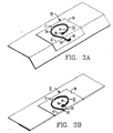
- Figs. 3A and 3B show another electrical oscillatory network assembly 50 in preliminary state and 51 in a finished state.
- This assembly includes a network 53 whose capacitance is higher than for the network shown in Figs. 1 and 2.
- a first step illustrated in Fig. 3A there is deposited on a film 55 of insulating material an electrically conducting configuration consisting of a loop 59 whose ends 61 and 63 overlap and are spaced a short distance from each other. The overlapping ends terminate in adjacent spaced conducting areas 65 and 66 which, preferably, are congruent.
- Fig. 3A shows another electrical oscillatory network assembly 50 in preliminary state and 51 in a finished state.
- This assembly includes a network 53 whose capacitance is higher than for the network shown in Figs. 1 and 2.
- an electrically conducting configuration consisting of a loop 59 whose ends 61 and 63 overlap and are spaced a short distance from each other.
- the overlapping ends terminate in
- the film 55 is folded along a line 67 between the areas 65 and 66 substantially bisecting the space between them so that the area 65 under the fold 67 is aligned with the area 66 above the fold.
- the areas 65 and 66 and the film between them form a capacitor whose dielectric is the two layers of film.
- a dab 71 of uncured adhesive is deposited over the loop 59 and the immediately adjacent film for physically connecting to a closing part, such as the cap 25 or a flap, so that the network 53 is broken when the closing part is opened.
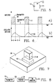
- the apparatus shown in Fig. 4 includes a box 81 having a body 82 closed by overlapping inner and outer flaps 83 and 85 and 87 and 89 respectively at its opposite ends.
- An electrical oscillatory assembly 51 as shown in Fig. 3B is adhered to flap 83 and an assembly 51a to flap 87.
- the flaps 85 and 89 are adhered to the dab 71.
- the unfolding of the flap 85 or 89 breaks the network 53 or 53a adhered to the opposite flap 83 or 87.
- the networks 53 and 53a are tuned to different frequencies which can be distinguished readily. The difference may be effected by dimensioning the areas 65 and 66 (Figs. 3A, 3B) of network 53 differently than the same areas for network 53a.
- Fig. 5 shows schematically a parallel tuned network 111 which corresponds to the networks 33-35-37 (Figs. 1, 2) and 53 and 53a (Figs. 3B and 4).
- This network 111 includes a capacitance 113 and an inductance 114 connected by a conductor 112. As shown, the capacitor typically has a capacity C of 10 ⁇ 10 Farads and an inductance L of 10 ⁇ 6 Henrys.
- the resonant frequency is For monitoring the package 21, the transmitter-receiver 103 includes a transmitter 115 which produces pulse modulated trains of oscillation 117 (Fig. 6a).
- the carrier oscillations are typically over a frequency band 10 peaking at 108 Hertz.
- the duty cycle of the pulses is 10% and the power output of the transmitter 115 is 0.1 milliwatt pulse power.
- the transmitter 115 and receiver 119 are constructed to produce alternate pulse modulated oscillations whose carriers peak at the different frequencies to which networks 53 and 53a are tuned. This enables the monitoring simultaneously both ends of the package 81 to determine if the flaps 83-85 or 87-89 have been opened.
- the package 21-81 is positioned typically about 1-foot from the transmitter 115 in the field of output of the transmitter.
- the receiver 119 is blocked during the transmitter pulse 117 (Fig. 6a) and is gated having a nominal threshold typically of 1 microwatt at 108 Hertz.
- the capacitor 113 is charged and the network 33-35-37 or 53 or 53a is set into oscillation producing decaying oscillations 120 (Fig. 6b).
- the resulting omissions are received and detected by the receiver 119, following the interval during which each transmitter pulse is blocked, thus producing a train of decaying pulses 120 (Fig. 6b) having trailing ends.
- the trailing ends constitute a train of detectable emissions picked up by the receiver.
- the transmitter-receiver 103 includes an audio or visible indicator 123 (Fig. 8). If the package 21-81 is intact, the indicator 123 produces a signal corresponding to the train of detected emissions, if not, no signal is produced. This process may be reversed.
- the indicator may be set to produce a signal when a break is detected in the package 21-81.
- the detector may be gated, for example, by a normally-open microswitch under the counter, which is closed by a package 21-81 when it is placed on the counter.
Abstract
Description
- This invention relates to the art of packaging and it has particular relationship to determining if a package which is assumed to be intact has been undesirably opened. This invention is applicable not only to bottles and boxes such as are used in the food, beverage and pharmaceutical industries, but, also, to sealed documents which may be classified or valuable. The word "package", as used in this application, includes within its meaning not only bottles and boxes, but, also, sealed documents.
- Sharpe, U.S. 4,398,089, is typical of the prior art. Sharpe discloses a container including a radiation shell shielded from radiation detectors by a shielding shell. Sharpe states that when the container is broken, the shielding shell is ruptured and the detector picks up the radiation actuating an alarm. This expedient involves the hazards of radioactivity. In addition, Sharpe does not describe what its radiation material is and what kind of radiation it emits. Gamma radiation would require a heavy lead shield. An alpha radiation emitter such as Pu238 also emits gamma rays. The gamma rays would be present inside and outside of the container and would require shielding.
- It is an object of this invention to overcome the disadvantages of the prior art and to provide for monitoring the integrity of packages without relying on radiation material.
- In accordance with this invention, an electrical oscillatory network, i.e., a tuned resonant network, without a power supply is connected between the closure of a package or container and the body of a package. The network typically includes a one-turn spiral of conducting material overlapping at the inner and outer ends. This structure forms a one-turn inductance having a capacitance by reason of the overlapping ends, in parallel with the inductance, i.e., a parallel tuned network. The one-turn spiral is printed, by the methods of producing printed circuit boards, on a film of insulating material. The film seals the opening of the container. A dab of uncured adhesive is adhered to a region of the spiral. When the package is closed by the closure, the dab is engaged by the inner surface of the closure. After the adhesive is cured, the closure cannot be opened without tearing the electrically conducting spiral where the dab is adhered. The oscillatory network is thus broken.
- The use of a multi-turn spiral is also within the scope of equivalents of this invention. In this case, the capacitance is formed between the innermost and outermost turns. The intervening turns serve, in effect, to reduce the dielectric distance between the innermost and outermost turns which has the effect of increasing the capacitance.
- The package is monitored by a transmitter-receiver, typically under the counter over which the package is passed when purchased by a customer. The transmitter emits oscillation over a frequency band including the resonant frequency of the network. These oscillations are modulated by pulses. On the counter the electrical oscillatory network is in the field of the oscillations emitted by the transmitter. The oscillations are impressed on the network at the pulse intervals, each pulse transmitting energy to the network, exciting the network to emit a decaying pulse. After the transmission of the pulse ceases, the induced oscillations in the oscillatory network decay because of energy losses resulting from the network resistance and from electromagnetic radiation. Since the oscillatory network has a high Q, the decaying oscillations persist for an appreciable interval and can be detected. For intact packages, the receiver produces a signal corresponding to the received pulse during the interval between transmitted pulses. Typically, the signal may be an audio signal corresponding to the pulse rate. If the package is opened and the oscillatory network has been broken, then no signal is produced, indicating that the package is not intact.
- For a better understanding of this invention, as described in the claims, reference is made to the following description taken in connection with the accompanying drawings, in which:
- Figure 1 is an exploded view in isometric of apparatus embodying this invention and for practicing the method of this invention;
- Fig. 2 is a partially diagrammatic view in isometric of an electrical oscillatory network assembly included in the apparatus shown in Fig. 1;
- Fig. 3A is a partially diagrammatic view in isometric showing the first step in the formation of another electrical oscillatory network assembly;
- Fig. 3B is a partially diagrammatic view in isometric showing a succeeding and final step in the formation of this other electrical oscillatory network assembly;
- Fig. 4 is a generally diagrammatic view in isometric showing an embodiment and practice of this invention for monitoring the integrity of a package closed by flaps;
- Fig. 5 is a schematic illustrating an electric oscillatory network used in the practice of this invention;
- Figs. 6(a) and (b) together constitute a graph illustrating the operation of this invention; and
- Figs. 7 and 8 are block diagrams for showing the manner in which a package is monitored in the practice of this invention.
- The apparatus shown in Fig. 1 is a
package 21 including abottle 23 and acap 25. The bottle is open at the top and includes anexternal thread 27 around its rim at the top. Thethread 27 is engaged by mating internal thread along the lower rim of thecap 25. An electricaloscillatory network assembly 29 is interposed between thecap 25 and thebottle 23. The assembly 29 (Fig. 2) includes afilm 31 of insulating material on which a one-turn spiral 33 of electrically conducting material is printed by a printed circuit process. Thespiral 33 forms an inductance. Theoverlapping ends spiral 33 and its overlapping ends 35-37 form an electrically oscillatory or parallel tuned network. It is desirable that the network 33-35-37 have a high Q and to achieve this purpose, the conductors forming thespiral 33 should be highly electrically conductive. - The
film 31 is sealed to therim 39 bounding the opening in thebottle 23 after the content of the container is deposited therein. Adab 41 of uncured adhesive is deposited at a region of the spiral and the immediately surrounding film. Thecap 25 is then threaded onto thethread 27 closing thebottle 23. Thedab 41 of adhesive extends above thefilm 31 to an elevation at which it adheres to the inner surface of thecap 25 when the cap is threaded onto the bottle. When thereafter theadhesive 41 is cured, thespiral 33 is adhered to thecap 25 so that removal of the cap breaks the tuned network. - Figs. 3A and 3B show another electrical
oscillatory network assembly 50 in preliminary state and 51 in a finished state. This assembly includes anetwork 53 whose capacitance is higher than for the network shown in Figs. 1 and 2. As a first step illustrated in Fig. 3A, there is deposited on afilm 55 of insulating material an electrically conducting configuration consisting of aloop 59 whoseends areas film 55 is folded along aline 67 between theareas area 65 under thefold 67 is aligned with thearea 66 above the fold. Theareas dab 71 of uncured adhesive is deposited over theloop 59 and the immediately adjacent film for physically connecting to a closing part, such as thecap 25 or a flap, so that thenetwork 53 is broken when the closing part is opened. - The apparatus shown in Fig. 4 includes a
box 81 having a body 82 closed by overlapping inner andouter flaps oscillatory assembly 51 as shown in Fig. 3B is adhered toflap 83 and anassembly 51a toflap 87. After thebox 81 is filled with its content, theflaps dab 71. When thebox 81 is opened at either end, the unfolding of theflap network opposite flap networks areas 65 and 66 (Figs. 3A, 3B) ofnetwork 53 differently than the same areas fornetwork 53a. - Packages such as 21 (Fig. 1) or 81 (Fig. 4) are monitored as they are passed over the counter 101 (Fig. 7) where a purchase is processed. Under the top of the
counter 101, there is a transmitter-receiver 103. The monitoring can be understood by consideration of Figs. 5 and 6. Fig. 5 shows schematically a parallel tunednetwork 111 which corresponds to the networks 33-35-37 (Figs. 1, 2) and 53 and 53a (Figs. 3B and 4). Thisnetwork 111 includes acapacitance 113 and aninductance 114 connected by a conductor 112. As shown, the capacitor typically has a capacity C of 10⁻¹⁰ Farads and an inductance L of 10⁻⁶ Henrys. The resonant frequency is
package 21, the transmitter-receiver 103 includes atransmitter 115 which produces pulse modulated trains of oscillation 117 (Fig. 6a). The carrier oscillations are typically over a frequency band 10 peaking at 10⁸ Hertz. Typically, the duty cycle of the pulses is 10% and the power output of thetransmitter 115 is 0.1 milliwatt pulse power. Forpackage 81, thetransmitter 115 andreceiver 119 are constructed to produce alternate pulse modulated oscillations whose carriers peak at the different frequencies to whichnetworks package 81 to determine if the flaps 83-85 or 87-89 have been opened. - The package 21-81 is positioned typically about 1-foot from the
transmitter 115 in the field of output of the transmitter. Thereceiver 119 is blocked during the transmitter pulse 117 (Fig. 6a) and is gated having a nominal threshold typically of 1 microwatt at 10⁸ Hertz. On receiving a pulse from thetransmitter 115, thecapacitor 113 is charged and the network 33-35-37 or 53 or 53a is set into oscillation producing decaying oscillations 120 (Fig. 6b). The resulting omissions are received and detected by thereceiver 119, following the interval during which each transmitter pulse is blocked, thus producing a train of decaying pulses 120 (Fig. 6b) having trailing ends. The trailing ends constitute a train of detectable emissions picked up by the receiver. The transmitter-receiver 103 includes an audio or visible indicator 123 (Fig. 8). If the package 21-81 is intact, the indicator 123 produces a signal corresponding to the train of detected emissions, if not, no signal is produced. This process may be reversed. The indicator may be set to produce a signal when a break is detected in the package 21-81. To prevent the indicator from producing signals between monitoring operations, the detector may be gated, for example, by a normally-open microswitch under the counter, which is closed by a package 21-81 when it is placed on the counter. - While preferred embodiments and preferred practice of this invention have been disclosed herein, many modifications thereof are feasible. This invention should not be restricted, except insofar as is necessitated by the spirit of the prior art.
Claims (11)
Applications Claiming Priority (2)
| Application Number | Priority Date | Filing Date | Title |
|---|---|---|---|
| US160438 | 1988-02-25 | ||
| US07/160,438 US4813564A (en) | 1988-02-25 | 1988-02-25 | Package |
Publications (2)
| Publication Number | Publication Date |
|---|---|
| EP0329960A2 true EP0329960A2 (en) | 1989-08-30 |
| EP0329960A3 EP0329960A3 (en) | 1991-02-06 |
Family
ID=22576897
Family Applications (1)
| Application Number | Title | Priority Date | Filing Date |
|---|---|---|---|
| EP19890101212 Ceased EP0329960A3 (en) | 1988-02-25 | 1989-01-24 | Secured package integrity |
Country Status (3)
| Country | Link |
|---|---|
| US (1) | US4813564A (en) |
| EP (1) | EP0329960A3 (en) |
| JP (1) | JPH01254568A (en) |
Cited By (3)
| Publication number | Priority date | Publication date | Assignee | Title |
|---|---|---|---|---|
| WO1998007116A1 (en) * | 1996-08-13 | 1998-02-19 | Fyrtech Microelectronics Ab. | Sealing device |
| WO2003058573A1 (en) * | 2002-01-08 | 2003-07-17 | Flying Null Limited | Magnetic indicator |
| WO2004037660A1 (en) * | 2002-10-25 | 2004-05-06 | Intelligent Devices Inc. | Electronic tampering detection system |
Families Citing this family (75)
| Publication number | Priority date | Publication date | Assignee | Title |
|---|---|---|---|---|
| US5027397A (en) * | 1989-09-12 | 1991-06-25 | International Business Machines Corporation | Data protection by detection of intrusion into electronic assemblies |
| US4975968A (en) * | 1989-10-27 | 1990-12-04 | Spatial Dynamics, Ltd. | Timed dielectrometry surveillance method and apparatus |
| FR2667576B1 (en) * | 1990-10-08 | 1993-01-08 | Pellet Jean Pierre | INVIOLABILITY DEVICE FOR CONTAINERS. |
| NL9300283A (en) * | 1993-02-12 | 1994-09-01 | Kema Nv | Sealing system for an object, and a seal for that. |
| US6239737B1 (en) * | 1994-07-15 | 2001-05-29 | Micron Technology, Inc. | Method and apparatus for attaching a radio frequency transponder to an object |
| US5880675A (en) * | 1995-05-19 | 1999-03-09 | Texas Instruments Incorporated | Reusable package for identification devices |
| DE59610607D1 (en) * | 1996-05-14 | 2003-08-21 | Checkpoint Sys Int Gmbh | Device and method for securing an article against theft |
| US6137413A (en) * | 1998-10-29 | 2000-10-24 | Sensormatic Electronics Corporation | Cap with integrated eas marker |
| US6239712B1 (en) | 1999-04-20 | 2001-05-29 | Owens-Illinois Closure Inc. | Talking container closure and package incorporating same |
| US7017807B2 (en) * | 2003-09-08 | 2006-03-28 | Francis M. Claessens | Apparatus and method for detecting tampering with containers and preventing counterfeiting thereof |
| US7061382B2 (en) * | 2003-12-12 | 2006-06-13 | Francis M. Claessens | Apparatus for electronically verifying the authenticity of contents within a container |
| US7126479B2 (en) * | 2004-08-17 | 2006-10-24 | Francis M. Claessens | Metal container closure having integral RFID tag |
| JP4489082B2 (en) * | 2003-12-12 | 2010-06-23 | クレセンス、フランシス・エム | A device for electronically determining whether a tax has been paid on a product |
| FR2874111A1 (en) * | 2004-08-06 | 2006-02-10 | Gwenaelle Anna Henry | Goods e.g. watches, container breakage tracing and control device, has control electronics with firmware circuit having input to detect breakage of container to store moment of breaking, and which has input connected to movement detector |
| US7583194B2 (en) * | 2004-09-29 | 2009-09-01 | Checkpoint Systems, Inc. | Method and system for tracking containers having metallic portions, covers for containers having metallic portions, tags for use with container having metallic portions and methods of calibrating such tags |
| US20060190107A1 (en) * | 2004-11-10 | 2006-08-24 | Ami Kassar | System and method for feedback from mass mail marketing |
| US7436301B2 (en) * | 2004-12-20 | 2008-10-14 | B&G Plastics, Inc. | EAS carrier for support within a bottle |
| GB2438571A (en) * | 2005-04-01 | 2007-11-28 | Inter Basic Resources Inc | Automatic product expiration alert device |
| US7804405B2 (en) * | 2005-09-09 | 2010-09-28 | B&G International, Inc. | Tamper-evident bottle overcap for supporting an electronic tag |
| US20070068208A1 (en) * | 2005-09-27 | 2007-03-29 | B&G Plastics, Inc. | Electronic tag housing for support on a bottle bottom |
| ATE427898T1 (en) * | 2005-11-18 | 2009-04-15 | Airsec Sas | CONTAINER AND CAPSULE WITH TRANSPONDER |
| US7342501B2 (en) * | 2006-02-07 | 2008-03-11 | Owens-Illinois Healthcare Packaging Inc. | Closure and package with induction seal and RFID tag |
| US7388506B2 (en) * | 2006-02-07 | 2008-06-17 | Rexam Healthcare Packaging Inc. | Closure and package with induction seal and RFID tag |
| US7772981B1 (en) | 2006-05-08 | 2010-08-10 | Rexam Closures And Containers Inc. | Non-removable closure with integral RFID |
| US7839288B2 (en) * | 2006-06-26 | 2010-11-23 | Chung Hua University | Sealing detection mechanism using RFID tag for container |
| US7973664B1 (en) | 2006-08-04 | 2011-07-05 | Rexam Healthcare Packaging Inc. | Closure having RFID and foil |
| US20080068178A1 (en) * | 2006-09-07 | 2008-03-20 | Owens-Illinois Healthcare Packaging, Inc. | Closure and container package with RFID circuit |
| US7479887B2 (en) * | 2006-09-07 | 2009-01-20 | Rexam Healthcare Packaging Inc. | Closure and container package with RFID circuit |
| US7922961B2 (en) * | 2006-11-10 | 2011-04-12 | Rexam Healthcare Packaging Inc. | Molded plastic container having insert-molded insert and method of manufacture |
| US7850893B2 (en) | 2006-12-01 | 2010-12-14 | Rexam Healthcare Packaging Inc. | Molded plastic container and preform having insert-molded RFID tag |
| US8120484B2 (en) * | 2007-06-14 | 2012-02-21 | Rexam Healthcare Packaging Inc. | Closure and package with RFID kernel tag and boost antenna |
| US20080308518A1 (en) * | 2007-06-14 | 2008-12-18 | Drug Plastics & Glass Company, Inc. | Container having an automatic identification device for identifying the contents therein |
| US8322555B2 (en) * | 2008-05-13 | 2012-12-04 | Pwp Industries, Inc. | Resealable tamper-evident container assembly and lid |
| US8485359B2 (en) * | 2008-07-07 | 2013-07-16 | Blast Max Llc | Seal absorbent pad-RFID-bar code device for a dosing cap |
| US8466793B2 (en) | 2008-10-03 | 2013-06-18 | B&G Plastics, Inc. | Electronic tag holder for bottle neck |
| US8228200B2 (en) | 2008-10-03 | 2012-07-24 | B&G Plastics, Inc. | Electronic tag holder for bottle neck |
| US7937975B2 (en) * | 2008-10-31 | 2011-05-10 | B&G Plastics, Inc. | Wheel boot |
| US8432286B2 (en) | 2008-12-03 | 2013-04-30 | B&G International, Inc. | Electronic tag holder for capped bottle neck |
| US9396670B2 (en) * | 2008-12-03 | 2016-07-19 | B&G International, Inc. | Electronic tag holder for capped bottle neck |
| US10220986B2 (en) | 2009-03-06 | 2019-03-05 | Pactiv Corporation | Tamper evident container with full tab |
| US20120193258A1 (en) * | 2009-10-21 | 2012-08-02 | Deutsche Post Ag | Tamper-Evident Closure for A Box with Alarm Sensor |
| EP2314515B1 (en) | 2009-10-21 | 2013-03-27 | Deutsche Post AG | Tamper-evident closure for a box with alarm sensor |
| CA2804935C (en) | 2010-07-09 | 2016-08-23 | B&G Plastics, Inc. | Tag for bottle neck having integral locking ring |
| US8730046B2 (en) | 2010-10-01 | 2014-05-20 | B&G Plastics, Inc. | EAS integrated faucet tag assembly |
| US20120187003A1 (en) * | 2011-01-21 | 2012-07-26 | Sensormatic Electronics, LLC | Soft alarming safer |
| DE102013101129A1 (en) * | 2013-02-05 | 2014-08-07 | Heinz-Glas Group Holding HGGH GmbH & Co. KGaA | Device for attaching a screw cap to a container |
| TW201444735A (en) * | 2013-05-24 | 2014-12-01 | Userstar Information System Co Ltd | Packaging structure and method |
| WO2015061258A1 (en) | 2013-10-21 | 2015-04-30 | B&G Plastics, Inc. | Consumer removable tag housing assembly for attachment to a bottle neck |
| US10912898B1 (en) | 2014-02-03 | 2021-02-09 | Medical Device Engineering Llc | Tamper evident cap for medical fitting |
| CN106715987A (en) * | 2014-09-08 | 2017-05-24 | 法克有限公司 | Pressure relief device having conductive ink sensors formed thereon |
| FR3031826B1 (en) * | 2015-01-21 | 2017-02-17 | Mickael Coronado | AUTHENTICATION OF A BOTTLE AND ITS CONTENT |
| US11097071B1 (en) | 2016-12-14 | 2021-08-24 | International Medical Industries Inc. | Tamper evident assembly |
| US10953162B1 (en) | 2016-12-28 | 2021-03-23 | Timothy Brandon Hunt | Tamper evident closure assembly |
| US10758684B1 (en) | 2017-03-03 | 2020-09-01 | Jonathan J. Vitello | Tamper evident assembly |
| US11040149B1 (en) | 2017-03-30 | 2021-06-22 | International Medical Industries | Tamper evident closure assembly for a medical device |
| US10888672B1 (en) | 2017-04-06 | 2021-01-12 | International Medical Industries, Inc. | Tamper evident closure assembly for a medical device |
| US10898659B1 (en) | 2017-05-19 | 2021-01-26 | International Medical Industries Inc. | System for handling and dispensing a plurality of products |
| US10933202B1 (en) | 2017-05-19 | 2021-03-02 | International Medical Industries Inc. | Indicator member of low strength resistance for a tamper evident closure |
| US11541180B1 (en) | 2017-12-21 | 2023-01-03 | Patrick Vitello | Closure assembly having a snap-fit construction |
| US11278681B1 (en) | 2018-02-20 | 2022-03-22 | Robert Banik | Tamper evident adaptor closure |
| US11793987B1 (en) | 2018-07-02 | 2023-10-24 | Patrick Vitello | Flex tec closure assembly for a medical dispenser |
| US11779520B1 (en) | 2018-07-02 | 2023-10-10 | Patrick Vitello | Closure for a medical dispenser including a one-piece tip cap |
| US11857751B1 (en) | 2018-07-02 | 2024-01-02 | International Medical Industries Inc. | Assembly for a medical connector |
| US11690994B1 (en) | 2018-07-13 | 2023-07-04 | Robert Banik | Modular medical connector |
| US11426328B1 (en) | 2018-08-31 | 2022-08-30 | Alexander Ollmann | Closure for a medical container |
| US11471610B1 (en) | 2018-10-18 | 2022-10-18 | Robert Banik | Asymmetrical closure for a medical device |
| USD948713S1 (en) | 2019-09-03 | 2022-04-12 | International Medical Industries, Inc. | Asymmetrical self righting tip cap |
| USD903865S1 (en) | 2018-11-19 | 2020-12-01 | International Medical Industries, Inc. | Self-righting tip cap |
| US11911339B1 (en) | 2019-08-15 | 2024-02-27 | Peter Lehel | Universal additive port cap |
| US11697527B1 (en) | 2019-09-11 | 2023-07-11 | Logan Hendren | Tamper evident closure assembly |
| US20210147118A1 (en) * | 2019-11-20 | 2021-05-20 | ARK Operations, Inc. | Systems and methods for tracking chain of custody of a container and its contents |
| US11357588B1 (en) | 2019-11-25 | 2022-06-14 | Patrick Vitello | Needle packaging and disposal assembly |
| US11904149B1 (en) | 2020-02-18 | 2024-02-20 | Jonathan Vitello | Oral tamper evident closure with retained indicator |
| US11523970B1 (en) | 2020-08-28 | 2022-12-13 | Jonathan Vitello | Tamper evident shield |
| US11872187B1 (en) | 2020-12-28 | 2024-01-16 | Jonathan Vitello | Tamper evident seal for a vial cover |
Citations (5)
| Publication number | Priority date | Publication date | Assignee | Title |
|---|---|---|---|---|
| US3766452A (en) * | 1972-07-13 | 1973-10-16 | L Burpee | Instrumented token |
| US4342988A (en) * | 1980-01-25 | 1982-08-03 | Continental Disc Corporation | Rupture disc alarm system |
| US4369557A (en) * | 1980-08-06 | 1983-01-25 | Jan Vandebult | Process for fabricating resonant tag circuit constructions |
| WO1985002165A1 (en) * | 1983-11-21 | 1985-05-23 | Minnesota Mining And Manufacturing Company | Tamper indicating cap |
| US4711368A (en) * | 1986-04-11 | 1987-12-08 | Leon Simons | Tamper proof package with electrical circuit |
Family Cites Families (14)
| Publication number | Priority date | Publication date | Assignee | Title |
|---|---|---|---|---|
| US1563731A (en) * | 1925-03-02 | 1925-12-01 | Ducas Charles | Electrical apparatus and method of manufacturing the same |
| US2911605A (en) * | 1956-10-02 | 1959-11-03 | Monroe Calculating Machine | Printed circuitry |
| US4398089A (en) * | 1972-01-04 | 1983-08-09 | The United States Of America As Represented By The Secretary Of The Army | Penetration sensing system with radiation-emitting material |
| US4021705A (en) * | 1975-03-24 | 1977-05-03 | Lichtblau G J | Resonant tag circuits having one or more fusible links |
| US4016519A (en) * | 1976-05-14 | 1977-04-05 | Blaupunkt-Werke Gmbh | Printed circuit coils |
| CA1110341A (en) * | 1977-08-19 | 1981-10-06 | John D. Mccann | Marker tag for a detection system |
| EP0002595A1 (en) * | 1977-12-09 | 1979-06-27 | Lintech Instruments Limited | Transponders |
| US4263584A (en) * | 1978-05-15 | 1981-04-21 | Ernst Spirig | Regenerative feedback intruder alarm apparatus |
| US4484184A (en) * | 1979-04-23 | 1984-11-20 | Allied Corporation | Amorphous antipilferage marker |
| US4384281A (en) * | 1980-10-31 | 1983-05-17 | Knogo Corporation | Theft detection apparatus using saturable magnetic targets |
| US4510490A (en) * | 1982-04-29 | 1985-04-09 | Allied Corporation | Coded surveillance system having magnetomechanical marker |
| US4747499A (en) * | 1983-02-14 | 1988-05-31 | Sunbeam Plastics Corporation | Tamper indicating closure with adhesive-attached gasket |
| US4598276A (en) * | 1983-11-16 | 1986-07-01 | Minnesota Mining And Manufacturing Company | Distributed capacitance LC resonant circuit |
| US4721217A (en) * | 1986-08-07 | 1988-01-26 | Optical Coating Laboratory, Inc. | Tamper evident optically variable device and article utilizing the same |
-
1988
- 1988-02-25 US US07/160,438 patent/US4813564A/en not_active Expired - Fee Related
-
1989
- 1989-01-24 EP EP19890101212 patent/EP0329960A3/en not_active Ceased
- 1989-02-27 JP JP1046389A patent/JPH01254568A/en active Pending
Patent Citations (5)
| Publication number | Priority date | Publication date | Assignee | Title |
|---|---|---|---|---|
| US3766452A (en) * | 1972-07-13 | 1973-10-16 | L Burpee | Instrumented token |
| US4342988A (en) * | 1980-01-25 | 1982-08-03 | Continental Disc Corporation | Rupture disc alarm system |
| US4369557A (en) * | 1980-08-06 | 1983-01-25 | Jan Vandebult | Process for fabricating resonant tag circuit constructions |
| WO1985002165A1 (en) * | 1983-11-21 | 1985-05-23 | Minnesota Mining And Manufacturing Company | Tamper indicating cap |
| US4711368A (en) * | 1986-04-11 | 1987-12-08 | Leon Simons | Tamper proof package with electrical circuit |
Cited By (5)
| Publication number | Priority date | Publication date | Assignee | Title |
|---|---|---|---|---|
| WO1998007116A1 (en) * | 1996-08-13 | 1998-02-19 | Fyrtech Microelectronics Ab. | Sealing device |
| EP0825554A1 (en) * | 1996-08-13 | 1998-02-25 | Fyrtech Microelectronics AB | Sealing device |
| WO2003058573A1 (en) * | 2002-01-08 | 2003-07-17 | Flying Null Limited | Magnetic indicator |
| WO2004037660A1 (en) * | 2002-10-25 | 2004-05-06 | Intelligent Devices Inc. | Electronic tampering detection system |
| US7119684B2 (en) | 2002-10-25 | 2006-10-10 | Intelligent Devices, Inc. | Electronic tampering detection system |
Also Published As
| Publication number | Publication date |
|---|---|
| US4813564A (en) | 1989-03-21 |
| JPH01254568A (en) | 1989-10-11 |
| EP0329960A3 (en) | 1991-02-06 |
Similar Documents
| Publication | Publication Date | Title |
|---|---|---|
| US4813564A (en) | Package | |
| US3967161A (en) | A multi-frequency resonant tag circuit for use with an electronic security system having improved noise discrimination | |
| US3863244A (en) | Electronic security system having improved noise discrimination | |
| US3810147A (en) | Electronic security system | |
| US5084699A (en) | Impedance matching coil assembly for an inductively coupled transponder | |
| US3849633A (en) | Object identifying apparatus | |
| ES2355706T3 (en) | RADIO FREQUENCY DETECTION AND IDENTIFICATION SYSTEM. | |
| NL8203454A (en) | MARKER FOR MONITORING PURPOSES. | |
| US6169339B1 (en) | Rotating signal transducer | |
| US3754226A (en) | Conductive-ring ferromagnetic marker and method and system for using same | |
| JPH0479040B2 (en) | ||
| WO1986004171A1 (en) | Identification system | |
| AU4827590A (en) | Antenna structure | |
| WO2008157133A1 (en) | Closure and package with rfid kernel tag and boost antenna | |
| KR20130069628A (en) | Container seal with radio frequency identification tag, and method of making same | |
| JP2006123917A (en) | Sealing structure, unsealing determination method, and tag | |
| EP1429417B1 (en) | Reader and transponder within housings | |
| US5039996A (en) | Method of placing an electronic responder in or near an electrically conductive article, as well as an electrically conductive article provided with an electronic responder | |
| US5066937A (en) | Search coil assembly with laminate frame members and method for making same | |
| US6169482B1 (en) | Resonant circuit for electronic anti-theft element | |
| US4998094A (en) | Safeguard device | |
| CN205384703U (en) | Radio frequency security label for microwave oven | |
| JPH04502816A (en) | Inductively coupled high temperature monitor | |
| JP2008140146A (en) | Opening detection system | |
| US20200377259A1 (en) | Plastic Element for Packaging and Packaging Having Such a Plastic Element |
Legal Events
| Date | Code | Title | Description |
|---|---|---|---|
| PUAI | Public reference made under article 153(3) epc to a published international application that has entered the european phase |
Free format text: ORIGINAL CODE: 0009012 |
|
| AK | Designated contracting states |
Kind code of ref document: A2 Designated state(s): DE FR GB IT |
|
| 17P | Request for examination filed |
Effective date: 19900126 |
|
| PUAL | Search report despatched |
Free format text: ORIGINAL CODE: 0009013 |
|
| AK | Designated contracting states |
Kind code of ref document: A3 Designated state(s): DE FR GB IT |
|
| 17Q | First examination report despatched |
Effective date: 19930524 |
|
| STAA | Information on the status of an ep patent application or granted ep patent |
Free format text: STATUS: THE APPLICATION HAS BEEN REFUSED |
|
| 18R | Application refused |
Effective date: 19931121 |