EP0330787B1 - Navigation system - Google Patents
Navigation system Download PDFInfo
- Publication number
- EP0330787B1 EP0330787B1 EP88312450A EP88312450A EP0330787B1 EP 0330787 B1 EP0330787 B1 EP 0330787B1 EP 88312450 A EP88312450 A EP 88312450A EP 88312450 A EP88312450 A EP 88312450A EP 0330787 B1 EP0330787 B1 EP 0330787B1
- Authority
- EP
- European Patent Office
- Prior art keywords
- data
- guidance data
- intersection
- navigation system
- guidance
- Prior art date
- Legal status (The legal status is an assumption and is not a legal conclusion. Google has not performed a legal analysis and makes no representation as to the accuracy of the status listed.)
- Expired - Lifetime
Links
Images


Classifications
-
- G—PHYSICS
- G08—SIGNALLING
- G08G—TRAFFIC CONTROL SYSTEMS
- G08G1/00—Traffic control systems for road vehicles
- G08G1/09—Arrangements for giving variable traffic instructions
- G08G1/0962—Arrangements for giving variable traffic instructions having an indicator mounted inside the vehicle, e.g. giving voice messages
- G08G1/0968—Systems involving transmission of navigation instructions to the vehicle
- G08G1/0969—Systems involving transmission of navigation instructions to the vehicle having a display in the form of a map
-
- G—PHYSICS
- G01—MEASURING; TESTING
- G01C—MEASURING DISTANCES, LEVELS OR BEARINGS; SURVEYING; NAVIGATION; GYROSCOPIC INSTRUMENTS; PHOTOGRAMMETRY OR VIDEOGRAMMETRY
- G01C21/00—Navigation; Navigational instruments not provided for in groups G01C1/00 - G01C19/00
- G01C21/38—Electronic maps specially adapted for navigation; Updating thereof
- G01C21/3863—Structures of map data
- G01C21/387—Organisation of map data, e.g. version management or database structures
- G01C21/3878—Hierarchical structures, e.g. layering
Definitions
- the present invention relates to a navigation system for outputting information required to reach a destination.
- navigation systems for vehicles which are designed to output on a display various types of information required for a driver who is unfamiliar with a particular area to reach a destination and thereby guide the driver to the destination.
- the location method was proposed in, for example, the specification of Japanese Patent Laid-Open No. 58-115600.
- a map stored in an external memory is read out and is stored in an image memory by an arithmetic and logic unit constituted by a microcomputer.
- the arithmetic and logic unit calculates the locus of a vehicle using data input from azimuth and distance sensors, and displays the map and the locus of the vehicle on a display.
- Japanese Patent Laid-Open No. 62-142216 discloses the fixed route type navigation system.
- a course that is to be followed from a starting point to a destination is set beforehand, and the driver is guided in accordance with the course set.
- the next intersection along the course where the vehicle is to turn is indicated in this method by numerically or graphically displaying the distance remaining before that intersection is reached. So, the driver looks at the course indicated on the map and knows the intersection where he should turn.
- the driver looks at the numerals or graph displayed to ascertain the distance remaining to that intersection, and thus knows the intersection where the vehicle should be turned.
- the information required to guide a vehicle to a destination such as map data or intersection data is stored in one external memory such as a floppy disk, a CD-ROM, or a magnetic tape.
- Guided navigation to a plurality of areas e.g., to Nagoya and Kyoto
- corresponding external memories which are switched with each other as required.
- the above-described location method has its own problem in that, in a case where it is necessary to turn at an intersection indicated on a map displayed on the display device, it may be impossible for a driver to indentify an intersection where the vehicle is approaching with the one indicated on the map, due to errors accumulated in the measured running distance or direction.
- the driver may pass an intersection where he should turn, or the present position on the map may not correspond with a road on the map.
- the present inventors filed an application in respect of a navigation system for outputting information required to guide a vehicle to a destination at a plurality of points (in Japan under Japanese Patent Application No. 62-307805 and in the U.S.A. on October 20, 1988).
- the coordinates of a plurality of points are set and the information required to reach the destination is calculated at each of these points.
- This method (hereinafter referred to as the coordinate origin method) has the advantage that it is possible to change a destination during travel and that the course followed to a destination can be searched relative to any of the plural points.
- the first external storage means stores map information
- the second storage means which is in the form of a floppy disc may store additional information to be displayed together with the map information.
- additional information may for example he picture cage information and the positional adjustment of the information to be displayed from the two storage means must be effected manually.
- Such an arrangement cannot provide for automatic updating of redundant map information that may exist in the first storage means by replacement map information that may overlap with the redundant information to be replaced.
- the first external storage device which may be a CD
- the second external storage device which may be an IC card
- the CD stores the data representing the major route map of Japan or any area in the world and the data required for guidance.
- the IC card stores the data on the map of the vicinity of a hotel, a gas station or a rental car office in a particular area, and the data needed to guide a vehicle in that vicinity. IC cards are prepared for various objectives.
- IC cards which store data needed to guide a user on a sightseeing trip or that needed to guide a user to commercial premises, a station or an airport may be prepared.
- Th IC cards may additionally store traffic information or weather information.
- the hotels, gas stations and rental car offices may serve as information centers where data is input into the card and data in the card is updated, and where these cards are sold and supplied to users.
- a user is first led to a target area using a CD. After arriving the area, he receives an IC card at the information center, and is then guided to a target location with the assistance of that card.
- data which is prepared in an information center may be input to the RAM of the CPU or to the IC card by a communication device such as a car telephone through a telephone line. In that case, it is not necessary to prepare CD or IC cards which store data beforehand.
- the data stored in the first external storage device which is a CD can be simplified. Further, modification and addition of data is performed on that stored in the IC card, and this facilitates maintenance operation. Furthermore, since data is stored in both CD and IC card, the number of data stored can be reduced. This makes the operation simpler and enables a data that meets the demand of a user to be selectively supplied to the user. As a result, guided navigation is made possible from any starting point to a destination by preparing a standard data base and an individual data base that complements the standard data base as the external memories. Further, data updating can be made relatively easy.
- a system comprises a man-machine interface 1, a present position checking unit 2, an external storage unit 3, and a central processing unit 4.
- the man-machine interface 1 includes at least a display device 5 and an inputting device 6.
- the display device 5 may comprise a CRT, a liquid crystal display or the like.
- the inputting device 6 may comprise a keyboard, a touch-panel, a light pen, a mouse or the like.
- the man-machine interface 1 optically includes a speech output device 7 such as a speaker and a communication device 9 such as a car telephone.
- the present position checking unit 2 employs either a receiver 10 for a global positioning system (GPS) which measures a position utilizing an artificial satellite, a beacon receiver 11 for receiving the positional information from a beacon disposed on a road, a geomagnetic sensor 12, a distance sensor 13 or a steering sensor 15. Both of the GPS receiver 10 and the beacon receiver 11 can be used as a single unit to measure the present position. However, the geomagnetic sensor 12 and the steering sensor 15 must be used together with the distance sensor 13.
- GPS global positioning system
- the external storage unit 3 consists of a first external storage device 16 and a second external storage device 17.
- Floppy disks, CD-ROMs, optical disks, magnetic tapes, IC cards, or optical cards may be used as the first and second storage devices 6 and 7.
- a CD-ROM having a large storage capacity may be preferably used as the first external storage device 16, and the second external storage device 17 may be of the card type which can be manufactured at a low cost.
- the first external storage device 16 which may be a CD stores data on the standard map of a particular area and the data required to guide a vehicle in that area
- the second external storage device 17 which may be an IC card stores individual data which cannot be complemented by the data on the standard map and that required for guidance. More specifically, as shown in Fig.
- IC cards may be prepared for various objectives, e.g., IC cards storing information required to guide a user on a sightseeing trip or that required to guide a user to commercial premises, a station or an airport may be prepared. IC cards may additionally store traffic information, weather information and the like.
- the hotels, gas stations and rental car offices may serve as information centers where data is input or data in the IC card is updated, and where IC cards are sold or supplied to users.
- a user is first led to a target area using a CD. After arriving at that area, he receives an IC card at the information center and is then led to a destination with the assistance of that IC card.
- the data representing the map and that required for guidance are structured in different ways in the location method, the fixed route method and the coordinate origin method, as will be described later.
- This embodiment employs two external storage devices 16 and 17 as its external storage unit .
- the standard information required for guidance may also be stored in a storage device within the CPU 4 rather than in the first external storage device 16.
- the CPU 4 reads out the data representing a map and that required for guidance from the external storage unit 3, operates the data, stores the operation results in a RAM 20, and outputs the necessary results to the display device 5 or the speech output device 6 in accordance with a navigation program stored in a ROM 19.
- the data required to guide a user which is output from the external storage unit 3 represents the data required for the vehicle to reach the destination. To a vehicle which is located at an intersection on a specific route, data representing a right turn or a left turn that the vehicle should make at a subsequent intersection is output.
- the data representing the direction in which the vehicle should turn at the first intersection and that representing a traffic lane in which the vehicle should travel after it has turned at the first intersection may be output as information required for guidance.
- the direction in which the vehicle should turn at the second intersection may also be output as information required for guidance.
- the data which is prepared in an information center 21 may be input by the communication device 9 such as a car telephone through a telephone line, the input data being entered to the RAM of the CPU 4 or in an IC card through a modem 22. In this case, it is not necessary to store data in an IC card beforehand.
- a hotel, a gas station or a rental car office in an area may be able to serve as the information center 21.
- an information center which acts as a service center for the entire region or a metropolitan area may be installed.
- Figs. 2 to 7 show the structure of the data stored in the first external storage device (e.g., in a CD) employed in the navigation system for the vehicle according to the present invention.
- the first external storage device e.g., in a CD
- Fig. 2 (a) shows a list of relatively broad regions, e.g., a list of prefectures.
- Prefecture number 01 represents Aichi Prefecture.
- the list contains prefecture names in Chinese character, Hiragana and Romaji, the address of list of cities (the starting address thereof), the number of cities listed, the major intersections/landmarks numbers and so on.
- Fig. 2 (b) shows a list of wards or cities which is the data narrower than the region data.
- the list contains city names in Chinese character, Hiragana and Romaji, the address of list of sub-districts (the starting address thereof), the number of sub-districts listed, the major intersections/landmarks numbers and so on.
- Fig. 2 (b) shows a list of relatively broad regions, e.g., a list of prefectures.
- Prefecture number 01 represents Aichi Prefecture.
- the list contains prefecture names in Chinese character, Hiragana and
- FIG. 2 (c) shows a list of sub-districts, which is the data narrower than the ward or city data.
- the list contains sub-district names in Chinese character, Hiragana and Romaji, the address of list of intersections (the starting address thereof), the number of intersections listed, the address of list of landmarks, the number of landmarks listed, the major intersections/landmarks numbers and so on.
- Such hierarchically structured data enables the list of prefectures, the list of cities and the list of sub-districts to be searched for a starting point, a present position or a destination input in that order. Further, it enables the major intersection or landmark to be separately searched in the list of prefectures, in the list of cities and in the list of sub-districts.
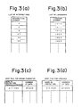
- Figs. 3 (a) and (b) respectively show a list of intersections that are located in each sub-district and a list of landmarks located in each sub-district.
- the lists contain the intersection numbers and landmark numbers, respectively.
- Figs. 3 (c) and (d) respectively show the sort files of Romaji and Hiragana.
- the files contain alphabetically arranged prefecture names and the addresses of data representing the prefectures, and this enables the time required for search of the name of a place to be shortened.
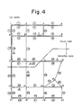
- Fig. 4 shows an example of numbering of roads and intersections on a map.
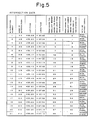
- Fig. 5 shows an example of intersection data.
- the data includes the name of an intersection which corresponds to a intersection number, the coordinate (the latitude and a longitude), the road number which starts from an intersection and which has the smallest number, the road number which ends at that intersection and which has the smallest number, and data representing whether or not an intersection has a signal.
- a route can be searched and various navigation information can be displayed on a display using this data.
- Fig. 6 shows an example of landmark data.
- the data includes the name of a landmark which corresponds to a landmark number, (e.g., the name of a river, the name of a building or the name of a bridge), the coordinate and the intersection numbers located adjacent to a landmark.
- a landmark number e.g., the name of a river, the name of a building or the name of a bridge
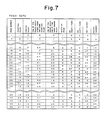
- Fig. 7 shows an example of road data.
- each road has its own number or numbers, and the road data contains the starting point and ending point (the intersection numbers) of each road number, one of the roads which start from the same starting point, one of the roads which end at the same ending point, the width of a road, no-passage data, not guided data (e.g., no data is output when a vehicle proceeds from a road number 1 to a road number 3) and the photo number of an intersection.
- the structure of data stored in the second external storage device e.g., an IC card
- the second external storage device e.g., an IC card
- Fig. 8 shows the intersections and roads which are added to the CD data.
- the roads to be added are indicated by a broken line, and added intersections and roads are affixed with sub-numbers, the road numbers being enclosed by an ellipse.
- intersections from 1-1 through 1-3 and roads from 1-1 through 1-12 are added, and roads 22, 23, 29, 44, 45 and 46 are eliminated from the original map.
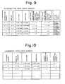
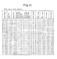
- Figs. 9, 10 and 11 respectively show intersection data, landmark data and road data to be added as the result of the addition of the intersections and roads shown in Fig. 8.
- the data contains the newly added data and data representing the modification of the intersection data and road data caused by the addition.
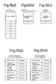
- Fig. 12 (a), (b) and (c) respectively show modified data on the list of sub-districts, the list of intersections and the list of landmarks which are changed as the result of addition of intersections and roads shown in Fig. 8.
- Figs. 13 (a) to (c) respectively show road data, intersection data and landmark data to be deleted.
- Fig. 13 (d) shows the data representing the starting address of the deletion data in the memory
- Fig. 13 (e) shows the data representing the starting address of the modified data in the memory.
- the starting address 0 indicates that the data is not deleted or changed.
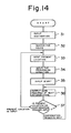
- a driver inputs a destination (in step 31).
- the system is switched into route search mode in which data required to guide a user to the destination is set with respect to all the points other than the destination (in step 32).
- the system switches to present position input mode in which the present position is input (in step 33), and the direction in which the vehicle proceeds from that point is then output (in step 34).
- an intersection confirmation trigger is input (starting of a vehicle is input in step 35), and the data required for the vehicle to reach the destination at a subsequent intersection is then output (in step 36).
- it is monitored which is input next, an intersection confirmation trigger or a present position input button signal (in step 37).
- step 36 If the intersection confirmation trigger is input, the processing returns to step 36. If the signal input is the present position input button signal, the flow returns to step 33.
- a trigger is input every time the intersection is confirmed. If the vehicle passes the intersection where it is to turn and deviates from the course, the present position input button is pressed. Thus, every time the trigger is input, data required for the vehicle to reach the destination at an intersection along the route is output.
- the present position input button is input, the system switches to present position input mode.
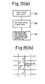
- a destination is set in a work area (in step 39), and the directions in which the vehicle may proceed are set starting from the intersections closest to the destination (in step 40). More specifically, the directions di are set first with respect to the intersections closest to the destination, and the directions d 2 are then set with respect to the second closest intersections, as shown in Fig. 15 (b).
- the route search may also be performed after the step 33 shown in Fig. 14 has been executed. In that case, the route search is performed every time the present position is input. In a trigger input, since the data required for the vehicle to reach the destination is output in accordance with the route set by the route search, the number of intersections that are located on the route is limited. Therefore, the system may also be arranged such that only the data required at these intersections is set.
- step 31 it is first determined as to whether or not the name of a region is input in step 51, as shown in Fig. 16. Subsequently, the list of prefectures, the list of cities and the list of sub-districts are successively searched to fetch the addresses of the intersection list and landmark list using a combination of prefecture, city and sub-district which is input (in steps 52 to 58). If the name of a region is not input, a code number is input in step 60. Thereafter, target intersection setting route is executed in step 59.
- a prefecture, a city and a sub-district may be input through a touch panel or by pressing Romaji or Hiragana keys. A region is selected on the touch panel when that portion of the touch panel is touched.
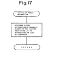
- one of the intersections or landmarks which is the closest to the starting point is searched from the list of intersections and the list of landmarks (route search), as shown in Fig. 17.
- Figs. 16 and 17 are respectively flowcharts of processings generally executed when a route is searched and when the target intersection is searched.
- the data employed in this embodiment consists of CD data stored in the first external storage device 16 and IC card data stored in the second external storage device 17. The processing of these two types of data will be described now with reference to Figs. 18 and 19.
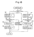
- Fig. 18 is a flowchart of a sub-district search conducted on these two types of data.
- step 61 it is determined in step 61 whether or not there is an IC card. If the answer is negative, the list of sub-districts in the CD [which is shown in Fig. 2 (c)] is searched for the sub-district in step 62, the data on the sub-district is fetched, and a flag indicating that the obtained data is a CD data is set (in steps 63 to 65). If there is an IC card in step 61, the list of sub-districts in the IC card [which is shown in Fig.
- step 12 (a)] is searched for the target sub-district, and it is then determined whether or not there is the sub-district (in steps 67 and 68). If the answer is negative, the processing goes to step 62. On the other hand, if the answer is affirmative, the data on the sub-district is fetched, and a flag indicating that the obtained data is an IC card data is set (in steps 69 and 70).
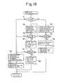
- Fig. 19 is a flowchart of a read of the intersection data. First, it is determined whether or not there is an IC card in step 71. If the answer is negative, the intersection data stored in the CD (shown in Fig. 5) is searched for a necessary intersection and the target intersection data is fetched in step 72. Thereafter, a flag indicating that the obtained data is a CD data is set in step 73. If it is determined that there is an IC card in step 71, the added intersection data stored in the IC card (shown in Fig. 9) is searched for a necessary intersection in step 74. Subsequently, it is determined in step 75 whether or not the necessary intersection data is listed.
- step 76 If the answer is affirmative, the intersection data is fetched, and a flag indicating that the obtained data is an IC card data is then set (in steps 76 and 77). If it is determined that there is no intersection in step 75, the starting address of deletion data stored in the IC card [shown in Fig. 13 (d)] is fetched in step 78. If it is determined that the starting address is 0 (indicating that there is no deletion) in step 79, the processing proceeds to step 72. If the starting address is 0, search is conducted on the deleted intersection file stored in the IC card [shown in Fig. 13 (b)] in step 80. If the file contains the intersection, a flag indicating that the intersection is deleted is then set (in steps 81 and 82).
- Search is conducted on the road data and the landmark data in the same manner as that in which the intersection data is searched. That is, search is conducted first on the data stored in the IC card first and then on the data stored in the CD.
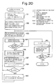
- Fig. 20 is a flowchart of route searching processing which is executed on the basis of the data which is read out from the CD and IC card.
- FF is assigned to the distance L (c) from the starting point with respect to all the intersections, and the search flag F (c) is set at 0 (indicating not searched)(the distance L (c) and search flag F (c) are initialized).
- the distance from the starting point is assigned to the distances of the intersections located adjacent to the starting point, and the flags of the intersections located adjacent to the starting point are set at a search flag 1 (indicating that the intersection is being searched) in step 152. Further, the number of the road that the vehicle has passed after it started from the starting point is set.
- step 153 an intersection whose flag is not 2 (which indicates that the search is over) and which has the smallest distance is found.
- the surrounding road search subroutine is executed. If there is a surrounding road, the optimal route condition setting subroutine is executed (in step 156), and the number of the intersection located at the end of that road and the distance L of the road are input in step 157. Thereafter, in step 158, this distance L is added. If the result is larger than the distance from the starting point, that distance is set as the distance from the starting point, the search flag is set at 1 (indicating that the intersection is being searched), and the number of that road is input (in steps 159 and 160).
- step 154 is executed, and if it is determined that there is no surrounding road in step 155, the search flag is set at 2. Thereafter, the ending condition confirmation subroutine is executed, thereby completing the route search processing (in steps 161 to 163). Thus, the shortest route that is followed from the starting point to the destination is set.
- Fig. 21 is a flowchart of the surrounding road search subroutine which is executed in step 154 in the processing shown in Fig. 20.
- the search of the surrounding road is executed for the first time in step 171. If the answer is affirmative, the numbers of the roads which start from the current intersection are fetched from the intersection data and are stored in step 172.
- the no-passage roads that correspond to the roads that lead to this intersection are fetched from the road data, and it is then determined in step 174 whether or not the roads fetched this time are identical with the no-passage roads explained with reference to Fig. 7. If the answer is no, the fetched roads are stored as the surrounding roads.
- step 171 If it is determined that it is not the first time that the search of the surrounding road is executed in step 171, or if the answer of the step 174 is affirmative, the road having the same starting point as that of the previously searched road and having a subsequent number is fetched from the road data in step 176. Thereafter, in step 177, it is determined whether or not the previously searched road is identical with the road which is fetched this time. If the answer is negative, the processing proceeds to step 173. If the answer is affirmative, the processing goes to step 178 where it is determined that there is no surrounding road.
- Fig. 22 is a flowchart of the optimal route condition setting subroutine executed in step 156 of the processing shown in Fig. 20.
- the width and length of the surrounding road are read in from the road data, and it is then determined whether or not the width is, for example, 1 m or less (in steps 201 and 202). If the width exceeds 1 m, the processing proceeds to step 203. If the width is 1 m or less, it is, for example, doubled in step 203, and the no guided data on the roads that lead to the currently searched intersection is read in from the road data in step 204. Thereafter, it is determined in step 205 whether or not there are surrounding roads that are identical with the no guided data. If there is such a surrounding road, the processing goes to step 207.
- search is directly conducted on the CD data and IC card data, as has been described with reference to Figs. 18 and 19.
- this embodiment prepares a comparison list of the CD data and IC card data.
- Fig. 23 (a) shows the starting address of the memory where the comparison list data is stored
- Fig. 23 (b) a comparison list for sub-districts which contains the order of modified data for each sub-district
- Fig. 23 (c) shows a comparison list for road data.
- An integer in the column of the order of modified data represents the order taken by the data when it is stored in the memory, -1 and 0 in the column indicating that the data is deleted and that the data is not changed, respectively.
- Figs. 24 (a), (b) and (c) respectively show a comparison list for the intersection data, a comparison list for the landmark data, and the starting address of the modified data.
- the above-described comparison list data may be created by operating data within the CPU. In that case, the CD data on all the intersections is read out and the data read outr is compared with the corresponding IC data so as to determine if there is an addition or deletion of the data. The thus-created comparison list is then stored in the RAM or the like.
- Figs. 25 and 26 show the search processings which employ the above-described comparison lists.
- the sub-district is first searched in the sub-district list file in the CD in step 92, and it is then determined whether or not there is an IC card in step 92. If there is no IC card, data on the sub-district [shown in Fig. 2 (c)] is fetched from the CD, and a flag indicating that the obtained data is a CD data is set (in steps 93 to 96). If it is determined that there is an IC card in step 92, it is determined whether or not the sub-district is listed in step 97.
- step 98 the starting address of the list of sub-districts is fetched from the comparison list starting address file in the IC card [shown in Fig. 23 (a)] in step 98. Subsequently, it is determined whether or not the starting address is 0 in step 99. If the starting address is 0 (which means that there is no change), the processing goes to step 95. If the starting address is not 0, the order of the modified data on that sub-district is fetched from the comparison list for sub-districts [shown in Fig. 23 (b)] in step 100. Next, in step 101, it is determined whether or not the order is larger than 0. If the answer is no (which means that there is no change), the processing goes to step 95.
- the stored address of the modified data is obtained and the data on the sub-district [shown in Fig. 12 (a)] is fetched from the IC card in step 102, and a flag indicating that the data is an IC card data is set in step 103. If it is determined in step 97 that the sub-district is not listed, the sub-district modified data [shown in Fig. 12 (a)] is searched for th sub-district. If the sub-district is listed, a flag indicating that the data is an IC card data is set in step 106.
- Fig. 26 is a flowchart of the read of the intersection data.
- step 111 it is determined in step 111 whether or not there is an IC card. If there is no IC card, the intersection data in the IC (shown in Fig. 5) is searched to fetch the necessary intersection data in step 112, and a flag indicating that the data is an CD data is set in step 113. If it is determined in step 111 that there is an IC card, it is determined in step 114 whether or not the intersection is an added one. If it is not an added intersection, the starting address of the list of intersections is fetched from the comparison list data starting address file [shown in Fig. 23 (a)] in the IC card in step 115.
- step 116 it is determined in step 116 whether or not the starting address is 0. If the starting address is 0 (which means that there is no change), the processing goes to step 112. If the starting address is not 0, the order of the modified data on that intersection is obtained from the intersection comparison list file [shown in Fig. 24 (a)] in step 117. Next, it is determined in step 118 whether or not the order is larger than 0. If it is not larger than 0 (which means that there is no change), the processing goes to step 112. If the order is larger than 0, the stored address of the modified data is obtained and the intersection data [shown in Fig.
- step 12 (a)] is fetched from the IC card in step 119, and a flag indicating that the data is an IC card data is then set in step 120.
- step 121 it is determined whether or not the order obtained in step 171 is a negative value. If it is, a flag indicating that the intersection is deleted is set in step 122. If it is determined that the intersection is an added one in step 114, the intersection data in the IC card (shown in Fig. 9) is searched to fetch the intersection data in step 123, and the processing then proceeds to step 120.
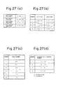
- Fig. 27 (a) shows a method of designating a modified region using the most northerly latitude, the most southerly latitude, the most easterly longitude, and the most westerly longitude
- Fig. 27 (b) shows a method of designating the modified region using a polygon defined by latitude and longitude
- Fig. 27 (c) shows a method of designating a modified region using a polygon defined by roads
- Fig. 27 (d) shows a method of designating a modified region using the intersections or landmarks.
- Fig. 28 is a flowchart of processing of search of intersection data which is employed by this region designation method.
- the intersection data (shown in Fig. 5) is fetched from the CD, and it is then determined in step 212 whether or not there is an IC card. If there is no IC card, a flag indicating that the data is a CD data is set in step 213. If there is an IC card in step 212, it is determined whether or not the intersection is within the modified region designated by any of the methods shown in Fig. 27. If the intersection is outside of the modified region, the processing proceeds to step 213. If it is within the region, the added intersection data (shown in Fig. 9) stored in the IC card is searched for a necessary intersection (in step 216).
- step 217 If it is determined in step 217 that the intersection is listed, the intersection data is fetched from the IC card in step 218, and a flag indicating that the data is an IC card data is then set in step 219. If it is determined in step 217 that the necessary intersection is not included in the added intersection data in the IC card, the starting address of the intersection data is fetched from the deletion list data starting address [shown in Fig. 13 (d)] in step 230. Thereafter, it is determined in step 231 whether or not the starting address is 0. If it is not 0, the deleted intersection list file shown in Fig. 13 (b)] in the IC card is searched. If the intersection is contained in the file, a flag indicating that the intersection is deleted is set (in steps 233 and 234).
- Fig. 29 is a flowchart of road data search processing employed in the region designation method. The contents of the processing are the same as those shown in Fig. 28, description thereof being omitted.
- Fig. 30 (a) is a flowchart of processing of determining whether or not the data is within a region which is executed when the region is designated using the roads shown in Fig. 27 (c).
- the road numbers required to designate a region are read from the IC card, and the data read is assigned to LN(1) ... LN(n) in step 271.
- the starting points and ending points of the roads designated by LN(1) ... LN(n) are read from the CD, and the data read which represent the starting points is assigned to LNS(1) ... LNS (n) while the data representing the ending points is assigned to LNE (1) ... LNE (n) (in step 272).
- the stating points and ending points are compared with each other so as to check whether or not the roads are connected (in steps 273 and 274). If the roads are not connected, a data inputting error flag is set (in step 281).
- step 275 it is determined in step 275 whether or not the starting point of the first road is identical with the ending point of the last road, i.e., whether or not the intersection is surrounded by the roads. If it is not surrounded by the roads, a (n + 1)th road is virtually created so that the intersection can be surrounded by the roads in step 280. Thereafter, in step 276, a point of intersection where each road crosses the latitude line that passes the intersection is calculated, and the number XN of points of intersection located on the right side of the intersection is then counted. Next, it is determined in step 277 whether or not this XN is an odd number, and a flag indicating that the intersection is within the region or outside the region is accordingly set (in step 278 or 279).
- Fig. 30 (b) shows examples in which the intersection is within the region and outside the region.
- a comparison list may be made beforehand by checking if each of the intersections is located outside the region or if it is a modified data, and the resultant comparison list may be stored in the RAM or the like.
- Fig. 31 shows the structure of geographical feature data stored in a CD.
- the geographical data includes the most northerly latitude, the most southerly latitude, the most easterly longitude, the most westerly longitude, adjacent screens G1 to G8, screen data a11 ... a mn , and a plurality of large-and small-scale maps.
- the screen data represents lands, sea, rivers and so on displayed on the screen in different colors using the bit mapping technique.
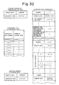
- Fig. 32 shows added geographical feature data stored in an IC card, which includes the comparison list data starting address shown in Fig. 32 (a), the geographical data comparison list shown in Fig. 32 (b), the modified data starting address shown in Fig. 32 (c), and the added geographical data shown in Fig. 32 (d).
- the IC card may also store the map of a parking lot or the like which cannot be stored in the CD. This allows for the reduction in the number of data stored in the CD.
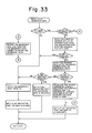
- Fig. 33 is a flowchart of processing of read of the geographical feature data. The contents of the processing are the same as those shown in Fig. 26, description thereof being omitted.
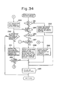
- Fig. 34 is a flowchart of processing of search of the geographical feature data to be displayed.
- step 281 it is determined in step 281 whether or not it is the first time that the search is conducted. If it is, the geographical feature data which has a designated screen size and which contains the present position is searched (in steps 282 and 283). If it is determined that it is not the first time in step 281, it is determined in step 284 whether or not the screen size is to be changed. If the screen size is to be changed, it is determined in step 285 whether or not the screen is enlarged in step 285. If it is determined that the screen is scaled down, small-scale map data of a large area which contains the currently displayed screen is searched in step 286.
- step 287 If it is determined in step 285 that the screen is enlarged, it is determined in step 287 whether or not there are enlarged maps. If there are enlarged maps, the enlarged map of the portion in the area which contains the present position is searched in step 288. If there are no enlarged maps, the fact that there is no enlarged maps is informed to the driver in step 289. If the answer is negative in step 284, the processing goes to step 290 where it is determined whether or not the currently displayed screen contains the present position. If it does not, search is conducted on the latitude/longitude data for the adjacent screen which contains the present position in step 291. Thereafter, it is determined in step 292 whether or not there is the adjacent screen which contains the present position. If there is, the processing goes to step 283. If there is no such adjacent screen, the processing goes to step 286 where the small-scale map data is searched.
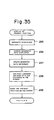
- Fig. 35 is a flowchart of the processing of modification of the geographical feature data. This enables the roads, landmarks and names of places to be added on the screen and enables the present position on the display to be marked.
- the present invention is applied to the coordinate origin method. It is to be noted, however, if the contents of the data are selected, the present invention can be applied to the fixed route method or the location method.
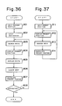
- Fig. 36 is a flowchart of the navigation control conducted in the fixed route method. Once a user has input the present location and a destination, route search is executed (in steps 301 to 303). Once the route has been fixed, the present position and the route are displayed (in steps 304 and 305). Subsequently, the sensor signal which represents the vehicle position is input, and the present position is then calculated (in steps 306 and 307). The processing from steps 303 to 307 is repeated in step 308 to guide the vehicle to the destination.
- Fig. 37 is a flowchart of the navigation control conducted in the location method.
- route search is not executed, and the map and the vehicle position are displayed on a screen.
- only the geographical feature data is stored in a CD and an IC card.
Description
- The present invention relates to a navigation system for outputting information required to reach a destination.
- Recently, navigation systems for vehicles have been developed which are designed to output on a display various types of information required for a driver who is unfamiliar with a particular area to reach a destination and thereby guide the driver to the destination.
- Conventional nagivation systems fall into two types: the location method and fixed route method.
- The location method was proposed in, for example, the specification of Japanese Patent Laid-Open No. 58-115600. In this method, a map stored in an external memory is read out and is stored in an image memory by an arithmetic and logic unit constituted by a microcomputer. Also, the arithmetic and logic unit calculates the locus of a vehicle using data input from azimuth and distance sensors, and displays the map and the locus of the vehicle on a display.
- Japanese Patent Laid-Open No. 62-142216 discloses the fixed route type navigation system. In this method, a course that is to be followed from a starting point to a destination is set beforehand, and the driver is guided in accordance with the course set. The next intersection along the course where the vehicle is to turn is indicated in this method by numerically or graphically displaying the distance remaining before that intersection is reached. So, the driver looks at the course indicated on the map and knows the intersection where he should turn. Altenatively, the driver looks at the numerals or graph displayed to ascertain the distance remaining to that intersection, and thus knows the intersection where the vehicle should be turned.
- In both the location method and the fixed route method, the information required to guide a vehicle to a destination such as map data or intersection data is stored in one external memory such as a floppy disk, a CD-ROM, or a magnetic tape. Guided navigation to a plurality of areas (e.g., to Nagoya and Kyoto) is made possible by using corresponding external memories which are switched with each other as required.
- In both of the above-described conventional navigation systems in which the information required to guide a vehicle to one area, e.g., Kyoto, such as map data or intersection data, is stored in the external memory beforehand, not all the information is stored in the external memory. Also, it is very difficult to store all the information in the external memory, both in terms of storage capacity and the calculation ability of the central processing unit. Even if all the necessary information is input in the memory, a large amount of information makes selection of a destination very difficult. In both of these navigation systems, it is impossible to guide a vehicle if the memory does not contain the information on a desired starting point or destination beforehand. In that case, a driver has to go to a nearby starting point which is stored in the memory without the assistance of the navigation system. He also has to go to his true destination by himself after he has reached the destination input in the memory beforehand.
- Further, modification, addition and deletion of the information stored in an external memory such as map data or intersection data requires a great deal of time and expense.
- The above-described location method has its own problem in that, in a case where it is necessary to turn at an intersection indicated on a map displayed on the display device, it may be impossible for a driver to indentify an intersection where the vehicle is approaching with the one indicated on the map, due to errors accumulated in the measured running distance or direction. The driver may pass an intersection where he should turn, or the present position on the map may not correspond with a road on the map.
- In the fixed route method, since the course to be followed from a starting point to a destination is set beforehand and the vehicle is guided in accordance with the course set, it is difficult to change the destination during travel. Further, if, for example, a wrong turning is made and the driver deviates from the original course, it is impossible to continue travelling under the guidance of the navigation system unless the vehicle can be returned to the course originally set. Furthermore, it is necessary to judge whether a vehicle has passed a predetermined intersection as planned on the basis of running distance data prepared by a distance sensor or data representing right or left turns which is obtained through a steering sensor. In consequence, any detection errors which occur during actual travel may cause misjudgement.
- In order to obviate these problems, the present inventors filed an application in respect of a navigation system for outputting information required to guide a vehicle to a destination at a plurality of points (in Japan under Japanese Patent Application No. 62-307805 and in the U.S.A. on October 20, 1988). In this system, the coordinates of a plurality of points are set and the information required to reach the destination is calculated at each of these points. This method (hereinafter referred to as the coordinate origin method) has the advantage that it is possible to change a destination during travel and that the course followed to a destination can be searched relative to any of the plural points. However, as stated above, it is difficult to input all the information required to guide a vehicle to a particular destination. It is therefore essential to decide properly which information is to be stored and how the stored information is to be used.
- It would therefore be desirable to provide a navigation system which can obviate the aforementioned problems, which enables a vehicle to be guided to a destination from any starting point by preparing a standard data base as an internal or external memory and an individual data base that complements this standard data base as an external memory, and which enables the data to be updated relatively easily.
- There is known, for example from PATENT ABSTRACTS OF JAPAN, vol. 11, no. 334, (P-631) [2781 31.10.87; & JP-A-62116210 a navigation system for a vehicle comprising: a first external storage means for storing first guidance data including road and intersection data; a second storage means for storing second guidance data; said guidance data being linked to said first guidance data; output means for outputting guidance information; and CPU means for receiving said first and second guidance data from said first and second storage means, supplementing said first guidance data by said second guidance data, and outputting said guidance information based on said supplemented guidance data via said output means. In this arrangement the first external storage means stores map information and the second storage means which is in the form of a floppy disc may store additional information to be displayed together with the map information. Such additional information may for example he picture cage information and the positional adjustment of the information to be displayed from the two storage means must be effected manually. Thus, such an arrangement cannot provide for automatic updating of redundant map information that may exist in the first storage means by replacement map information that may overlap with the redundant information to be replaced.
- Other means for providing information to be displayed from more than once source are known for example from PATENT ABSTRACTS OF JAPAN, vol. 12, no. 185, (P-710) [3032], 31.05.88; and JP-A-62293120; PATENT ABSTRACTS OF JAPAN, vol. 11, no. 366, (P-641)[2813], 28.11.87; JP-A-62138719, and DE-A-3323704.
- It is an object of the present invention to provide an improved navigation system of the kind set out above, wherein overlapping map data from two sources can be coordinated automatically to overcome the problems already outlined above.
- This object is achieved by the features of the characterising clause of
Claim 1. - In one example of the present invention, the first external storage device, which may be a CD, stores data representing the standard map of an area and the data required for guiding a vehicle in that area, and the second external storage device, which may be an IC card, stores individual data which cannot be complemented by the standard map data and the guidance data. In an actual operation, the CD stores the data representing the major route map of Japan or any area in the world and the data required for guidance. The IC card stores the data on the map of the vicinity of a hotel, a gas station or a rental car office in a particular area, and the data needed to guide a vehicle in that vicinity. IC cards are prepared for various objectives. For example, IC cards which store data needed to guide a user on a sightseeing trip or that needed to guide a user to commercial premises, a station or an airport may be prepared. Th IC cards may additionally store traffic information or weather information. The hotels, gas stations and rental car offices may serve as information centers where data is input into the card and data in the card is updated, and where these cards are sold and supplied to users. Thus, a user is first led to a target area using a CD. After arriving the area, he receives an IC card at the information center, and is then guided to a target location with the assistance of that card. Alternatively, data which is prepared in an information center may be input to the RAM of the CPU or to the IC card by a communication device such as a car telephone through a telephone line. In that case, it is not necessary to prepare CD or IC cards which store data beforehand.
- Thus, in the present invention, since only the detailed data which is adequate for a desired area and a desired objective can be stored in the IC card which serves as the second external storage device, the data stored in the first external storage device which is a CD can be simplified. Further, modification and addition of data is performed on that stored in the IC card, and this facilitates maintenance operation. Furthermore, since data is stored in both CD and IC card, the number of data stored can be reduced. This makes the operation simpler and enables a data that meets the demand of a user to be selectively supplied to the user. As a result, guided navigation is made possible from any starting point to a destination by preparing a standard data base and an individual data base that complements the standard data base as the external memories. Further, data updating can be made relatively easy.
-
- Fig. 1 (a) is a block diagram of a navigation system, showing a first embodiment of the present invention;
- Fig. 1 (b) shows the structure of an external storage device;
- Figs. 2, 3, 4, 5, 6 and 7 show the structure of data stored in the first external storage device;
- Figs. 8, 9, 10, 11, 12 and 13 show the structure of data stored in the second external storage device;
- Fig 14 is a flowchart of the control processing executed in the coordinate origin method;
- Fig. 15 is a flowchart of route searching processing;
- Fig. 16 is a flowchart of destination inputting process;
- Fig. 17 is a flowchart of destination setting process;
- Figs. 18 and 19 are flowcharts of a data searching process executed in the first embodiment of the present invention;
- Figs. 20, 21, and 22 are flowcharts of route searching process;
- Figs. 23 and 24 show the structure of data, showing a second embodiment of the present invention;
- Figs. 25 and 26 are flowcharts of a data searching process executed in the second embodiment of the present invention;
- Fig. 27 shows the structure of data, showing a third embodiment of the present invention;
- Figs. 28, 29 and 30 (a) are flowcharts of a data searching process executed in the third embodiment of the present invention;
- Fig. 30 (b) explains a method of judging whether a data is within an area or outside of the area;
- Figs. 31 and 32 show the structure of data, showing a fourth embodiment of the present invention;
- Figs. 33, 34 and 35 are flowcharts of a data searching process executed in the fourth embodiment of the present invention; and
- Figs. 36 and 37 are flowcharts, showing another types of navigation system to which the present invention is applied.
- Embodiments of the present invention will be described below with reference to the accompanying drawings.
- Referring first to Fig. 1 which is a block diagram of a first embodiment of a navigation system according to the present invention, a system comprises a man-
machine interface 1, a presentposition checking unit 2, anexternal storage unit 3, and acentral processing unit 4. - The man-
machine interface 1 includes at least adisplay device 5 and aninputting device 6. Thedisplay device 5 may comprise a CRT, a liquid crystal display or the like. Theinputting device 6 may comprise a keyboard, a touch-panel, a light pen, a mouse or the like. The man-machine interface 1 optically includes aspeech output device 7 such as a speaker and acommunication device 9 such as a car telephone. - The present
position checking unit 2 employs either areceiver 10 for a global positioning system (GPS) which measures a position utilizing an artificial satellite, abeacon receiver 11 for receiving the positional information from a beacon disposed on a road, ageomagnetic sensor 12, adistance sensor 13 or asteering sensor 15. Both of theGPS receiver 10 and thebeacon receiver 11 can be used as a single unit to measure the present position. However, thegeomagnetic sensor 12 and thesteering sensor 15 must be used together with thedistance sensor 13. - The
external storage unit 3 consists of a firstexternal storage device 16 and a secondexternal storage device 17. Floppy disks, CD-ROMs, optical disks, magnetic tapes, IC cards, or optical cards may be used as the first andsecond storage devices external storage device 16, and the secondexternal storage device 17 may be of the card type which can be manufactured at a low cost. The firstexternal storage device 16 which may be a CD stores data on the standard map of a particular area and the data required to guide a vehicle in that area, and the secondexternal storage device 17 which may be an IC card stores individual data which cannot be complemented by the data on the standard map and that required for guidance. More specifically, as shown in Fig. 1 (b), data on the major route map of Japan or of any area in the world, as well as the data required for guidance are input in the CD, and data on the map of the vicinity of a hotel, a gas station or a rental car office located in a certain area and data required for guidance are input in the IC card. IC cards may be prepared for various objectives, e.g., IC cards storing information required to guide a user on a sightseeing trip or that required to guide a user to commercial premises, a station or an airport may be prepared. IC cards may additionally store traffic information, weather information and the like. The hotels, gas stations and rental car offices may serve as information centers where data is input or data in the IC card is updated, and where IC cards are sold or supplied to users. Thus, a user is first led to a target area using a CD. After arriving at that area, he receives an IC card at the information center and is then led to a destination with the assistance of that IC card. It is to be noted, however, that the data representing the map and that required for guidance are structured in different ways in the location method, the fixed route method and the coordinate origin method, as will be described later. - This embodiment employs two
external storage devices CPU 4 rather than in the firstexternal storage device 16. - Once a user has input a destination through the
inputting unit 1, theCPU 4 reads out the data representing a map and that required for guidance from theexternal storage unit 3, operates the data, stores the operation results in aRAM 20, and outputs the necessary results to thedisplay device 5 or thespeech output device 6 in accordance with a navigation program stored in aROM 19. The data required to guide a user which is output from theexternal storage unit 3 represents the data required for the vehicle to reach the destination. To a vehicle which is located at an intersection on a specific route, data representing a right turn or a left turn that the vehicle should make at a subsequent intersection is output. In a case where there is another intersection very close to a first intersection where the vehicle turns, the data representing the direction in which the vehicle should turn at the first intersection and that representing a traffic lane in which the vehicle should travel after it has turned at the first intersection may be output as information required for guidance. Alternatively, the direction in which the vehicle should turn at the second intersection may also be output as information required for guidance. - In addition, the data which is prepared in an
information center 21 may be input by thecommunication device 9 such as a car telephone through a telephone line, the input data being entered to the RAM of theCPU 4 or in an IC card through amodem 22. In this case, it is not necessary to store data in an IC card beforehand. A hotel, a gas station or a rental car office in an area may be able to serve as theinformation center 21. Alternatively, an information center which acts as a service center for the entire region or a metropolitan area may be installed. - Next, the structure of the data employed in the navigation system for the vehicle according to the present invention, as well as the control process executed in the navigation system will be described below.
- First, an example in which the present invention is applied to the coordinate origin method will be described.
- Figs. 2 to 7 show the structure of the data stored in the first external storage device (e.g., in a CD) employed in the navigation system for the vehicle according to the present invention.
- Fig. 2 (a) shows a list of relatively broad regions, e.g., a list of prefectures.
Prefecture number 01 represents Aichi Prefecture. The list contains prefecture names in Chinese character, Hiragana and Romaji, the address of list of cities (the starting address thereof), the number of cities listed, the major intersections/landmarks numbers and so on. Fig. 2 (b) shows a list of wards or cities which is the data narrower than the region data. The list contains city names in Chinese character, Hiragana and Romaji, the address of list of sub-districts (the starting address thereof), the number of sub-districts listed, the major intersections/landmarks numbers and so on. Fig. 2 (c) shows a list of sub-districts, which is the data narrower than the ward or city data. The list contains sub-district names in Chinese character, Hiragana and Romaji, the address of list of intersections (the starting address thereof), the number of intersections listed, the address of list of landmarks, the number of landmarks listed, the major intersections/landmarks numbers and so on. Such hierarchically structured data enables the list of prefectures, the list of cities and the list of sub-districts to be searched for a starting point, a present position or a destination input in that order. Further, it enables the major intersection or landmark to be separately searched in the list of prefectures, in the list of cities and in the list of sub-districts. - Figs. 3 (a) and (b) respectively show a list of intersections that are located in each sub-district and a list of landmarks located in each sub-district. The lists contain the intersection numbers and landmark numbers, respectively. Figs. 3 (c) and (d) respectively show the sort files of Romaji and Hiragana. The files contain alphabetically arranged prefecture names and the addresses of data representing the prefectures, and this enables the time required for search of the name of a place to be shortened.
- Fig. 4 shows an example of numbering of roads and intersections on a map. In two sub-districts, there are 21 intersections from 1 to 21, and there are 46 roads from 1 to 46. If two-way traffic is allowed on a road, two different numbers are affixed to that road. If the road is a one-way road, one number is affixed to that road.
- Fig. 5 shows an example of intersection data. The data includes the name of an intersection which corresponds to a intersection number, the coordinate (the latitude and a longitude), the road number which starts from an intersection and which has the smallest number, the road number which ends at that intersection and which has the smallest number, and data representing whether or not an intersection has a signal. A route can be searched and various navigation information can be displayed on a display using this data.
- Fig. 6 shows an example of landmark data. The data includes the name of a landmark which corresponds to a landmark number, (e.g., the name of a river, the name of a building or the name of a bridge), the coordinate and the intersection numbers located adjacent to a landmark.
- Fig. 7 shows an example of road data. As shown in Fig. 4, each road has its own number or numbers, and the road data contains the starting point and ending point (the intersection numbers) of each road number, one of the roads which start from the same starting point, one of the roads which end at the same ending point, the width of a road, no-passage data, not guided data (e.g., no data is output when a vehicle proceeds from a
road number 1 to a road number 3) and the photo number of an intersection. - Next, the structure of data stored in the second external storage device (e.g., an IC card) will be described below with reference to Figs. 8 to 13.
- Fig. 8 shows the intersections and roads which are added to the CD data. The roads to be added are indicated by a broken line, and added intersections and roads are affixed with sub-numbers, the road numbers being enclosed by an ellipse. As shown in Fig. 8, intersections from 1-1 through 1-3 and roads from 1-1 through 1-12 are added, and
roads - Figs. 9, 10 and 11 respectively show intersection data, landmark data and road data to be added as the result of the addition of the intersections and roads shown in Fig. 8. The data contains the newly added data and data representing the modification of the intersection data and road data caused by the addition.
- Fig. 12 (a), (b) and (c) respectively show modified data on the list of sub-districts, the list of intersections and the list of landmarks which are changed as the result of addition of intersections and roads shown in Fig. 8.
- Figs. 13 (a) to (c) respectively show road data, intersection data and landmark data to be deleted. Fig. 13 (d) shows the data representing the starting address of the deletion data in the memory, and Fig. 13 (e) shows the data representing the starting address of the modified data in the memory. The starting
address 0 indicates that the data is not deleted or changed. - Control of the thus-arranged navigation system which employs the coordinate origin method will be described below with reference to Figs. 14 to 22.
- Referring first to Fig. 14, a driver inputs a destination (in step 31). Once the destination has been input, the system is switched into route search mode in which data required to guide a user to the destination is set with respect to all the points other than the destination (in step 32). After the route has been searched, the system switches to present position input mode in which the present position is input (in step 33), and the direction in which the vehicle proceeds from that point is then output (in step 34). Thereafter, an intersection confirmation trigger is input (starting of a vehicle is input in step 35), and the data required for the vehicle to reach the destination at a subsequent intersection is then output (in step 36). Next, it is monitored which is input next, an intersection confirmation trigger or a present position input button signal (in step 37). If the intersection confirmation trigger is input, the processing returns to step 36. If the signal input is the present position input button signal, the flow returns to step 33. In other words, in this system, when the vehicle is running as guided, a trigger is input every time the intersection is confirmed. If the vehicle passes the intersection where it is to turn and deviates from the course, the present position input button is pressed. Thus, every time the trigger is input, data required for the vehicle to reach the destination at an intersection along the route is output. When the present position input button is input, the system switches to present position input mode.
- As shown in Fig. 15 (a), Once the system has been switched to route search mode, a destination is set in a work area (in step 39), and the directions in which the vehicle may proceed are set starting from the intersections closest to the destination (in step 40). More specifically, the directions di are set first with respect to the intersections closest to the destination, and the directions d2 are then set with respect to the second closest intersections, as shown in Fig. 15 (b). The route search may also be performed after the
step 33 shown in Fig. 14 has been executed. In that case, the route search is performed every time the present position is input. In a trigger input, since the data required for the vehicle to reach the destination is output in accordance with the route set by the route search, the number of intersections that are located on the route is limited. Therefore, the system may also be arranged such that only the data required at these intersections is set. - Once a destination has been input in
step 31, it is first determined as to whether or not the name of a region is input instep 51, as shown in Fig. 16. Subsequently, the list of prefectures, the list of cities and the list of sub-districts are successively searched to fetch the addresses of the intersection list and landmark list using a combination of prefecture, city and sub-district which is input (insteps 52 to 58). If the name of a region is not input, a code number is input instep 60. Thereafter, target intersection setting route is executed instep 59. A prefecture, a city and a sub-district may be input through a touch panel or by pressing Romaji or Hiragana keys. A region is selected on the touch panel when that portion of the touch panel is touched. - In the target intersection setting subroutine executed in
step 59 in Fig. 16, one of the intersections or landmarks which is the closest to the starting point is searched from the list of intersections and the list of landmarks (route search), as shown in Fig. 17. - Figs. 16 and 17 are respectively flowcharts of processings generally executed when a route is searched and when the target intersection is searched. However, the data employed in this embodiment consists of CD data stored in the first
external storage device 16 and IC card data stored in the secondexternal storage device 17. The processing of these two types of data will be described now with reference to Figs. 18 and 19. - Fig. 18 is a flowchart of a sub-district search conducted on these two types of data. First, it is determined in
step 61 whether or not there is an IC card. If the answer is negative, the list of sub-districts in the CD [which is shown in Fig. 2 (c)] is searched for the sub-district instep 62, the data on the sub-district is fetched, and a flag indicating that the obtained data is a CD data is set (insteps 63 to 65). If there is an IC card instep 61, the list of sub-districts in the IC card [which is shown in Fig. 12 (a)] is searched for the target sub-district, and it is then determined whether or not there is the sub-district (insteps 67 and 68). If the answer is negative, the processing goes to step 62. On the other hand, if the answer is affirmative, the data on the sub-district is fetched, and a flag indicating that the obtained data is an IC card data is set (insteps 69 and 70). - Fig. 19 is a flowchart of a read of the intersection data. First, it is determined whether or not there is an IC card in
step 71. If the answer is negative, the intersection data stored in the CD (shown in Fig. 5) is searched for a necessary intersection and the target intersection data is fetched instep 72. Thereafter, a flag indicating that the obtained data is a CD data is set instep 73. If it is determined that there is an IC card instep 71, the added intersection data stored in the IC card (shown in Fig. 9) is searched for a necessary intersection instep 74. Subsequently, it is determined instep 75 whether or not the necessary intersection data is listed. If the answer is affirmative, the intersection data is fetched, and a flag indicating that the obtained data is an IC card data is then set (insteps 76 and 77). If it is determined that there is no intersection instep 75, the starting address of deletion data stored in the IC card [shown in Fig. 13 (d)] is fetched instep 78. If it is determined that the starting address is 0 (indicating that there is no deletion) instep 79, the processing proceeds to step 72. If the starting address is 0, search is conducted on the deleted intersection file stored in the IC card [shown in Fig. 13 (b)] instep 80. If the file contains the intersection, a flag indicating that the intersection is deleted is then set (insteps 81 and 82). - Search is conducted on the road data and the landmark data in the same manner as that in which the intersection data is searched. That is, search is conducted first on the data stored in the IC card first and then on the data stored in the CD.
- Fig. 20 is a flowchart of route searching processing which is executed on the basis of the data which is read out from the CD and IC card. First, in
step 151, FF is assigned to the distance L (c) from the starting point with respect to all the intersections, and the search flag F (c) is set at 0 (indicating not searched)(the distance L (c) and search flag F (c) are initialized). Next, the distance from the starting point is assigned to the distances of the intersections located adjacent to the starting point, and the flags of the intersections located adjacent to the starting point are set at a search flag 1 (indicating that the intersection is being searched) instep 152. Further, the number of the road that the vehicle has passed after it started from the starting point is set. Instep 153, an intersection whose flag is not 2 (which indicates that the search is over) and which has the smallest distance is found. Subsequently, insteps step 157. Thereafter, instep 158, this distance L is added. If the result is larger than the distance from the starting point, that distance is set as the distance from the starting point, the search flag is set at 1 (indicating that the intersection is being searched), and the number of that road is input (insteps 159 and 160). Next, thestep 154 is executed, and if it is determined that there is no surrounding road instep 155, the search flag is set at 2. Thereafter, the ending condition confirmation subroutine is executed, thereby completing the route search processing (insteps 161 to 163). Thus, the shortest route that is followed from the starting point to the destination is set. - Fig. 21 is a flowchart of the surrounding road search subroutine which is executed in
step 154 in the processing shown in Fig. 20. First, it is determined whether or not the search of the surrounding road is executed for the first time instep 171. If the answer is affirmative, the numbers of the roads which start from the current intersection are fetched from the intersection data and are stored instep 172. Next, instep 173, the no-passage roads that correspond to the roads that lead to this intersection are fetched from the road data, and it is then determined instep 174 whether or not the roads fetched this time are identical with the no-passage roads explained with reference to Fig. 7. If the answer is no, the fetched roads are stored as the surrounding roads. If it is determined that it is not the first time that the search of the surrounding road is executed instep 171, or if the answer of thestep 174 is affirmative, the road having the same starting point as that of the previously searched road and having a subsequent number is fetched from the road data instep 176. Thereafter, instep 177, it is determined whether or not the previously searched road is identical with the road which is fetched this time. If the answer is negative, the processing proceeds to step 173. If the answer is affirmative, the processing goes to step 178 where it is determined that there is no surrounding road. - Fig. 22 is a flowchart of the optimal route condition setting subroutine executed in
step 156 of the processing shown in Fig. 20. First, the width and length of the surrounding road are read in from the road data, and it is then determined whether or not the width is, for example, 1 m or less (insteps 201 and 202). If the width exceeds 1 m, the processing proceeds to step 203. If the width is 1 m or less, it is, for example, doubled instep 203, and the no guided data on the roads that lead to the currently searched intersection is read in from the road data instep 204. Thereafter, it is determined instep 205 whether or not there are surrounding roads that are identical with the no guided data. If there is such a surrounding road, the processing goes to step 207. If there is no such a surrounding road, 100 m, for example, is added to the length of the road, and the result is then added to the virtual distance of the currently searched intersection from the starting point to obtain the virtual distance of the intersection located at the end of the surrounding road instep 207. - Next, another embodiment of the present invention will be described below with reference to Figs. 23 to 26. In the first embodiment, search is directly conducted on the CD data and IC card data, as has been described with reference to Figs. 18 and 19. On the other hand, this embodiment prepares a comparison list of the CD data and IC card data.
- Fig. 23 (a) shows the starting address of the memory where the comparison list data is stored, Fig. 23 (b) a comparison list for sub-districts which contains the order of modified data for each sub-district, and Fig. 23 (c) shows a comparison list for road data. An integer in the column of the order of modified data represents the order taken by the data when it is stored in the memory, -1 and 0 in the column indicating that the data is deleted and that the data is not changed, respectively. Figs. 24 (a), (b) and (c) respectively show a comparison list for the intersection data, a comparison list for the landmark data, and the starting address of the modified data.
- The above-described comparison list data may be created by operating data within the CPU. In that case, the CD data on all the intersections is read out and the data read outr is compared with the corresponding IC data so as to determine if there is an addition or deletion of the data. The thus-created comparison list is then stored in the RAM or the like.
- Figs. 25 and 26 show the search processings which employ the above-described comparison lists.
- In the sub-district search processing shown in Fig. 25, the sub-district is first searched in the sub-district list file in the CD in
step 92, and it is then determined whether or not there is an IC card instep 92. If there is no IC card, data on the sub-district [shown in Fig. 2 (c)] is fetched from the CD, and a flag indicating that the obtained data is a CD data is set (insteps 93 to 96). If it is determined that there is an IC card instep 92, it is determined whether or not the sub-district is listed instep 97. If the sub-district is listed, the starting address of the list of sub-districts is fetched from the comparison list starting address file in the IC card [shown in Fig. 23 (a)] instep 98. Subsequently, it is determined whether or not the starting address is 0 instep 99. If the starting address is 0 (which means that there is no change), the processing goes to step 95. If the starting address is not 0, the order of the modified data on that sub-district is fetched from the comparison list for sub-districts [shown in Fig. 23 (b)] instep 100. Next, instep 101, it is determined whether or not the order is larger than 0. If the answer is no (which means that there is no change), the processing goes to step 95. If the answer is yes, the stored address of the modified data is obtained and the data on the sub-district [shown in Fig. 12 (a)] is fetched from the IC card instep 102, and a flag indicating that the data is an IC card data is set instep 103. If it is determined instep 97 that the sub-district is not listed, the sub-district modified data [shown in Fig. 12 (a)] is searched for th sub-district. If the sub-district is listed, a flag indicating that the data is an IC card data is set instep 106. - Fig. 26 is a flowchart of the read of the intersection data. First, it is determined in
step 111 whether or not there is an IC card. If there is no IC card, the intersection data in the IC (shown in Fig. 5) is searched to fetch the necessary intersection data instep 112, and a flag indicating that the data is an CD data is set instep 113. If it is determined instep 111 that there is an IC card, it is determined instep 114 whether or not the intersection is an added one. If it is not an added intersection, the starting address of the list of intersections is fetched from the comparison list data starting address file [shown in Fig. 23 (a)] in the IC card instep 115. Subsequently, it is determined instep 116 whether or not the starting address is 0. If the starting address is 0 (which means that there is no change), the processing goes to step 112. If the starting address is not 0, the order of the modified data on that intersection is obtained from the intersection comparison list file [shown in Fig. 24 (a)] instep 117. Next, it is determined instep 118 whether or not the order is larger than 0. If it is not larger than 0 (which means that there is no change), the processing goes to step 112. If the order is larger than 0, the stored address of the modified data is obtained and the intersection data [shown in Fig. 12 (a)] is fetched from the IC card instep 119, and a flag indicating that the data is an IC card data is then set instep 120. Instep 121, it is determined whether or not the order obtained instep 171 is a negative value. If it is, a flag indicating that the intersection is deleted is set instep 122. If it is determined that the intersection is an added one instep 114, the intersection data in the IC card (shown in Fig. 9) is searched to fetch the intersection data in step 123, and the processing then proceeds to step 120. - Still another embodiment of the present invention will be described below with reference to Figs. 27 to 30. Whereas the modified data stored in an IC card is searched directly or by using a comparison list in the above-described embodiments, the present embodiment involves designation of a region where the modified data exists.
- Fig. 27 (a) shows a method of designating a modified region using the most northerly latitude, the most southerly latitude, the most easterly longitude, and the most westerly longitude, Fig. 27 (b) shows a method of designating the modified region using a polygon defined by latitude and longitude, Fig. 27 (c) shows a method of designating a modified region using a polygon defined by roads, and Fig. 27 (d) shows a method of designating a modified region using the intersections or landmarks.
- Fig. 28 is a flowchart of processing of search of intersection data which is employed by this region designation method. In
step 211, the intersection data (shown in Fig. 5) is fetched from the CD, and it is then determined instep 212 whether or not there is an IC card. If there is no IC card, a flag indicating that the data is a CD data is set in step 213. If there is an IC card instep 212, it is determined whether or not the intersection is within the modified region designated by any of the methods shown in Fig. 27. If the intersection is outside of the modified region, the processing proceeds to step 213. If it is within the region, the added intersection data (shown in Fig. 9) stored in the IC card is searched for a necessary intersection (in step 216). If it is determined instep 217 that the intersection is listed, the intersection data is fetched from the IC card instep 218, and a flag indicating that the data is an IC card data is then set instep 219. If it is determined instep 217 that the necessary intersection is not included in the added intersection data in the IC card, the starting address of the intersection data is fetched from the deletion list data starting address [shown in Fig. 13 (d)] instep 230. Thereafter, it is determined instep 231 whether or not the starting address is 0. If it is not 0, the deleted intersection list file shown in Fig. 13 (b)] in the IC card is searched. If the intersection is contained in the file, a flag indicating that the intersection is deleted is set (insteps 233 and 234). - Fig. 29 is a flowchart of road data search processing employed in the region designation method. The contents of the processing are the same as those shown in Fig. 28, description thereof being omitted.
- Fig. 30 (a) is a flowchart of processing of determining whether or not the data is within a region which is executed when the region is designated using the roads shown in Fig. 27 (c).
- First, the road numbers required to designate a region are read from the IC card, and the data read is assigned to LN(1) ... LN(n) in
step 271. Next, the starting points and ending points of the roads designated by LN(1) ... LN(n) are read from the CD, and the data read which represent the starting points is assigned to LNS(1) ... LNS (n) while the data representing the ending points is assigned to LNE (1) ... LNE (n) (in step 272). Subsequently, the stating points and ending points are compared with each other so as to check whether or not the roads are connected (insteps 273 and 274). If the roads are not connected, a data inputting error flag is set (in step 281). If the roads are connected, it is determined instep 275 whether or not the starting point of the first road is identical with the ending point of the last road, i.e., whether or not the intersection is surrounded by the roads. If it is not surrounded by the roads, a (n + 1)th road is virtually created so that the intersection can be surrounded by the roads instep 280. Thereafter, instep 276, a point of intersection where each road crosses the latitude line that passes the intersection is calculated, and the number XN of points of intersection located on the right side of the intersection is then counted. Next, it is determined instep 277 whether or not this XN is an odd number, and a flag indicating that the intersection is within the region or outside the region is accordingly set (instep 278 or 279). Fig. 30 (b) shows examples in which the intersection is within the region and outside the region. - As in the case of the method which utilizes a comparison list and which is described with reference to Figs. 25 and 26, a comparison list may be made beforehand by checking if each of the intersections is located outside the region or if it is a modified data, and the resultant comparison list may be stored in the RAM or the like.
- Still another embodiment of the present invention will be described below with reference to Figs. 31 to 35. Whereas each of the above-described embodiments involves storage of modified names of places, intersections and roads in an IC card, modified geographical feature data is stored in an IC card in this embodiment.
- Fig. 31 shows the structure of geographical feature data stored in a CD. The geographical data includes the most northerly latitude, the most southerly latitude, the most easterly longitude, the most westerly longitude, adjacent screens G1 to G8, screen data a11 ... amn, and a plurality of large-and small-scale maps. The screen data represents lands, sea, rivers and so on displayed on the screen in different colors using the bit mapping technique.
- Fig. 32 shows added geographical feature data stored in an IC card, which includes the comparison list data starting address shown in Fig. 32 (a), the geographical data comparison list shown in Fig. 32 (b), the modified data starting address shown in Fig. 32 (c), and the added geographical data shown in Fig. 32 (d). The IC card may also store the map of a parking lot or the like which cannot be stored in the CD. This allows for the reduction in the number of data stored in the CD.
- Fig. 33 is a flowchart of processing of read of the geographical feature data. The contents of the processing are the same as those shown in Fig. 26, description thereof being omitted.
- Fig. 34 is a flowchart of processing of search of the geographical feature data to be displayed. First, it is determined in
step 281 whether or not it is the first time that the search is conducted. If it is, the geographical feature data which has a designated screen size and which contains the present position is searched (insteps 282 and 283). If it is determined that it is not the first time instep 281, it is determined instep 284 whether or not the screen size is to be changed. If the screen size is to be changed, it is determined instep 285 whether or not the screen is enlarged instep 285. If it is determined that the screen is scaled down, small-scale map data of a large area which contains the currently displayed screen is searched instep 286. If it is determined instep 285 that the screen is enlarged, it is determined instep 287 whether or not there are enlarged maps. If there are enlarged maps, the enlarged map of the portion in the area which contains the present position is searched instep 288. If there are no enlarged maps, the fact that there is no enlarged maps is informed to the driver instep 289. If the answer is negative instep 284, the processing goes to step 290 where it is determined whether or not the currently displayed screen contains the present position. If it does not, search is conducted on the latitude/longitude data for the adjacent screen which contains the present position instep 291. Thereafter, it is determined instep 292 whether or not there is the adjacent screen which contains the present position. If there is, the processing goes to step 283. If there is no such adjacent screen, the processing goes to step 286 where the small-scale map data is searched. - Fig. 35 is a flowchart of the processing of modification of the geographical feature data. This enables the roads, landmarks and names of places to be added on the screen and enables the present position on the display to be marked.
- In the above-described embodiments, the present invention is applied to the coordinate origin method. It is to be noted, however, if the contents of the data are selected, the present invention can be applied to the fixed route method or the location method.
- Fig. 36 is a flowchart of the navigation control conducted in the fixed route method. Once a user has input the present location and a destination, route search is executed (in steps 301 to 303). Once the route has been fixed, the present position and the route are displayed (in steps 304 and 305). Subsequently, the sensor signal which represents the vehicle position is input, and the present position is then calculated (in steps 306 and 307). The processing from steps 303 to 307 is repeated in step 308 to guide the vehicle to the destination.
- Fig. 37 is a flowchart of the navigation control conducted in the location method. In this method, route search is not executed, and the map and the vehicle position are displayed on a screen. In consequence, only the geographical feature data is stored in a CD and an IC card.
Claims (16)
Applications Claiming Priority (3)
| Application Number | Priority Date | Filing Date | Title |
|---|---|---|---|
| JP63049965A JP2659742B2 (en) | 1988-03-02 | 1988-03-02 | Navigation device |
| JP4996588 | 1988-03-02 | ||
| JP49965/88 | 1988-03-02 |
Publications (4)
| Publication Number | Publication Date |
|---|---|
| EP0330787A2 EP0330787A2 (en) | 1989-09-06 |
| EP0330787A3 EP0330787A3 (en) | 1991-09-25 |
| EP0330787B1 true EP0330787B1 (en) | 1995-12-13 |
| EP0330787B2 EP0330787B2 (en) | 1999-08-18 |
Family
ID=12845736
Family Applications (1)
| Application Number | Title | Priority Date | Filing Date |
|---|---|---|---|
| EP88312450A Expired - Lifetime EP0330787B2 (en) | 1988-03-02 | 1988-12-30 | Navigation system |
Country Status (4)
| Country | Link |
|---|---|
| US (1) | US4954959A (en) |
| EP (1) | EP0330787B2 (en) |
| JP (1) | JP2659742B2 (en) |
| DE (1) | DE3854785T3 (en) |
Cited By (2)
| Publication number | Priority date | Publication date | Assignee | Title |
|---|---|---|---|---|
| US7668931B2 (en) | 2000-12-22 | 2010-02-23 | Microsoft Corporation | Context-aware systems and methods, location-aware systems and methods, context-aware vehicles and methods of operating the same, and location-aware vehicles and methods of operating the same |
| US8117547B2 (en) | 2000-12-22 | 2012-02-14 | Microsoft Corporation | Environment-interactive context-aware devices and methods |
Families Citing this family (119)
| Publication number | Priority date | Publication date | Assignee | Title |
|---|---|---|---|---|
| US5422812A (en) * | 1985-05-30 | 1995-06-06 | Robert Bosch Gmbh | Enroute vehicle guidance system with heads up display |
| JPH0792388B2 (en) * | 1989-04-17 | 1995-10-09 | 住友電気工業株式会社 | Position detector |
| US5036471A (en) * | 1989-04-18 | 1991-07-30 | Sanyo Electric Co., Ltd. | Apparatus for road path searching applicable to car navigation system and operation method thereof |
| US5270936A (en) * | 1989-09-05 | 1993-12-14 | Pioneer Electronic Corporation | Simplified navigation apparatus |
| US5087919A (en) * | 1989-09-05 | 1992-02-11 | Pioneer Electronic Corporation | On-board navigation apparatus |
| US5289572A (en) * | 1989-10-24 | 1994-02-22 | Mitsubishi Denki Kabushiki Kaisha | Electronic map combined with user service information |
| JPH0380321U (en) * | 1989-12-06 | 1991-08-16 | ||
| JP2960526B2 (en) * | 1989-12-06 | 1999-10-06 | 株式会社日立製作所 | Optical disc playback device |
| US5548516A (en) * | 1989-12-11 | 1996-08-20 | Caterpillar Inc. | Multi-tasked navigation system and method for an autonomous land based vehicle |
| US5610815A (en) * | 1989-12-11 | 1997-03-11 | Caterpillar Inc. | Integrated vehicle positioning and navigation system, apparatus and method |
| US5197009A (en) * | 1990-01-24 | 1993-03-23 | Mid America Technologies, Inc. | Apparatus for and method of creating delivery route maps |
| US5648901A (en) * | 1990-02-05 | 1997-07-15 | Caterpillar Inc. | System and method for generating paths in an autonomous vehicle |
| US5390125A (en) * | 1990-02-05 | 1995-02-14 | Caterpillar Inc. | Vehicle position determination system and method |
| US5072395A (en) * | 1990-04-12 | 1991-12-10 | Motorola, Inc. | Navigation system with easily learned destination selection interface |
| WO1991018345A1 (en) * | 1990-05-22 | 1991-11-28 | Optical Media International | Voice message decoding and buffering system |
| JPH0470584A (en) * | 1990-07-11 | 1992-03-05 | Mitsubishi Electric Corp | Satellite navigation system |
| JPH04174318A (en) * | 1990-11-06 | 1992-06-22 | Matsushita Electric Ind Co Ltd | Automatic guiding apparatus for moving body |
| DE69129892T2 (en) * | 1990-11-09 | 1999-03-18 | Sumitomo Electric Industries | Device for an inexpensive route selection |
| US5172321A (en) * | 1990-12-10 | 1992-12-15 | Motorola, Inc. | Vehicle route planning system |
| ES2086636T3 (en) * | 1991-05-22 | 1996-07-01 | Philips Electronics Nv | MULTINODAL DISTRIBUTION DATA PROCESSING SYSTEM FOR USE IN A SURFACE VEHICLE. |
| JPH0520365A (en) * | 1991-07-12 | 1993-01-29 | Fujitsu Ltd | Managing system for plural drawings in geographical information managing system |
| US5285391A (en) * | 1991-08-05 | 1994-02-08 | Motorola, Inc. | Multiple layer road memory storage device and route planning system |
| US5515284A (en) * | 1991-09-25 | 1996-05-07 | Zexel Corporation | Storage medium for map information for navigation system and system for offering map information for navigation system |
| EP0560987B1 (en) | 1991-10-04 | 1999-09-08 | Aisin-Aw Kabushiki Kaisha | Navigation apparatus for vehicles |
| JPH05113343A (en) * | 1991-10-22 | 1993-05-07 | Pioneer Electron Corp | Navigation system |
| JP2848061B2 (en) * | 1991-11-06 | 1999-01-20 | 三菱電機株式会社 | Navigation device |
| US5353034A (en) * | 1991-11-08 | 1994-10-04 | Sanden Corporation | Position information inputting apparatus for a vehicle travel guide system |
| US5394333A (en) * | 1991-12-23 | 1995-02-28 | Zexel Usa Corp. | Correcting GPS position in a hybrid naviation system |
| US8352400B2 (en) | 1991-12-23 | 2013-01-08 | Hoffberg Steven M | Adaptive pattern recognition based controller apparatus and method and human-factored interface therefore |
| US10361802B1 (en) | 1999-02-01 | 2019-07-23 | Blanding Hovenweep, Llc | Adaptive pattern recognition based control system and method |
| EP0775892B1 (en) * | 1992-02-18 | 1999-04-28 | Pioneer Electronic Corporation | Navigation apparatus with enhanced positional display function |
| US5262775A (en) * | 1992-04-07 | 1993-11-16 | Zexel Corporation | Navigation system with off-route detection and route recalculation |
| US5291413A (en) * | 1992-04-14 | 1994-03-01 | Zexel Corporation Daihatsu-Nissan Ikebukuro | Navigation system for guiding a vehicle along a precomputed optimal route |
| US5608635A (en) * | 1992-04-14 | 1997-03-04 | Zexel Corporation | Navigation system for a vehicle with route recalculation between multiple locations |
| US5291414A (en) * | 1992-04-14 | 1994-03-01 | Zexel Corporation Diahatsu-Nissan Ikebukuro | Navigation system for guiding a vehicle along a precomputed optimal route |
| JPH05313571A (en) * | 1992-05-08 | 1993-11-26 | Pioneer Electron Corp | Navigation device |
| US5428546A (en) * | 1992-10-16 | 1995-06-27 | Mobile Information Systems | Method and apparatus for tracking vehicle location |
| US5758313A (en) * | 1992-10-16 | 1998-05-26 | Mobile Information Systems, Inc. | Method and apparatus for tracking vehicle location |
| US5636122A (en) * | 1992-10-16 | 1997-06-03 | Mobile Information Systems, Inc. | Method and apparatus for tracking vehicle location and computer aided dispatch |
| US7064749B1 (en) * | 1992-11-09 | 2006-06-20 | Adc Technology Inc. | Portable communicator |
| JPH06203479A (en) * | 1992-12-30 | 1994-07-22 | Sony Corp | Recording medium and navigation system |
| GB2278196A (en) * | 1993-05-18 | 1994-11-23 | William Michael Frederi Taylor | Information system using GPS |
| JP3227272B2 (en) * | 1993-05-28 | 2001-11-12 | アイシン・エィ・ダブリュ株式会社 | Navigation device |
| US5544087A (en) * | 1993-06-04 | 1996-08-06 | Sumitomo Electric Industries, Ltd. | Navigation system |
| US5983161A (en) * | 1993-08-11 | 1999-11-09 | Lemelson; Jerome H. | GPS vehicle collision avoidance warning and control system and method |
| JP3514264B2 (en) * | 1993-08-17 | 2004-03-31 | 松下電器産業株式会社 | Electronic map display |
| US7049981B2 (en) | 1994-06-24 | 2006-05-23 | Navteq North America, Llc | Electronic navigation system and method |
| US5543789A (en) | 1994-06-24 | 1996-08-06 | Shields Enterprises, Inc. | Computerized navigation system |
| US7432830B2 (en) * | 1994-06-24 | 2008-10-07 | Navteq North America, Llc | Electronic navigation system and method |
| EP0702208B1 (en) * | 1994-09-08 | 2002-05-29 | Matsushita Electric Industrial Co., Ltd. | Method and system of route selection |
| DE19521929A1 (en) * | 1994-10-07 | 1996-04-11 | Mannesmann Ag | Facility for guiding people |
| US8799461B2 (en) * | 1994-11-29 | 2014-08-05 | Apple Inc. | System for collecting, analyzing, and transmitting information relevant to transportation networks |
| US9832610B2 (en) | 1994-11-29 | 2017-11-28 | Apple Inc. | System for collecting, analyzing, and transmitting information relevant to transportation networks |
| US5682525A (en) | 1995-01-11 | 1997-10-28 | Civix Corporation | System and methods for remotely accessing a selected group of items of interest from a database |
| US5982301A (en) * | 1995-01-20 | 1999-11-09 | Mitsubishi Denki Kabushiki Kaisha | Navigation apparatus |
| US5627547A (en) * | 1995-04-07 | 1997-05-06 | Delco Electronics Corporation | Mapless GPS navigation system in vehicle entertainment system |
| US5774828A (en) * | 1995-04-07 | 1998-06-30 | Delco Electronics Corporation | Mapless GPS navigation system with user modifiable data base |
| US5964821A (en) * | 1995-04-07 | 1999-10-12 | Delco Electronics Corporation | Mapless GPS navigation system with sortable destinations and zone preference |
| US5887269A (en) * | 1995-04-07 | 1999-03-23 | Delco Elecronics Corporation | Data product authorization control for GPS navigation system |
| US5904727A (en) * | 1995-05-17 | 1999-05-18 | Mobile Information Systems, Inc. | Graphical fleet management methods |
| US5922040A (en) * | 1995-05-17 | 1999-07-13 | Mobile Information System, Inc. | Method and apparatus for fleet management |
| US5839080B1 (en) * | 1995-07-31 | 2000-10-17 | Allied Signal Inc | Terrain awareness system |
| US6606034B1 (en) | 1995-07-31 | 2003-08-12 | Honeywell International Inc. | Terrain awareness system |
| US6138060A (en) * | 1995-07-31 | 2000-10-24 | Alliedsignal Inc. | Terrain awareness system |
| US6292721B1 (en) | 1995-07-31 | 2001-09-18 | Allied Signal Inc. | Premature descent into terrain visual awareness enhancement to EGPWS |
| US6092009A (en) | 1995-07-31 | 2000-07-18 | Alliedsignal | Aircraft terrain information system |
| US6691004B2 (en) | 1995-07-31 | 2004-02-10 | Honeywell International, Inc. | Method for determining a currently obtainable climb gradient of an aircraft |
| US5724316A (en) * | 1995-09-26 | 1998-03-03 | Delco Electronics Corporation | GPS based time determining system and method |
| DE69631458T2 (en) * | 1995-10-04 | 2004-07-22 | Aisin AW Co., Ltd., Anjo | Car navigation system |
| KR970002795A (en) * | 1995-10-30 | 1997-01-28 | 모리 하루오 | Navigation device |
| US20070001875A1 (en) * | 1995-11-14 | 2007-01-04 | Taylor William M F | GPS explorer |
| FR2743168B1 (en) * | 1996-01-02 | 1998-03-06 | Integral Media Sa | "MULTIMEDIA" COMPUTER EQUIPMENT FOR THE AUTOMATIC BROADCASTING OF "MULTIMEDIA" ANIMATIONS BASED ON A GEOGRAPHICAL POSITION, A TIME AND / OR A DATE ON BOARD A VEHICLE |
| EP0807803B1 (en) * | 1996-05-16 | 2005-02-23 | Matsushita Electric Industrial Co., Ltd. | Road map information readout apparatus, recording medium and transmitting method |
| US5781126A (en) * | 1996-07-29 | 1998-07-14 | Alliedsignal Inc. | Ground proximity warning system and methods for rotary wing aircraft |
| US6043759A (en) * | 1996-07-29 | 2000-03-28 | Alliedsignal | Air-ground logic system and method for rotary wing aircraft |
| US6889139B2 (en) * | 1997-03-07 | 2005-05-03 | Sidewinder Holdings Ltd. | System and method for mobile data processing and transmission |
| DE19739094B4 (en) * | 1997-09-06 | 2011-04-07 | Volkswagen Ag | navigation system |
| US7268700B1 (en) | 1998-01-27 | 2007-09-11 | Hoffberg Steven M | Mobile communication device |
| US7266560B2 (en) * | 1998-01-30 | 2007-09-04 | Navteq North America, Llc | Parcelized geographic data medium with internal spatial indices and method and system for use and formation thereof |
| US6112200A (en) * | 1998-03-16 | 2000-08-29 | Navigation Technologies Corporation | Interleaving of data types in a geographic database and methods for application |
| US6473770B1 (en) | 1998-03-16 | 2002-10-29 | Navigation Technologies Corp. | Segment aggregation and interleaving of data types in a geographic database and methods for use thereof in a navigation application |
| US6038559A (en) | 1998-03-16 | 2000-03-14 | Navigation Technologies Corporation | Segment aggregation in a geographic database and methods for use thereof in a navigation application |
| DE19854126A1 (en) * | 1998-11-24 | 2000-06-08 | Bosch Gmbh Robert | Navigation method and navigation device for means of transportation |
| WO2000047948A1 (en) | 1999-02-01 | 2000-08-17 | Honeywell International Inc. | Apparatus, method, and computer program product for generating terrain clearance floor envelopes about a selected runway |
| EP1157318B1 (en) | 1999-02-01 | 2003-05-21 | Honeywell International Inc. | Ground proximity warning system, method and computer program product for controllably altering the base width of an alert envelope |
| US6445310B1 (en) | 1999-02-01 | 2002-09-03 | Honeywell International, Inc. | Apparatus, methods, computer program products for generating a runway field clearance floor envelope about a selected runway |
| EP1151359B1 (en) | 1999-02-01 | 2006-08-30 | Honeywell International Inc. | Method, apparatus and computer program products for determining a corrected distance between an aircraft and a selected runway |
| DE60041810D1 (en) | 1999-02-01 | 2009-04-30 | Honeywell Int Inc | GROUND PROXIMITY WARNING SYSTEM |
| US7966078B2 (en) | 1999-02-01 | 2011-06-21 | Steven Hoffberg | Network media appliance system and method |
| US6785594B1 (en) | 1999-03-25 | 2004-08-31 | Honeywell International Inc. | Ground proximity warning system and method having a reduced set of input parameters |
| US8065155B1 (en) | 1999-06-10 | 2011-11-22 | Gazdzinski Robert F | Adaptive advertising apparatus and methods |
| DE69930865T2 (en) * | 1999-08-12 | 2007-05-16 | Mitsubishi Denki K.K. | navigation system |
| US6734808B1 (en) | 1999-10-05 | 2004-05-11 | Honeywell International Inc. | Method, apparatus and computer program products for alerting submersible vessels to hazardous conditions |
| US6469664B1 (en) | 1999-10-05 | 2002-10-22 | Honeywell International Inc. | Method, apparatus, and computer program products for alerting surface vessels to hazardous conditions |
| DE10007348C2 (en) | 2000-02-18 | 2003-07-10 | Harman Becker Automotive Sys | navigation system |
| US7743074B1 (en) | 2000-04-05 | 2010-06-22 | Microsoft Corporation | Context aware systems and methods utilizing hierarchical tree structures |
| US7096029B1 (en) | 2000-04-05 | 2006-08-22 | Microsoft Corporation | Context aware computing devices having a common interface and related methods |
| US20030078729A1 (en) * | 2000-08-04 | 2003-04-24 | Eriko Ohdachi | Route guide information generator, route guide information generating method, and navigation system |
| KR100353649B1 (en) * | 2000-08-18 | 2002-09-28 | 삼성전자 주식회사 | Navigation system using wireless communication network and route guidance method thereof |
| US6708086B2 (en) | 2000-12-11 | 2004-03-16 | Sue M. Richard | Vehicle computer |
| US7072956B2 (en) | 2000-12-22 | 2006-07-04 | Microsoft Corporation | Methods and systems for context-aware policy determination and enforcement |
| JP4566413B2 (en) * | 2001-01-10 | 2010-10-20 | 三菱電機株式会社 | Map information processing device |
| US7072908B2 (en) | 2001-03-26 | 2006-07-04 | Microsoft Corporation | Methods and systems for synchronizing visualizations with audio streams |
| JP4193392B2 (en) * | 2001-11-22 | 2008-12-10 | 三菱電機株式会社 | Map information processing apparatus and map information update system |
| DE10209173C1 (en) * | 2002-03-01 | 2003-04-24 | Daimler Chrysler Ag | Map data updating method for automobile navigation system, uses difference data between original digital map card and updated map card for updating auxiliary information map |
| JP3967186B2 (en) * | 2002-04-26 | 2007-08-29 | パイオニア株式会社 | NAVIGATION DEVICE, FACILITY INFORMATION UPDATE METHOD, ITS PROGRAM, AND RECORDING MEDIUM CONTAINING THE PROGRAM |
| JP2004108834A (en) | 2002-09-13 | 2004-04-08 | Pioneer Electronic Corp | Terminal device for map delivery system, map delivery system, its program and updating method for map management information |
| US9818136B1 (en) | 2003-02-05 | 2017-11-14 | Steven M. Hoffberg | System and method for determining contingent relevance |
| DE60316536T2 (en) * | 2003-04-15 | 2008-07-03 | Harman Becker Automotive Systems Gmbh | Database system for a navigation device |
| US7427024B1 (en) | 2003-12-17 | 2008-09-23 | Gazdzinski Mark J | Chattel management apparatus and methods |
| JP4684565B2 (en) * | 2004-03-23 | 2011-05-18 | 三菱電機株式会社 | Guidance information retrieval apparatus and guidance information retrieval system using the same |
| KR100492031B1 (en) * | 2004-11-15 | 2005-05-30 | 주식회사 소프트미디어 | Navigation system and the method non contact input type |
| US20080140310A1 (en) * | 2006-12-11 | 2008-06-12 | Agere Systems Inc. | Systems and methods for preparing directional instructions |
| US8862401B2 (en) * | 2007-04-04 | 2014-10-14 | Alpine Electronics, Inc. | Method and apparatus for searching polygon object through map database of navigation system |
| JP2012505449A (en) * | 2008-10-08 | 2012-03-01 | トムトム インターナショナル ベスローテン フエンノートシャップ | Improvements for vehicle-mounted navigation devices |
| JP2010033077A (en) * | 2009-11-09 | 2010-02-12 | Mitsubishi Electric Corp | Map information processor and map information processing method |
| EP2362185A3 (en) * | 2010-02-26 | 2013-06-26 | Navigon AG | Method for operating a navigation system |
| EP2495532A1 (en) * | 2011-03-01 | 2012-09-05 | Harman Becker Automotive Systems GmbH | Vehicle navigation device and method |
| US9072535B2 (en) | 2011-05-27 | 2015-07-07 | Ethicon Endo-Surgery, Inc. | Surgical stapling instruments with rotatable staple deployment arrangements |
Family Cites Families (18)
| Publication number | Priority date | Publication date | Assignee | Title |
|---|---|---|---|---|
| JPS57137862A (en) * | 1981-02-19 | 1982-08-25 | Alps Electric Co Ltd | Direction detecting device |
| JPS57169785A (en) * | 1981-04-13 | 1982-10-19 | Nissan Motor | Travelling guidance system for car |
| US4481584A (en) * | 1981-07-30 | 1984-11-06 | Holland Bobby H | Highway information system |
| JPH0619276B2 (en) * | 1981-08-17 | 1994-03-16 | 工業技術院長 | Portable map display device assembly |
| JPS58115600A (en) * | 1981-12-29 | 1983-07-09 | 松下電器産業株式会社 | Running track display |
| US4660037A (en) * | 1982-01-28 | 1987-04-21 | Honda Giken Kogyo Kabushiki Kaisha | Current location indication apparatus for use in an automotive vehicle |
| JPS59157798A (en) * | 1983-02-24 | 1984-09-07 | 株式会社デンソー | Running guide for vehicle |
| DE3323704A1 (en) | 1983-07-01 | 1985-01-10 | Battelle-Institut E.V., 6000 Frankfurt | Information system with graphic output |
| JPS60202307A (en) * | 1984-03-28 | 1985-10-12 | Hitachi Ltd | Navigation system having advance instructing function |
| JPS60229799A (en) * | 1984-04-27 | 1985-11-15 | 三菱電機株式会社 | Navigator for car |
| JPH0643899B2 (en) * | 1985-03-20 | 1994-06-08 | 日産自動車株式会社 | Vehicle route guidance device |
| JPS61251889A (en) * | 1985-04-30 | 1986-11-08 | 株式会社デンソー | Electronic map display unit |
| JPS62116210A (en) | 1985-11-15 | 1987-05-27 | Advanced Electron Kk | Automatic guide apparatus |
| JPS62138719A (en) | 1985-12-13 | 1987-06-22 | Nissan Motor Co Ltd | Path guiding device for vehicle |
| JPS62142216A (en) * | 1985-12-17 | 1987-06-25 | Mazda Motor Corp | Travel guide for vehicle |
| JPS62293120A (en) | 1986-06-12 | 1987-12-19 | Mitsubishi Electric Corp | Traveling information display device |
| JPH0795220B2 (en) * | 1986-10-31 | 1995-10-11 | パイオニア株式会社 | How to display the map |
| JP2680317B2 (en) | 1987-12-05 | 1997-11-19 | アイシン・エィ・ダブリュ株式会社 | Navigation device |
-
1988
- 1988-03-02 JP JP63049965A patent/JP2659742B2/en not_active Expired - Lifetime
- 1988-12-27 US US07/290,204 patent/US4954959A/en not_active Expired - Lifetime
- 1988-12-30 DE DE3854785T patent/DE3854785T3/en not_active Expired - Lifetime
- 1988-12-30 EP EP88312450A patent/EP0330787B2/en not_active Expired - Lifetime
Cited By (4)
| Publication number | Priority date | Publication date | Assignee | Title |
|---|---|---|---|---|
| US7668931B2 (en) | 2000-12-22 | 2010-02-23 | Microsoft Corporation | Context-aware systems and methods, location-aware systems and methods, context-aware vehicles and methods of operating the same, and location-aware vehicles and methods of operating the same |
| US7751944B2 (en) | 2000-12-22 | 2010-07-06 | Microsoft Corporation | Context-aware and location-aware systems, methods, and vehicles, and method of operating the same |
| US7975229B2 (en) | 2000-12-22 | 2011-07-05 | Microsoft Corporation | Context-aware systems and methods location-aware systems and methods context-aware vehicles and methods of operating the same and location-aware vehicles and methods of operating the same |
| US8117547B2 (en) | 2000-12-22 | 2012-02-14 | Microsoft Corporation | Environment-interactive context-aware devices and methods |
Also Published As
| Publication number | Publication date |
|---|---|
| US4954959A (en) | 1990-09-04 |
| JPH01223600A (en) | 1989-09-06 |
| JP2659742B2 (en) | 1997-09-30 |
| EP0330787A3 (en) | 1991-09-25 |
| DE3854785T3 (en) | 2000-04-27 |
| DE3854785D1 (en) | 1996-01-25 |
| EP0330787B2 (en) | 1999-08-18 |
| EP0330787A2 (en) | 1989-09-06 |
| DE3854785T2 (en) | 1996-11-14 |
Similar Documents
| Publication | Publication Date | Title |
|---|---|---|
| EP0330787B1 (en) | Navigation system | |
| EP0773525B1 (en) | Navigation apparatus for a vehicle taking into account the road width | |
| EP0834850B1 (en) | Method and apparatus for use in selecting a destination in a navigation system for vehicle | |
| EP1150268B1 (en) | Method and apparatus for selecting a destination in a vehicle navigation system | |
| US6333702B1 (en) | Navigation device | |
| EP0766216B1 (en) | Navigation system | |
| KR100256620B1 (en) | Navigation system | |
| US8670922B2 (en) | Guiding route generation device and guiding route generation method | |
| US5515283A (en) | Method for identifying highway access ramps for route calculation in a vehicle navigation system | |
| US5911773A (en) | Navigation system for vehicles | |
| EP0945707B1 (en) | Method and apparatus for route calculation | |
| EP0346491A1 (en) | A display unit of navigation system | |
| JPH0916077A (en) | Navigation device | |
| EP0346483A1 (en) | Navigation unit | |
| JPH0580697A (en) | Vehicle guiding device | |
| EP1174685A1 (en) | Method and apparatus for providing geographical regions for point of interest selection | |
| JPH08304094A (en) | Navigation system | |
| JPH08304101A (en) | Navigation device | |
| JP3417413B2 (en) | Navigation device | |
| CA2290703C (en) | Method and apparatus for selecting a destination in a vehicle navigation system | |
| KR0163731B1 (en) | Displaying method in a simple way of optimal driving path in navigating apparatus for automobile | |
| JP3849454B2 (en) | Navigation device and navigation method | |
| JPH0375997A (en) | Guidance switching system for navigation system | |
| JPH0749236A (en) | Route guide display device | |
| JPH04336592A (en) | Navigation device for mobile body |
Legal Events
| Date | Code | Title | Description |
|---|---|---|---|
| PUAI | Public reference made under article 153(3) epc to a published international application that has entered the european phase |
Free format text: ORIGINAL CODE: 0009012 |
|
| AK | Designated contracting states |
Kind code of ref document: A2 Designated state(s): DE FR GB |
|
| PUAL | Search report despatched |
Free format text: ORIGINAL CODE: 0009013 |
|
| AK | Designated contracting states |
Kind code of ref document: A3 Designated state(s): DE FR GB |
|
| RHK1 | Main classification (correction) |
Ipc: G01C 21/20 |
|
| 17P | Request for examination filed |
Effective date: 19920311 |
|
| 17Q | First examination report despatched |
Effective date: 19920610 |
|
| GRAA | (expected) grant |
Free format text: ORIGINAL CODE: 0009210 |
|
| AK | Designated contracting states |
Kind code of ref document: B1 Designated state(s): DE FR GB |
|
| ET | Fr: translation filed | ||
| REF | Corresponds to: |
Ref document number: 3854785 Country of ref document: DE Date of ref document: 19960125 |
|
| PLBI | Opposition filed |
Free format text: ORIGINAL CODE: 0009260 |
|
| PLBQ | Unpublished change to opponent data |
Free format text: ORIGINAL CODE: EPIDOS OPPO |
|
| PLBF | Reply of patent proprietor to notice(s) of opposition |
Free format text: ORIGINAL CODE: EPIDOS OBSO |
|
| 26 | Opposition filed |
Opponent name: VDO ADOLF SCHINDLING AG Effective date: 19960909 |
|
| PLBF | Reply of patent proprietor to notice(s) of opposition |
Free format text: ORIGINAL CODE: EPIDOS OBSO |
|
| PLBF | Reply of patent proprietor to notice(s) of opposition |
Free format text: ORIGINAL CODE: EPIDOS OBSO |
|
| PLAB | Opposition data, opponent's data or that of the opponent's representative modified |
Free format text: ORIGINAL CODE: 0009299OPPO |
|
| PLAW | Interlocutory decision in opposition |
Free format text: ORIGINAL CODE: EPIDOS IDOP |
|
| R26 | Opposition filed (corrected) |
Opponent name: MANNESMANN VDO AG Effective date: 19960909 |
|
| PLAW | Interlocutory decision in opposition |
Free format text: ORIGINAL CODE: EPIDOS IDOP |
|
| PUAH | Patent maintained in amended form |
Free format text: ORIGINAL CODE: 0009272 |
|
| STAA | Information on the status of an ep patent application or granted ep patent |
Free format text: STATUS: PATENT MAINTAINED AS AMENDED |
|
| 27A | Patent maintained in amended form |
Effective date: 19990818 |
|
| AK | Designated contracting states |
Kind code of ref document: B2 Designated state(s): DE FR GB |
|
| ET3 | Fr: translation filed ** decision concerning opposition | ||
| REG | Reference to a national code |
Ref country code: GB Ref legal event code: IF02 |
|
| APAH | Appeal reference modified |
Free format text: ORIGINAL CODE: EPIDOSCREFNO |
|
| PGFP | Annual fee paid to national office [announced via postgrant information from national office to epo] |
Ref country code: FR Payment date: 20071210 Year of fee payment: 20 Ref country code: GB Payment date: 20071227 Year of fee payment: 20 |
|
| PGFP | Annual fee paid to national office [announced via postgrant information from national office to epo] |
Ref country code: DE Payment date: 20071231 Year of fee payment: 20 |
|
| REG | Reference to a national code |
Ref country code: GB Ref legal event code: PE20 Expiry date: 20081229 |
|
| PG25 | Lapsed in a contracting state [announced via postgrant information from national office to epo] |
Ref country code: GB Free format text: LAPSE BECAUSE OF EXPIRATION OF PROTECTION Effective date: 20081229 |