EP0332110A2 - Method for measurement of viscosity change in blood or blood plasma and sensor therefor - Google Patents
Method for measurement of viscosity change in blood or blood plasma and sensor therefor Download PDFInfo
- Publication number
- EP0332110A2 EP0332110A2 EP89103900A EP89103900A EP0332110A2 EP 0332110 A2 EP0332110 A2 EP 0332110A2 EP 89103900 A EP89103900 A EP 89103900A EP 89103900 A EP89103900 A EP 89103900A EP 0332110 A2 EP0332110 A2 EP 0332110A2
- Authority
- EP
- European Patent Office
- Prior art keywords
- blood
- sensor
- viscosity change
- measurement
- electric insulator
- Prior art date
- Legal status (The legal status is an assumption and is not a legal conclusion. Google has not performed a legal analysis and makes no representation as to the accuracy of the status listed.)
- Granted
Links
- 210000004369 blood Anatomy 0.000 title claims abstract description 99
- 239000008280 blood Substances 0.000 title claims abstract description 99
- 230000008859 change Effects 0.000 title claims abstract description 57
- 238000000034 method Methods 0.000 title claims abstract description 45
- 238000005259 measurement Methods 0.000 title claims abstract description 40
- 210000002381 plasma Anatomy 0.000 title 1
- 239000003989 dielectric material Substances 0.000 claims abstract description 22
- 238000012546 transfer Methods 0.000 claims abstract description 15
- WABPQHHGFIMREM-UHFFFAOYSA-N lead(0) Chemical compound [Pb] WABPQHHGFIMREM-UHFFFAOYSA-N 0.000 claims abstract description 10
- 230000004936 stimulating effect Effects 0.000 claims abstract description 7
- 239000000463 material Substances 0.000 claims abstract 2
- 230000004907 flux Effects 0.000 claims description 8
- 230000015271 coagulation Effects 0.000 claims description 7
- 238000005345 coagulation Methods 0.000 claims description 7
- 239000000427 antigen Substances 0.000 claims description 5
- 102000036639 antigens Human genes 0.000 claims description 5
- 108091007433 antigens Proteins 0.000 claims description 5
- 239000011521 glass Substances 0.000 claims description 4
- 229920003002 synthetic resin Polymers 0.000 claims description 3
- 239000000057 synthetic resin Substances 0.000 claims description 3
- 230000003213 activating effect Effects 0.000 claims 1
- BASFCYQUMIYNBI-UHFFFAOYSA-N platinum Chemical compound [Pt] BASFCYQUMIYNBI-UHFFFAOYSA-N 0.000 description 20
- 238000010586 diagram Methods 0.000 description 10
- 230000002159 abnormal effect Effects 0.000 description 9
- 239000007788 liquid Substances 0.000 description 9
- 239000000523 sample Substances 0.000 description 9
- 230000023555 blood coagulation Effects 0.000 description 8
- 108010094028 Prothrombin Proteins 0.000 description 7
- 102100027378 Prothrombin Human genes 0.000 description 7
- 238000006243 chemical reaction Methods 0.000 description 7
- 238000002474 experimental method Methods 0.000 description 7
- 229940039716 prothrombin Drugs 0.000 description 7
- 102000009123 Fibrin Human genes 0.000 description 6
- 108010073385 Fibrin Proteins 0.000 description 6
- BWGVNKXGVNDBDI-UHFFFAOYSA-N Fibrin monomer Chemical compound CNC(=O)CNC(=O)CN BWGVNKXGVNDBDI-UHFFFAOYSA-N 0.000 description 6
- 229950003499 fibrin Drugs 0.000 description 6
- 239000012530 fluid Substances 0.000 description 6
- PGOHTUIFYSHAQG-LJSDBVFPSA-N (2S)-6-amino-2-[[(2S)-5-amino-2-[[(2S)-2-[[(2S)-2-[[(2S)-2-[[(2S)-4-amino-2-[[(2S)-2-[[(2S)-2-[[(2S)-2-[[(2S)-2-[[(2S)-5-amino-2-[[(2S)-5-amino-2-[[(2S)-2-[[(2S)-2-[[(2S)-2-[[(2S,3R)-2-[[(2S)-5-amino-2-[[(2S)-2-[[(2S)-2-[[(2S,3R)-2-[[(2S)-2-[[(2S)-2-[[(2S)-2-[[(2S)-2-[[(2S)-5-amino-2-[[(2S)-1-[(2S,3R)-2-[[(2S)-2-[[(2S)-2-[[(2R)-2-[[(2S)-2-[[(2S)-2-[[2-[[(2S)-2-[[(2S)-2-[[(2S)-2-[[(2S)-1-[(2S)-2-[[(2S)-2-[[(2S)-2-[[(2S)-2-amino-4-methylsulfanylbutanoyl]amino]-3-(1H-indol-3-yl)propanoyl]amino]-5-carbamimidamidopentanoyl]amino]propanoyl]pyrrolidine-2-carbonyl]amino]-3-methylbutanoyl]amino]-4-methylpentanoyl]amino]-4-methylpentanoyl]amino]acetyl]amino]-3-hydroxypropanoyl]amino]-4-methylpentanoyl]amino]-3-sulfanylpropanoyl]amino]-4-methylsulfanylbutanoyl]amino]-5-carbamimidamidopentanoyl]amino]-3-hydroxybutanoyl]pyrrolidine-2-carbonyl]amino]-5-oxopentanoyl]amino]-3-hydroxypropanoyl]amino]-3-hydroxypropanoyl]amino]-3-(1H-imidazol-5-yl)propanoyl]amino]-4-methylpentanoyl]amino]-3-hydroxybutanoyl]amino]-3-(1H-indol-3-yl)propanoyl]amino]-5-carbamimidamidopentanoyl]amino]-5-oxopentanoyl]amino]-3-hydroxybutanoyl]amino]-3-hydroxypropanoyl]amino]-3-carboxypropanoyl]amino]-3-hydroxypropanoyl]amino]-5-oxopentanoyl]amino]-5-oxopentanoyl]amino]-3-phenylpropanoyl]amino]-5-carbamimidamidopentanoyl]amino]-3-methylbutanoyl]amino]-4-methylpentanoyl]amino]-4-oxobutanoyl]amino]-5-carbamimidamidopentanoyl]amino]-3-(1H-indol-3-yl)propanoyl]amino]-4-carboxybutanoyl]amino]-5-oxopentanoyl]amino]hexanoic acid Chemical compound CSCC[C@H](N)C(=O)N[C@@H](Cc1c[nH]c2ccccc12)C(=O)N[C@@H](CCCNC(N)=N)C(=O)N[C@@H](C)C(=O)N1CCC[C@H]1C(=O)N[C@@H](C(C)C)C(=O)N[C@@H](CC(C)C)C(=O)N[C@@H](CC(C)C)C(=O)NCC(=O)N[C@@H](CO)C(=O)N[C@@H](CC(C)C)C(=O)N[C@@H](CS)C(=O)N[C@@H](CCSC)C(=O)N[C@@H](CCCNC(N)=N)C(=O)N[C@@H]([C@@H](C)O)C(=O)N1CCC[C@H]1C(=O)N[C@@H](CCC(N)=O)C(=O)N[C@@H](CO)C(=O)N[C@@H](CO)C(=O)N[C@@H](Cc1cnc[nH]1)C(=O)N[C@@H](CC(C)C)C(=O)N[C@@H]([C@@H](C)O)C(=O)N[C@@H](Cc1c[nH]c2ccccc12)C(=O)N[C@@H](CCCNC(N)=N)C(=O)N[C@@H](CCC(N)=O)C(=O)N[C@@H]([C@@H](C)O)C(=O)N[C@@H](CO)C(=O)N[C@@H](CC(O)=O)C(=O)N[C@@H](CO)C(=O)N[C@@H](CCC(N)=O)C(=O)N[C@@H](CCC(N)=O)C(=O)N[C@@H](Cc1ccccc1)C(=O)N[C@@H](CCCNC(N)=N)C(=O)N[C@@H](C(C)C)C(=O)N[C@@H](CC(C)C)C(=O)N[C@@H](CC(N)=O)C(=O)N[C@@H](CCCNC(N)=N)C(=O)N[C@@H](Cc1c[nH]c2ccccc12)C(=O)N[C@@H](CCC(O)=O)C(=O)N[C@@H](CCC(N)=O)C(=O)N[C@@H](CCCCN)C(O)=O PGOHTUIFYSHAQG-LJSDBVFPSA-N 0.000 description 5
- 108010039209 Blood Coagulation Factors Proteins 0.000 description 5
- 102000015081 Blood Coagulation Factors Human genes 0.000 description 5
- 108090000190 Thrombin Proteins 0.000 description 5
- 108010000499 Thromboplastin Proteins 0.000 description 5
- 102000002262 Thromboplastin Human genes 0.000 description 5
- 239000003114 blood coagulation factor Substances 0.000 description 5
- 238000010438 heat treatment Methods 0.000 description 5
- 229960004072 thrombin Drugs 0.000 description 5
- 238000001514 detection method Methods 0.000 description 4
- 239000002473 artificial blood Substances 0.000 description 3
- 210000004204 blood vessel Anatomy 0.000 description 3
- 239000000919 ceramic Substances 0.000 description 3
- 230000036039 immunity Effects 0.000 description 3
- 230000008569 process Effects 0.000 description 3
- 238000012360 testing method Methods 0.000 description 3
- XLYOFNOQVPJJNP-UHFFFAOYSA-N water Chemical compound O XLYOFNOQVPJJNP-UHFFFAOYSA-N 0.000 description 3
- 208000007536 Thrombosis Diseases 0.000 description 2
- 230000015572 biosynthetic process Effects 0.000 description 2
- 239000003153 chemical reaction reagent Substances 0.000 description 2
- 238000003745 diagnosis Methods 0.000 description 2
- 238000010790 dilution Methods 0.000 description 2
- 239000012895 dilution Substances 0.000 description 2
- 201000010099 disease Diseases 0.000 description 2
- 208000037265 diseases, disorders, signs and symptoms Diseases 0.000 description 2
- 239000012153 distilled water Substances 0.000 description 2
- 230000008105 immune reaction Effects 0.000 description 2
- 239000004615 ingredient Substances 0.000 description 2
- 238000012986 modification Methods 0.000 description 2
- 230000004048 modification Effects 0.000 description 2
- 239000002245 particle Substances 0.000 description 2
- 230000000704 physical effect Effects 0.000 description 2
- 239000002504 physiological saline solution Substances 0.000 description 2
- 229910052697 platinum Inorganic materials 0.000 description 2
- 230000000638 stimulation Effects 0.000 description 2
- 239000005995 Aluminium silicate Substances 0.000 description 1
- UXVMQQNJUSDDNG-UHFFFAOYSA-L Calcium chloride Chemical compound [Cl-].[Cl-].[Ca+2] UXVMQQNJUSDDNG-UHFFFAOYSA-L 0.000 description 1
- 108090000790 Enzymes Proteins 0.000 description 1
- 102000004190 Enzymes Human genes 0.000 description 1
- 108010049003 Fibrinogen Proteins 0.000 description 1
- 102000008946 Fibrinogen Human genes 0.000 description 1
- 208000031220 Hemophilia Diseases 0.000 description 1
- 208000009292 Hemophilia A Diseases 0.000 description 1
- 206010061216 Infarction Diseases 0.000 description 1
- ZQPPMHVWECSIRJ-UHFFFAOYSA-N Oleic acid Natural products CCCCCCCCC=CCCCCCCCC(O)=O ZQPPMHVWECSIRJ-UHFFFAOYSA-N 0.000 description 1
- FAPWRFPIFSIZLT-UHFFFAOYSA-M Sodium chloride Chemical compound [Na+].[Cl-] FAPWRFPIFSIZLT-UHFFFAOYSA-M 0.000 description 1
- 208000027276 Von Willebrand disease Diseases 0.000 description 1
- 230000001133 acceleration Effects 0.000 description 1
- 235000012211 aluminium silicate Nutrition 0.000 description 1
- 238000000149 argon plasma sintering Methods 0.000 description 1
- 239000001110 calcium chloride Substances 0.000 description 1
- 229910001628 calcium chloride Inorganic materials 0.000 description 1
- 206010008118 cerebral infarction Diseases 0.000 description 1
- 208000026106 cerebrovascular disease Diseases 0.000 description 1
- 229910000175 cerite Inorganic materials 0.000 description 1
- 238000004140 cleaning Methods 0.000 description 1
- 230000000295 complement effect Effects 0.000 description 1
- 238000010276 construction Methods 0.000 description 1
- 238000007796 conventional method Methods 0.000 description 1
- 230000007423 decrease Effects 0.000 description 1
- 230000000694 effects Effects 0.000 description 1
- ZQPPMHVWECSIRJ-MDZDMXLPSA-N elaidic acid Chemical compound CCCCCCCC\C=C\CCCCCCCC(O)=O ZQPPMHVWECSIRJ-MDZDMXLPSA-N 0.000 description 1
- 229940088598 enzyme Drugs 0.000 description 1
- 229940012952 fibrinogen Drugs 0.000 description 1
- 208000009429 hemophilia B Diseases 0.000 description 1
- 230000007574 infarction Effects 0.000 description 1
- QXJSBBXBKPUZAA-UHFFFAOYSA-N isooleic acid Natural products CCCCCCCC=CCCCCCCCCC(O)=O QXJSBBXBKPUZAA-UHFFFAOYSA-N 0.000 description 1
- NLYAJNPCOHFWQQ-UHFFFAOYSA-N kaolin Chemical compound O.O.O=[Al]O[Si](=O)O[Si](=O)O[Al]=O NLYAJNPCOHFWQQ-UHFFFAOYSA-N 0.000 description 1
- 239000004816 latex Substances 0.000 description 1
- 229920000126 latex Polymers 0.000 description 1
- 208000019423 liver disease Diseases 0.000 description 1
- 238000013208 measuring procedure Methods 0.000 description 1
- 230000007246 mechanism Effects 0.000 description 1
- 239000000203 mixture Substances 0.000 description 1
- 239000000178 monomer Substances 0.000 description 1
- 150000003904 phospholipids Chemical class 0.000 description 1
- 229920003217 poly(methylsilsesquioxane) Polymers 0.000 description 1
- 229920000642 polymer Polymers 0.000 description 1
- 235000019353 potassium silicate Nutrition 0.000 description 1
- 230000002035 prolonged effect Effects 0.000 description 1
- RMAQACBXLXPBSY-UHFFFAOYSA-N silicic acid Chemical compound O[Si](O)(O)O RMAQACBXLXPBSY-UHFFFAOYSA-N 0.000 description 1
- 235000012239 silicon dioxide Nutrition 0.000 description 1
- 239000011780 sodium chloride Substances 0.000 description 1
- 238000012719 thermal polymerization Methods 0.000 description 1
- 230000009466 transformation Effects 0.000 description 1
- 208000012137 von Willebrand disease (hereditary or acquired) Diseases 0.000 description 1
- 238000003466 welding Methods 0.000 description 1
Images


Classifications
-
- G—PHYSICS
- G01—MEASURING; TESTING
- G01N—INVESTIGATING OR ANALYSING MATERIALS BY DETERMINING THEIR CHEMICAL OR PHYSICAL PROPERTIES
- G01N27/00—Investigating or analysing materials by the use of electric, electrochemical, or magnetic means
- G01N27/02—Investigating or analysing materials by the use of electric, electrochemical, or magnetic means by investigating impedance
- G01N27/04—Investigating or analysing materials by the use of electric, electrochemical, or magnetic means by investigating impedance by investigating resistance
- G01N27/14—Investigating or analysing materials by the use of electric, electrochemical, or magnetic means by investigating impedance by investigating resistance of an electrically-heated body in dependence upon change of temperature
- G01N27/18—Investigating or analysing materials by the use of electric, electrochemical, or magnetic means by investigating impedance by investigating resistance of an electrically-heated body in dependence upon change of temperature caused by changes in the thermal conductivity of a surrounding material to be tested
-
- G—PHYSICS
- G01—MEASURING; TESTING
- G01N—INVESTIGATING OR ANALYSING MATERIALS BY DETERMINING THEIR CHEMICAL OR PHYSICAL PROPERTIES
- G01N33/00—Investigating or analysing materials by specific methods not covered by groups G01N1/00 - G01N31/00
- G01N33/48—Biological material, e.g. blood, urine; Haemocytometers
- G01N33/483—Physical analysis of biological material
- G01N33/487—Physical analysis of biological material of liquid biological material
- G01N33/49—Blood
- G01N33/4905—Determining clotting time of blood
Definitions
- the present invention relates to a method for measurement of viscosity change, for example, a blood coagulation process, as well as a sensor used to perform said method.
- determination of a viscosity change occurring in blood or the like is important to know actual conditions of blood or the like and, for example, enables a blood type to be easily identified.
- the determination of the viscosity change has been commonly used to diagnose so-called hyperviscosity diseases such as cerebral infarction and myocardinal infarction.
- blood coagulation is particularly important and determination of the coagulation time has been most commonly used for diagnosis of various diseases such as haemophilia, von Willebrand's disease, Christmas disease and hepatic diseases.
- Pathologically it has also been put in practice to know a condition of immune reaction by reacting plasma in blood with antigen or antibody.
- Typical method for measurement of blood coagulation time which have conventionally employed include those relying on measurement of prothrombin time (PT), measurement of activated partial thromboplastin time (APTT), measurement of thrombin time, fibrinogen test and hepaplastin test.
- PT prothrombin time
- APTT activated partial thromboplastin time
- thrombin time fibrinogen test
- fibrinogen test hepaplastin test
- Typical methods for examination of immune reaction include those relying on examination or measurement of complement supply reaction, fluorescent reaction and enzyme immunity.
- the disclosed invention proposes, as a part thereof, the method closely related to the present invention, i.e., the method for detection of any thrombus formed on the inner wall of artificial blood vessel through a change of heat transfer coefficient as sensed by a sensor utilizing metallic wire which is fixedly arranged in the inner wall of said artificial blood vessel.
- the method intends only to detect formation of thrombus on the inner wall of the artificial blood vessel but not to detect any abnormal condition occurring in blood or plasma itself.
- a primary object of the present invention is to overcome the above-mentioned disadvantages by providing a method for measurement of a viscosity change occurring in blood or the like and a sensor used to perform the method which can be commonly used for various kinds of measurement concerning the viscosity change in blood or the like, without being prone to erroneous measurement.
- the above-mentioned object is achieved by a method for measurement of viscosity change in blood or the like, said method comprising steps of disposing a sensor comprising an endothermic or exothermic element in blood or the like, stimulating said blood or the like so as to cause a viscosity change therein and detecting said viscosity change by continuously measuring any one of changes occurring respectively in a average temperature ⁇ w or a surface temperature ⁇ s of said sensor containing therein the endothermic or exothermic element, a differential temperature ⁇ w - ⁇ or ⁇ s - ⁇ between a temperature ⁇ of blood or the like and ⁇ w or ⁇ s, a kinematic viscosity ⁇ of blood or the like and a heat transfer coefficient ⁇ on said sensor surface.
- a viscosity change occurs in blood and simultaneously various values related to the sensor comprising the endothermic or exothermic element and disposed in blood also correspondingly change.
- the average temperature ⁇ w of the sensor, the surface temperature ⁇ s of the sensor, the differential temperature ⁇ w - ⁇ or ⁇ s - ⁇ between the temperature of fluid such as blood and ⁇ w or ⁇ s, respectively, and the heat transfer coefficient ⁇ on the surface of the sensor change in their respective numerical values.
- these changes may be determined intermittently or continuously to obtain a kinematic viscosity or an index value related to the kinematic viscosity and thereby to detect a viscosity change of blood.
- the immunity reaction will be measured as a blood viscosity changes by the sensor in the same manner as has been mentioned above, or the sensor having antibody such as IgG fixed on the surface thereof so as to react with lactopherin contained in plasma, when a plurality of spheric plastic-latex particles are added into blood so that antigen/antibody reaction may occur on surfaces or these spheric particles which are then agglutinated together as a result of this reaction.
- variable values ⁇ s, ⁇ w, ⁇ s - ⁇ ⁇ , ⁇ w - ⁇ ⁇ , ⁇ and ⁇ change as blood viscosity changes.
- the steady state heat transfer coefficient ⁇ is given by a following equation: where Q(W) represents the heat generated in the sensor probe and transferred to the surrounding liquid or heat flux and A(m2) represents the surface area of the sensor.
- the sensor surface area "A” can be calculated so far as the diameter "d” and the length "l” of this cylindrical sensor are known, because A ⁇ ⁇ dl in such case.
- the sensor is disposed, for example, in stationary distilled water of which the physical property values is already known, and then applied with constant current, e.g., DC constant current which may have various values while a differential temperature ⁇ s - ⁇ ⁇ between said distilled water and the (heated) sensor is measured.
- constant current e.g., DC constant current which may have various values while a differential temperature ⁇ s - ⁇ ⁇ between said distilled water and the (heated) sensor is measured.
- the differential temperature ⁇ s - ⁇ between blood and the surface of the sensor may be measured to obtain a kinematic viscosity ⁇ and thereby to detect a change in blood viscosity.
- the above-mentioned blood temperature ⁇ may be measured by use of the resistance thermometer comprising platinum and said ⁇ s may be measured by employing the invention disclosed in the prior Japanese Disclosure Gazette No. 1988-217261 (corresponding to US Patent Application Serial No. 157261) of the inventors.
- the viscosity change occurring in blood or the like can be determined by measuring the variable values of ⁇ s, ⁇ w, ⁇ s - ⁇ ⁇ , ⁇ w - ⁇ ⁇ , ⁇ and ⁇ .
- a method for determination of a viscosity change and, therefore, a specific coagulation time of blood from a change of ⁇ s - ⁇ ⁇ based on a result of the experiment conducted in connection with ⁇ s - ⁇ ⁇ , will be explained.
- a sensor "S” is placed in a quantity of fluid "F” such as blood contained in a vessel 10 and, in a measuring system "M", a pair of current lead wire 2a, 2b connected to platinum wire are connected to a current source 5 for energization while another pair of voltage lead wires 2c, 2d are connected to a potentiometer 6 for voltage measurement so that electrical resistance of the sensor can be measured on the basis of four wire method.
- the DC power source 5, the digitalvoltmeter 6 and a controller 7 are connected one to another by GP-IB (general purpose interface bus).
- GP-IB general purpose interface bus
- the sensor average temperature ⁇ s, the differential temperature ⁇ s - ⁇ between flood and the surface of the sensor, and the differential temperature ⁇ w - ⁇ ⁇ between flood and the sensor is determined from the equations (9) through (13).
- any other types of sensor may be used so far as the sensor comprises an endothermic element or an exothermic element.
- VNC human normal plasma
- clotting factor stimulator such as tissue thromboplastin and calcium chloride
- Each quantity of liquid to be tested was prepared in a tube (diameter 8mm) provided with the sensor comprising platinum wire which presents electric resistance of 50 ⁇ at a temperature of 0°C, and the sensor was heated by applying thereto direct electric current of about 40mA or about 60mA.
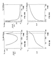
- Figs. 5A and 5B show the differential temperature ⁇ s - ⁇ measured as a function of the elapsing time using abnormal plasma as liquid to be tested, with the sensor heating current of about 40mA
- Figs. 6A and 6B are similar to Figs. 5A and 5B except that normal plasma was used as liquid to be tested with the sensor heating current of about 40mA.
- 10% means that a quantity of normal plasma was diluted 10 times by physiological saline so as to prepare a sample of plasma just as collected from a patient at extreme morbidity (e.g., almost at dead condition) and 100% means that the sample comprises only normal plasma.
- clotting factor stimulator comprising kaolin, phospholipid, cerite, silicic acid, elaidic acid or the like, and then the activated partial thromboplastin time (APTT) was measured.
- Each quantity of liquid to be tested was prepared in a tube (diameter 8mm) provided with metallic wire serving as the sensor and the sensor was heated by applying thereto current of about 40mA.
- Figs. 7A and 7B show the differential temperature ⁇ s - ⁇ ⁇ measured as a function of the elapsing time using abnormal plasma as liquid to be tested, with the sensor heating current of about 40mA
- Figs. 8A and 8B are similar to Figs. 7A and 7B except that normal plasma was used as liquid to be tested with the sensor heating current of about 40mA.
- the activated partial thromboplastin times were determined to be 176.0 sec and 32.1 sec, respectively, in the same manner as in EXAMPLE 1.
- a series of plasma samples was prepared by adjusting their fibrin contents stepwise from 1% to 20% of that normally found in healthy human plasma through dilution thereof by physiological saline, and the thrombin time was determined on these sample by injection-adding 0.2ml of clotting factor stimulator to 0.1ml of the respective samples and applying the sensor with current of about 60mA.
- Figs. 9A and 9B show the differential temperature ⁇ s - ⁇ as a function of the elapsing time in the sample of which the fibrin content is 1% of that normally found in healthy human plasma
- Figs. 10A and 10B show the result obtained on the sample of which the fibrin content is 20% of that normally found in healthy human plasma.
- the thrombin times were determined, on the samples of which the respective fibrin contents are 2% and 10% of that normally found in healthy human plasma, to be 54.3sec and 7.7sec, respectively.
- a viscosity change occurring in blood or the like can be detected by determining a change in the value of ⁇ s - ⁇ ⁇ .
- Determination of a change in the kinematic viscosity ⁇ permits a change in the viscosity of blood or the like to be detected, by finding a point of inflection in the same manner as in the case of ⁇ s - ⁇ ⁇ , since the kinematic viscosity ⁇ can be expressed as a function only of the heat flux "Q" and ⁇ s - ⁇ ⁇ by the equation (8).
- the heat transfer coefficient ⁇ and ⁇ s - ⁇ ⁇ are reciprocal to each other, since these are in the mutual relationship as expressed by the equation (1). Accordingly, a relationship between a variation of the heat transfer coefficient ⁇ and the time "t" can be plotted as a graphic diagram which is reciprocal to the above-mentioned Figs. 5A, 6A, 7A, 8A, 9A and 10A, and a point of inflection may be determined in the same manner as in the case of ⁇ s - ⁇ ⁇ to detect the viscosity change occurring in blood or the like, as seen in Fig. 12.
- ⁇ w - ⁇ Co′( ⁇ w - ⁇ ⁇ ) C1′ (14) It will be appreciated from this equation (14) that ⁇ w - ⁇ ⁇ is a function of ⁇ s - ⁇ ⁇ and, just as in the case of ⁇ s - ⁇ ⁇ , a point of inflection may be determined along the curve of ⁇ w - ⁇ ⁇ to detect a viscosity change occurring in blood or the like.
- ⁇ s or ⁇ ⁇ changes generally as shown by Fig. 11 as the viscosity of blood or the like changes, when the clotting factor stimulator is injection-added to the sample of healthy human blood and then the prothrombin time (PT) is determined.
- PT prothrombin time
- Fig. 12 shows how the heat transfer coefficient ⁇ changes with respect to variation of ⁇ s and ⁇ w shown in Fig. 11 and the coagulation time (Tc) can be determined by finding a point of inflection along a curve plotted by the heat transfer coefficient ⁇ .
- the viscosity change of blood or the like can be easily determined also from respective variations of ⁇ s, ⁇ w, ⁇ w - ⁇ ⁇ , ⁇ and ⁇ .
- the method of the present invention enables the viscosity change being important to know actual condition of blood or the like to be easily and exactly detected without interposition of any human subjective judgment.
- the other conditions of blood such as the blood type can be also easily identified by the method of the invention, because the manner of coagulation depends on a particular blood type.
- the method of the invention further enables even a small variation occurring in blood to be easily detected, thus minimizing an error possibly occurring in diagnostic measurement and allowing the blood diagnosis to be performed over a wide range.
- the method of the invention effectively simplifies the procedure of measurement and, therefore, measurement may be repeated to improve the accuracy.
- the method of the invention simplifies the construction of the equipment, particularly, the detection sensor used for measurement and correspondingly reduces the cost with respect to the prior art.
- the method of the invention is not limited to such manner of stimulation and antigen or antibody may be brought into contact with or added into blood or the like to stimulate the latter.
- antigen or antibody may be brought into contact with or added into blood or the like to stimulate the latter.
- IgG may be used as the antibody and fixed onto the sensor surface, so as to react with lactopherin so that quantity of lactopherin can be measured.
- Stimulation of blood or the like may be also achieved by suitable physical means, for example, by use of high frequency vibration acting on blood or the like or by heating blood or the like itself.
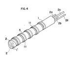
- Figs. 2 through 4 illustrate one embodiment of the sensor constructed according to the present invention.
- 1 designates a cylindrical electric insulator
- 2a and 2b or 2c and 2d designates a pair of lead wire extending through said electric insulator 1
- 3 designates platinum wire noninductively wound around the electric insulator 1 so as to form a measuring section "S′”.
- the pair of lead wire 2a and 2b or 2c and 2d extend from a rear end 1 ⁇ through the electric insulator 1 slightly beyond a front end 1′ of said electric insulator 1 and then U-turn again to extend through said electric insulator 1 beyond said rear end 1 ⁇ .
- Opposite ends of the platinum wire 3 are electrically connected to two pair of lead wire at their respective U-turn sections by means of spot welding or the like.
- the measuring section "S′" around which the platinum wire 3 is wound is coated with glass layer 4.
- Fig. 4 illustrates a variant of the sensor constructed in accordance with the present invention.
- the platinum wire 3 is noninductively wound around the electric insulator 1 which is, in turn, coated with synthetic resin layer 11.
- the sensor of the present invention is made in a manner as will be described below.
- a ceramic hollow rod having a length of 50mm and a diameter of 1.4mm is used as the electric insulator 1 and the platinum wire having a diameter of 13 ⁇ m is noninductively wound around said ceramic hollow rod so as to define at its front end the measuring section "S′" extending axially along the ceramic hollow rod over a length of 3mm.
- Glass pipe is fit around this assembly and heated to be deposited thereon or said assembly is immersed in liquid glass.
- said assembly may be immersed in resinous monomer dispersed system, then the platinum wire may be heated by energization to promote thermal polymerization around the outer surface of the platinum wire and thereby to form resinous polymer layer around the platinum wire.
- the sensor being capable of analyzing even a small quantity of sample with a high sensibility.
- the sensor of this invention may be used in accordance with the procedure as has been described in reference with Fig. 1 to detect the viscosity change in blood or the like.
- the sensor "S” is applied with current so as to maintain the heat flux "Q" constant and thereby a variation of the differential temperature ⁇ s - ⁇ ⁇ between blood and the surface of sensor can be determined.
- the heat flux "Q” is constant so as to keep the direct electric current "i” constant. Based on this variation of ⁇ s - ⁇ ⁇ , it is possible to determine the viscosity change occurring in blood or the like.
- variable values such as ⁇ w, ⁇ s, ⁇ w - ⁇ ⁇ , ⁇ and ⁇ can be calculated from the previously mentioned equations and these numerical values also enable the viscosity change in blood or the like to be determined.
- the senor of this invention is advantageous in that even a small quantity of sample can be analyzed with a high sensibility and that adhesion of blood ingredients onto the sensor can be sufficiently reduced to facilitate cleaning thereof because the sensor surface is coated with glass or synthetic resin.
Abstract
Description
- The present invention relates to a method for measurement of viscosity change, for example, a blood coagulation process, as well as a sensor used to perform said method.
- Generally, determination of a viscosity change occurring in blood or the like is important to know actual conditions of blood or the like and, for example, enables a blood type to be easily identified.
- Furthermore, the determination of the viscosity change has been commonly used to diagnose so-called hyperviscosity diseases such as cerebral infarction and myocardinal infarction.
- Especially, blood coagulation is particularly important and determination of the coagulation time has been most commonly used for diagnosis of various diseases such as haemophilia, von Willebrand's disease, Christmas disease and hepatic diseases. Pathologically, it has also been put in practice to know a condition of immune reaction by reacting plasma in blood with antigen or antibody.
- Typical method for measurement of blood coagulation time which have conventionally employed include those relying on measurement of prothrombin time (PT), measurement of activated partial thromboplastin time (APTT), measurement of thrombin time, fibrinogen test and hepaplastin test.
- Typical methods for examination of immune reaction include those relying on examination or measurement of complement supply reaction, fluorescent reaction and enzyme immunity.
- With the conventional methods for measurement of viscosity change in blood or the like, determination of coagulation or other phenomena have been macrographically made in most cases, even through these methods have utilized stimulators and test reagents which are commercially available and contain therein predetermined stabilized ingredients. Subjective judgment of the operator has necessarily limited the reliability of measurements and the measuring procedure usually repeated to improve such reliability of measurement has often resulted in unevenness of the measurements.
- It is also well known to measure blood coagulation time by use of a mechanical apparatus, for example, through determination of prothrombin time by use of spectrophotometer. However, such method of well known art is disadvantageous in that any disturbance on top of liquid to be tested will cause light scattering which, in turn, will cause a measurement error.
- Not only this method utilizing the spectrophotometer but also the other methods of prior art by which the blood coagulation time is measured by use of the mechanical apparatus have inconveniently been complicated also in their mechanisms.
- The inventors disclosed a method for measurement of physical property change occurring in liquid or the like in Japanese Disclosure Gazette No. 1985-152943. The disclosed invention proposes, as a part thereof, the method closely related to the present invention, i.e., the method for detection of any thrombus formed on the inner wall of artificial blood vessel through a change of heat transfer coefficient as sensed by a sensor utilizing metallic wire which is fixedly arranged in the inner wall of said artificial blood vessel. However, such method intends only to detect formation of thrombus on the inner wall of the artificial blood vessel but not to detect any abnormal condition occurring in blood or plasma itself.
- A primary object of the present invention is to overcome the above-mentioned disadvantages by providing a method for measurement of a viscosity change occurring in blood or the like and a sensor used to perform the method which can be commonly used for various kinds of measurement concerning the viscosity change in blood or the like, without being prone to erroneous measurement.
- According to the present invention, the above-mentioned object is achieved by a method for measurement of viscosity change in blood or the like, said method comprising steps of disposing a sensor comprising an endothermic or exothermic element in blood or the like, stimulating said blood or the like so as to cause a viscosity change therein and detecting said viscosity change by continuously measuring any one of changes occurring respectively in a average temperature ϑ w or a surface temperature ϑ s of said sensor containing therein the endothermic or exothermic element, a differential temperature ϑ w - ϑ∞ or ϑ s - ϑ∞ between a temperature ϑ∞ of blood or the like and ϑ w or ϑ s, a kinematic viscosity ν of blood or the like and a heat transfer coefficient α on said sensor surface.
- Such method for measurement of viscosity change in blood or the like may be effectively performed by using a sensor for measurement of viscosity change on blood or the like comprising an electric insulator through which lead wire extends, metallic wire wound around said electric insulator, said metallic wire being connected at opposite ends to the portions of said lead wire exposed on the surface of said electric insulator, and a portion of said electric insulator around which the metallic wire is wound being coated, or by using the other suitable sensors, for example, the sensor corresponding to the sensor as disclosed in US Patent Application Serial No. 224099 but miniaturized to the order of φ = 0.6mm and ℓ = 4mm.
- Generally, a major portion of the time required for blood coagulation is a period elapsing before formation of activated thromboplastin in blood and the reaction slowly goes on. Thereafter, transformation from fibriogen to fibrin rapidly occur. Then, blood loses its fluidity and becomes coagulated.
- During such process of blood coagulation, a viscosity change occurs in blood and simultaneously various values related to the sensor comprising the endothermic or exothermic element and disposed in blood also correspondingly change. Specifically, for example the average temperature ϑ w of the sensor, the surface temperature ϑ s of the sensor, the differential temperature ϑ w - ϑ∞ or ϑ s -ϑ∞ between the temperature of fluid such as blood and ϑ w or ϑ s, respectively, and the heat transfer coefficient α on the surface of the sensor change in their respective numerical values.
- It is also well known that the changes in these numerical values are in functional relationship with the kinematic viscosity of blood (see Introduction in "Journal of National Food Engineering Society", January, 1988).
- Thus, these changes may be determined intermittently or continuously to obtain a kinematic viscosity or an index value related to the kinematic viscosity and thereby to detect a viscosity change of blood.
- In immunity reaction system, the immunity reaction will be measured as a blood viscosity changes by the sensor in the same manner as has been mentioned above, or the sensor having antibody such as IgG fixed on the surface thereof so as to react with lactopherin contained in plasma, when a plurality of spheric plastic-latex particles are added into blood so that antigen/antibody reaction may occur on surfaces or these spheric particles which are then agglutinated together as a result of this reaction.
- These and other objects as well as advantages of the present invention will become clear by the following description of preferred embodiments of the present invention with reference to the accompanying drawings, wherein:
- Fig. 1 is a schematic diagram illustrating, partially in section, how the sensor constructed in accordance with the present invention is used;
- Fig. 2 is a perspective view of the sensor constructed as one embodiment of the present invention;
- Fig. 3 is a detailed view corresponding to Fig. 2 being partially broken away;
- Fig. 4 is a perspective view of the sensor constructed as another embodiment of the present invention;
- Figs. 5A and 6A are graphic diagrams respectively plotting the prothrombin time using abnormal plasma nd normal plasma, in which the ordinate indicates a difference Δ ϑ = ϑ s - ϑ ∞ and the abscissa indicated elapsing time;
- Figs. 5B and 6B are graphic diagrams respectively plotting the changing rates of Δ ϑ with respect to the elapsing time given in Figs. 5A and 6A, in which the ordinate indicates

- Figs. 7A and 8A are graphic diagrams respectively plotting the activated partial thromboplastin time using abnormal plasma which is made from normal plasma through dilution by physicological saline and normal plasma, in which the ordinate indicates a difference Δ ϑ = ϑ s - ϑ ∞ and the abscissa indicated elapsing time;
- Figs. 7B and 8B are graphic diagrams respectively plotting the changing rate of said Δ ϑ with respect to the elapsing time given in Figs. 7A and 8A, in which the ordinate indicates

- Figs. 9A and 10A are graphic diagrams respectively plotting the thrombin time using human normal plasma samples having fibrin content of 1% and 20%, in which the ordinate indicates a difference Δ ϑ = ϑ s - ϑ ∞ and the abscissa indicates elapsing time;
- Figs. 9B and 10B are graphic diagrams respectively plotting the changing rate of said Δ ϑ with respect to the elapsing time given in Figs. 9A and 10A, in which the ordinate indicates

- Fig. 11 is a graphic diagram roughly plotting the changes of ϑ s and ϑ w with respect to the prothrombin time (PT) of normal blood; and
- Fig. 12 is a graphic diagram roughly plotting the change in the heat transfer coefficient with respect to the changes of ϑ s and ϑ w as illustrated in Fig. 11.
- First, the method according to the present invention will be discussed in reference with Fig. 1 and Figs. 5 through 10.
- It has already been described that the variable values ϑ s, ϑ w, ϑ s - ϑ ∞ , ϑ w - ϑ ∞ , α and ν change as blood viscosity changes.
- Now, a relationship between the differential value ϑ s - ϑ ∞ (ϑ s : sensor surface temperature; ϑ∞ : blood temperature) and the kinematic viscosity of blood will be considered by way of example.
- Concerning the relationship established between the steady state heat transfer coefficient α and the difference ϑ s - ϑ ∞ , the steady state heat transfer coefficient α is given by a following equation:

- Accordingly, if both "Q" and "A" in equation (1) are known, the heat transfer coefficient α can be obtained from said differential temperature ϑ s - ϑ∞.
- It should be understood that, when the sensor is cylindrical, the sensor surface area "A" can be calculated so far as the diameter "d" and the length "ℓ" of this cylindrical sensor are known, because A ≒ π dℓ in such case.
- Then, the relationship between the differential temperature ϑ s - ϑ ∞ and the kinematic viscosity ν will be considered.
- The sensor is disposed, for example, in stationary distilled water of which the physical property values is already known, and then applied with constant current, e.g., DC constant current which may have various values while a differential temperature ϑ s - ϑ ∞ between said distilled water and the (heated) sensor is measured. This procedure allows a relationship to be established among the Nusselt number Nu corresponding to the dimensionless number of the heat transfer coefficient, the Prandtl number Pr corresponding to the dimensionless number of the kinematic viscosity and the Grashof number Gr corresponding to the dimensionless number of the temperature difference, i.e., an equation generally representing free convection heat transfer around said sensor in the form, for example, of
Nu = Co GrC1 PrC2 (2)
where Co, C1 and C2 represent constants. - Nu, Gr and Pr can be expressed by following equations:
Nu = α L/λ (3)
Gr = L³gβ (ϑ s - ϑ ∞ )/ν ² (4)
Pr = ν /a (5)
where "L" represents typical length (m), λ represents thermal conductivity (W/mK), "g" represents gravitational acceleration (m/s²), β represents coefficient of volumetric expansion (1/K), represents kinematic viscosity (m²/s), and "a" represents thermal diffusivity (m²/s). - Accordingly, from the equations (2) through (5) as set forth above, the kinematic viscosity can be expressed by a following equation: ν2C1 - C2 = C0̸g C1AL3C1-1Q⁻¹ λ βC1a -C2 (ϑ s - ϑ ∞) C1+1 (6)
- When platinum wire adapted to be applied with current "i" and thereby to be heated is employed as the sensor,
Q = Ri² (7)
where "R" represents the electric resistance (Ω) of the platinum wire used as the sensor and "i" represents the value "A" of direct electric current applied to the sensor. - In the above-mentioned equation (6), g, "A" and "L" represent constants.
- Further when the fluid include a large quantity of water or the composition of the fluid remain relatively unchanged, it can be assumed that λ, β and α respectively change in ranges sufficiently smaller that the renge in which changes, so that the kinematic viscosity ν can be ultimately expressed by a following equation as a function exclusively of the differential temprature ϑ s - ϑ ∞ and the heat flux "Q":
ν2C1-C2 = C₃Q⁻¹ (ϑ s - ϑ ∞) C1+1 (8)
where C₃ represents a constant. - Using blood as the fluid (F) and applying the sensor (S) with current so as to maintain the heat flux "Q" constant, the differential temperature ϑ s - ϑ∞ between blood and the surface of the sensor may be measured to obtain a kinematic viscosity ν and thereby to detect a change in blood viscosity.
- The above-mentioned blood temperature ϑ∞ may be measured by use of the resistance thermometer comprising platinum and said ϑ s may be measured by employing the invention disclosed in the prior Japanese Disclosure Gazette No. 1988-217261 (corresponding to US Patent Application Serial No. 157261) of the inventors. Accordingly from Japanese Disclosure Gazette No.1988-21726 the relationship between the sensor surface temperature ϑ s and the sensor average temperature ϑ w is expressed by;
ϑ s = ϑ w - Ao·i²(1 + α wϑ w) (9)
where
α w : temperature coefficient of electric resistance
i : value of current applied to the sensor
Ao : constant
And ϑ w is expressed by
ϑ w = (V/i·Ro - 1)/α w (10)
where
Ro : electric resistance developed in the sensor metallic wire at 0°C
V : value of voltage across the sensor
Therefore, ϑ w can be calculated from the voltage value "V" and the current value "i" of the sensor, and ϑ s can be calculated from ϑ w. Furthermore, from equation (9) and (10) as set forth above, ϑ s can be expressed by a function of both the voltage value and the current value,
ϑ s = f(V, i) (11)
Accordingly, ϑ s can be calculated also from the voltage value and the current value. - When the blood temperature ϑ ∞ and the sensor average temperature ϑ w is measured by use of the resistance thermometer, ϑ s can be calculated also by using a following equation:
ϑ s = ϑ ∞ + Co′ (ϑ w - ϑ ∞)C1′ (12)
or ϑ s = ϑ ∞ + Co˝(ϑ w - ϑ ∞) (13)
Co′, Co˝, Cl′ : specific constants of the sensor - In this way, the viscosity change occurring in blood or the like can be determined by measuring the variable values of ϑ s, ϑ w, ϑ s - ϑ ∞ , ϑ w - ϑ ∞ , α and ν . Now a method for determination of a viscosity change and, therefore, a specific coagulation time of blood from a change of ϑ s - ϑ ∞ , based on a result of the experiment conducted in connection with ϑ s - ϑ ∞ , will be explained.
- For the experiment, an apparatus as shown by Fig.1 was used.
- Referring to Fig. 1, a sensor "S" is placed in a quantity of fluid "F" such as blood contained in a
vessel 10 and, in a measuring system "M", a pair ofcurrent lead wire current source 5 for energization while another pair ofvoltage lead wires potentiometer 6 for voltage measurement so that electrical resistance of the sensor can be measured on the basis of four wire method. - In the measuring system "M", the
DC power source 5, thedigitalvoltmeter 6 and acontroller 7 are connected one to another by GP-IB (general purpose interface bus). - With the platinum wire 3 being applied with current so as to maintain the heat flux thereof constant, by continuously measuring values of voltage impressed to the platinum wire 3, the sensor average temperature ϑ s, the differential temperature ϑ s - ϑ∞ between flood and the surface of the sensor, and the differential temperature ϑ w - ϑ ∞ between flood and the sensor is determined from the equations (9) through (13).
- Additionally there is the difference between the method of measuring the blood temperature ϑ ∞ by one sensor and that by two sensor, which is described as follows;
In case of one sensor, - Step 1; the sensor is applied with direct current of about 100 µ A or 1mA.
-
Step 2; the measurement of voltage values V impressed to the platinum wire of the sensor. - Step 3; the blood temperature ϑ∞ can be calculated from the equation (10) and the voltage value V.
-
Step 4; further the sensor is applied with direct current of more than 1mA i.e., 20mA or 60mA. -
Step 5; the same asStep 2. -
Step 6; the sensor average temperature ϑ w can be calculated by the same method of Step 3. -
Step 7; the differential temperature ϑ s - ϑ ∞ can be calculated from the equation (12). - Repeating the measurement and the calculation of
Step 5 through 7, the changing value of ϑ s -ϑ ∞ with respect to the elapsing time can be obtained.
In case of two sensor S₁, S₂, - Step 1: the sensor S₁ is applied with direct current of about 100µ A or 1mA
- Step 2: the measurement of voltage values V₁ impressed to the platinum wire of the sensor S₁.
- Step 3: the blood temperature ϑ ∞ can be calculated from the equation (10) and the voltage value V₁.
- Step 4: the sensor S₂ is applied with direct current of more than 1mA, i.e., 20mA or 60mA.
- Step 5: the measurement of voltage value V₂ impressed to the platinum wire of the sensor S₂.
- Step 6: the sensor average temperature ϑ w can be calculated from the equation (10) and the voltage value V₂.
- Step 7: the differential temperature ϑ s - ϑ ∞ can be calculated from the equation (12).
- Repeating the measurement and the calculation of
Step 2 through 3 andStep 5 through 7, the changing value of ϑ s - ϑ ∞ with respect to the elapsing time can be obtained. - While the sensor as has been described in reference with Figs. 2 through 4 was used in this embodiment, any other types of sensor may be used so far as the sensor comprises an endothermic element or an exothermic element.
- The result of the experiments conducted by the inventors will be set forth below.
- In the experiments of the inventors, samples of human normal plasma (VNC) were injection-added with various reagents and coagulation processes occurring thereafter were continuously measured by use of the sensor.
- Each 0.1ml of normal whole blood, normal plasma, abnormal whole blood and abnormal plasma was mixed-injection-added with 0.2ml of clotting factor stimulator such as tissue thromboplastin and calcium chloride, and then the prothrombin time (PT) was measured.
- Each quantity of liquid to be tested was prepared in a tube (diameter 8mm) provided with the sensor comprising platinum wire which presents electric resistance of 50Ω at a temperature of 0°C, and the sensor was heated by applying thereto direct electric current of about 40mA or about 60mA.
- Figs. 5A and 5B show the differential temperature ϑ s - ϑ∞ measured as a function of the elapsing time using abnormal plasma as liquid to be tested, with the sensor heating current of about 40mA, and Figs. 6A and 6B are similar to Figs. 5A and 5B except that normal plasma was used as liquid to be tested with the sensor heating current of about 40mA.
- In the experiment corresponding to Figs. 5A, 5B and Figs. 6A, 6B, a point of inflection at which the changing rate of the differential temperature ϑ s - ϑ ∞ sharply decreases as the time elapses was determined as a fixed point and thereby the prothrombin time (PT) was measured to be 34.6 sec and 13.0 sec, respectively.
Table 1 10 % 100% Pt, VNC 34.6 sec 13.0 i = 40mA (Fig. 5) (Fig. 6) - Each 0.2ml of normal whole blood, normal plasma, abnormal whole blood and abnormal plasma was mixed-injection-added with 0.1ml of clotting factor stimulator comprising kaolin, phospholipid, cerite, silicic acid, elaidic acid or the like, and then the activated partial thromboplastin time (APTT) was measured.
- Each quantity of liquid to be tested was prepared in a tube (diameter 8mm) provided with metallic wire serving as the sensor and the sensor was heated by applying thereto current of about 40mA.
- Figs. 7A and 7B show the differential temperature ϑ s - ϑ ∞ measured as a function of the elapsing time using abnormal plasma as liquid to be tested, with the sensor heating current of about 40mA, and Figs. 8A and 8B are similar to Figs. 7A and 7B except that normal plasma was used as liquid to be tested with the sensor heating current of about 40mA.
- In the experiments respectively corresponding to Figs. 7A, 7B and Figs. 8A, 8B, the activated partial thromboplastin times (APTT) were determined to be 176.0 sec and 32.1 sec, respectively, in the same manner as in EXAMPLE 1.
Table 2 10 % 100 % APTT, VNC 176.0 sec 32.1 sec i = 40mA (Fig. 7) (Fig. 8) Meaning of 10% and 100% are same as in Table 1. - A series of plasma samples was prepared by adjusting their fibrin contents stepwise from 1% to 20% of that normally found in healthy human plasma through dilution thereof by physiological saline, and the thrombin time was determined on these sample by injection-adding 0.2ml of clotting factor stimulator to 0.1ml of the respective samples and applying the sensor with current of about 60mA.
- Figs. 9A and 9B show the differential temperature ϑ s - ϑ∞ as a function of the elapsing time in the sample of which the fibrin content is 1% of that normally found in healthy human plasma, and Figs. 10A and 10B show the result obtained on the sample of which the fibrin content is 20% of that normally found in healthy human plasma.
- In these experiments of which the results are shown by Figs. 9A, 9B and Figs. 10A, 10B, the thrombin times were also determined in the same manner as in Example 1 to be 151.3sec and 3.4sec, respectively.
- Similarly, the thrombin times were determined, on the samples of which the respective fibrin contents are 2% and 10% of that normally found in healthy human plasma, to be 54.3sec and 7.7sec, respectively.
- As apparent from three Examples as have been described above, a viscosity change occurring in blood or the like can be detected by determining a change in the value of ϑ s - ϑ ∞.
- Determination of a change in the kinematic viscosity ν permits a change in the viscosity of blood or the like to be detected, by finding a point of inflection in the same manner as in the case of ϑ s - ϑ ∞ , since the kinematic viscosity ν can be expressed as a function only of the heat flux "Q" and ϑ s - ϑ ∞ by the equation (8).
- The heat transfer coefficient α and ϑ s - ϑ ∞ are reciprocal to each other, since these are in the mutual relationship as expressed by the equation (1). Accordingly, a relationship between a variation of the heat transfer coefficient α and the time "t" can be plotted as a graphic diagram which is reciprocal to the above-mentioned Figs. 5A, 6A, 7A, 8A, 9A and 10A, and a point of inflection may be determined in the same manner as in the case of ϑ s - ϑ ∞ to detect the viscosity change occurring in blood or the like, as seen in Fig. 12. For example, concerning ϑ w - ϑ∞, transferring ϑ∞ from the right side to the left side in the equation (12) results in a following equation:
ϑ s - ϑ∞ = Co′(ϑ w -ϑ ∞)C1′ (14)
It will be appreciated from this equation (14) that ϑ w - ϑ ∞ is a function of ϑ s - ϑ ∞ and, just as in the case of ϑ s - ϑ ∞ , a point of inflection may be determined along the curve of ϑ w - ϑ ∞ to detect a viscosity change occurring in blood or the like. - ϑ s or ϑ ∞ changes generally as shown by Fig. 11 as the viscosity of blood or the like changes, when the clotting factor stimulator is injection-added to the sample of healthy human blood and then the prothrombin time (PT) is determined. Thus, it is also possible to detect the viscosity change of blood or the like by finding a point of inflection along a curve plotted by the value of ϑ s or ϑ ∞ varying as the viscosity of blood or the like changes. It should be understood that Fig. 12 shows how the heat transfer coefficient α changes with respect to variation of ϑ s and ϑ w shown in Fig. 11 and the coagulation time (Tc) can be determined by finding a point of inflection along a curve plotted by the heat transfer coefficient α .
- In this manner, the viscosity change of blood or the like can be easily determined also from respective variations of ϑ s, ϑ w, ϑ w - ϑ ∞, α and ν .
- As will be apparent from the foregoing description, the method of the present invention enables the viscosity change being important to know actual condition of blood or the like to be easily and exactly detected without interposition of any human subjective judgment.
- With a consequence, the other conditions of blood such as the blood type can be also easily identified by the method of the invention, because the manner of coagulation depends on a particular blood type.
- Additionally, as has been discribed in reference with Fig. 7 and 9, even a patient being in such serious condition that the blood coagulation time tends to be prolonged can be diagnosed almost independently of any influence by the inevitable low viscosity. The method of the invention further enables even a small variation occurring in blood to be easily detected, thus minimizing an error possibly occurring in diagnostic measurement and allowing the blood diagnosis to be performed over a wide range.
- The method of the invention effectively simplifies the procedure of measurement and, therefore, measurement may be repeated to improve the accuracy.
- Moreover, the method of the invention simplifies the construction of the equipment, particularly, the detection sensor used for measurement and correspondingly reduces the cost with respect to the prior art.
- While the viscosity change of blood or the like was caused by stimulating blood or the like with addition of clotting factor stimulator in the previously mentioned Examples 1 through 3 of the method according to the present invention, the method of the invention is not limited to such manner of stimulation and antigen or antibody may be brought into contact with or added into blood or the like to stimulate the latter. For example, IgG may be used as the antibody and fixed onto the sensor surface, so as to react with lactopherin so that quantity of lactopherin can be measured.
- Stimulation of blood or the like may be also achieved by suitable physical means, for example, by use of high frequency vibration acting on blood or the like or by heating blood or the like itself.
- Now the sensor of the present invention will be described in reference with Figs. 2 through 4 which illustrate one embodiment of the sensor constructed according to the present invention. Referring to Figs. 2 and 3, 1 designates a cylindrical electric insulator, 2a and 2b or 2c and 2d designates a pair of lead wire extending through said electric insulator 1, and 3 designates platinum wire noninductively wound around the electric insulator 1 so as to form a measuring section "S′".
- The pair of
lead wire - The measuring section "S′" around which the platinum wire 3 is wound is coated with
glass layer 4. - Fig. 4 illustrates a variant of the sensor constructed in accordance with the present invention. In this embodiment, the platinum wire 3 is noninductively wound around the electric insulator 1 which is, in turn, coated with synthetic resin layer 11.
- The sensor of the present invention is made in a manner as will be described below.
- A ceramic hollow rod having a length of 50mm and a diameter of 1.4mm is used as the electric insulator 1 and the platinum wire having a diameter of 13µ m is noninductively wound around said ceramic hollow rod so as to define at its front end the measuring section "S′" extending axially along the ceramic hollow rod over a length of 3mm. Glass pipe is fit around this assembly and heated to be deposited thereon or said assembly is immersed in liquid glass. Alternatively, said assembly may be immersed in resinous monomer dispersed system, then the platinum wire may be heated by energization to promote thermal polymerization around the outer surface of the platinum wire and thereby to form resinous polymer layer around the platinum wire. Here is provided thereby the sensor being capable of analyzing even a small quantity of sample with a high sensibility.
- The sensor of this invention may be used in accordance with the procedure as has been described in reference with Fig. 1 to detect the viscosity change in blood or the like.
- Specifically, blood is used as the fluid "F", the sensor "S" is applied with current so as to maintain the heat flux "Q" constant and thereby a variation of the differential temperature ϑ s - ϑ ∞ between blood and the surface of sensor can be determined. Moreover, on the grounds that the sensor average temperature ϑ w in unchangeable, it can be assumed that the heat flux "Q" is constant so as to keep the direct electric current "i" constant. Based on this variation of ϑ s -ϑ ∞, it is possible to determine the viscosity change occurring in blood or the like.
- Furthermore, the variable values such as ϑ w, ϑ s, ϑ w - ϑ ∞ , α and ν can be calculated from the previously mentioned equations and these numerical values also enable the viscosity change in blood or the like to be determined.
- Experimental use for detection of the viscosity change in blood or the like indicated that the sensor of this invention actually provides the effect just as has previously been described in connection with the method of the invention for detection of the blood viscosity change.
- Finally, the sensor of this invention is advantageous in that even a small quantity of sample can be analyzed with a high sensibility and that adhesion of blood ingredients onto the sensor can be sufficiently reduced to facilitate cleaning thereof because the sensor surface is coated with glass or synthetic resin.
- while there has been described what is at present considered to be preferred embodiment of the invention, it will be understood that various modifications may be made therein, and it is intended to cover in the appended claims all such modifications as fall within the true spirit and scope of the invention.
Claims (9)
Applications Claiming Priority (4)
| Application Number | Priority Date | Filing Date | Title |
|---|---|---|---|
| JP53082/88 | 1988-03-07 | ||
| JP63053082A JPH0650317B2 (en) | 1988-03-07 | 1988-03-07 | Measuring method of viscosity change of blood etc. |
| JP64776/88 | 1988-03-18 | ||
| JP63064776A JPH01239433A (en) | 1988-03-18 | 1988-03-18 | Sensor for measuring change in viscosity of blood or the like |
Publications (3)
| Publication Number | Publication Date |
|---|---|
| EP0332110A2 true EP0332110A2 (en) | 1989-09-13 |
| EP0332110A3 EP0332110A3 (en) | 1992-12-23 |
| EP0332110B1 EP0332110B1 (en) | 1996-03-06 |
Family
ID=26393790
Family Applications (1)
| Application Number | Title | Priority Date | Filing Date |
|---|---|---|---|
| EP89103900A Expired - Lifetime EP0332110B1 (en) | 1988-03-07 | 1989-03-06 | Method for measurement of viscosity change in blood or blood plasma and sensor therefor |
Country Status (4)
| Country | Link |
|---|---|
| US (1) | US4947678A (en) |
| EP (1) | EP0332110B1 (en) |
| CA (1) | CA1333754C (en) |
| DE (1) | DE68925829T2 (en) |
Cited By (6)
| Publication number | Priority date | Publication date | Assignee | Title |
|---|---|---|---|---|
| EP0460214A1 (en) * | 1989-02-23 | 1991-12-11 | Kurita Water Industries Ltd. | Flocculating apparatus |
| EP0476923A1 (en) * | 1990-09-14 | 1992-03-25 | Sankyo Company Limited | Blood coagulation time measurement |
| EP0775311A4 (en) * | 1993-08-31 | 1996-08-30 | Boehringer Mannheim Corp | Analog heater control for medical instrument |
| US6189370B1 (en) | 1993-08-31 | 2001-02-20 | Roche Diagnostics Corporation | Fluid dose, flow and coagulation sensor for medical instrument |
| EP1845372A2 (en) * | 1997-01-08 | 2007-10-17 | Bristol-Myers Squibb Company | A method for indirectly determining the temperature of blood |
| FR3018604A1 (en) * | 2014-03-17 | 2015-09-18 | Auxitrol Sa | METHOD FOR MANUFACTURING SENSITIVE ELEMENT, SENSITIVE ELEMENT AND CORRESPONDING MEASURING DEVICE |
Families Citing this family (23)
| Publication number | Priority date | Publication date | Assignee | Title |
|---|---|---|---|---|
| CA2066855A1 (en) * | 1991-04-22 | 1992-10-23 | Norio Kawanami | Method and apparatus for measurement of polymer molecular weight |
| JP2594874B2 (en) * | 1993-03-26 | 1997-03-26 | 雪印乳業株式会社 | Simultaneous measurement of thermal conductivity and kinematic viscosity |
| US5854423A (en) * | 1996-03-20 | 1998-12-29 | Venegas; Jose G. | Apparatus and method for assessment of visco-elasticity and shear adherence strength properties of blood clots |
| US5783447A (en) * | 1996-10-02 | 1998-07-21 | University Of Medicine And Dentistry Of New Jersey | Hypercoagulability comparative determinants obtained using detection systems with variable force-induced energy inputs |
| US5792660A (en) * | 1996-10-02 | 1998-08-11 | University Of Medicine And Dentistry Of New Jersey | Comparative determinants of viscosity in body fluids obtained with probes providing increased sensitivity |
| US6046051A (en) * | 1997-06-27 | 2000-04-04 | Hemosense, Inc. | Method and device for measuring blood coagulation or lysis by viscosity changes |
| US6322525B1 (en) | 1997-08-28 | 2001-11-27 | Visco Technologies, Inc. | Method of analyzing data from a circulating blood viscometer for determining absolute and effective blood viscosity |
| US6322524B1 (en) | 1997-08-28 | 2001-11-27 | Visco Technologies, Inc. | Dual riser/single capillary viscometer |
| US6019735A (en) | 1997-08-28 | 2000-02-01 | Visco Technologies, Inc. | Viscosity measuring apparatus and method of use |
| US6450974B1 (en) | 1997-08-28 | 2002-09-17 | Rheologics, Inc. | Method of isolating surface tension and yield stress in viscosity measurements |
| US6402703B1 (en) * | 1997-08-28 | 2002-06-11 | Visco Technologies, Inc. | Dual riser/single capillary viscometer |
| US6428488B1 (en) | 1997-08-28 | 2002-08-06 | Kenneth Kensey | Dual riser/dual capillary viscometer for newtonian and non-newtonian fluids |
| US6484565B2 (en) | 1999-11-12 | 2002-11-26 | Drexel University | Single riser/single capillary viscometer using mass detection or column height detection |
| US20030158500A1 (en) * | 1999-11-12 | 2003-08-21 | Kenneth Kensey | Decreasing pressure differential viscometer |
| US6412336B2 (en) | 2000-03-29 | 2002-07-02 | Rheologics, Inc. | Single riser/single capillary blood viscometer using mass detection or column height detection |
| US6484566B1 (en) | 2000-05-18 | 2002-11-26 | Rheologics, Inc. | Electrorheological and magnetorheological fluid scanning rheometer |
| US6695470B1 (en) * | 2002-09-10 | 2004-02-24 | Delphi Technologies, Inc. | Apparatus and method for viscosity measurement |
| WO2006063427A1 (en) * | 2004-12-16 | 2006-06-22 | Atlantic Business Centre Of Excellence And Commercialization Of Innovation Ltd. | Method and apparatus for monitoring materials |
| US20080297169A1 (en) * | 2007-05-31 | 2008-12-04 | Greenquist Alfred C | Particle Fraction Determination of A Sample |
| EP2271402A1 (en) * | 2008-03-31 | 2011-01-12 | St. Jude Medical AB | Anti-arrhythmia implantable medical device |
| US9869594B2 (en) * | 2012-11-05 | 2018-01-16 | Steamist, Inc. | Controller for steam bath having multiple temperature sensors |
| US11249068B2 (en) | 2015-11-09 | 2022-02-15 | Ohio State Innovation Foundation | Non-invasive method for detecting a deadly form of malaria |
| CN109211729A (en) * | 2018-10-29 | 2019-01-15 | 杨忠思 | A kind of blood stagnation condition checkout gear and method for precisely medical treatment detection |
Citations (5)
| Publication number | Priority date | Publication date | Assignee | Title |
|---|---|---|---|---|
| SU590665A1 (en) * | 1976-02-11 | 1978-01-30 | Новосибирский государственный медицинский институт | Method of investigating |
| US4497774A (en) * | 1981-06-19 | 1985-02-05 | Medical Laboratory Automation, Inc. | Coagulation instrument for performing clotting tests |
| SU1157456A1 (en) * | 1981-07-21 | 1985-05-23 | Научно-производственное объединение "Квант" | Method of investigating process of blood coagulation |
| EP0144443A1 (en) * | 1983-05-25 | 1985-06-19 | Snow Brand Milk Products Co., Ltd. | Method for measuring coagulation of milk |
| EP0214874A2 (en) * | 1985-09-06 | 1987-03-18 | Snow Brand Milk Products Co., Ltd. | Sensor for measurement by electrical heating |
Family Cites Families (10)
| Publication number | Priority date | Publication date | Assignee | Title |
|---|---|---|---|---|
| US845413A (en) * | 1906-09-22 | 1907-02-26 | Firm Of W C Heraeus | Electric-resistance thermometer. |
| US1860541A (en) * | 1929-11-08 | 1932-05-31 | Charles Engelhard Inc | Gas analysis apparatus |
| US2685015A (en) * | 1953-03-31 | 1954-07-27 | Paul G Weiller | Resistance thermometer element |
| US3516282A (en) * | 1966-04-19 | 1970-06-23 | Fielden Electronics Australia | Dewpoint detection apparatus |
| US3678751A (en) * | 1970-07-01 | 1972-07-25 | Carver A Mead | Thermometer probe |
| US3748624A (en) * | 1971-03-30 | 1973-07-24 | Nippon Denso Co | Pyrometric sensor using thermistor |
| US3821643A (en) * | 1973-05-29 | 1974-06-28 | Research Corp | Blood coagulation timer |
| GB1454816A (en) * | 1974-02-19 | 1976-11-03 | Rosemount Eng Co Ltd | Resistance thermometer sensors |
| JPS60152943A (en) * | 1984-01-20 | 1985-08-12 | Snow Brand Milk Prod Co Ltd | Measurement of change in physical properties of liquid and semi-solid substance |
| ATE61482T1 (en) * | 1986-08-14 | 1991-03-15 | Ciba Geigy Ag | METHOD AND DEVICE FOR DETERMINING THE GELLING BEHAVIOR OF A REACTIVE RESIN SYSTEM. |
-
1989
- 1989-03-06 US US07/319,192 patent/US4947678A/en not_active Expired - Lifetime
- 1989-03-06 DE DE68925829T patent/DE68925829T2/en not_active Expired - Fee Related
- 1989-03-06 CA CA000592887A patent/CA1333754C/en not_active Expired - Fee Related
- 1989-03-06 EP EP89103900A patent/EP0332110B1/en not_active Expired - Lifetime
Patent Citations (5)
| Publication number | Priority date | Publication date | Assignee | Title |
|---|---|---|---|---|
| SU590665A1 (en) * | 1976-02-11 | 1978-01-30 | Новосибирский государственный медицинский институт | Method of investigating |
| US4497774A (en) * | 1981-06-19 | 1985-02-05 | Medical Laboratory Automation, Inc. | Coagulation instrument for performing clotting tests |
| SU1157456A1 (en) * | 1981-07-21 | 1985-05-23 | Научно-производственное объединение "Квант" | Method of investigating process of blood coagulation |
| EP0144443A1 (en) * | 1983-05-25 | 1985-06-19 | Snow Brand Milk Products Co., Ltd. | Method for measuring coagulation of milk |
| EP0214874A2 (en) * | 1985-09-06 | 1987-03-18 | Snow Brand Milk Products Co., Ltd. | Sensor for measurement by electrical heating |
Non-Patent Citations (2)
| Title |
|---|
| Week 47, 1985 Derwent Publications Ltd., London, GB; AN 85-295416 & SU-A-1 157 456 (KVANT TRUST) 23 May 1985 * |
| Week 50, 1978 Derwent Publications Ltd., London, GB; AN 78-91120A & SU-A-590 665 (NOVOS MEDICINE INST.) 20 February 1978 * |
Cited By (14)
| Publication number | Priority date | Publication date | Assignee | Title |
|---|---|---|---|---|
| EP0460214A1 (en) * | 1989-02-23 | 1991-12-11 | Kurita Water Industries Ltd. | Flocculating apparatus |
| EP0460214A4 (en) * | 1989-02-23 | 1992-04-01 | Kurita Water Industries Pty. Ltd. | Flocculating apparatus |
| EP0476923A1 (en) * | 1990-09-14 | 1992-03-25 | Sankyo Company Limited | Blood coagulation time measurement |
| US6189370B1 (en) | 1993-08-31 | 2001-02-20 | Roche Diagnostics Corporation | Fluid dose, flow and coagulation sensor for medical instrument |
| EP0775311A1 (en) * | 1993-08-31 | 1997-05-28 | Boehringer Mannheim Corporation | Analog heater control for medical instrument |
| US5832921A (en) * | 1993-08-31 | 1998-11-10 | Boehringer Mannheim Corporation | Analog heater control for medical instrument |
| EP0775311A4 (en) * | 1993-08-31 | 1996-08-30 | Boehringer Mannheim Corp | Analog heater control for medical instrument |
| US6575017B1 (en) | 1993-08-31 | 2003-06-10 | Roche Diagnostics Corporation, Inc. | Fluid dose, flow and coagulation sensor for medical instrument |
| US7117721B2 (en) | 1993-08-31 | 2006-10-10 | Roche Diagnostics Operations, Inc. | Fluid dose, flow and coagulation sensor for medical instrument |
| EP1845372A2 (en) * | 1997-01-08 | 2007-10-17 | Bristol-Myers Squibb Company | A method for indirectly determining the temperature of blood |
| EP1845372A3 (en) * | 1997-01-08 | 2007-10-24 | Bristol-Myers Squibb Company | A method for indirectly determining the temperature of blood |
| FR3018604A1 (en) * | 2014-03-17 | 2015-09-18 | Auxitrol Sa | METHOD FOR MANUFACTURING SENSITIVE ELEMENT, SENSITIVE ELEMENT AND CORRESPONDING MEASURING DEVICE |
| WO2015140182A1 (en) * | 2014-03-17 | 2015-09-24 | Auxitrol S.A. | Method of manufacturing an element sensitive to a physical parameter of a flow of fluid and corresponding sensitive element |
| US10132667B2 (en) | 2014-03-17 | 2018-11-20 | Auxitrol S.A. | Method of manufacturing an element sensitive to a physical parameter of a flow of fluid and corresponding sensitive element |
Also Published As
| Publication number | Publication date |
|---|---|
| DE68925829T2 (en) | 1996-10-31 |
| EP0332110A3 (en) | 1992-12-23 |
| US4947678A (en) | 1990-08-14 |
| CA1333754C (en) | 1995-01-03 |
| EP0332110B1 (en) | 1996-03-06 |
| DE68925829D1 (en) | 1996-04-11 |
Similar Documents
| Publication | Publication Date | Title |
|---|---|---|
| EP0332110A2 (en) | Method for measurement of viscosity change in blood or blood plasma and sensor therefor | |
| US8465978B2 (en) | Method for conducting platelete aggregation analysis by a cartridge device | |
| EP0144443B1 (en) | Method for measuring coagulation of milk | |
| JP5122094B2 (en) | System for differential determination of proteolytic enzymes in body fluids | |
| US6066504A (en) | Coagulation or lysis assays using an electroactive species | |
| EP0494079B1 (en) | Quantification of fibrinogen in whole blood samples | |
| EP0738389A1 (en) | Apparatus and method for detecting coagulation/lysis of liquids | |
| CA2528362A1 (en) | Method and device for analysing a biological liquid | |
| EP1004020B1 (en) | Aggregometer with disposable test cell | |
| EP0150111A2 (en) | Method for measuring changes in a physical property of liquid and semisolid materials | |
| US3840806A (en) | Instrument for measuring blood clotting times | |
| JP2009233369A (en) | Method for calibration and measurement in micro-dialysis system | |
| EP1588161B1 (en) | System and method for measuring coagulation time without thermostatic control | |
| EP0356893B1 (en) | Method for measuring a gel-point temperature | |
| EP1432019A1 (en) | Method for producing a nanowire filament using electromigration | |
| US6150174A (en) | Method for measurement of whole blood coagulation parameters | |
| US4498305A (en) | Probe for measuring electrical conductance | |
| JPH0470577B2 (en) | ||
| JPH01227062A (en) | Measurement of change in viscosity for blood or the like | |
| JPS58149746A (en) | Syringe type living body sample analytical apparatus | |
| JP3194253B2 (en) | Surface state measuring device and method for measuring fluid state change using the same | |
| AU679934B2 (en) | Apparatus and method for detecting coagulation/lysis of liquids | |
| JPH0476428B2 (en) |
Legal Events
| Date | Code | Title | Description |
|---|---|---|---|
| PUAI | Public reference made under article 153(3) epc to a published international application that has entered the european phase |
Free format text: ORIGINAL CODE: 0009012 |
|
| AK | Designated contracting states |
Kind code of ref document: A2 Designated state(s): DE FR GB IT NL SE |
|
| PUAL | Search report despatched |
Free format text: ORIGINAL CODE: 0009013 |
|
| AK | Designated contracting states |
Kind code of ref document: A3 Designated state(s): DE FR GB IT NL SE |
|
| 17P | Request for examination filed |
Effective date: 19930121 |
|
| 17Q | First examination report despatched |
Effective date: 19931014 |
|
| RAP1 | Party data changed (applicant data changed or rights of an application transferred) |
Owner name: SNOW BRAND MILK PRODUCTS CO., LTD. |
|
| GRAH | Despatch of communication of intention to grant a patent |
Free format text: ORIGINAL CODE: EPIDOS IGRA |
|
| GRAA | (expected) grant |
Free format text: ORIGINAL CODE: 0009210 |
|
| AK | Designated contracting states |
Kind code of ref document: B1 Designated state(s): DE FR GB IT NL SE |
|
| REF | Corresponds to: |
Ref document number: 68925829 Country of ref document: DE Date of ref document: 19960411 |
|
| ITF | It: translation for a ep patent filed |
Owner name: NOVELTY SERVICE ING. DI IORIO G. |
|
| ET | Fr: translation filed | ||
| PLBE | No opposition filed within time limit |
Free format text: ORIGINAL CODE: 0009261 |
|
| STAA | Information on the status of an ep patent application or granted ep patent |
Free format text: STATUS: NO OPPOSITION FILED WITHIN TIME LIMIT |
|
| 26N | No opposition filed | ||
| PGFP | Annual fee paid to national office [announced via postgrant information from national office to epo] |
Ref country code: DE Payment date: 19990310 Year of fee payment: 11 |
|
| PGFP | Annual fee paid to national office [announced via postgrant information from national office to epo] |
Ref country code: GB Payment date: 19990315 Year of fee payment: 11 |
|
| PGFP | Annual fee paid to national office [announced via postgrant information from national office to epo] |
Ref country code: NL Payment date: 19990329 Year of fee payment: 11 |
|
| PG25 | Lapsed in a contracting state [announced via postgrant information from national office to epo] |
Ref country code: GB Free format text: LAPSE BECAUSE OF NON-PAYMENT OF DUE FEES Effective date: 20000306 |
|
| PGFP | Annual fee paid to national office [announced via postgrant information from national office to epo] |
Ref country code: FR Payment date: 20000314 Year of fee payment: 12 |
|
| PGFP | Annual fee paid to national office [announced via postgrant information from national office to epo] |
Ref country code: SE Payment date: 20000320 Year of fee payment: 12 |
|
| PG25 | Lapsed in a contracting state [announced via postgrant information from national office to epo] |
Ref country code: NL Free format text: LAPSE BECAUSE OF NON-PAYMENT OF DUE FEES Effective date: 20001001 |
|
| GBPC | Gb: european patent ceased through non-payment of renewal fee |
Effective date: 20000306 |
|
| NLV4 | Nl: lapsed or anulled due to non-payment of the annual fee |
Effective date: 20001001 |
|
| PG25 | Lapsed in a contracting state [announced via postgrant information from national office to epo] |
Ref country code: DE Free format text: LAPSE BECAUSE OF NON-PAYMENT OF DUE FEES Effective date: 20010103 |
|
| PG25 | Lapsed in a contracting state [announced via postgrant information from national office to epo] |
Ref country code: SE Free format text: LAPSE BECAUSE OF NON-PAYMENT OF DUE FEES Effective date: 20010307 |
|
| EUG | Se: european patent has lapsed |
Ref document number: 89103900.0 |
|
| PG25 | Lapsed in a contracting state [announced via postgrant information from national office to epo] |
Ref country code: FR Free format text: LAPSE BECAUSE OF NON-PAYMENT OF DUE FEES Effective date: 20011130 |
|
| REG | Reference to a national code |
Ref country code: FR Ref legal event code: ST |
|
| PG25 | Lapsed in a contracting state [announced via postgrant information from national office to epo] |
Ref country code: IT Free format text: LAPSE BECAUSE OF NON-PAYMENT OF DUE FEES;WARNING: LAPSES OF ITALIAN PATENTS WITH EFFECTIVE DATE BEFORE 2007 MAY HAVE OCCURRED AT ANY TIME BEFORE 2007. THE CORRECT EFFECTIVE DATE MAY BE DIFFERENT FROM THE ONE RECORDED. Effective date: 20050306 |