EP0332330B1 - Automatic infiltration detection system - Google Patents
Automatic infiltration detection system Download PDFInfo
- Publication number
- EP0332330B1 EP0332330B1 EP89302006A EP89302006A EP0332330B1 EP 0332330 B1 EP0332330 B1 EP 0332330B1 EP 89302006 A EP89302006 A EP 89302006A EP 89302006 A EP89302006 A EP 89302006A EP 0332330 B1 EP0332330 B1 EP 0332330B1
- Authority
- EP
- European Patent Office
- Prior art keywords
- pressure
- fluid
- area
- test pulse
- pressure wave
- Prior art date
- Legal status (The legal status is an assumption and is not a legal conclusion. Google has not performed a legal analysis and makes no representation as to the accuracy of the status listed.)
- Expired - Lifetime
Links
Images


Classifications
-
- A—HUMAN NECESSITIES
- A61—MEDICAL OR VETERINARY SCIENCE; HYGIENE
- A61M—DEVICES FOR INTRODUCING MEDIA INTO, OR ONTO, THE BODY; DEVICES FOR TRANSDUCING BODY MEDIA OR FOR TAKING MEDIA FROM THE BODY; DEVICES FOR PRODUCING OR ENDING SLEEP OR STUPOR
- A61M5/00—Devices for bringing media into the body in a subcutaneous, intra-vascular or intramuscular way; Accessories therefor, e.g. filling or cleaning devices, arm-rests
- A61M5/14—Infusion devices, e.g. infusing by gravity; Blood infusion; Accessories therefor
- A61M5/168—Means for controlling media flow to the body or for metering media to the body, e.g. drip meters, counters ; Monitoring media flow to the body
- A61M5/16831—Monitoring, detecting, signalling or eliminating infusion flow anomalies
- A61M5/16854—Monitoring, detecting, signalling or eliminating infusion flow anomalies by monitoring line pressure
- A61M5/16859—Evaluation of pressure response, e.g. to an applied pulse
-
- Y—GENERAL TAGGING OF NEW TECHNOLOGICAL DEVELOPMENTS; GENERAL TAGGING OF CROSS-SECTIONAL TECHNOLOGIES SPANNING OVER SEVERAL SECTIONS OF THE IPC; TECHNICAL SUBJECTS COVERED BY FORMER USPC CROSS-REFERENCE ART COLLECTIONS [XRACs] AND DIGESTS
- Y10—TECHNICAL SUBJECTS COVERED BY FORMER USPC
- Y10S—TECHNICAL SUBJECTS COVERED BY FORMER USPC CROSS-REFERENCE ART COLLECTIONS [XRACs] AND DIGESTS
- Y10S128/00—Surgery
- Y10S128/13—Infusion monitoring
Definitions
- a flowable material or fluid which may be liquid, a gas or a combination thereof.
- a flowable material or fluid which may be liquid, a gas or a combination thereof.
- parenteral fluids to a patient.
- a typical infusion system includes an infusion device for delivering the fluid and conduit means for conducting the flowable material from the infusion device to the patient.
- the conduit means typically comprises flexible tubing leading from the infusion device and a cannula, such as a needle or catheter, for insertion into the vascular system of the patient.
- the infusion device delivers the fluid through the tubing and the needle to the vascular system of the patient.
- Infiltration is a condition in which infused fluid finds its way into extravascular tissues rather than simply being released into the blood stream. Such a situation occurs when the needle is not in communication with the interior of the vessel into which the fluid is to be infused. When this occurs, fluid is infused into the interstitial spaces between layers of tissues. Thus, the patient is deprived of proper intravenous drug administration and is further subjected to possible toxic or caustic effects associated with infused fluids being in direct contact with body tissues.
- Infiltration is not the only possible type of anomaly associated with intravenous therapy which can cause the fluid to be improperly supplied to the patient.
- Other conditions which can cause abnormal infusion, i.e., the fluid to be improperly supplied to the patient, include venous inflamation and swelling at the infusion site (phlebitis), clotting and a wide variety of obstructions of the conduit means, such as kinking of the tubing which supplies the fluid to the patient. Many of these affect fluid flow characteristics in a manner similar to infiltration and can, therefore, be detected by infiltration detection devices.
- an infiltration detection system The goal of an infiltration detection system is to identify an abnormal infusion as early as possible without generating an excessive number of false alarms.
- Early detection allows the attending medical staff to rectify the problem before significant damage has been done by the infiltration and before the patient has been deprived of a significant amount of the intravenous therapy.
- the detection system is too sensitive, false alarms will result. This is very undesirable since, from a clinical perspective, establishing a new intravenous site can be difficult and time consuming. During the time necessary to start the new IV, which can be hours in some cases, the patient is not receiving the desired treatment.
- Bobo U.S. Patent No. 4,648,869 discloses a significant advance in the field of infiltration detection systems and methods.
- an infusion system infuses a test pulse of fluid to a patient.
- the test pulse creates a pressure wave response which can be monitored and used to detect if abnormal infusion has occured.
- Such a system is also known from EP-A-0 248 633.
- Butterfield U.S. Patent No. 4,710,163 discloses an infiltration detection system which uses the test pulse-pressure wave response concept of the Bobo patent.
- the Butterfield system compares the pressure wave response with a reference pressure wave response which represents the normal response when there is no infiltration. Specifically, the area between two curves representing these responses is used to attempt to detect infiltration.
- the Butterfield approach has the disadvantage of requiring that a normal pressure wave response be first determined and then stored for later comparison.
- the present invention provides an apparatus for determining if fluid is being properly supplied through a delivery system to a patient, said apparatus comprising means for delivering fluid through the delivery system so as to create pressure wave responses in the delivery system; detection means for detecting the pressure of the fluid in the system; control means responsive to the detected pressure and operable to determine an area under at least a portion of a pressure versus time curve, and including means responsive to the magnitude of the area to determine if the fluid is being improperly supplied by the fluid delivery system to the patient, characterised by means for establishing a baseline as a function of the pressure in the delivery system when the pressure wave responses are not present, and in that said area is determined be.tween the baseline and said pressure versus time curve.
- the means for delivering fluid through the delivery system so as to create a pressure wave response in the delivery system may be accomplished, for example, in accordance with the teachings of Bobo U.S. Patent No. 4,648,869.
- the fluid may be delivered in both a normal delivery pattern and a test pulse, with the test pulse creating a pressure wave response in the delivery system.
- the pressure wave response may have a peak value of pressure and a leading portion and a trailing portion on opposite sides of the peak value.
- the pressure When fluid is being properly supplied to the patient, the pressure will rise rapidly but typically not to a very high peak value. However, if the fluid is being improperly supplied to the patient as when infiltration occurs, the pressure will rise to a higher peak value over a longer period of time.
- the peak pressure is large because the infused fluid has no immediate means of escape from the interstitial spaces. After termination of the test pulse, the pressure will drop rapidly to its nominal level if the fluid is being properly supplied to the patient. In the case of abnormal infusion, the pressure drops much more slowly from the peak value because there is no immediate escape path for the fluid.
- the invention determines an area characteristic of the pressure wave response to determine if fluid is being improperly supplied to the patient.
- the function integrated is the difference between a baseline and a curve representing the pressure wave response and extends along the curve from an initial point to a truncation point.
- the baseline is established as a function of the pressure in the delivery system when the test pulse and, hence the pressure wave response, are not present.
- the baseline used for the integration is preferably held essentially constant during the integration.
- the truncation point, or upper limit on the integration preferably is on the trailing portion of the curve corresponding to the trailing portion of the pressure wave response, i.e., it preferably occurs after the peak value of pressure has been attained.
- the output from an infusion pump used to deliver the fluid to the patient may not be totally uniform, and preferably, the truncation point occurs at a time which is sufficiently beyond the peak value of pressure so as to take this into account. Typically, it is preferred that the truncation point be at a time at which the pressure is no greater than about 70 percent of the peak value.
- the truncation point is preferably essentially outside of the noise range, and this typically means that it occurs at a time at which the pressure is no less than about 30 percent of the peak value.
- the truncation point is preferably at a time at which the pressure is between about 30 and about 70 percent of the peak value with about 50 percent being considered optimum.
- the initial point, or lower limit on the integration is preferably essentially at the beginning of the point on the curve corresponding to the beginning of the pressure wave response.
- the integration of the pressure wave response may extend from the initial point to about the peak value of pressure.
- Such an integration would determine a front end area.
- the detecting means may be responsive to either or both of the front end area and the truncated area, i.e., the area established by integrating the pressure wave response from the initial point to the truncation point.
- the detecting means is responsive to both of these areas.
- the infusion device should be capable of delivering the fluid in a test pulse. Broadly, it is only necessary that the test pulse be capable of creating a pressure wave response in the delivery system. Typically, to accomplish this, the test pulse must be distinguishable from the normal deliver pattern.
- the test pulse can be distinguished from the normal delivery pattern in different ways.
- the test pulse can be separated from the normal delivery pattern by separating regions on one or both sides of the test pulse, with each of the separating regions providing a different flow rate of fluid than the adjacent portions of the test pulse.
- the separating regions may have flow rates equal to the flow rate of the normal delivery pattern.
- the infusion device is capable of delivering the fluid in an altered pattern which includes a test pulse and leading and trailing valleys on opposite sides of the test pulse.
- the test pulse provides a greater flow rate of fluid than the normal delivery pattern, and each of the valleys provides a lesser flow rate of fluid than the adjacent portions of the normal delivery pattern.
- the truncation point is preferably established as the first to occur of a specified percent of peak value and the termination of the trailing valley. This is desirable because, in the case of infiltration, where the pressure wave response decays slowly, the predetermined percent of peak value may not be reached. With this form of infusion, the initial point may coincide with the beginning of the test pulse.
- the flow rate during the test pulse may be less than, greater than, or equal to the flow rate during the normal delivery pattern.
- the preferred altered pattern as described above, has several advantages, including the advantage of preventing the test pulse from significantly altering the average flow of fluid to the patient. It is also possible to reverse the flow in the delivery system to create the test pulse. However, this is not preferred because it may cause the patient's vessel to collapse around the needle.
- the area information from the test pulse can be processed in various different ways to determine if the fluid is being properly or improperly supplied to the patient. Generally, a larger area indicates an alarm condition, and a smaller area is indicative of normal infusion. The areas are also a function of test pulse infusion rates. Of course, information from multiple pressure wave responses derived from multiple test pulses can be processed to gain greater assurance that the infusion system is being correctly monitored.
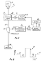
- Fig. 1 is a block diagram illustrating one form of infusion system constructed in accordance with the teachings of this invention.
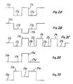
- Figs. 2-2E are plots of volume delivered by the infusion device versus time illustrating different examples of test pulses.
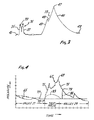
- Fig. 3 is a plot showing one pressure wave response indicative of the fluid being properly supplied to the vessel of a patient and a second pressure wave response indicative of infiltration.
- Fig. 4 is a plot showing the relationship of the pressure response to the infustion rate for infiltration conditions and normal conditions.
- Fig. 5 is a flow chart showing how the system functions to detect infiltration.
- Fig. 1 shows an infusion system 11 which comprises a source 13 of a parenteral fluid, an infusion device 15 for delivering the parenteral fluid through conduit means 17 to a patient.
- the conduit means 17 may comprise flexible tubing or other flow channels for supplying the parenteral fluid to the patient.
- the conduit means terminates in a needle 18, such as an I.V. needle, which is adapted to be inserted into a vessel of the patient's vascular system so that the open distal end of the needle communicates with the interior of the vessel.
- the needle 18 is inserted into a vein. If the open distal end of the needle communicates with tissue, as when the needle is forced completely through the vessel wall, infiltration has occurred.
- the infusion device 15 may be any infusion device which is controllable to produce a test pulse 19 (Fig. 2) and, as such, may include an infusion pump, a controller, syringe or the like.
- the infusion device 15 includes a motor, such as a stepping motor 21, for driving the pump and pump controls 22 for controlling the motor.
- the pump 20 is a positive displacement pump, and accordingly, its output can be controlled by controlling the speed of the motor 21.
- the pump controls 22 control the motor speed as described more fully hereinbelow to provide the infusion device with the desired output.
- the infusion device 15 is a peristaltic pump of the type disclosed in Application Serial No. 661,032 entitled Continuous Delivery Peristaltic Pump and filed on October 15, 1984.
- Such an infusion pump has a normal delivery pattern 25 which, in this example, is essentially constant as shown by the flat portions of the pump delivery curve of Fig. 2. This is the result of accelerating through the deadband of the peristaltic pump.
- the curve of Fig. 2 is somewhat idealized in that the preferred infusion pump provides periodic short spikes and valleys of exceedingly short duration; however, these are sufficiently insignificant so that the normal delivery patter of the pump can be considered as essentially constant, although a constant flow rate during the normal delivery pattern is not required.
- the pump controls 22 periodically, and/or on demand, increase the speed of the stepping motor 21 to cause the infusion pump 20 to provide the test pulse 19 which, in the illustrated embodiment of Fig. 2, is in the form of an essentially square wave having a duration of approximately four seconds.
- the infusion rate, and hence the volume delivered, during the test pulse preferably varies with the selected infusion rate for the infusion device 15.
- the duration of the test pulse 19 may be constant for all selected infusion rates. Selection of the infusion rate also results in selection of the associated flow rate for the test pulse 19.
- the pump controls 22, as is common for infusion devices of this type are programmable to enable the attendant to select or punch in a desired or selected infusion rate.
- the pump controls 22 reduce the speed of the stepping motor 21 just before and just after each test pulse 19 to cause the infusion pump 20 to provide separating regions, which in this embodiment, are leading and trailing infusion valleys 27 and 29, respectively, contiguous to, and on opposite sides of, the test pulse 19.
- the valleys 27 and 29 are square waves of short duration during which the infusion rate is reduced sufficiently to wholly or partially compensate for the increased infusion rate which takes place during the test pulse 19.
- the valleys 27 and 29 reduce the total flow by the same amount that the test pulse increases it so that the average or net effect across the valleys 27 and 29 and the test pulse 19 is an infusion rate equal to the rate represented by the normal delivery pattern 25.
- each of the valleys 27 and 29 may have a duration which is twice as long as the duration of the test pulse 19, with such duration being 8 seconds in this embodiment and constant for all selected infusion rates.
- the test pulse 19 and the valleys 27 and 29 constitute an altered pattern of flow.
- Test pulses can be provided in various different ways, and additional examples of test pulses, which can be distinguished from the normal delivery pattern, are shown in Figs. 2A-2E. Portions of the curves shown in Figs. 2A-2E corresponding to portions of the curve shown in Fig. 2 are designated by corresponding reference numerals followed by the letter "a”, "b”, “c”, “d”, and "e”, respectively.
- the test pulse 19a is separated from the normal delivery pattern 25a by leading and trailing valleys 27a and 29a in much the same manner as disclosed in Fig. 2.
- the infusion rate during the test pulse 19a is the same as the infusion rate during the normal delivery pattern 25a.
- the infusion rates during the valleys 27a and 29a can be "0" or negative, preferably, the infusion rates during these times are positive.
- the infusion rates during the valleys 27a and 29a can be different, preferably, they are essentially the same.
- test pulse 19b is negative, i.e., the infusion pump 20 is reversed to create the infusion pulse.
- the infusion rate during the valleys 27b and 29b may be either positive or negative, in this embodiment, they are essentially "0.”
- a plurality of test pulses 19c is provided in relatively rapid succession before the infusion rate returns to the normal delivery pattern 25c.
- the valleys 27c and 29c between adjacent test pulses 19c constitute both trailing and leading valleys as shown.
- the separating regions 27d and 29d are not distinguishable from the normal delivery pattern 25d, and so the altered pattern of delivery consists only of the test pulse 19d. This can be contrasted with the embodiments described above in which the altered pattern comprises both the leading and trailing separating regions and the test pulses.
- the separating regions 27e and 29e represent periods during which the flow rate is greater than during the normal delivery pattern 25e, and the test pulse 19e represents a decreased flow rate which may be equal to, greater than or less than the flow rate during the normal delivery pattern. As illustrated, the flow rate during the test pulse 19e is greater than the flow rate during the normal delivery pattern 25e.
- test pulses of the type shown in Figs. 2B and 2E, which have flow rates less than the adjacent separating regions are not preferred.
- Fig. 3 shows examples of pressure wave responses 31 and 33 which indicate in-the-vessel and infiltration conditions, respectively. Although the pressure wave responses 31 and 33 are both shown in Fig. 3, they are not in scale in relation to each other. In reality, Fig. 3 shows curves which represent the pressure wave responses, but the curves, if desired, can be considered as the pressure wave responses.
- the pressure provided by the pressure wave response 31 rises rapidly and almost instantaneously along a rising edge 35 and decays at about the same rate as represented by a falling edge 37. In between the edges 35 and 37, the pressure remains approximately constant, except for a short duration valley 39 which is representative of the deadband of the peristaltic pump being employed.
- the pressure wave response 31 was generated by a peristaltic pump having a deadband and operating at about 350 cc's per hour, which is a high-delivery rate. If a peristaltic pump which accelerates through the deadband were employed, the duration and magnitude of the valley 39 would be greatly reduced.
- the pressure wave response 31 is essentially a square wave if the valley 39 is ignored. With the open distal end of the needle 18 of the conduit means 17 properly communicating with the interior of the vessel of the patient's cardiovascular system, the pressure wave response 31 is simply the result of forcing the additional fluid into the fluid carried by the vessel. For example, for an infusion rate of 5 cc/hour, the pressure wave response 31 may rise about 5 mm Hg above a base line.
- the pressure wave response 33 is created in the conduit means 17. Specifically, the pressure wave response 33 rises along a rising edge or leading portion 43 and falls along a falling edge or trailing portion 45 with both the rise time and fall time being much greater than for the pressure wave response 31.
- the pressure wave response 33 has a maximum pressure or peak value 47 which is much higher than the maximum pressure or peak value of the pressure wave response 31. For example, for an infusion rate of 5 cc/hour, the pressure wave response 33 may rise about 20 mm Hg above a baseline 49.
- the rising edge has a discontinuity 48 which is the result of using a peristaltic infusion pump to generate the pressure wave response 33 which did not accelerate through the deadband and, therefore, did not have an essentially constant delivery rate.
- the pressure, or pressure response, of the parenteral fluid in the conduit means 17 can be monitored in various different ways, such as by a pressure transducer 51 which provides an electronic analog pressure signal which is related to the pressure in the conduit means 17.
- the pressure signal from the transducer 51 is amplified by an amplifier 53, conditioned in signal conditioning circuitry 55 and sampled in an analog-to-digital converter (A/D converter) 57 which provides the samples to a microprocessor 59.
- the signal conditioning circuitry 55 is conventional and is provided for the purpose of adjusting or compensating for various variables, such as temperature. Of course, if these variables are not considered significant, the signal conditioning circuitry 55 can be eliminated.
- the samples of the pressure signal from the transducer 51 may be taken continuously or taken only during the sample time.
- the microprocessor 59 is used to separate the samples taken during the sample time from those which are not.
- the A/D converter 57 samples the pressure signal continuously and provides the samples in a digital format to the microprocessor 59.
- the sampling frequency of the A/D converter 57 is preferably higher than the sampling frequency required for detecting infiltration or other abnormal infusion. For example, if infiltration detection requires about one sample per second, samples may be taken at, for example, 5 samples per second, 40 samples per second, etc. The samples can then be combined in any of a variety of ways to produce an overall sample value for each second by the microprocessor 59. In any event, the microprocessor 59 performs an integration function as described below to determine if infiltration has occurred.
- Fig. 4 shows a pressure response 65 in the conduit 17 as measured by the transducer 51 in response to infusion of fluid through the conduit to the patient.
- the pressure generally diminishes during the valley 27 until the leading edge of test pulse 19, at which time a pressure wave response 67 is initiated.
- the response 67 is indicative of abnormal infusion, e.g., infiltration.
- the pressure wave response 67 rises, with modest interruption to a peak value 69 of pressure which is reached at approximately the end of the test pulse 19.
- the pressure then slowly decays during the valley 29, again with modest interruption, to the end of the valley 29.
- the pressure wave response 67 has a leading portion 71 that extends from an initial point 73 at the beginning of the test pulse 19 to the peak value 69 and a trailing portion 75 that extends from the peak value 69 to a baseline 77.
- the baseline 77 is established by the microprocessor 59 as a function of the pressure response 65 intermediate test pulses 19. More specifically, the baseline 77 is established by suitably smoothing the pressure response 65 between test pulses 19, and this function can be carried out by the microprocessor. Accordingly, the baseline 77 lags the pressure response 65. However, at the initiation of the test pulse 19, the baseline 77 then existing is frozen by the microprocessor such that it remains essentially constant throughout at least the test pulse 19 and the trailing valley 29.
- the pressure samples from the A/D converter 57 are slew-rate limited and averaged to provide pressure values for updating the baseline 77.
- the A/D converter 57 may provide 40 pressure samples per second, and the slew-rate limiting processing limits each sample to a value which is no greater than 1.25 times, and no less than 0.75 times, the value of the previous sample. Following this, a 1/4 second average of ten of the samples is taken, and this average value provides a new point for updating the baseline 77.
- four new smoothed pressure readings are provided each second.
- the baseline 77 is then typically derived by passing these samples through an additional smoothing process, such as a single-pole low-pass filter with a time constant of about 2 seconds.
- a primary advantage of slew-rate limiting is to eliminate spurious spikes that may occur in the pressure response 65 that might be incorrectly interpreted as the peak value 69.
- slew-rate limiting and averaging provides a desired smoothing effect for the baseline 77 to reduce transient irregularities that might otherwise occur in the baseline 77.
- the area between the pressure wave response 67 and the baseline 77 is calculated by the microprocessor between the initial point 73 and a truncation point 79.
- the truncation point 79 is the time at which the pressure on the trailing portion 75 drops to 50 percent of the peak value 69. More generally, the truncation point 79 is the first to occur of a pre-established percent of the peak value 69 and the end of the trailing valley 29. Because in the example of Fig. 4, the predetermined percent of the peak value 69 occurred first, the integration is truncated at this point along a line 81.
- the integration of the pressure wave response 67 may proceed from the initial point 73 to the peak value 69 to provide a front end area.
- This front end area may be used in lieu of, or in addition to, the truncated area, i.e., the area obtained from integrating from the initial point 73 to the truncation point 79, to determine whether or not infiltration has occurred.
- Fig. 4 also shows a somewhat idealized pressure wave response 83 in dashed lines which is indicative of the proper supply of fluid to the patient.
- the pressure wave responses 67 and 83 would, of course, not exist simultaneously, but they are shown together for comparative purposes. Applying the same criteria for integration of the pressure wave response 83, virtually the entire area between the pressure wave response 83 and the baseline 77 would be determined. However this area is much less than the area obtained by the truncated integration of the pressure wave response 67. Accordingly, the microprocessor 59 can readily determine whether or not infiltration has occurred.
- the area information can be used in various different ways to arrive at a decision regarding the presence or absence of infiltration or other abnormal infusion.
- both the truncated area and the front end area may be normalized and compared with known thresholds, and an alarm condition may be declared in response to one or more of these areas exceeding the established threshold.
- an alarm condition is not declared until three consecutive normalized truncated areas or three consecutive normalized front end areas resulting from three consecutive test pulses have exceeded their respective thresholds.
- the truncated area is normalized by dividing it by a divisor which is a function of the difference between the infusion rate during the test pulse and the infusion rate during either of the valleys 27 and 29.
- the function is simply the difference between these infusion rates.
- the quotient or normalized area is then compared with a known threshold.
- the front end area is normalized in the same way and compared with its threshold.
- the threshold varies with a number of factors, the most important of which is the gauge or size of the needle 18.
- the areas can be effectively normalized for needle (or other cannula) size by employing different thresholds for different ranges of needle size. Examples of suitable thresholds for both truncated area and front end area as a function of needle gauge are shown in the table below: Thus, if a 16-gauge needle is used, an alarm condition indicative of abnormal infusion would be declared if any three-consecutive test pulses yielded a normalized truncated area of greater than .2 or a normalized front end area of greater than .1.
- Another feature of the system is to ascertain if pressure conditions in the conduit means 17 are suitable for detecting if fluid is being improperly supplied by the conduit means to the patient.
- this feature of the system is particularly adapted for use with the integration technique of this invention, its use is not so limited, and it can be used with other techniques for determining whether or not abnormal infusion exists.
- the suitability of the pressure conditions in the conduit means 17 can be evaluated in various different ways to determine if these conditions are suitable for detecting abnormal infusion. This can be accomplished, for example, by comparing a function of the pressure of the fluid in the conduit means 17 during the normal delivery pattern 25 to a threshold.
- the function of the pressure of the fluid in the conduit means 17 can be the raw pressure samples from the A/D converter 57 per se, preferably this function includes some form of smoothing.
- BQI B1 + K(B2)
- BQI is a baseline quality index
- B1 is the magnitude of the baseline 77 prior to the valley 27
- K is a constant which may be, for example, 3
- B2 is the rms value of a plurality, such as 120, of baseline 77 magnitudes occurring just prior to the baseline magnitude representing B1.
- BQI is a function of the pressure in the conduit means 17. Assuming that the pressure response 65 is slew-rate limited, averaged and low-pass filtered to determine the baseline 77 as described above, then B1 is the last baseline 77 value prior to the valley 27, and B2 is the rms value of 120 baseline values immediately preceding the value used for determining B1.
- Fig. 5 is a flow chart showing the basic steps in the truncated integration process used by the system to detect infiltration.
- a new BQI calculation commences using the BQI equation set forth above.
- the time for the next site check i.e., the time to initiate the altered infusion pattern represented by the valley 27, the test pulse 19, and the valley 29 occurs, it is allowed to proceed only if the BQI is below the threshold magnitude as described above.
- the next site check referred to in Fig. 5 may be manually initiated by entering information into the infusion device 15 or in response to programming of the infusion device 15 to provide site checks at specified times or at specified intervals.
- the infusion device 15, and in particular, the infusion pump 20 will provide the reduced infusion represented by the valley 27 only if the BQI is below the specified threshold.
- the baseline 77 is frozen and integration of the difference between the baseline and the pressure wave response commences as shown in Fig. 5.
- the integration continues from the initial point 73 beyond the end of the test pulse 19 until the first to occur of a pressure less than 50 percent of the peak value 69 or the end of the trailing valley 29.
- the truncated area and the front end areas are normalized for infusion rate and needle-size effects as described above.
- the microprocessor 59 makes a decision concerning abnormal infusion as described above, and if infusion is abnormal, the alarm 63 is energized and/or infusion is terminated.
- the microprocessor may require information from multiple site checks before declaring abnormal infusion.
- the abnormal infusion may be the result of any condition, such as infiltration, occlusion of the conduit means 17, clotting or phlebitis, which leads to the creation of the pressure wave response 67 (Fig. 4).
- an attendant can determine the particular cause and seek to remedy it.
Description
- It is often necessary or desirable to infuse a flowable material or fluid, which may be liquid, a gas or a combination thereof, into a patient. One example is the administration of parenteral fluids to a patient.
- A typical infusion system includes an infusion device for delivering the fluid and conduit means for conducting the flowable material from the infusion device to the patient. The conduit means typically comprises flexible tubing leading from the infusion device and a cannula, such as a needle or catheter, for insertion into the vascular system of the patient. In normal operation, the infusion device delivers the fluid through the tubing and the needle to the vascular system of the patient.
- One problem with infusion systems of this type is a condition known as infiltration. Infiltration is a condition in which infused fluid finds its way into extravascular tissues rather than simply being released into the blood stream. Such a situation occurs when the needle is not in communication with the interior of the vessel into which the fluid is to be infused. When this occurs, fluid is infused into the interstitial spaces between layers of tissues. Thus, the patient is deprived of proper intravenous drug administration and is further subjected to possible toxic or caustic effects associated with infused fluids being in direct contact with body tissues.
- Infiltration is not the only possible type of anomaly associated with intravenous therapy which can cause the fluid to be improperly supplied to the patient. Other conditions which can cause abnormal infusion, i.e., the fluid to be improperly supplied to the patient, include venous inflamation and swelling at the infusion site (phlebitis), clotting and a wide variety of obstructions of the conduit means, such as kinking of the tubing which supplies the fluid to the patient. Many of these affect fluid flow characteristics in a manner similar to infiltration and can, therefore, be detected by infiltration detection devices.
- The goal of an infiltration detection system is to identify an abnormal infusion as early as possible without generating an excessive number of false alarms. Early detection allows the attending medical staff to rectify the problem before significant damage has been done by the infiltration and before the patient has been deprived of a significant amount of the intravenous therapy. On the other hand, if the detection system is too sensitive, false alarms will result. This is very undesirable since, from a clinical perspective, establishing a new intravenous site can be difficult and time consuming. During the time necessary to start the new IV, which can be hours in some cases, the patient is not receiving the desired treatment.
- Bobo U.S. Patent No. 4,648,869 discloses a significant advance in the field of infiltration detection systems and methods. According to the Bobo patent, an infusion system infuses a test pulse of fluid to a patient. The test pulse creates a pressure wave response which can be monitored and used to detect if abnormal infusion has occured. Such a system is also known from EP-A-0 248 633. Thus document describes an apparatus for determining if fluid is being properly supplied through a fluid delivery system to a patient, in accordance with the pre-characterization clause of Claim 1.
- Butterfield U.S. Patent No. 4,710,163 discloses an infiltration detection system which uses the test pulse-pressure wave response concept of the Bobo patent. However, the Butterfield system compares the pressure wave response with a reference pressure wave response which represents the normal response when there is no infiltration. Specifically, the area between two curves representing these responses is used to attempt to detect infiltration. Thus, the Butterfield approach has the disadvantage of requiring that a normal pressure wave response be first determined and then stored for later comparison.
- The present invention provides an apparatus for determining if fluid is being properly supplied through a delivery system to a patient, said apparatus comprising means for delivering fluid through the delivery system so as to create pressure wave responses in the delivery system; detection means for detecting the pressure of the fluid in the system; control means responsive to the detected pressure and operable to determine an area under at least a portion of a pressure versus time curve, and including means responsive to the magnitude of the area to determine if the fluid is being improperly supplied by the fluid delivery system to the patient, characterised by means for establishing a baseline as a function of the pressure in the delivery system when the pressure wave responses are not present, and in that said area is determined be.tween the baseline and said pressure versus time curve.
- By use of the present invention, it is not necessary to first establish a normal pressure wave response for a patient, now is it necessary to compare this assumed normal response to the pressure wave response.
Rather, all that is required to make accurate determinations as to the proper supply of fluid to a patient is appropriate area information from the pressure wave response. - The means for delivering fluid through the delivery system so as to create a pressure wave response in the delivery system may be accomplished, for example, in accordance with the teachings of Bobo U.S. Patent No. 4,648,869. Thus, as disclosed in the Bobo patent, the fluid may be delivered in both a normal delivery pattern and a test pulse, with the test pulse creating a pressure wave response in the delivery system.
- The pressure wave response may have a peak value of pressure and a leading portion and a trailing portion on opposite sides of the peak value. When fluid is being properly supplied to the patient, the pressure will rise rapidly but typically not to a very high peak value. However, if the fluid is being improperly supplied to the patient as when infiltration occurs, the pressure will rise to a higher peak value over a longer period of time. The peak pressure is large because the infused fluid has no immediate means of escape from the interstitial spaces. After termination of the test pulse, the pressure will drop rapidly to its nominal level if the fluid is being properly supplied to the patient. In the case of abnormal infusion, the pressure drops much more slowly from the peak value because there is no immediate escape path for the fluid.
- The invention determines an area characteristic of the pressure wave response to determine if fluid is being improperly supplied to the patient. The function integrated is the difference between a baseline and a curve representing the pressure wave response and extends along the curve from an initial point to a truncation point. The baseline is established as a function of the pressure in the delivery system when the test pulse and, hence the pressure wave response, are not present. The baseline used for the integration is preferably held essentially constant during the integration.
- The truncation point, or upper limit on the integration, preferably is on the trailing portion of the curve corresponding to the trailing portion of the pressure wave response, i.e., it preferably occurs after the peak value of pressure has been attained. Although it is possible to truncate the integration prior to or at the peak value of pressure, because the peak pressure is typically drastically different when the fluid is being improperly supplied to the patient, it is highly desirable to include, and go beyond, the peak value for the integration.
- The output from an infusion pump used to deliver the fluid to the patient may not be totally uniform, and preferably, the truncation point occurs at a time which is sufficiently beyond the peak value of pressure so as to take this into account. Typically, it is preferred that the truncation point be at a time at which the pressure is no greater than about 70 percent of the peak value.
- On the other hand, the truncation point is preferably essentially outside of the noise range, and this typically means that it occurs at a time at which the pressure is no less than about 30 percent of the peak value. Thus, the truncation point is preferably at a time at which the pressure is between about 30 and about 70 percent of the peak value with about 50 percent being considered optimum. The initial point, or lower limit on the integration, is preferably essentially at the beginning of the point on the curve corresponding to the beginning of the pressure wave response.
- Alternatively, or in addition thereto, the integration of the pressure wave response may extend from the initial point to about the peak value of pressure. Such an integration would determine a front end area. The detecting means may be responsive to either or both of the front end area and the truncated area, i.e., the area established by integrating the pressure wave response from the initial point to the truncation point. Preferably, the detecting means is responsive to both of these areas.
- The infusion device should be capable of delivering the fluid in a test pulse. Broadly, it is only necessary that the test pulse be capable of creating a pressure wave response in the delivery system. Typically, to accomplish this, the test pulse must be distinguishable from the normal deliver pattern.
- The test pulse can be distinguished from the normal delivery pattern in different ways. For example, the test pulse can be separated from the normal delivery pattern by separating regions on one or both sides of the test pulse, with each of the separating regions providing a different flow rate of fluid than the adjacent portions of the test pulse. In a broad sense, the separating regions may have flow rates equal to the flow rate of the normal delivery pattern. Preferably, however, the infusion device is capable of delivering the fluid in an altered pattern which includes a test pulse and leading and trailing valleys on opposite sides of the test pulse. The test pulse provides a greater flow rate of fluid than the normal delivery pattern, and each of the valleys provides a lesser flow rate of fluid than the adjacent portions of the normal delivery pattern. When this form of infusion is used, the truncation point is preferably established as the first to occur of a specified percent of peak value and the termination of the trailing valley. This is desirable because, in the case of infiltration, where the pressure wave response decays slowly, the predetermined percent of peak value may not be reached. With this form of infusion, the initial point may coincide with the beginning of the test pulse.
- The flow rate during the test pulse may be less than, greater than, or equal to the flow rate during the normal delivery pattern. However, the preferred altered pattern, as described above, has several advantages, including the advantage of preventing the test pulse from significantly altering the average flow of fluid to the patient. It is also possible to reverse the flow in the delivery system to create the test pulse. However, this is not preferred because it may cause the patient's vessel to collapse around the needle.
- The area information from the test pulse can be processed in various different ways to determine if the fluid is being properly or improperly supplied to the patient. Generally, a larger area indicates an alarm condition, and a smaller area is indicative of normal infusion. The areas are also a function of test pulse infusion rates. Of course, information from multiple pressure wave responses derived from multiple test pulses can be processed to gain greater assurance that the infusion system is being correctly monitored.
- The invention, together with additional features and advantages thereof, may best be understood by reference to the following description taken in connection with the accompanying illustrative drawing.
- Fig. 1 is a block diagram illustrating one form of infusion system constructed in accordance with the teachings of this invention.
- Figs. 2-2E are plots of volume delivered by the infusion device versus time illustrating different examples of test pulses.
- Fig. 3 is a plot showing one pressure wave response indicative of the fluid being properly supplied to the vessel of a patient and a second pressure wave response indicative of infiltration.
- Fig. 4 is a plot showing the relationship of the pressure response to the infustion rate for infiltration conditions and normal conditions.
- Fig. 5 is a flow chart showing how the system functions to detect infiltration.
- Fig. 1 shows an
infusion system 11 which comprises asource 13 of a parenteral fluid, aninfusion device 15 for delivering the parenteral fluid through conduit means 17 to a patient. The conduit means 17 may comprise flexible tubing or other flow channels for supplying the parenteral fluid to the patient. The conduit means terminates in aneedle 18, such as an I.V. needle, which is adapted to be inserted into a vessel of the patient's vascular system so that the open distal end of the needle communicates with the interior of the vessel. In this embodiment, theneedle 18 is inserted into a vein. If the open distal end of the needle communicates with tissue, as when the needle is forced completely through the vessel wall, infiltration has occurred. - The
infusion device 15 may be any infusion device which is controllable to produce a test pulse 19 (Fig. 2) and, as such, may include an infusion pump, a controller, syringe or the like. In this embodiment, theinfusion device 15 includes a motor, such as a steppingmotor 21, for driving the pump and pump controls 22 for controlling the motor. Thepump 20 is a positive displacement pump, and accordingly, its output can be controlled by controlling the speed of themotor 21. The pump controls 22 control the motor speed as described more fully hereinbelow to provide the infusion device with the desired output. - In a preferred construction, the
infusion device 15 is a peristaltic pump of the type disclosed in Application Serial No. 661,032 entitled Continuous Delivery Peristaltic Pump and filed on October 15, 1984. Such an infusion pump has anormal delivery pattern 25 which, in this example, is essentially constant as shown by the flat portions of the pump delivery curve of Fig. 2. This is the result of accelerating through the deadband of the peristaltic pump. The curve of Fig. 2 is somewhat idealized in that the preferred infusion pump provides periodic short spikes and valleys of exceedingly short duration; however, these are sufficiently insignificant so that the normal delivery patter of the pump can be considered as essentially constant, although a constant flow rate during the normal delivery pattern is not required. - The pump controls 22 periodically, and/or on demand, increase the speed of the stepping
motor 21 to cause theinfusion pump 20 to provide thetest pulse 19 which, in the illustrated embodiment of Fig. 2, is in the form of an essentially square wave having a duration of approximately four seconds. As described more fully in Bobo Patent No. 4,648,869 the infusion rate, and hence the volume delivered, during the test pulse preferably varies with the selected infusion rate for theinfusion device 15. However, the duration of thetest pulse 19 may be constant for all selected infusion rates. Selection of the infusion rate also results in selection of the associated flow rate for thetest pulse 19. In this regard, the pump controls 22, as is common for infusion devices of this type, are programmable to enable the attendant to select or punch in a desired or selected infusion rate. - The pump controls 22 reduce the speed of the stepping
motor 21 just before and just after eachtest pulse 19 to cause theinfusion pump 20 to provide separating regions, which in this embodiment, are leading and trailinginfusion valleys test pulse 19. Thevalleys test pulse 19. Preferably, thevalleys valleys test pulse 19 is an infusion rate equal to the rate represented by thenormal delivery pattern 25. For example, each of thevalleys test pulse 19, with such duration being 8 seconds in this embodiment and constant for all selected infusion rates. Thetest pulse 19 and thevalleys - Test pulses can be provided in various different ways, and additional examples of test pulses, which can be distinguished from the normal delivery pattern, are shown in Figs. 2A-2E. Portions of the curves shown in Figs. 2A-2E corresponding to portions of the curve shown in Fig. 2 are designated by corresponding reference numerals followed by the letter "a", "b", "c", "d", and "e", respectively.
- In Fig. 2A, the test pulse 19a is separated from the
normal delivery pattern 25a by leading and trailing valleys 27a and 29a in much the same manner as disclosed in Fig. 2. However, the infusion rate during the test pulse 19a is the same as the infusion rate during thenormal delivery pattern 25a. Although the infusion rates during the valleys 27a and 29a can be "0" or negative, preferably, the infusion rates during these times are positive. Also, although the infusion rates during the valleys 27a and 29a can be different, preferably, they are essentially the same. - In Fig. 2B, the
test pulse 19b is negative, i.e., theinfusion pump 20 is reversed to create the infusion pulse. Although the infusion rate during the valleys 27b and 29b may be either positive or negative, in this embodiment, they are essentially "0." - In Fig. 2C, a plurality of
test pulses 19c is provided in relatively rapid succession before the infusion rate returns to the normal delivery pattern 25c. In this event, thevalleys 27c and 29c betweenadjacent test pulses 19c constitute both trailing and leading valleys as shown. - In Fig. 2D, the separating
regions normal delivery pattern 25d, and so the altered pattern of delivery consists only of thetest pulse 19d. This can be contrasted with the embodiments described above in which the altered pattern comprises both the leading and trailing separating regions and the test pulses. - In Fig. 2E, the separating
regions normal delivery pattern 25e, and thetest pulse 19e represents a decreased flow rate which may be equal to, greater than or less than the flow rate during the normal delivery pattern. As illustrated, the flow rate during thetest pulse 19e is greater than the flow rate during thenormal delivery pattern 25e. Generally, test pulses of the type shown in Figs. 2B and 2E, which have flow rates less than the adjacent separating regions, are not preferred. - The presence of the
test pulse 19 in the conduit means 17 creates a pressure wave response which has different characteristics depending upon whether or not the flowable material is being improperly supplied by the conduit means 17 to the patient. Fig. 3 shows examples ofpressure wave responses 31 and 33 which indicate in-the-vessel and infiltration conditions, respectively. Although thepressure wave responses 31 and 33 are both shown in Fig. 3, they are not in scale in relation to each other. In reality, Fig. 3 shows curves which represent the pressure wave responses, but the curves, if desired, can be considered as the pressure wave responses. - The pressure provided by the
pressure wave response 31 rises rapidly and almost instantaneously along a risingedge 35 and decays at about the same rate as represented by a fallingedge 37. In between theedges short duration valley 39 which is representative of the deadband of the peristaltic pump being employed. In this regard, thepressure wave response 31 was generated by a peristaltic pump having a deadband and operating at about 350 cc's per hour, which is a high-delivery rate. If a peristaltic pump which accelerates through the deadband were employed, the duration and magnitude of thevalley 39 would be greatly reduced. For this reason, it is preferred to utilize a peristaltic pump which does accelerate through the deadband so that anyvalley 39 would be of substantially less magnitude and duration than illustrated in Fig. 3. However, thepressure wave response 31 is essentially a square wave if thevalley 39 is ignored. With the open distal end of theneedle 18 of the conduit means 17 properly communicating with the interior of the vessel of the patient's cardiovascular system, thepressure wave response 31 is simply the result of forcing the additional fluid into the fluid carried by the vessel. For example, for an infusion rate of 5 cc/hour, thepressure wave response 31 may rise about 5 mm Hg above a base line. - When infiltration occurs, the open distal end of the
needle 18 is out of the interior of the vessel and communicates with tissue. As a result, the pressure wave response 33 is created in the conduit means 17. Specifically, the pressure wave response 33 rises along a rising edge or leadingportion 43 and falls along a falling edge or trailingportion 45 with both the rise time and fall time being much greater than for thepressure wave response 31. In addition, the pressure wave response 33 has a maximum pressure orpeak value 47 which is much higher than the maximum pressure or peak value of thepressure wave response 31. For example, for an infusion rate of 5 cc/hour, the pressure wave response 33 may rise about 20 mm Hg above a baseline 49. The rising edge has a discontinuity 48 which is the result of using a peristaltic infusion pump to generate the pressure wave response 33 which did not accelerate through the deadband and, therefore, did not have an essentially constant delivery rate. - The pressure, or pressure response, of the parenteral fluid in the conduit means 17 can be monitored in various different ways, such as by a pressure transducer 51 which provides an electronic analog pressure signal which is related to the pressure in the conduit means 17. In this embodiment, the pressure signal from the transducer 51 is amplified by an amplifier 53, conditioned in signal conditioning circuitry 55 and sampled in an analog-to-digital converter (A/D converter) 57 which provides the samples to a
microprocessor 59. The signal conditioning circuitry 55 is conventional and is provided for the purpose of adjusting or compensating for various variables, such as temperature. Of course, if these variables are not considered significant, the signal conditioning circuitry 55 can be eliminated. - The samples of the pressure signal from the transducer 51 may be taken continuously or taken only during the sample time. In the former case, the
microprocessor 59 is used to separate the samples taken during the sample time from those which are not. However, in this embodiment, the A/D converter 57 samples the pressure signal continuously and provides the samples in a digital format to themicroprocessor 59. - The sampling frequency of the A/
D converter 57 is preferably higher than the sampling frequency required for detecting infiltration or other abnormal infusion. For example, if infiltration detection requires about one sample per second, samples may be taken at, for example, 5 samples per second, 40 samples per second, etc. The samples can then be combined in any of a variety of ways to produce an overall sample value for each second by themicroprocessor 59. In any event, themicroprocessor 59 performs an integration function as described below to determine if infiltration has occurred. - Fig. 4 shows a
pressure response 65 in theconduit 17 as measured by the transducer 51 in response to infusion of fluid through the conduit to the patient. As shown, the pressure generally diminishes during thevalley 27 until the leading edge oftest pulse 19, at which time apressure wave response 67 is initiated. Theresponse 67 is indicative of abnormal infusion, e.g., infiltration. Thepressure wave response 67 rises, with modest interruption to a peak value 69 of pressure which is reached at approximately the end of thetest pulse 19. The pressure then slowly decays during thevalley 29, again with modest interruption, to the end of thevalley 29. Thus, thepressure wave response 67 has a leading portion 71 that extends from aninitial point 73 at the beginning of thetest pulse 19 to the peak value 69 and a trailingportion 75 that extends from the peak value 69 to a baseline 77. - The baseline 77 is established by the
microprocessor 59 as a function of thepressure response 65intermediate test pulses 19. More specifically, the baseline 77 is established by suitably smoothing thepressure response 65 betweentest pulses 19, and this function can be carried out by the microprocessor. Accordingly, the baseline 77 lags thepressure response 65. However, at the initiation of thetest pulse 19, the baseline 77 then existing is frozen by the microprocessor such that it remains essentially constant throughout at least thetest pulse 19 and the trailingvalley 29. - Various different techniques can be used to smooth the
pressure response 65 betweentest pulses 19. According to one preferred smoothing technique, the pressure samples from the A/D converter 57 are slew-rate limited and averaged to provide pressure values for updating the baseline 77. By way of illustration and not by way of limitation, the A/D converter 57 may provide 40 pressure samples per second, and the slew-rate limiting processing limits each sample to a value which is no greater than 1.25 times, and no less than 0.75 times, the value of the previous sample. Following this, a 1/4 second average of ten of the samples is taken, and this average value provides a new point for updating the baseline 77. With this technique, four new smoothed pressure readings are provided each second. The baseline 77 is then typically derived by passing these samples through an additional smoothing process, such as a single-pole low-pass filter with a time constant of about 2 seconds. - A primary advantage of slew-rate limiting is to eliminate spurious spikes that may occur in the
pressure response 65 that might be incorrectly interpreted as the peak value 69. In addition, slew-rate limiting and averaging provides a desired smoothing effect for the baseline 77 to reduce transient irregularities that might otherwise occur in the baseline 77. - To determine if infiltration or other abnormal infusion has occurred, the area between the
pressure wave response 67 and the baseline 77 is calculated by the microprocessor between theinitial point 73 and atruncation point 79. In this embodiment, thetruncation point 79 is the time at which the pressure on the trailingportion 75 drops to 50 percent of the peak value 69. More generally, thetruncation point 79 is the first to occur of a pre-established percent of the peak value 69 and the end of the trailingvalley 29. Because in the example of Fig. 4, the predetermined percent of the peak value 69 occurred first, the integration is truncated at this point along aline 81. - Alternatively, or in addition thereto, the integration of the
pressure wave response 67 may proceed from theinitial point 73 to the peak value 69 to provide a front end area. This front end area may be used in lieu of, or in addition to, the truncated area, i.e., the area obtained from integrating from theinitial point 73 to thetruncation point 79, to determine whether or not infiltration has occurred. - Fig. 4 also shows a somewhat idealized
pressure wave response 83 in dashed lines which is indicative of the proper supply of fluid to the patient. Thepressure wave responses pressure wave response 83, virtually the entire area between thepressure wave response 83 and the baseline 77 would be determined. However this area is much less than the area obtained by the truncated integration of thepressure wave response 67. Accordingly, themicroprocessor 59 can readily determine whether or not infiltration has occurred. - The area information can be used in various different ways to arrive at a decision regarding the presence or absence of infiltration or other abnormal infusion. For example, both the truncated area and the front end area may be normalized and compared with known thresholds, and an alarm condition may be declared in response to one or more of these areas exceeding the established threshold. In a preferred decision-making technique, an alarm condition is not declared until three consecutive normalized truncated areas or three consecutive normalized front end areas resulting from three consecutive test pulses have exceeded their respective thresholds. More specifically, in one technique, the truncated area is normalized by dividing it by a divisor which is a function of the difference between the infusion rate during the test pulse and the infusion rate during either of the
valleys - It has been found that the threshold varies with a number of factors, the most important of which is the gauge or size of the
needle 18. The areas can be effectively normalized for needle (or other cannula) size by employing different thresholds for different ranges of needle size. Examples of suitable thresholds for both truncated area and front end area as a function of needle gauge are shown in the table below:
Thus, if a 16-gauge needle is used, an alarm condition indicative of abnormal infusion would be declared if any three-consecutive test pulses yielded a normalized truncated area of greater than .2 or a normalized front end area of greater than .1. - In the above table, it is assumed that the units on the area of pressure wave response are mmHg-seconds and that the infusion rates are in milliliters per hour. Of course, different units can be employed, and the thresholds adjusted accordingly.
- Another feature of the system is to ascertain if pressure conditions in the conduit means 17 are suitable for detecting if fluid is being improperly supplied by the conduit means to the patient. Although this feature of the system is particularly adapted for use with the integration technique of this invention, its use is not so limited, and it can be used with other techniques for determining whether or not abnormal infusion exists.
- The suitability of the pressure conditions in the conduit means 17 can be evaluated in various different ways to determine if these conditions are suitable for detecting abnormal infusion. This can be accomplished, for example, by comparing a function of the pressure of the fluid in the conduit means 17 during the
normal delivery pattern 25 to a threshold. Although the function of the pressure of the fluid in the conduit means 17 can be the raw pressure samples from the A/D converter 57 per se, preferably this function includes some form of smoothing. According to a preferred technique, the following equation is used:
where, BQI is a baseline quality index, B1 is the magnitude of the baseline 77 prior to thevalley 27, K is a constant which may be, for example, 3 and B2 is the rms value of a plurality, such as 120, of baseline 77 magnitudes occurring just prior to the baseline magnitude representing B1. Thus, BQI is a function of the pressure in the conduit means 17. Assuming that thepressure response 65 is slew-rate limited, averaged and low-pass filtered to determine the baseline 77 as described above, then B1 is the last baseline 77 value prior to thevalley 27, and B2 is the rms value of 120 baseline values immediately preceding the value used for determining B1. - It has been found that, if BQI as calculated using the equation set forth above exceeds a threshold, the pressure conditions in the conduit means 17 are not suitable for determining whether or not abnormal infusion exists. Although this threshold can be adjusted as desired, by way of example, a threshold of 85 mmHg is suitable for many applications.
- Fig. 5 is a flow chart showing the basic steps in the truncated integration process used by the system to detect infiltration. As shown in Fig. 5, when the end of the
valley 29 occurs, a new BQI calculation commences using the BQI equation set forth above. When the time for the next site check, i.e., the time to initiate the altered infusion pattern represented by thevalley 27, thetest pulse 19, and thevalley 29 occurs, it is allowed to proceed only if the BQI is below the threshold magnitude as described above. In this regard, the next site check referred to in Fig. 5 may be manually initiated by entering information into theinfusion device 15 or in response to programming of theinfusion device 15 to provide site checks at specified times or at specified intervals. In any event, theinfusion device 15, and in particular, theinfusion pump 20 will provide the reduced infusion represented by thevalley 27 only if the BQI is below the specified threshold. - When the end of the
valley 27 is detected, i.e., the start of thetest pulse 19, the baseline 77 is frozen and integration of the difference between the baseline and the pressure wave response commences as shown in Fig. 5. The integration continues from theinitial point 73 beyond the end of thetest pulse 19 until the first to occur of a pressure less than 50 percent of the peak value 69 or the end of the trailingvalley 29. At the end of the integration, the truncated area and the front end areas are normalized for infusion rate and needle-size effects as described above. Following this, themicroprocessor 59 makes a decision concerning abnormal infusion as described above, and if infusion is abnormal, the alarm 63 is energized and/or infusion is terminated. Of course, the microprocessor may require information from multiple site checks before declaring abnormal infusion. - The abnormal infusion may be the result of any condition, such as infiltration, occlusion of the conduit means 17, clotting or phlebitis, which leads to the creation of the pressure wave response 67 (Fig. 4). In any event, once the abnormal infusion is declared, an attendant can determine the particular cause and seek to remedy it.
- Although an exemplary embodiment of the invention has been shown and described, many changes, modifications and substitutions may be made by one having ordinary skill in the art without necessarily departing from the scope of this invention.
Claims (20)
- An apparatus for determining if fluid is being properly supplied through a delivery system to a patient, said apparatus comprising means (15) for delivering fluid through the delivery system so as to create pressure wave responses (67) in the delivery system; detection means (51) for detecting the pressure of the fluid in the system; control means responsive to the detected pressure and operable to determine an area under at least a portion of a pressure versus time curve, and including means (59) responsive to the magnitude of the area to determine if the fluid is being improperly supplied by the fluid delivery system to the patient, characterised by means (59) for establishing a baseline (77) as a function of the pressure (65) in the delivery system when the pressure wave responses (67) are not present i.e. between pressure wave responses, and in that said area is determined between the baseline (77) and said pressure versus time curve.
- An apparatus as defined in claim 1 wherein the pressure wave response (67) has a peak value (69) of pressure and a leading portion (71) and a trailing portion (75) on opposite sides of the peak value and said determining means determines the area from an initial point (73) on the leading portion (71) side of the peak value (69) to a truncation point (79) with the truncation point being on a portion of said curve corresponding to the trailing portion (75) of the pressure wave response (67).
- An apparatus as defined in claim 2 wherein said truncation point (79) is essentially outside the noise range.
- An apparatus as defined in claim 2 wherein said truncation point (79) is at a time at which the pressure is no less than 30 percent of the peak value (69).
- An apparatus as defined in claim 2 wherein said truncation point (79) is at a time at which the pressure is no greater than 70 percent of the peak value (69).
- An apparatus as defined in claim 2 wherein said truncation point (79) is at a time at which the pressure is between 30 percent to 70 percent of the peak value (69).
- An apparatus as defined in claim 2 wherein said truncation point (79) is at a time at which the pressure is about 50 percent of the peak value (69).
- An apparatus as defined in any one of claims 2 to 7 wherein the initial point (73) is essentially at the beginning of the point on said curve corresponding to the beginning of the pressure wave response (67).
- An apparatus as defined in any preceding claim including means for establishing the baseline (77) as essentially constant for the determination of said area.
- An apparatus as defined in any preceding claim including first means responsive to the pressure in the delivery system when the pressure wave response is not present to ascertain if pressure conditions in the delivery system are suitable for detecting if fluid is being improperly supplied by the delivery system to the patient.
- An apparatus as defined in claim 10 wherein said first means includes means for comparing a function of the pressure of the fluid in the conduit means during the normal delivery pattern to a threshold to ascertain if pressure conditions in the conduit means are suitable for detecting if fluid is being improperly supplied by the conduit means to the patient.
- An apparatus as defined in any preceding claim including means for establishing the baseline including means for averaging the pressure in the delivery system during at least a portion of the time that the pressure wave response is not present.
- An apparatus as defined in any one of claims 1 to 12 including means for establishing the baseline including means for sampling the pressure in the delivery system during at least a portion of the time that the pressure wave response is not present to provide a plurality of samples, means for averaging said samples and means for excluding from said average at least the portion of any of said samples which exceeds a threshold.
- An apparatus as defined in any preceding claim wherein said detecting means includes means for normalizing said area and comparing the normalized area to a threshold.
- An apparatus as defined in claim 2 wherein the area between the initial point and about the peak value is a front end area and the determining means also determines the truncated area between the initial point (73) and a truncation point (79) with the truncation point (79) being on a portion of said curve corresponding to the trailing portion (75) of the pressure wave response (67) and said detecting means is responsive to said front end area and said truncated area to detect if the fluid is being improperly supplied by the conduit means (17) to the patient.
- An apparatus defined in any preceding Claim wherein said means for delivering the fluid is an infusion device (15), said infusion device (15) including means for delivering the fluid in a normal delivery pattern (25) and for delivering a test pulse (19) of the fluid with the test pulse (19) being distinguishable from the normal delivery pattern (25); and
conduit means (17) for conducting the fluid from the infusion device (15) to the patient, said test pulse (19) creating said pressure wave response in the conduit means (17). - An apparatus as defined in Claim 16 comprising means for delivering the fluid in an altered pattern, said altered pattern including said test pulse (19) and leading (27) and trailing (29) separating regions on opposite sides of the test pulse (19) each of which provides a different flow rate of fluid than the adjacent portions of the test pulse (19).
- An apparatus as defined in claim 16 or 17 wherein said determining means establishes the truncation point (79) as the first to occur of said percent of peak value (69) and the end of said trailing valley.
- An apparatus as defined in claim 16, 17 or 18 wherein the detecting means includes means for dividing said area by a divisor which is a function of the difference between the flow rate during at least one of the separating regions (27, 29) and the test pulse (19) to provide a quotient and means for comparing the quotient to a threshold.
- An apparatus as defined in any one of claims 16 to 19 as appendant to Claim 11 wherein said function of the pressure equals B1 + K(B2) where B1 is the baseline (77) pressure at an instant prior to the test pulse (19), K is a constant and B2 is the rms value of a plurality of segments of the baseline (77) pressure prior to the test pulse (19) and with at least one of said segments being prior to said instant.
Priority Applications (1)
| Application Number | Priority Date | Filing Date | Title |
|---|---|---|---|
| EP91202672A EP0468603B1 (en) | 1988-03-08 | 1989-02-28 | Determination of pressure conditions in an infusion system |
Applications Claiming Priority (2)
| Application Number | Priority Date | Filing Date | Title |
|---|---|---|---|
| US165619 | 1988-03-08 | ||
| US06/165,619 US4846792A (en) | 1988-03-08 | 1988-03-08 | Automatic infiltration detection system and method |
Related Child Applications (1)
| Application Number | Title | Priority Date | Filing Date |
|---|---|---|---|
| EP91202672.1 Division-Into | 1989-02-28 |
Publications (3)
| Publication Number | Publication Date |
|---|---|
| EP0332330A2 EP0332330A2 (en) | 1989-09-13 |
| EP0332330A3 EP0332330A3 (en) | 1990-01-24 |
| EP0332330B1 true EP0332330B1 (en) | 1993-02-03 |
Family
ID=22599685
Family Applications (2)
| Application Number | Title | Priority Date | Filing Date |
|---|---|---|---|
| EP89302006A Expired - Lifetime EP0332330B1 (en) | 1988-03-08 | 1989-02-28 | Automatic infiltration detection system |
| EP91202672A Expired - Lifetime EP0468603B1 (en) | 1988-03-08 | 1989-02-28 | Determination of pressure conditions in an infusion system |
Family Applications After (1)
| Application Number | Title | Priority Date | Filing Date |
|---|---|---|---|
| EP91202672A Expired - Lifetime EP0468603B1 (en) | 1988-03-08 | 1989-02-28 | Determination of pressure conditions in an infusion system |
Country Status (5)
| Country | Link |
|---|---|
| US (1) | US4846792A (en) |
| EP (2) | EP0332330B1 (en) |
| JP (1) | JP2699191B2 (en) |
| CA (1) | CA1305232C (en) |
| DE (2) | DE68920887T2 (en) |
Cited By (9)
| Publication number | Priority date | Publication date | Assignee | Title |
|---|---|---|---|---|
| US7934912B2 (en) | 2007-09-27 | 2011-05-03 | Curlin Medical Inc | Peristaltic pump assembly with cassette and mounting pin arrangement |
| US8062008B2 (en) | 2007-09-27 | 2011-11-22 | Curlin Medical Inc. | Peristaltic pump and removable cassette therefor |
| US8083503B2 (en) | 2007-09-27 | 2011-12-27 | Curlin Medical Inc. | Peristaltic pump assembly and regulator therefor |
| US8114043B2 (en) | 2008-07-25 | 2012-02-14 | Baxter International Inc. | Electromagnetic induction access disconnect sensor |
| US8795217B2 (en) | 2007-02-09 | 2014-08-05 | Baxter International Inc. | Acoustic access disconnection systems and methods |
| US8920356B2 (en) | 2002-04-10 | 2014-12-30 | Baxter International Inc. | Conductive polymer materials and applications thereof including monitoring and providing effective therapy |
| US9039648B2 (en) | 2003-11-05 | 2015-05-26 | Baxter International Inc. | Dialysis system with enhanced features |
| US9383288B2 (en) | 2008-06-26 | 2016-07-05 | Gambro Lundia Ab | Method and device for processing a time-dependent measurement signal |
| US9433356B2 (en) | 2009-06-26 | 2016-09-06 | Gambro Lundia Ab | Devices, a computer program product and a method for data extraction |
Families Citing this family (108)
| Publication number | Priority date | Publication date | Assignee | Title |
|---|---|---|---|---|
| US5935099A (en) | 1992-09-09 | 1999-08-10 | Sims Deltec, Inc. | Drug pump systems and methods |
| US6241704B1 (en) | 1901-11-22 | 2001-06-05 | Sims Deltec, Inc. | Drug pump systems and methods |
| DE3805368C1 (en) * | 1988-02-17 | 1989-08-24 | Peter P. Dipl.-Ing. Wiest | |
| US5108363A (en) * | 1988-02-19 | 1992-04-28 | Gensia Pharmaceuticals, Inc. | Diagnosis, evaluation and treatment of coronary artery disease by exercise simulation using closed loop drug delivery of an exercise simulating agent beta agonist |
| US4979940A (en) * | 1988-03-08 | 1990-12-25 | Baxter International Inc. | Infusion system, methodology, and algorithm for identifying patient-induced pressure artifacts |
| JPH01249064A (en) * | 1988-03-30 | 1989-10-04 | Nikkiso Co Ltd | Detection of closed state of infusion pipe and device therefor |
| US4959050A (en) * | 1988-09-26 | 1990-09-25 | Baxter International Inc. | In-line infiltration detection apparatus and method |
| DE3837298C1 (en) * | 1988-11-03 | 1990-03-29 | Fresenius Ag, 6380 Bad Homburg, De | |
| JPH0511872Y2 (en) * | 1988-11-30 | 1993-03-25 | ||
| US5087245A (en) * | 1989-03-13 | 1992-02-11 | Ivac Corporation | System and method for detecting abnormalities in intravascular infusion |
| JPH061151Y2 (en) * | 1989-04-28 | 1994-01-12 | シャープ株式会社 | Tube internal pressure display device for infusion pump |
| US5096385A (en) * | 1989-11-08 | 1992-03-17 | Ivac Corporation | Method and system for upstream occlusion detection |
| US5018945A (en) * | 1989-12-14 | 1991-05-28 | Baxter International Inc. | Accurate peristaltic pump |
| US5059171A (en) * | 1990-06-21 | 1991-10-22 | Boc Health Care, Inc. | Bubble detection system |
| WO1992022337A1 (en) * | 1991-06-10 | 1992-12-23 | Baxter International Inc. | Intravenous metering monitoring device |
| US5213573A (en) * | 1991-08-05 | 1993-05-25 | Imed Corporation | Iv administration set infiltration monitor |
| US5278149A (en) * | 1992-01-17 | 1994-01-11 | New England Deaconess Hospital Corporation | Method of preparing total parenteral nutrition solutions |
| EP0554716B1 (en) * | 1992-01-22 | 1997-12-03 | Alaris Medical Systems, Inc. | Fluid line condition detection |
| JPH05277181A (en) * | 1992-04-03 | 1993-10-26 | Sharp Corp | Infusion device |
| US5458582A (en) * | 1992-06-15 | 1995-10-17 | Nakao; Naomi L. | Postoperative anesthetic delivery device and associated method for the postoperative treatment of pain |
| US5232439A (en) * | 1992-11-02 | 1993-08-03 | Infusion Technologies Corporation | Method for pumping fluid from a flexible, variable geometry reservoir |
| US5423743A (en) * | 1993-09-17 | 1995-06-13 | Ivac Corporation | Cannula position detection |
| US5695473A (en) * | 1994-07-27 | 1997-12-09 | Sims Deltec, Inc. | Occlusion detection system for an infusion pump |
| US5888530A (en) * | 1995-07-21 | 1999-03-30 | The General Hospital Corporation | Method of enhancing delivery of a pharmaceutical formulation |
| US5827223A (en) * | 1995-08-31 | 1998-10-27 | Alaris Medical Systems, Inc. | Upstream occulsion detection system |
| SE508374C2 (en) * | 1995-09-12 | 1998-09-28 | Gambro Med Tech Ab | Method and apparatus for detecting the condition of a blood vessel access |
| IL120651A (en) * | 1997-04-11 | 2001-06-14 | Nestle Sa | Administration of liquid to a patient |
| DE19734002C1 (en) * | 1997-08-06 | 1998-09-17 | Fresenius Medical Care De Gmbh | Blood dialysis process with process monitoring system on dialysis machine |
| JP3548117B2 (en) * | 1997-11-26 | 2004-07-28 | イー−ゼット−イーエム,インコーポレイティド | Extravasation detection device |
| US6077055A (en) * | 1998-12-03 | 2000-06-20 | Sims Deltec, Inc. | Pump system including cassette sensor and occlusion sensor |
| WO2002004048A2 (en) * | 2000-07-07 | 2002-01-17 | Fluidsense Corporation | Method and apparatus for determining air content and pressure of a liquid in an infusion line |
| US7147615B2 (en) | 2001-06-22 | 2006-12-12 | Baxter International Inc. | Needle dislodgement detection |
| US8250483B2 (en) | 2002-02-28 | 2012-08-21 | Smiths Medical Asd, Inc. | Programmable medical infusion pump displaying a banner |
| US8504179B2 (en) | 2002-02-28 | 2013-08-06 | Smiths Medical Asd, Inc. | Programmable medical infusion pump |
| US7022098B2 (en) | 2002-04-10 | 2006-04-04 | Baxter International Inc. | Access disconnection systems and methods |
| US7138088B2 (en) * | 2002-04-10 | 2006-11-21 | Baxter International Inc. | Access disconnection system and methods |
| US7052480B2 (en) * | 2002-04-10 | 2006-05-30 | Baxter International Inc. | Access disconnection systems and methods |
| US10155082B2 (en) | 2002-04-10 | 2018-12-18 | Baxter International Inc. | Enhanced signal detection for access disconnection systems |
| US20050159708A1 (en) * | 2002-07-24 | 2005-07-21 | Rudolf Sidler | Infusion pump, control program, semiconductor means and method for the dosed administration of a medicinal liquid |
| JP4443957B2 (en) | 2003-04-28 | 2010-03-31 | 株式会社根本杏林堂 | Leak detection device and method |
| US8954336B2 (en) | 2004-02-23 | 2015-02-10 | Smiths Medical Asd, Inc. | Server for medical device |
| US7905710B2 (en) * | 2004-03-26 | 2011-03-15 | Hospira, Inc. | System and method for improved low flow medical pump delivery |
| US8313308B2 (en) * | 2004-03-26 | 2012-11-20 | Hospira, Inc. | Medical infusion pump with closed loop stroke feedback system and method |
| US8858526B2 (en) | 2006-08-03 | 2014-10-14 | Smiths Medical Asd, Inc. | Interface for medical infusion pump |
| US8149131B2 (en) | 2006-08-03 | 2012-04-03 | Smiths Medical Asd, Inc. | Interface for medical infusion pump |
| US8965707B2 (en) | 2006-08-03 | 2015-02-24 | Smiths Medical Asd, Inc. | Interface for medical infusion pump |
| US8435206B2 (en) | 2006-08-03 | 2013-05-07 | Smiths Medical Asd, Inc. | Interface for medical infusion pump |
| US8376978B2 (en) * | 2007-02-09 | 2013-02-19 | Baxter International Inc. | Optical access disconnection systems and methods |
| US10463778B2 (en) | 2007-02-09 | 2019-11-05 | Baxter International Inc. | Blood treatment machine having electrical heartbeat analysis |
| DE102007024463A1 (en) * | 2007-05-25 | 2008-11-27 | Fresenius Medical Care Deutschland Gmbh | Method and device for checking the correct coupling of an adding device to a therapy device |
| US8197431B2 (en) * | 2007-09-21 | 2012-06-12 | Baxter International Inc. | Acoustic access disconnect detection system |
| US9026370B2 (en) | 2007-12-18 | 2015-05-05 | Hospira, Inc. | User interface improvements for medical devices |
| CA2717886C (en) | 2008-04-01 | 2015-02-10 | Gambro Lundia Ab | An apparatus and a method for monitoring a vascular access |
| US8133197B2 (en) | 2008-05-02 | 2012-03-13 | Smiths Medical Asd, Inc. | Display for pump |
| US8192388B2 (en) | 2008-07-25 | 2012-06-05 | Baxter International Inc. | System and method for detecting access disconnection |
| EP2352535B1 (en) * | 2008-11-10 | 2015-09-30 | Curlin Medical Inc. | Alarm identification system for infusion set when installed in pump assembly |
| DE102008057994A1 (en) * | 2008-11-19 | 2010-05-27 | Fresenius Medical Care Deutschland Gmbh | Method and device for detecting paravascular bleeding |
| DE102009007806B4 (en) * | 2009-02-06 | 2014-06-05 | Fresenius Medical Care Deutschland Gmbh | Device for vibrational excitation of at least a portion of a vascular access device for monitoring thereof |
| EP2442851B1 (en) | 2009-06-18 | 2013-09-04 | Quanta Fluid Solutions Ltd | Vascular access monitoring device |
| EP2442725B1 (en) | 2009-06-18 | 2013-08-21 | Quanta Fluid Solutions Ltd | Vascular access monitoring device |
| US10980431B2 (en) | 2009-12-28 | 2021-04-20 | Gambro Lundia Ab | Apparatus and method for prediction of rapid symptomatic blood pressure decrease |
| KR101787130B1 (en) | 2009-12-28 | 2017-10-18 | 감브로 룬디아 아베 | Controlling an apparatus for fluid transfer to and/or from a subject |
| US9151646B2 (en) | 2011-12-21 | 2015-10-06 | Deka Products Limited Partnership | System, method, and apparatus for monitoring, regulating, or controlling fluid flow |
| US9240002B2 (en) | 2011-08-19 | 2016-01-19 | Hospira, Inc. | Systems and methods for a graphical interface including a graphical representation of medical data |
| US10022498B2 (en) | 2011-12-16 | 2018-07-17 | Icu Medical, Inc. | System for monitoring and delivering medication to a patient and method of using the same to minimize the risks associated with automated therapy |
| US9746094B2 (en) | 2011-12-21 | 2017-08-29 | Deka Products Limited Partnership | Flow meter having a background pattern with first and second portions |
| US9746093B2 (en) | 2011-12-21 | 2017-08-29 | Deka Products Limited Partnership | Flow meter and related system and apparatus |
| US10228683B2 (en) | 2011-12-21 | 2019-03-12 | Deka Products Limited Partnership | System, method, and apparatus for monitoring, regulating, or controlling fluid flow |
| US10488848B2 (en) | 2011-12-21 | 2019-11-26 | Deka Products Limited Partnership | System, method, and apparatus for monitoring, regulating, or controlling fluid flow |
| US9435455B2 (en) | 2011-12-21 | 2016-09-06 | Deka Products Limited Partnership | System, method, and apparatus for monitoring, regulating, or controlling fluid flow |
| US9724466B2 (en) | 2011-12-21 | 2017-08-08 | Deka Products Limited Partnership | Flow meter |
| US9372486B2 (en) | 2011-12-21 | 2016-06-21 | Deka Products Limited Partnership | System, method, and apparatus for monitoring, regulating, or controlling fluid flow |
| US20130317368A1 (en) | 2012-03-12 | 2013-11-28 | Ivwatch, Llc | System for Mitigating the Effects of Tissue Blood Volume Changes to Aid in Diagnosing Infiltration or Extravasation in Animalia Tissue |
| ES2741725T3 (en) | 2012-03-30 | 2020-02-12 | Icu Medical Inc | Air detection system and method to detect air in a pump of an infusion system |
| ES2743160T3 (en) | 2012-07-31 | 2020-02-18 | Icu Medical Inc | Patient care system for critical medications |
| US9759343B2 (en) | 2012-12-21 | 2017-09-12 | Deka Products Limited Partnership | Flow meter using a dynamic background image |
| EP2938371B1 (en) | 2012-12-31 | 2019-08-28 | Gambro Lundia AB | Occlusion detection in delivery of fluids |
| EP2948204B1 (en) | 2013-01-28 | 2021-08-25 | Smiths Medical ASD, Inc. | Medication safety devices and methods |
| US9302058B2 (en) | 2013-03-15 | 2016-04-05 | Curlin Medical Inc. | Infusion tubing tracing system using vibration generator and vibration sensor |
| WO2014147028A1 (en) | 2013-03-20 | 2014-09-25 | Gambro Lundia Ab | Monitoring of cardiac arrest in a patient connected to an extracorporeal blood processing apparatus |
| AU2014268355B2 (en) | 2013-05-24 | 2018-06-14 | Icu Medical, Inc. | Multi-sensor infusion system for detecting air or an occlusion in the infusion system |
| AU2014274146B2 (en) | 2013-05-29 | 2019-01-24 | Icu Medical, Inc. | Infusion system which utilizes one or more sensors and additional information to make an air determination regarding the infusion system |
| WO2014194065A1 (en) | 2013-05-29 | 2014-12-04 | Hospira, Inc. | Infusion system and method of use which prevents over-saturation of an analog-to-digital converter |
| USD745661S1 (en) | 2013-11-06 | 2015-12-15 | Deka Products Limited Partnership | Apparatus to control fluid flow through a tube |
| USD752209S1 (en) | 2013-11-06 | 2016-03-22 | Deka Products Limited Partnership | Apparatus to control fluid flow through a tube |
| USD751689S1 (en) | 2013-11-06 | 2016-03-15 | Deka Products Limited Partnership | Apparatus to control fluid flow through a tube |
| USD751690S1 (en) | 2013-11-06 | 2016-03-15 | Deka Products Limited Partnership | Apparatus to control fluid flow through a tube |
| USD749206S1 (en) | 2013-11-06 | 2016-02-09 | Deka Products Limited Partnership | Apparatus to control fluid flow through a tube |
| JP6636442B2 (en) | 2014-02-28 | 2020-01-29 | アイシーユー・メディカル・インコーポレーテッド | Infusion systems and methods utilizing dual wavelength optical in-pipe air detection |
| JP2017517302A (en) | 2014-05-29 | 2017-06-29 | ホスピーラ インコーポレイテッド | Infusion system and pump with configurable closed loop delivery rate catchup |
| US11344668B2 (en) | 2014-12-19 | 2022-05-31 | Icu Medical, Inc. | Infusion system with concurrent TPN/insulin infusion |
| US10850024B2 (en) | 2015-03-02 | 2020-12-01 | Icu Medical, Inc. | Infusion system, device, and method having advanced infusion features |
| JP6691551B2 (en) | 2015-04-15 | 2020-04-28 | ガンブロ・ルンディア・エービーGambro Lundia Ab | Treatment system with injector pressure priming |
| US11078934B2 (en) | 2015-08-25 | 2021-08-03 | Artemis Intelligent Power Limited | Measurement and use of hydraulic stiffness properties of hydraulic apparatus |
| US10413654B2 (en) | 2015-12-22 | 2019-09-17 | Baxter International Inc. | Access disconnection system and method using signal metrics |
| MX2018009239A (en) | 2016-01-28 | 2019-02-07 | Deka Products Lp | Apparatus for monitoring, regulating, or controlling fluid flow. |
| USD905848S1 (en) | 2016-01-28 | 2020-12-22 | Deka Products Limited Partnership | Apparatus to control fluid flow through a tube |
| WO2017154503A1 (en) * | 2016-03-11 | 2017-09-14 | テルモ株式会社 | Liquid medicine administration device |
| EP4085944A1 (en) | 2016-05-13 | 2022-11-09 | ICU Medical, Inc. | Infusion pump system with common line auto flush |
| USD854145S1 (en) | 2016-05-25 | 2019-07-16 | Deka Products Limited Partnership | Apparatus to control fluid flow through a tube |
| US11324888B2 (en) | 2016-06-10 | 2022-05-10 | Icu Medical, Inc. | Acoustic flow sensor for continuous medication flow measurements and feedback control of infusion |
| US10089055B1 (en) | 2017-12-27 | 2018-10-02 | Icu Medical, Inc. | Synchronized display of screen content on networked devices |
| CN109026653A (en) * | 2018-09-29 | 2018-12-18 | 瞬知(广州)健康科技有限公司 | A kind of infusion abnormal state detection and control system based on micro-fluidic pump |
| USD964563S1 (en) | 2019-07-26 | 2022-09-20 | Deka Products Limited Partnership | Medical flow clamp |
| US11839741B2 (en) | 2019-07-26 | 2023-12-12 | Deka Products Limited Partneship | Apparatus for monitoring, regulating, or controlling fluid flow |
| US11278671B2 (en) | 2019-12-04 | 2022-03-22 | Icu Medical, Inc. | Infusion pump with safety sequence keypad |
| CA3189781A1 (en) | 2020-07-21 | 2022-01-27 | Icu Medical, Inc. | Fluid transfer devices and methods of use |
| US11135360B1 (en) | 2020-12-07 | 2021-10-05 | Icu Medical, Inc. | Concurrent infusion with common line auto flush |
Family Cites Families (11)
| Publication number | Priority date | Publication date | Assignee | Title |
|---|---|---|---|---|
| US3690318A (en) * | 1970-04-16 | 1972-09-12 | Bourns Inc | Apparatus for parenteral fluid infusion provided with variable flow control means |
| US4273122A (en) * | 1976-11-12 | 1981-06-16 | Whitney Douglass G | Self contained powered injection system |
| US4140110A (en) * | 1976-12-27 | 1979-02-20 | American Optical Corporation | Systolic pressure determining apparatus and process using integration to determine pulse amplitude |
| US4534756A (en) * | 1983-04-11 | 1985-08-13 | Ivac Corporation | Fault detection apparatus and method for parenteral infusion system |
| US4468219A (en) * | 1983-12-20 | 1984-08-28 | International Business Machines Corporation | Pump flow rate compensation system |
| DE3584880D1 (en) * | 1984-06-29 | 1992-01-23 | Baxter Int | METHOD AND DEVICE FOR CONTROLLING THE TAKING AND SUBSEQUENT INFUSION OF BLOOD. |
| US4648869A (en) * | 1985-12-04 | 1987-03-10 | American Hospital Supply Corporation | Automatic infiltration detection system and method |
| US4778451A (en) * | 1986-03-04 | 1988-10-18 | Kamen Dean L | Flow control system using boyle's law |
| US4710163A (en) * | 1986-06-06 | 1987-12-01 | Ivac Corporation | Detection of fluid flow faults in the parenteral administration of fluids |
| DE3778211D1 (en) * | 1986-06-06 | 1992-05-21 | Ivac Corp | MONITOR FOR MONITORING INTRAVENOUS LIQUID SUPPLY. |
| US4743228A (en) * | 1986-08-18 | 1988-05-10 | Ivac Corporation | Fluid flow monitoring method and system |
-
1988
- 1988-03-08 US US06/165,619 patent/US4846792A/en not_active Expired - Lifetime
-
1989
- 1989-02-24 CA CA000592021A patent/CA1305232C/en not_active Expired - Lifetime
- 1989-02-27 JP JP1048435A patent/JP2699191B2/en not_active Expired - Lifetime
- 1989-02-28 DE DE68920887T patent/DE68920887T2/en not_active Expired - Fee Related
- 1989-02-28 DE DE8989302006T patent/DE68904662T2/en not_active Expired - Lifetime
- 1989-02-28 EP EP89302006A patent/EP0332330B1/en not_active Expired - Lifetime
- 1989-02-28 EP EP91202672A patent/EP0468603B1/en not_active Expired - Lifetime
Cited By (15)
| Publication number | Priority date | Publication date | Assignee | Title |
|---|---|---|---|---|
| US8920356B2 (en) | 2002-04-10 | 2014-12-30 | Baxter International Inc. | Conductive polymer materials and applications thereof including monitoring and providing effective therapy |
| US9550020B2 (en) | 2003-11-05 | 2017-01-24 | Baxter International Inc. | Dialysis system with a varying rate ultrafiltration profile |
| US9039648B2 (en) | 2003-11-05 | 2015-05-26 | Baxter International Inc. | Dialysis system with enhanced features |
| US9138528B2 (en) | 2007-02-09 | 2015-09-22 | Baxter International Inc. | Acoustic access disconnection systems and methods |
| US8795217B2 (en) | 2007-02-09 | 2014-08-05 | Baxter International Inc. | Acoustic access disconnection systems and methods |
| US8920355B2 (en) | 2007-02-09 | 2014-12-30 | Baxter International Inc. | Acoustic access disconnection systems and methods |
| US9352078B2 (en) | 2007-02-09 | 2016-05-31 | Baxter International Inc. | Electrical heartbeat access disconnection systems |
| US8083503B2 (en) | 2007-09-27 | 2011-12-27 | Curlin Medical Inc. | Peristaltic pump assembly and regulator therefor |
| US7934912B2 (en) | 2007-09-27 | 2011-05-03 | Curlin Medical Inc | Peristaltic pump assembly with cassette and mounting pin arrangement |
| US8062008B2 (en) | 2007-09-27 | 2011-11-22 | Curlin Medical Inc. | Peristaltic pump and removable cassette therefor |
| US9383288B2 (en) | 2008-06-26 | 2016-07-05 | Gambro Lundia Ab | Method and device for processing a time-dependent measurement signal |
| US9442036B2 (en) | 2008-06-26 | 2016-09-13 | Gambro Lundia Ab | Methods and devices for monitoring the integrity of a fluid connection |
| US8632486B2 (en) | 2008-07-25 | 2014-01-21 | Baxter International Inc. | Electromagnetic induction access disconnect systems |
| US8114043B2 (en) | 2008-07-25 | 2012-02-14 | Baxter International Inc. | Electromagnetic induction access disconnect sensor |
| US9433356B2 (en) | 2009-06-26 | 2016-09-06 | Gambro Lundia Ab | Devices, a computer program product and a method for data extraction |
Also Published As
| Publication number | Publication date |
|---|---|
| EP0468603A3 (en) | 1992-03-04 |
| EP0468603A2 (en) | 1992-01-29 |
| US4846792A (en) | 1989-07-11 |
| JP2699191B2 (en) | 1998-01-19 |
| EP0468603B1 (en) | 1995-01-25 |
| DE68920887D1 (en) | 1995-03-09 |
| EP0332330A3 (en) | 1990-01-24 |
| DE68904662D1 (en) | 1993-03-18 |
| DE68904662T2 (en) | 1993-07-15 |
| CA1305232C (en) | 1992-07-14 |
| DE68920887T2 (en) | 1995-09-14 |
| EP0332330A2 (en) | 1989-09-13 |
| JPH01254168A (en) | 1989-10-11 |
Similar Documents
| Publication | Publication Date | Title |
|---|---|---|
| EP0332330B1 (en) | Automatic infiltration detection system | |
| EP0361793B1 (en) | An in-line infiltration detection apparatus and method | |
| EP0453523B1 (en) | Infusion system, methodology, and algorithm for identifying patient-induced pressure artifacts | |
| EP0232599B1 (en) | Automatic infiltration detection system | |
| EP0096849B1 (en) | Parenteral administration system with monitoring of fluid pressure | |
| US5947910A (en) | Extravasation detection technique | |
| EP1020199B1 (en) | Device for the detection of stenosis during extracorporal blood treatment | |
| US6358225B1 (en) | Upstream occlusion detection system | |
| EP1339315B1 (en) | Apparatus for blood withdrawal and infusion using a pressure controller | |
| US5423743A (en) | Cannula position detection | |
| US6547775B1 (en) | Atraumatic blood suction system | |
| CA2311343C (en) | Extravasation detection technique | |
| JPS647791B2 (en) |
Legal Events
| Date | Code | Title | Description |
|---|---|---|---|
| PUAI | Public reference made under article 153(3) epc to a published international application that has entered the european phase |
Free format text: ORIGINAL CODE: 0009012 |
|
| AK | Designated contracting states |
Kind code of ref document: A2 Designated state(s): DE FR GB |
|
| PUAL | Search report despatched |
Free format text: ORIGINAL CODE: 0009013 |
|
| AK | Designated contracting states |
Kind code of ref document: A3 Designated state(s): DE FR GB |
|
| 17P | Request for examination filed |
Effective date: 19900719 |
|
| 17Q | First examination report despatched |
Effective date: 19910820 |
|
| GRAA | (expected) grant |
Free format text: ORIGINAL CODE: 0009210 |
|
| AK | Designated contracting states |
Kind code of ref document: B1 Designated state(s): DE FR GB |
|
| XX | Miscellaneous (additional remarks) |
Free format text: TEILANMELDUNG 91202672.1 EINGEREICHT AM 28/02/89. |
|
| REF | Corresponds to: |
Ref document number: 68904662 Country of ref document: DE Date of ref document: 19930318 |
|
| ET | Fr: translation filed | ||
| PLBE | No opposition filed within time limit |
Free format text: ORIGINAL CODE: 0009261 |
|
| STAA | Information on the status of an ep patent application or granted ep patent |
Free format text: STATUS: NO OPPOSITION FILED WITHIN TIME LIMIT |
|
| 26N | No opposition filed | ||
| REG | Reference to a national code |
Ref country code: GB Ref legal event code: IF02 |
|
| PGFP | Annual fee paid to national office [announced via postgrant information from national office to epo] |
Ref country code: FR Payment date: 20070221 Year of fee payment: 19 |
|
| PGFP | Annual fee paid to national office [announced via postgrant information from national office to epo] |
Ref country code: GB Payment date: 20080227 Year of fee payment: 20 |
|
| PGFP | Annual fee paid to national office [announced via postgrant information from national office to epo] |
Ref country code: DE Payment date: 20080331 Year of fee payment: 20 |
|
| REG | Reference to a national code |
Ref country code: FR Ref legal event code: ST Effective date: 20081031 |
|
| REG | Reference to a national code |
Ref country code: GB Ref legal event code: PE20 Expiry date: 20090227 |
|
| PG25 | Lapsed in a contracting state [announced via postgrant information from national office to epo] |
Ref country code: FR Free format text: LAPSE BECAUSE OF NON-PAYMENT OF DUE FEES Effective date: 20080229 |
|
| PG25 | Lapsed in a contracting state [announced via postgrant information from national office to epo] |
Ref country code: GB Free format text: LAPSE BECAUSE OF EXPIRATION OF PROTECTION Effective date: 20090227 |