EP0333165A2 - System for managing recording areas on writable type optical disk - Google Patents
System for managing recording areas on writable type optical disk Download PDFInfo
- Publication number
- EP0333165A2 EP0333165A2 EP89104593A EP89104593A EP0333165A2 EP 0333165 A2 EP0333165 A2 EP 0333165A2 EP 89104593 A EP89104593 A EP 89104593A EP 89104593 A EP89104593 A EP 89104593A EP 0333165 A2 EP0333165 A2 EP 0333165A2
- Authority
- EP
- European Patent Office
- Prior art keywords
- area
- data
- optical disk
- management information
- erased
- Prior art date
- Legal status (The legal status is an assumption and is not a legal conclusion. Google has not performed a legal analysis and makes no representation as to the accuracy of the status listed.)
- Granted
Links
Images


Classifications
-
- G—PHYSICS
- G11—INFORMATION STORAGE
- G11B—INFORMATION STORAGE BASED ON RELATIVE MOVEMENT BETWEEN RECORD CARRIER AND TRANSDUCER
- G11B27/00—Editing; Indexing; Addressing; Timing or synchronising; Monitoring; Measuring tape travel
- G11B27/02—Editing, e.g. varying the order of information signals recorded on, or reproduced from, record carriers
- G11B27/031—Electronic editing of digitised analogue information signals, e.g. audio or video signals
- G11B27/034—Electronic editing of digitised analogue information signals, e.g. audio or video signals on discs
-
- G—PHYSICS
- G06—COMPUTING; CALCULATING OR COUNTING
- G06F—ELECTRIC DIGITAL DATA PROCESSING
- G06F3/00—Input arrangements for transferring data to be processed into a form capable of being handled by the computer; Output arrangements for transferring data from processing unit to output unit, e.g. interface arrangements
- G06F3/06—Digital input from, or digital output to, record carriers, e.g. RAID, emulated record carriers or networked record carriers
- G06F3/0601—Interfaces specially adapted for storage systems
-
- G—PHYSICS
- G11—INFORMATION STORAGE
- G11B—INFORMATION STORAGE BASED ON RELATIVE MOVEMENT BETWEEN RECORD CARRIER AND TRANSDUCER
- G11B20/00—Signal processing not specific to the method of recording or reproducing; Circuits therefor
- G11B20/10—Digital recording or reproducing
- G11B20/12—Formatting, e.g. arrangement of data block or words on the record carriers
- G11B20/1217—Formatting, e.g. arrangement of data block or words on the record carriers on discs
- G11B20/1252—Formatting, e.g. arrangement of data block or words on the record carriers on discs for discontinuous data, e.g. digital information signals, computer programme data
-
- G—PHYSICS
- G11—INFORMATION STORAGE
- G11B—INFORMATION STORAGE BASED ON RELATIVE MOVEMENT BETWEEN RECORD CARRIER AND TRANSDUCER
- G11B27/00—Editing; Indexing; Addressing; Timing or synchronising; Monitoring; Measuring tape travel
- G11B27/10—Indexing; Addressing; Timing or synchronising; Measuring tape travel
- G11B27/102—Programmed access in sequence to addressed parts of tracks of operating record carriers
- G11B27/105—Programmed access in sequence to addressed parts of tracks of operating record carriers of operating discs
-
- G—PHYSICS
- G11—INFORMATION STORAGE
- G11B—INFORMATION STORAGE BASED ON RELATIVE MOVEMENT BETWEEN RECORD CARRIER AND TRANSDUCER
- G11B27/00—Editing; Indexing; Addressing; Timing or synchronising; Monitoring; Measuring tape travel
- G11B27/10—Indexing; Addressing; Timing or synchronising; Measuring tape travel
- G11B27/19—Indexing; Addressing; Timing or synchronising; Measuring tape travel by using information detectable on the record carrier
- G11B27/28—Indexing; Addressing; Timing or synchronising; Measuring tape travel by using information detectable on the record carrier by using information signals recorded by the same method as the main recording
- G11B27/32—Indexing; Addressing; Timing or synchronising; Measuring tape travel by using information detectable on the record carrier by using information signals recorded by the same method as the main recording on separate auxiliary tracks of the same or an auxiliary record carrier
- G11B27/327—Table of contents
- G11B27/329—Table of contents on a disc [VTOC]
-
- G—PHYSICS
- G06—COMPUTING; CALCULATING OR COUNTING
- G06F—ELECTRIC DIGITAL DATA PROCESSING
- G06F3/00—Input arrangements for transferring data to be processed into a form capable of being handled by the computer; Output arrangements for transferring data from processing unit to output unit, e.g. interface arrangements
- G06F3/06—Digital input from, or digital output to, record carriers, e.g. RAID, emulated record carriers or networked record carriers
- G06F2003/0697—Digital input from, or digital output to, record carriers, e.g. RAID, emulated record carriers or networked record carriers device management, e.g. handlers, drivers, I/O schedulers
-
- G—PHYSICS
- G11—INFORMATION STORAGE
- G11B—INFORMATION STORAGE BASED ON RELATIVE MOVEMENT BETWEEN RECORD CARRIER AND TRANSDUCER
- G11B2220/00—Record carriers by type
- G11B2220/20—Disc-shaped record carriers
-
- G—PHYSICS
- G11—INFORMATION STORAGE
- G11B—INFORMATION STORAGE BASED ON RELATIVE MOVEMENT BETWEEN RECORD CARRIER AND TRANSDUCER
- G11B2220/00—Record carriers by type
- G11B2220/20—Disc-shaped record carriers
- G11B2220/21—Disc-shaped record carriers characterised in that the disc is of read-only, rewritable, or recordable type
- G11B2220/215—Recordable discs
- G11B2220/216—Rewritable discs
-
- G—PHYSICS
- G11—INFORMATION STORAGE
- G11B—INFORMATION STORAGE BASED ON RELATIVE MOVEMENT BETWEEN RECORD CARRIER AND TRANSDUCER
- G11B2220/00—Record carriers by type
- G11B2220/20—Disc-shaped record carriers
- G11B2220/25—Disc-shaped record carriers characterised in that the disc is based on a specific recording technology
- G11B2220/2525—Magneto-optical [MO] discs
Definitions
- the present invention relates to an optical disk which is used to record data and, more particularly, to system and method for managing recording areas on a writable type optical disk which is used in a data file apparatus or the like for a computer.
- a writable magnetic recording medium such as floppy disk, hard disk, or the like has been used.
- an optical disk having a large memory capacity of hundreds of megabytes or more has been started as an external memory medium for a computer.
- the use of not only the read only type or WORM type optical disk but also the writable type optical disk has been studied.
- phase transition type optical disk and the magneto-optical disk have been developed as the techniques of the present writable type optical disk.
- the present techniques have several problems. Particularly, there are problems such that the overwriting technique is not completed yet, the reliability of disk is not so high, the seeking time is long (the access speed is slow), and the like.
- the overwriting technique the development including the phase transition type optical disk has been progressed. However, it does not reach the practical use stage yet. In the present technique, the processing speed is slow because in order to rewrite data, the system must wait until the disk rotates once to erase the data which has already been written, and thereafter, new data is rewritten.
- the slower seeking time as compared with that in the case of the magnetic medium becomes a large cause of the necessity of a managing system different from that for the magnetic medium as a managing system of the optical disk.
- the reliability as well there still remains a problem of the deterioration of the disk such that a difference of error rate occurs due to the frequent rewritting operations, or the like.
- a managing system similar to that for the ordinary magnetic medium is used from an operating system by using the rewritable characteristic.
- the area in the medium is divided into a plurality of areas of a predetermined size and the areas are managed by using a table for recording the connecting state of a discontinuous file which exists in the blank area or a plurality of areas every area.
- Each of the areas is constructed on a block unit basis of a fixed length size of ordinarily about a few kilobytes.
- Fig. 3 shows such a table comprising file area management information 312 to record files and blank area management information 311 to manage the recordable blank areas.
- File name managing means 308 manages the file recording blocks on the basis of the file area management information 312.
- Recording position deciding means 309 decides the recording position on the basis of the blank area management information 311 in the case where a file is additionally recorded. Since data can be overwritten onto the magnetic medium, there is no need to wait for the rotation of the disk to erase as in the case of the optical disk. Therefore, the operating system doesn′t need to discriminate whether the area to record a file is the area which has previously been used or the area from which data has already been erased (including a virgin area). The recording position deciding means 309 assigns the blank area to record a file by using an algorithm shown in Fig. 4.
- step 401 in Fig. 4 the blank areas are sequentially searched from the low address side by using the blank area management information 311.
- step 402 on the basis of the result of step 401, if a blank area exists, step 403 follows and if no blank area exists, it is regarded that a recording error occurs due to the area overflow, and the processing routine is finished.
- step 403 the overwriting into the blank area searched in step 401 and the verification are instructed to an optical disk control section 306.
- step 404 a check is made to see if the whole file has been recorded or not. If not-recorded portion still remains, the processing routine from step 401 is repeated.
- the problem of the processing speed occurs in the case where the algorithm of Fig. 4 is applied to the writable type optical disk in which the overwriting operation cannot be performed.
- the algorithm of Fig. 4 the blank area which needs the erasing process and has previously been used on the low address side is preferentially assigned. Therefore, the recording processing speed becomes slow as compared with the case of assigning the blank area from which data has already been erased on the high address side.
- the magnetic medium type managing system since the blank areas are managed on a block unit basis, in particular, there is a problem of the recording area management such as release or reuse of the recording area. For instance, the released blank blocks of a small size discretely exist due to the deletion, addition, or the like of the file.
- the operating system searches the blank block from the low address side and sequentially records a part of the file, so that the file is divided into a plurality of blocks and discretely exists in the medium.
- the use state of each area in the optical disk is classified into three states of the using area into which valid data is recorded, the used area in which invalid data is recorded, and the erased area from which data has already been erased and into which new data can be rewritten, and the management is performed.
- the algorithm to preferentially select from the erased area by the recording position deciding means is used.
- the erased area to record a file lacks, the erasing process of the used area or the integrating process (garbage collection) of the erased area is executed.
- the integrating process has erased area making means for making the erased area by using the idle time of the processes or the like.
- the file system has therein: a converting section to convert the hysteresis information as recording information of the updating content in the optical disk into the format of area information (using file entry, list of unused areas); and a memory to store the converted area information.
- a converting section to convert the hysteresis information as recording information of the updating content in the optical disk into the format of area information (using file entry, list of unused areas); and a memory to store the converted area information.
- the area information in the memory is directly updated and the hysteresis information indicative of the change content is written into the erased area or used area in the optical disk. Therefore, there is no need to rewrite the area information in the optical disk.
- the area information in the memory is recovered to the newest form and loaded by the converting section with reference to the hysteresis information in the optical disk when the optical disk is exchanged. According to the above method, the number of rewriting times for the special area on the optical disk is reduced and the problem of the reliability due to the deterioration of the optical disk and the like can be solved.
- the invention comprises: a file entry to discriminate the file recorded area in the optical disk; and a file system to manage data on a file unit basis by using an unused area list indicative of the recordable area.
- the area designation information in the file entry in the management information is described by the head of the area and the size or end position of the area for one or more continuous areas.
- the allocation of the file is preferentially executed from the unused area of a large size.
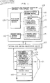
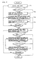
- reference numeral 101 denotes an optical disk and 102 indicates management information (hatched portion) of data in the optical disk 101.
- the management information 102 comprises: file area management information 103 to manage the recording areas of a file in the optical disk; used area management information 104 to manage the areas in which the deleted invalid data is recorded; and erased area management information 105 to manage the recordable areas from which data have already been erased.
- Reference numeral 106 denotes a file layout example in the optical disk; 107 indicates optical disk control means to record, reproduce, and erase for the optical disk 101; and 108 represents a writable type optical disk recording and managing system to manage the optical disk 101.
- Reference numeral 111 denotes area managing means for managing the management information 102 in the optical disk 101.
- the management information 102 is read out of the optical disk 101 each time it is referred, the processing speed decreases. Therefore, in many cases, the management information 102 is buffered into a high speed storage medium such as a memory or the like and is referred.
- the management information buffered by the area managing means 111 is shown as file area management information 113, used area management information 114, and erased area management information 115.
- the writable type optical disk recording managing system 108 includes: recording position deciding means 120 for deciding the recording position of the file by using the used area management information 114 and erased area management information 115; and file name managing means 109 for discriminating the recording position of a file by the file area management information 113.
- Reference numeral 110 denotes erased area making means which uses the idle time of the operating system or the like and is made operative asynchronously with the recording timing of the file and performs the erasing process of the used areas and the garbage collection of the used areas or erased areas which were distributed and prepares for the next recording process (hereinafter, referred to as an integrating process).
- the present invention is characterized by the algorithm for the file recording process in the embodiment by the recording position deciding means 120 in Fig. 1 in order to preferentially assign from the erased area and the algorithm for the activating process and its integrating process of the erased area making means 110 which is activated asynchronously with the recording timing of the file and executes the erasing process of the used area.
- Such algorithms will now be sequentially explained hereinbelow.
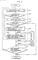
- Fig. 2 shows the algorithm to decide the file recording position in the embodiment by the recording position deciding means 120 in Fig. 1.
- the optimum erased area is selected from the erased area management information 115.
- step 202 on the basis of the result of step 201, if the erased area exists, step 206 follows. If no erased area is assigned, step 203 follows.
- step 206 the overwriting and verification for the recording area decided in step 201 are instructed to the optical disk control section 107.
- the optimum used area is selected from the used area management information 114.
- step 205 on the basis of the result of step 203, if a used area exists, step 205 follows.
- step 205 the erasing process of the recording area decided in step 203 is performed by the erased area making means 110 and step 206 then follows. Further, in step 207, a check is made to see if the whole file has been recorded or not. If any unrecorded portion still remains, the processing routine from step 201 is repeated. On the other hand, in the erased area making means 110, the discrimination with respect to the activation of the integrating process shown in the algorithm of Fig. 8 is executed in parallel. Therefore, when the recording area overflows, the integrating process is activated. After completion of the integrating process, the recording process of the file is again performed.
- the use state of each area in the optical disk is classified into three states of the using area, used area, and erased area and is managed.
- the algorithm to preferentially select from the erased area is used for the recording position deciding block as shown in Fig. 2.
- Figs. 9 to 15 show practical examples in the case of recording a file by the algorithms of Figs. 5 and 6.
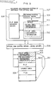
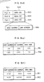
- Fig. 9 shows examples of the file area management information 103 or 113, erased area management information 105 or 115, and used area management information 104 or 114 in Fig. 1.
- Figs. 9(a), 9(b), and 9(c) show the examples in the case of managing each area on a block unit basis of a fixed length.
- Figs. 9(d), 9(e), and 9(f) show the examples in the case of managing the area of a variable length by the start address and size or end address.
- Figs. 10 to 15 describe the cases of Figs. 9(d) to 9(f) where the areas of a variable length are managed.
- Fig. 9(d) shows the file area management information 103 or 113.
- Reference numeral 941 denotes a file identifier (file ID) to discriminate a file and 942 indicates area information to record the file content. Actually, each area information is shown by the head address and end address of the area as shown by reference numeral 946. On the other hand, in the case where the file content is separately recorded in a plurality of areas, the areas are shown.
- reference numeral 943 denotes an example in which a file A is recorded in an area 106.
- reference numerals 944 and 945 show that files B and C are recorded in areas 102 and 100.
- Fig. 9(e) shows the example of the used area management information 104 or 114 which is recorded in each of the independent used areas.
- Reference numeral 951 shows a state in which the start address, end address, and size are recorded with respect to a certain unused area.
- Reference numeral 952 and subsequent reference numerals also indicate similar states.
- the unused area can be designated by only the start address and end address, by also recording the size, it can be compared with the file size when a file is written and the unused area into which data will be recorded can be selected at a high speed.
- Fig. 9(f) shows an example of the erased area management information 105 or 115 which is recorded into each independent erased area in a manner similar to Fig. 9(e).
- step 501 in Fig. 5 an area larger than the file size to be recorded is searched from the erased area management information.
- step 502 if a proper large area is selected in step 501, step 503 follows. If no area cannot be selected, step 504 follows.
- step 503 the difference between the size of the area selected in step 501 with the file size is calculated.
- the size of the remaining area after the recording is equal to or smaller than a preset size, the selected area is abandoned and the processing routine is again returned to step 501 and the next area is selected.
- step 508 follows and the recording of the file into the selected area is instructed to the device driver.
- the discriminating step 503 is provided to prevent the fragmentation phenomenon in which areas of a small size discretely exist.
- the erased area which is equal to or smaller than the file size is searched in step 504. If a proper small erased area is selected in step 504 and the existence of such a proper small erased area is determined in step 505, step 506 follows. If no small erased area cannot be selected, the processing routine is finished by regarding that the recording area overflows. Then, the processing routine advances to the selecting routine of an unused area. If the size of the selected area is equal to or smaller than the preset size in step 506, the selected area is abandoned and the processing routine is again returned to step 504 and the next area is selected.
- step 507 follows.
- step 507 a check is made to see if the area of the file size has completely been selected or not. If NO in step 507, step 504 follows and the next area to record the remaining portion of the file is searched.
- the optimum value of the preset size which is used as a discriminating condition in steps 503 and 506 is determined in dependence on the sector size of the optical disk or the size of file which is mainly recorded. In general, in the case where the managing system is used to record a file of a large size such as image data or the like, the optimum value of the preset size is set to a large value. On the contrary, when the managing system is used to record a file of a small size such as a text file or the like, it is set to a small value.
- Steps 601 to 608 in Fig. 6 correspond to steps 501 to 508 in Fig. 5.
- the algorithms in Figs. 5 and 6 relate to examples in the embodiment.
- the conditions can be added or deleted in a manner such that the discriminating condition of step 503 is omitted or the like in accordance with the situation.
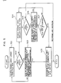
- Fig. 8 is a diagram explaining an example of the algorithm to discriminate the activation of the integrating process by the erased area making means.
- step 801 a check is made to see if the scheduling time of the operating system is a predetermined count or more or less. If it is the predetermined count or more, it is determined to be the idle time of the operating system and step 805 follows and the integrating process is executed. If the scheduling time is smaller than the predetermined count, step 802 follows. Since the integrating process requires a relatively long processing time, it is effective to execute the integrating process asynchronously with the recording of a file by using the idle time or the like of the operating system. In step 802, a check is made to see if an event indicative of the lack of recording area has been generated or not.
- step 806 follows. If NO, step 803 follows. In step 803, a check is made to see if no erased area of the preset size or smaller exists or not. If no erased area of the preset size or smaller exists, that is, if YES in step 803, step 806 follows. If NO, step 804 follows. In step 804, after completion of the discriminating steps 801 to 803, a check is made to see if an event to require other process for the operating system has been generated or not. If NO in step 804, step 806 follows and the count value of the scheduling time of the operating system is increased and the processing routine is returned to step 801. If YES in step 804, the process to discriminate the activation of the integrating process is finished and the other process requested is executed.
- step 701 the process is divided into two processes: the erasing process of the used area (steps 701 to 706); and the integrating process of a plurality of discontinuous areas (steps 707 to 713).
- step 701 the used area is searched from the used area management information.
- step 702 the presence or absence of the searched area is discriminated on the basis of the result of step 701. If the used area exists, that is, if YES in step 702, step 703 follows and a check is made to see if the searched used area is a predetermined size or larger or not.
- step 705 follows. If NO, step 704 follows. In step 704, if the adjacent erased areas before and after the area exist, a check is made to see if the total size of the areas including the adjacent erased areas is a preset size or larger or not. If it is the preset size or more, step 705 follows. If it is smaller than the preset size in step 704, step 701 follows and the next area is searched and the processing routine from step 701 is repeated. In step 705, the erasing process of the used area is executed and the resultant area is transferred from the used area management information to the erased area management information.
- step 707 the two adjacent used areas or erased areas are searched.
- step 708 if the searched areas exist on the basis of the result of step 707, the processing routine advances to step 709. If NO, the integrating process is finished.
- step 709 the time which is required for the integrating process of the two adjacent areas is calculated and if the time is a predetermined time or shorter, step 711 follows and the process is executed. If the time is the predetermined time or longer, step 710 follows.
- step 710 a check is made to see if the execution is allowed or not. If YES, step 711 follows. If NO, step 712 follows.
- the average time can be calculated by counting the number of sectors necessary to move the file which is sandwiched by the two areas. If it is necessary to largely move the file, it takes a fairly long time to remarkably rewrite the data in the optical disk, so that there is a case where an obstruction such that the other processes are stopped occurs. Therefore, it is proper to ask the user or the like to see if the processes should be executed or not before the start of the processes as mentioned above.
- step 711 the file is moved and the process to erase the used area after the integration is executed and the processing routine advances to step 712.
- step 712 the continuation of the process is inquired. If the process is continued, step 707 follows and the process is executed. If the process is not continued, the integrating process is finished.
- FIG. 10 to 15 reference numerals 1000 to 1006 denote file layouts in the optical disk 101 in each state.
- Reference numerals 1101a to 1106a, 1101b to 1106b, and 1101c to 1106c show schematic diagrams of the management information in three areas. Actually, they have the formats of Figs. 9(d) to 9(f). In each diagram, the simplified block diagram is used and no practical numerical value is shown. The hatched portion in each diagram indicates the using area (file content), the mesh portion represents the used area, and the other portions represent the erased areas. For instance, Fig.
- FIG 10 shows an example in which the files A, B, C, and E are recorded as the using areas and the portion in which the file D was recorded is erased and managed as the erased area.
- the virgin area in which no data is used yet is also handled as an erased area.
- Fig. 11 shows an example in the case of additionally recording the file F into Fig. 10.
- the area of the old file D smaller than the size of file F is determined to be improper in step 501.
- Fig. 12 shows a state in which the files A and C were deleted from the state of Fig. 11. Although the areas in which the files A and C were recorded are released and can be used again, the erasing process is not executed yet and those areas are registered into the used area management information 1103c. Further, Fig. 13 shows an example in the case where the integrating process was activated from the state of Fig. 12. In accordance with the result of step 703 in Fig. 7, the area of the old file A is determined to be improper. On the basis of the result of the discrimination of step 704, the area of the old file C having the adjacent erased area is erased and the resultant area is transferred from the erased area management information 1103b to the erased area management information 1104b. Fig.
- FIG. 14 shows an example in the case where the file G is recorded in addition to the state of Fig. 13. In this case, the integrating process of the areas of the old files D and C is executed and the resultant area is selected in step 501 in the algorithm of Fig. 5 and the file G is recorded.
- Fig. 15 shows an example in the case where the file G is recorded in the state of Fig. 12. In this case, since an erased area larger than the file size cannot be selected by steps 501 and 502 in the algorithm of Fig. 5, an erased area which is equal to or smaller than the file size is selected in steps 504 to 507 and divided into two areas and recorded.
- the blank area management information and file area management information are also recorded into the same medium by setting a predetermined area. Therefore, each time a file is updated, the rewriting operations are frequently executed in such a predetermined area. Such a problem also becomes one of the reasons such that the magnetic medium type managing method is improper for the optical disk.
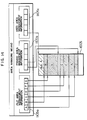
- Fig. 16 shows a construction in which a hysteresis information converting section 1300 is added to Fig. 1.
- Reference numeral 1601 denotes file information to record the file area management information and the difference information (hereinafter, referred to as hysteresis information) indicative of the updating content;
- 1602 indicates area information to record the used area management information and erased area management information and their hysteresis information;
- 1300 represents the hysteresis information converting section for respectively converting the file information 1601 in the optical disk into the format of the file area management information and converting the area information 1602 into the formats of the used area management information and erased area management information and for loading the resultant information into the area managing means 111.
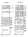
- Fig. 17(a) shows an example of the format of the file information 1601.
- Fig. 17(b) shows the example of the format of the area information 1602.
- Figs. 17(a) and 17(b) show the case of Fig. 18(b) where the files A and C were deleted from Fig. 18(a) and the erasing process was executed.
- Reference numerals 1711 to 1715 in Fig. 17(a) denote hysteresis information of the file management information; 1700 indicates a processing code representative of the content of the updating process; 00 shows the making of a file; FF a deletion of a file; 01 the updating of a file.
- Reference numeral 1701 denotes a file identifier and 1702 and 1703 indicate area information in which the file is stored. Each area is shown by the head addreass and end address. In the case where the file is divided and recorded into a plurality of areas, the areas are shown.
- reference numerals 1811 to 1816 denote hysteresis information of the erased area management information; 1800 indicates a status code representative of the status of the unused area; 00 shows the release of an area; and FF indicates that an area was used by the recording of a file.
- the hysteresis information 1812 denotes that a file was recorded into the unused area (addresses 450 to 600). In the example, the diagram is shown by assuming that no erased area exists for simplicity of explanation.
- Figs. 17(a) and 17(b) correspond to Figs. 9(d) and 9(f).
- the file area management information and erased area management information which were converted by the hysteresis information converting section 1300 so as to have the same formats as those of the file area management information of Fig. 9(d) and of the erased area management information of Fig. 9(f) are loaded in the area managing means 111.
- the hysteresis information 1714 and 1715 of the files A and C are recorded in the file information 1601.
- the hysteresis information 1812 and 1813 indicating that the areas 105 and 106 were used and the hysteresis information 1814, 1815, and 1816 indicating that the areas of the files A and B before updating were released are written into the area information 1602.
- the file area management information and blank area management information in the area managing means 111 are also simultaneously updated and rewritten into the formats of Figs. 9(d) and 9(f).
- the file information 1601 and management information 1602 are converted into the newest file area management information, erased area management information, and used area management information with reference to the hysteresis information by the hysteresis information converting section 1300 and the converted information are stored into the area managing means 111.
- the change of the file area management information, erased area management information, and used area management information after completion of the converting process they are directly changed in the area managing means 111 and managed in the newest state.
- those information are not rewritten into the same sector but the hysteresis information indicative of the content of the change is written into the file information 1601 and area information 1602. Therefore, the area in the optical disk 101 into which the management information is recorded does not need to be frequently rewritten. The deterioration of the optical disk due to the difference of the frequency of the rewriting operations can be prevented.
Abstract
Description
- The present invention relates to an optical disk which is used to record data and, more particularly, to system and method for managing recording areas on a writable type optical disk which is used in a data file apparatus or the like for a computer.
- Hitherto, as an external memory medium for a computer, a writable magnetic recording medium such as floppy disk, hard disk, or the like has been used. In recent years, the use of an optical disk having a large memory capacity of hundreds of megabytes or more has been started as an external memory medium for a computer. On the other hand, in association with the advancement of the optical disk technique, the use of not only the read only type or WORM type optical disk but also the writable type optical disk has been studied.
- The phase transition type optical disk and the magneto-optical disk have been developed as the techniques of the present writable type optical disk. However, the present techniques have several problems. Particularly, there are problems such that the overwriting technique is not completed yet, the reliability of disk is not so high, the seeking time is long (the access speed is slow), and the like. With respect to the overwriting technique, the development including the phase transition type optical disk has been progressed. However, it does not reach the practical use stage yet. In the present technique, the processing speed is slow because in order to rewrite data, the system must wait until the disk rotates once to erase the data which has already been written, and thereafter, new data is rewritten.
- On the other hand, the slower seeking time as compared with that in the case of the magnetic medium becomes a large cause of the necessity of a managing system different from that for the magnetic medium as a managing system of the optical disk. Further, in terms of the reliability as well, there still remains a problem of the deterioration of the disk such that a difference of error rate occurs due to the frequent rewritting operations, or the like.
- As an example of application as an external memory device for a computer, a managing system similar to that for the ordinary magnetic medium is used from an operating system by using the rewritable characteristic.
- A managing system of the magnetic medium type will now be described with reference to Figs. 3 and 4. In the managing system of the magnetic medium type, the area in the medium is divided into a plurality of areas of a predetermined size and the areas are managed by using a table for recording the connecting state of a discontinuous file which exists in the blank area or a plurality of areas every area. Each of the areas is constructed on a block unit basis of a fixed length size of ordinarily about a few kilobytes. Fig. 3 shows such a table comprising file
area management information 312 to record files and blankarea management information 311 to manage the recordable blank areas. File name managing means 308 manages the file recording blocks on the basis of the filearea management information 312. Recording position deciding means 309 decides the recording position on the basis of the blankarea management information 311 in the case where a file is additionally recorded. Since data can be overwritten onto the magnetic medium, there is no need to wait for the rotation of the disk to erase as in the case of the optical disk. Therefore, the operating system doesn′t need to discriminate whether the area to record a file is the area which has previously been used or the area from which data has already been erased (including a virgin area). The recording position deciding means 309 assigns the blank area to record a file by using an algorithm shown in Fig. 4. - In
step 401 in Fig. 4, the blank areas are sequentially searched from the low address side by using the blankarea management information 311. Instep 402, on the basis of the result ofstep 401, if a blank area exists,step 403 follows and if no blank area exists, it is regarded that a recording error occurs due to the area overflow, and the processing routine is finished. Instep 403, the overwriting into the blank area searched instep 401 and the verification are instructed to an opticaldisk control section 306. Instep 404, a check is made to see if the whole file has been recorded or not. If not-recorded portion still remains, the processing routine fromstep 401 is repeated. - However, the problem of the processing speed occurs in the case where the algorithm of Fig. 4 is applied to the writable type optical disk in which the overwriting operation cannot be performed. In the algorithm of Fig. 4, the blank area which needs the erasing process and has previously been used on the low address side is preferentially assigned. Therefore, the recording processing speed becomes slow as compared with the case of assigning the blank area from which data has already been erased on the high address side.
- Further, according to the magnetic medium type managing system, since the blank areas are managed on a block unit basis, in particular, there is a problem of the recording area management such as release or reuse of the recording area. For instance, the released blank blocks of a small size discretely exist due to the deletion, addition, or the like of the file. In the case of newly adding a file to the medium in such a using state, in general, the operating system searches the blank block from the low address side and sequentially records a part of the file, so that the file is divided into a plurality of blocks and discretely exists in the medium.
- On the other hand, in the optical disk of a slow access time, it is desired to continuously record data. This is because the reproducing processing efficiency can be fairly improved since the extra seeking operation is prevented and a plurality of sectors can be read out in a lump upon reproduction of the file. Therefore, in the managing method of the magnetic medium type, there are problems such that the file content is distributed, it takes a time to move the head or to rotate the disk upon reading of the file, the reproducing processing speed becomes extremely slow, and the like, so that such a method is improper as a managing system of the optical disk.
- In addition, in the case of also commonly using the magnetic medium type managing system, a problem of deterioration of the disk also occurs. For instance, each time the file is updated, the rewriting operations frequently occur for the fixed area in which area management information or the like is recorded. Therefore, the number of rewriting times of only a special block in the optical disk remarkably increases, the difference of frequency of the local rewriting operations occurs, and such a difference can easily become a cause of the difference of error rate. Particularly, the significant information such as area management information to manage the whole optical disk is frequently recorded in the fixed area on the medium in order to first read out such information when the system is set. If such management information is obstructed, there is a large danger such that the whole medium cannot be used.
- It is an object of the present invention to provide system and method for managing recording areas of a writable type optical disk which can avoid the problem of the overwriting of the writable type optical disk, the problem of the decrease in access speed due to the cause of the discrete recording of a file, and the problem of the reliability of the optical disk due to the difference of the frequency of the local rewriting operation.
- To accomplish the above object, according to the invention, the use state of each area in the optical disk is classified into three states of the using area into which valid data is recorded, the used area in which invalid data is recorded, and the erased area from which data has already been erased and into which new data can be rewritten, and the management is performed.
- When the file is assigned, the algorithm to preferentially select from the erased area by the recording position deciding means is used. On the other hand, if the erased area to record a file lacks, the erasing process of the used area or the integrating process (garbage collection) of the erased area is executed. The integrating process has erased area making means for making the erased area by using the idle time of the processes or the like. By the above construction, the characteristic such that overwriting cannot be executed is covered and the recording processing speed can be improved.
- In addition, the invention can also further use the following construction as a construction to solve the problem of the frequency of the rewriting operations for only the special area. The file system has therein: a converting section to convert the hysteresis information as recording information of the updating content in the optical disk into the format of area information (using file entry, list of unused areas); and a memory to store the converted area information. For the change of the area information in association with the updating of the file or the like, the area information in the memory is directly updated and the hysteresis information indicative of the change content is written into the erased area or used area in the optical disk. Therefore, there is no need to rewrite the area information in the optical disk. The area information in the memory is recovered to the newest form and loaded by the converting section with reference to the hysteresis information in the optical disk when the optical disk is exchanged. According to the above method, the number of rewriting times for the special area on the optical disk is reduced and the problem of the reliability due to the deterioration of the optical disk and the like can be solved.
- Further, the invention comprises: a file entry to discriminate the file recorded area in the optical disk; and a file system to manage data on a file unit basis by using an unused area list indicative of the recordable area. The area designation information in the file entry in the management information is described by the head of the area and the size or end position of the area for one or more continuous areas. The allocation of the file is preferentially executed from the unused area of a large size. With such a construction, the simple area management such as integration of the unused areas or the like can be performed and the file can be assigned to the continuous areas and the reproducing processing speed can be improved.
-
- Fig. 1 is an arrangement diagram of a writable type optical disk recording managing system according to an embodiment;
- Fig. 2 shows an algorithm for a file recording area in the embodiment;
- Fig. 3 is an arrangement diagram (magnetic medium type) of a writable type optical disk recording managing system of a conventional example;
- Fig. 4 shows an algorithm (magnetic medium type) for a file recording area of a conventional example;
- Fig. 5 shows an example of an area assigning algorithm of erased areas in the embodiment;
- Fig. 6 shows an example of an area assigning algorithm of used areas in the embodiment;
- Fig. 7 shows an example of a method of executing an integrating process (garbage collection) of used/erased areas;
- Fig. 8 shows an example of a method of discriminating the activation of the integrating process by erased area making means;
- Figs. 9(a), 9(b), and 9(c) show examples of area information in the case of managing the areas on a block unit basis of a fixed length;
- Figs. 9(d), 9(e), and 9(f) show examples of area information in the case of managing the areas on a unit basis of continuous areas of a variable length;
- Figs. 10 to 15 show practical examples of the updating of a file in the embodiment;
- Fig. 16 is an arrangement diagram of the writable type optical disk recording and managing system in the case of updating the management information by using hysteresis information according to the embodiment;
- Figs. 17(a) and 17(b) show examples of area information in the case of using the hysteresis information; and
- Figs. 18(a) and 18(b) show practical examples of the updating of a file in the case of using the hysteresis information.
- System and method for managing recording areas of a writable type optical disk in an embodiment of the present invention will be described with reference to Figs. 1, 2, and 5 to 18.
- In Fig. 1,
reference numeral 101 denotes an optical disk and 102 indicates management information (hatched portion) of data in theoptical disk 101. Themanagement information 102 comprises: filearea management information 103 to manage the recording areas of a file in the optical disk; usedarea management information 104 to manage the areas in which the deleted invalid data is recorded; and erasedarea management information 105 to manage the recordable areas from which data have already been erased.Reference numeral 106 denotes a file layout example in the optical disk; 107 indicates optical disk control means to record, reproduce, and erase for theoptical disk 101; and 108 represents a writable type optical disk recording and managing system to manage theoptical disk 101. Reference numeral 111 denotes area managing means for managing themanagement information 102 in theoptical disk 101. In general, if themanagement information 102 is read out of theoptical disk 101 each time it is referred, the processing speed decreases. Therefore, in many cases, themanagement information 102 is buffered into a high speed storage medium such as a memory or the like and is referred. In Fig. 1, the management information buffered by the area managing means 111 is shown as filearea management information 113, usedarea management information 114, and erasedarea management information 115. The writable type optical diskrecording managing system 108 includes: recording position deciding means 120 for deciding the recording position of the file by using the usedarea management information 114 and erasedarea management information 115; and file name managing means 109 for discriminating the recording position of a file by the filearea management information 113.Reference numeral 110 denotes erased area making means which uses the idle time of the operating system or the like and is made operative asynchronously with the recording timing of the file and performs the erasing process of the used areas and the garbage collection of the used areas or erased areas which were distributed and prepares for the next recording process (hereinafter, referred to as an integrating process). - The present invention is characterized by the algorithm for the file recording process in the embodiment by the recording position deciding means 120 in Fig. 1 in order to preferentially assign from the erased area and the algorithm for the activating process and its integrating process of the erased area making means 110 which is activated asynchronously with the recording timing of the file and executes the erasing process of the used area. Such algorithms will now be sequentially explained hereinbelow.
- Fig. 2 shows the algorithm to decide the file recording position in the embodiment by the recording position deciding means 120 in Fig. 1. In
step 201 in Fig. 2, the optimum erased area is selected from the erasedarea management information 115. Instep 202, on the basis of the result ofstep 201, if the erased area exists,step 206 follows. If no erased area is assigned,step 203 follows. Instep 206, the overwriting and verification for the recording area decided instep 201 are instructed to the opticaldisk control section 107. Instep 203, in place of the erased area, the optimum used area is selected from the usedarea management information 114. Instep 204, on the basis of the result ofstep 203, if a used area exists,step 205 follows. If no used area exists, the processing routine is finished by regarding that the recording error occurs due to the recording area overflow. Instep 205, the erasing process of the recording area decided instep 203 is performed by the erased area making means 110 and step 206 then follows. Further, instep 207, a check is made to see if the whole file has been recorded or not. If any unrecorded portion still remains, the processing routine fromstep 201 is repeated. On the other hand, in the erased area making means 110, the discrimination with respect to the activation of the integrating process shown in the algorithm of Fig. 8 is executed in parallel. Therefore, when the recording area overflows, the integrating process is activated. After completion of the integrating process, the recording process of the file is again performed. - The details of the algorithms for the discrimination of the optimum areas in
steps - As explained above, according to the embodiment, as shown in the construction of Fig. 1, the use state of each area in the optical disk is classified into three states of the using area, used area, and erased area and is managed. When a file is assigned, the algorithm to preferentially select from the erased area is used for the recording position deciding block as shown in Fig. 2. By using such a construction, the problem in the magnetic medium type managing system such that the recording processing speed is slow in the overwriting mode can be improved.
- Figs. 9 to 15 show practical examples in the case of recording a file by the algorithms of Figs. 5 and 6. Fig. 9 shows examples of the file
area management information area management information area management information - Fig. 9(d) shows the file
area management information Reference numeral 941 denotes a file identifier (file ID) to discriminate a file and 942 indicates area information to record the file content. Actually, each area information is shown by the head address and end address of the area as shown byreference numeral 946. On the other hand, in the case where the file content is separately recorded in a plurality of areas, the areas are shown. For instance, in Fig. 9(d),reference numeral 943 denotes an example in which a file A is recorded in anarea 106. Similarly,reference numerals 944 and 945 show that files B and C are recorded inareas - Fig. 9(e) shows the example of the used
area management information Reference numeral 951 shows a state in which the start address, end address, and size are recorded with respect to a certain unused area.Reference numeral 952 and subsequent reference numerals also indicate similar states. Although the unused area can be designated by only the start address and end address, by also recording the size, it can be compared with the file size when a file is written and the unused area into which data will be recorded can be selected at a high speed. Fig. 9(f) shows an example of the erasedarea management information - First, the optimum area assigning algorithms of Figs. 5 and 6 will now be described. In
step 501 in Fig. 5, an area larger than the file size to be recorded is searched from the erased area management information. Instep 502, if a proper large area is selected instep 501,step 503 follows. If no area cannot be selected,step 504 follows. Instep 503, the difference between the size of the area selected instep 501 with the file size is calculated. When the size of the remaining area after the recording is equal to or smaller than a preset size, the selected area is abandoned and the processing routine is again returned to step 501 and the next area is selected. If the size of the selected area is larger than the preset size,step 508 follows and the recording of the file into the selected area is instructed to the device driver. The discriminatingstep 503 is provided to prevent the fragmentation phenomenon in which areas of a small size discretely exist. When an erased area larger than the file size cannot be found out, the erased area which is equal to or smaller than the file size is searched instep 504. If a proper small erased area is selected instep 504 and the existence of such a proper small erased area is determined instep 505,step 506 follows. If no small erased area cannot be selected, the processing routine is finished by regarding that the recording area overflows. Then, the processing routine advances to the selecting routine of an unused area. If the size of the selected area is equal to or smaller than the preset size instep 506, the selected area is abandoned and the processing routine is again returned to step 504 and the next area is selected. If the size of the selected area is larger than the preset size,step 507 follows. Instep 507, a check is made to see if the area of the file size has completely been selected or not. If NO instep 507,step 504 follows and the next area to record the remaining portion of the file is searched. The optimum value of the preset size which is used as a discriminating condition insteps - In the embodiment, quite the same algorithm is also used with respect to the used area selecting algorithm in Fig. 6.
Steps 601 to 608 in Fig. 6 correspond tosteps 501 to 508 in Fig. 5. The algorithms in Figs. 5 and 6 relate to examples in the embodiment. For instance, the conditions can be added or deleted in a manner such that the discriminating condition ofstep 503 is omitted or the like in accordance with the situation. - Fig. 8 is a diagram explaining an example of the algorithm to discriminate the activation of the integrating process by the erased area making means. In
step 801, a check is made to see if the scheduling time of the operating system is a predetermined count or more or less. If it is the predetermined count or more, it is determined to be the idle time of the operating system and step 805 follows and the integrating process is executed. If the scheduling time is smaller than the predetermined count,step 802 follows. Since the integrating process requires a relatively long processing time, it is effective to execute the integrating process asynchronously with the recording of a file by using the idle time or the like of the operating system. Instep 802, a check is made to see if an event indicative of the lack of recording area has been generated or not. if YES,step 806 follows. If NO,step 803 follows. Instep 803, a check is made to see if no erased area of the preset size or smaller exists or not. If no erased area of the preset size or smaller exists, that is, if YES instep 803,step 806 follows. If NO,step 804 follows. Instep 804, after completion of thediscriminating steps 801 to 803, a check is made to see if an event to require other process for the operating system has been generated or not. If NO instep 804,step 806 follows and the count value of the scheduling time of the operating system is increased and the processing routine is returned to step 801. If YES instep 804, the process to discriminate the activation of the integrating process is finished and the other process requested is executed. - An example of the algorithm to select the area to execute the process in the case of the integrating process will now be described with reference to Fig. 7. In Fig. 7, the process is divided into two processes:
the erasing process of the used area (steps 701 to 706); and the integrating process of a plurality of discontinuous areas (steps 707 to 713). Instep 701, the used area is searched from the used area management information. In thenext step 702, the presence or absence of the searched area is discriminated on the basis of the result ofstep 701. If the used area exists, that is, if YES instep 702,step 703 follows and a check is made to see if the searched used area is a predetermined size or larger or not. If the searched area size is equal to or larger than the predetermined size,step 705 follows. If NO,step 704 follows. Instep 704, if the adjacent erased areas before and after the area exist, a check is made to see if the total size of the areas including the adjacent erased areas is a preset size or larger or not. If it is the preset size or more, step 705 follows. If it is smaller than the preset size instep 704,step 701 follows and the next area is searched and the processing routine fromstep 701 is repeated. Instep 705, the erasing process of the used area is executed and the resultant area is transferred from the used area management information to the erased area management information. In thediscriminating steps step 707, the two adjacent used areas or erased areas are searched. Instep 708, if the searched areas exist on the basis of the result ofstep 707, the processing routine advances to step 709. If NO, the integrating process is finished. Instep 709, the time which is required for the integrating process of the two adjacent areas is calculated and if the time is a predetermined time or shorter,step 711 follows and the process is executed. If the time is the predetermined time or longer,step 710 follows. Instep 710, a check is made to see if the execution is allowed or not. If YES,step 711 follows. If NO,step 712 follows. For the processing time, the average time can be calculated by counting the number of sectors necessary to move the file which is sandwiched by the two areas. If it is necessary to largely move the file, it takes a fairly long time to remarkably rewrite the data in the optical disk, so that there is a case where an obstruction such that the other processes are stopped occurs. Therefore, it is proper to ask the user or the like to see if the processes should be executed or not before the start of the processes as mentioned above. Instep 711, the file is moved and the process to erase the used area after the integration is executed and the processing routine advances to step 712. Instep 712, the continuation of the process is inquired. If the process is continued,step 707 follows and the process is executed. If the process is not continued, the integrating process is finished. - An example of the recording of the file using the algorithms of Figs. 5 and 6 will now be described. In Figs. 10 to 15,
reference numerals 1000 to 1006 denote file layouts in theoptical disk 101 in each state. Reference numerals 1101a to 1106a, 1101b to 1106b, and 1101c to 1106c show schematic diagrams of the management information in three areas. Actually, they have the formats of Figs. 9(d) to 9(f). In each diagram, the simplified block diagram is used and no practical numerical value is shown. The hatched portion in each diagram indicates the using area (file content), the mesh portion represents the used area, and the other portions represent the erased areas. For instance, Fig. 10 shows an example in which the files A, B, C, and E are recorded as the using areas and the portion in which the file D was recorded is erased and managed as the erased area. In the example, the virgin area in which no data is used yet is also handled as an erased area. - Fig. 11 shows an example in the case of additionally recording the file F into Fig. 10. In accordance with the algorithm of Fig. 5, the area of the old file D smaller than the size of file F is determined to be improper in
step 501. The area after the file E is selected and the file F is recorded. - Fig. 12 shows a state in which the files A and C were deleted from the state of Fig. 11. Although the areas in which the files A and C were recorded are released and can be used again, the erasing process is not executed yet and those areas are registered into the used
area management information 1103c. Further, Fig. 13 shows an example in the case where the integrating process was activated from the state of Fig. 12. In accordance with the result ofstep 703 in Fig. 7, the area of the old file A is determined to be improper. On the basis of the result of the discrimination ofstep 704, the area of the old file C having the adjacent erased area is erased and the resultant area is transferred from the erasedarea management information 1103b to the erasedarea management information 1104b. Fig. 14 shows an example in the case where the file G is recorded in addition to the state of Fig. 13. In this case, the integrating process of the areas of the old files D and C is executed and the resultant area is selected instep 501 in the algorithm of Fig. 5 and the file G is recorded. Finally, Fig. 15 shows an example in the case where the file G is recorded in the state of Fig. 12. In this case, since an erased area larger than the file size cannot be selected bysteps steps 504 to 507 and divided into two areas and recorded. - An explanation has been made above with respect to the embodiment according to the invention in the case where three management information of the using area, erased area, and used area are used and the response speed of the recording process is improved by considering the characteristic such that the overwriting of the optical disk is impossible. An explanation will now be made with respect to an embodiment in the case of improving a problem of the reliability of the optical disk due to the difference of the frequencies of the local rewriting operations as another problem of the optical disk.
- In the case where the managing system of the magnetic medium type is used, the blank area management information and file area management information are also recorded into the same medium by setting a predetermined area. Therefore, each time a file is updated, the rewriting operations are frequently executed in such a predetermined area. Such a problem also becomes one of the reasons such that the magnetic medium type managing method is improper for the optical disk.
- Therefore, in the case of using the
optical disk 101 in which the number of rewriting times which is guaranteed by the manufacturer is small, such a problem is avoided by using the construction of Fig. 16. - Fig. 16 shows a construction in which a hysteresis
information converting section 1300 is added to Fig. 1.Reference numeral 1601 denotes file information to record the file area management information and the difference information (hereinafter, referred to as hysteresis information) indicative of the updating content; 1602 indicates area information to record the used area management information and erased area management information and their hysteresis information; 1300 represents the hysteresis information converting section for respectively converting thefile information 1601 in the optical disk into the format of the file area management information and converting thearea information 1602 into the formats of the used area management information and erased area management information and for loading the resultant information into the area managing means 111. - Fig. 17(a) shows an example of the format of the
file information 1601. Fig. 17(b) shows the example of the format of thearea information 1602. Figs. 17(a) and 17(b) show the case of Fig. 18(b) where the files A and C were deleted from Fig. 18(a) and the erasing process was executed.Reference numerals 1711 to 1715 in Fig. 17(a) denote hysteresis information of the file management information; 1700 indicates a processing code representative of the content of the updating process; 00 shows the making of a file; FF a deletion of a file; 01 the updating of a file.Reference numeral 1701 denotes a file identifier and 1702 and 1703 indicate area information in which the file is stored. Each area is shown by the head addreass and end address. In the case where the file is divided and recorded into a plurality of areas, the areas are shown. In Fig. 17(b),reference numerals 1811 to 1816 denote hysteresis information of the erased area management information; 1800 indicates a status code representative of the status of the unused area; 00 shows the release of an area; and FF indicates that an area was used by the recording of a file. For instance, thehysteresis information 1812 denotes that a file was recorded into the unused area (addresses 450 to 600). In the example, the diagram is shown by assuming that no erased area exists for simplicity of explanation. - Figs. 17(a) and 17(b) correspond to Figs. 9(d) and 9(f). In the state of Fig. 18(b), the file area management information and erased area management information which were converted by the hysteresis
information converting section 1300 so as to have the same formats as those of the file area management information of Fig. 9(d) and of the erased area management information of Fig. 9(f) are loaded in the area managing means 111. - By updating from the state of Fig. 18(a) to the state of Fig. 18(b), the
hysteresis information file information 1601. Thehysteresis information areas hysteresis information area information 1602. At this time, the file area management information and blank area management information in the area managing means 111 are also simultaneously updated and rewritten into the formats of Figs. 9(d) and 9(f). - For instance, even in the case where the use of the
optical disk 101 is interrupted and removed in such a state and theoptical disk 101 is again used, it is also possible to reconstruct from thefile information 1601 andarea information 1602 in Figs. 17(a) and 17(b) recorded on theoptical disk 101 to the formats of the file area management information and erased area management information of Figs. 9(a) and 9(b) before the interruption of the use of theoptical disk 101 by the hysteresisinformation converting section 1300. - As explained above, in the file system 7, immediately after the optical disk was exchanged, the
file information 1601 andmanagement information 1602 are converted into the newest file area management information, erased area management information, and used area management information with reference to the hysteresis information by the hysteresisinformation converting section 1300 and the converted information are stored into the area managing means 111. For the change of the file area management information, erased area management information, and used area management information after completion of the converting process, they are directly changed in the area managing means 111 and managed in the newest state. For theoptical disk 101, those information are not rewritten into the same sector but the hysteresis information indicative of the content of the change is written into thefile information 1601 andarea information 1602. Therefore, the area in theoptical disk 101 into which the management information is recorded does not need to be frequently rewritten. The deterioration of the optical disk due to the difference of the frequency of the rewriting operations can be prevented. - However, if the change is frequently performed, an amount of hysteresis information in the optical disk increases and there occurs a case where the converting processing speed upon exchange of the optical disk becomes slow. Therefore, there is executed a saving process in which the
file information 1601 andarea information 1602 in the optical disk at a certain time point are rewritten into the formats of the newest filearea managing information 113, usedarea management information 114, and erasedarea management information 115 in the area managing means 111 at that time point. The updating after the saving process can be executed by writing the hysteresis information from the newly rewrittenfile information 1601 andarea information 1602 as start points. Particular, if the saving process is executed as a process just before the optical disk is exchanged, the converting processing speed when the optical disk is next used can be made high.
Claims (22)
a writable type optical disk (101) to record data and management information (102) of said data;
optical disk control means (107) for performing recording, reproducing, and erasing operations for the optical disk (101); and
a file system (108) to manage the data on a file unit basis by using said management information (102),
wherein said file system (108) has therein
file name managing means (109) for managing the relations between file names and file substances,
area managing means (111) having area management information for managing in three states of a using area in which valid data is recorded, a used area in which invalid data is recorded, and an erased area which was subjected to an erasing process so as to be rewritable in accordance with a use state of each area in the optical disk (101),
recording position deciding means (120) for deciding the recording area upon recording of new data by using erased area management information (105, 115) in said area managing means (111), and
erased area making means (110) for performing an erasing process to convert the used area into the erased area by erasing the data in the used area,
and wherein said erased area making means (110) has a mechanism to asynchronously execute the erasing process and data recording process.
wherein said file system (108) has
area management information to manage in three states of a using area in which valid data is recorded, a used area in which invalid data is recorded, and an erased area which was subjected to an erasing process so as to be rewritable in accordance with a use state of each area in the optical disk (101),
a step of deciding the area to record new data by using the erased area management information (105, 115), and
a step of asynchronously executing a process to convert the used area into the erased area by erasing the data in the used area and a data recording process.
a writable type optical disk (101) to record data and management information (102) of said data;
optical disk control means (107) for performing recording, reproducing, and erasing operations for the optical disk (101); and
a file system (108) to manage the data on a file unit basis by using said management information (102),
wherein said file system (108) has therein
file name managing means (109) for managing the relations between file names and file substances,
area managing means (111) having are management information for managing in three states of a using area in which valid data is recorded, a used area in which invalid data is recorded, and an erased area which was subjected to an erasing process so as to be rewritable in accordance with a use state of each area in the optical disk (101),
recording position deciding means (120) for deciding the recording area upon recording of new data by using erased area management information (105, 115) in said area managing means (111), and
erased area making means (110) for performing an erasing process to convert the used area into the erased area by erasing the data in the used area,
and wherein said erased area making means (110) has a mechanism to asynchronously execute the erasing process and data recording process.
wherein said file system (108) has area management information to manage in three states of a using area in which valid data is recorded, a used area in which invalid data is recorded, and an erased area which was subjected to an erasing process so as to be rewritable in accordance with a use state of each area in the optical disk (101),
for one or more continuous areas, each of said management information is described by a head of the area and a length or an end position of said area,
and said file system (108) has
a step of deciding the area to record new data by using the erased area management information (105, 115), and
a step of asynchronously executing a process to convert the used area into the erased area by erasing the data in the used area and a data recording process.
an optical disk (101) to record data and management information (102) of said data;
optical disk control means (107) for performing recording, reproducing, and erasing operations for said optical disk (101); and
a file system (108) to manage the data on a file unit basis by using said management information (102),
wherein said file system (108) has
a mechanism to manage in three states of a using area in which valid data is recorded, a used area in which invalid data is recorded, and an erased area which was subjected to an erasing process so as to be rewritable in accordance with a use state of each of the management information areas in the optical disk,
a mechanism to record hysteresis information indicative of a content of an updating process into said erased area with respect to the updating process of each of the management information in place of directly recording the result of the updating to said optical disk (101), and
a mechanism to execute an erasing process for converting the used management information area into the erased area by erasing the data in the used management information area.
wherein said file system (108) has
area management information for managing in three states of a using area in which valid data is recorded, a used area in which invalid data is recorded, and an erased area which was subjected to an erasing process so as to be rewritable in accordance with a use state of each of the areas in the optical disk (101),
a step of recording hysteresis information indicative of a content of an updating process into said erased area with respect to the updating process of each of said management information in place of directly recording the result of the updating into the optical disk,
a step of asynchronously executing an erasing process to convert used management information area (104, 114) into the erased area by erasing the data in said used management information area and the updating process of the management information, and
a step of writing hysteresis information indicative of a content of a change into the optical disk with respect to the change of the management information.
wherein said file system (108) has
area management information for managing in three states of a using area in which valid data is recorded, a used area in which invalid data is recorded, and an erased area which was subjected to an erasing process so as to be rewritable in accordance with a use state of each of the areas in the optical disk (101),
and a step of deciding the area into which new data is recorded by using the erased area management information (105, 115) has therein
a step of searching the area into which a file can be written by using the erased area management information and, in the case where the writable area could be found out as the result of said search, recording into said area, and
a step of searching the used area in the case where no writable area can be found out and, in the case where the used area was found, executing the erasing process of said used area and, thereafter, recording.
wherein said file system (108) has
area management information for managing in three states of a using area in which valid data is recorded, a used area in which invalid data is recorded, and an erased area which was subjected to an erasing process so as to be rewritable in accordance with a use state of each of the areas in the optical disk (101),
for one or more continuous areas, each of the management information is described by a head of the area and a length or an end position of said area,
and a step of deciding the area into which new data is recorded by using the erased area management information (105, 115) has therein
a step of searching the area into which a file can be continuously written by using the erased area management information (105, 115) and, in the case where the writable area could be found out as the result of the search, recording into said area, and
a step of searching the used area in the case where no writable area can be found out, preferentially performing the erasing process to such an area that the erasing process becomes minimum and into which the continuous recording can be performed and, thereafter, recording.
a step of searching the area into which the file can be continuously written by using the erased area management information (105, 115) and, in the case where the writable area could be found out as the result of the search, recording into said area, and
a step of searching the used area in the case where no writable area can be found out and, in the case where the data in the used area adjacent to the erased area was erased, preferentially executing the erasing process to such an area that the total value is larger than a length of the recording area.
a step of searching the area into which the file can be continuously written by using the erased area management information (105, 115) and, in the case where the writable area could be found out as the result of the search, recording into said area, and
a step of continuously recording into a plurality of erased areas in the case where no writable area can be found out.
wherein said file system (108) has
area management information for managing in three states of a using area in which valid data is recorded, a used area in which invalid data is recorded, and an erased area which was subjected to an erasing process so as to be rewritable in accordance with a use state of each of the areas in the optical disk (101),
a step of deciding the area into which new data is recorded by using the erased area management information (105, 115), and
a mechanism to activate at every predetermined period of time a process to convert the used area into the erased area by erasing the data in the used area.
a mechanism to check an activating condition of the erasing process to convert the used area into the erased area by erasing the data in the used area at every predetermined period of time or each time an access to the optical disk is executed, and
a mechanism to activate the erasing process only in the case where said checking mechanism decides that it is desirable to activate.
wherein said file system (108) has
area management information for managing in three states of a using area in which valid data is recorded, a used area in which invalid data is recorded, and an erased area which was subjected to an erasing process so as to be rewritable in accordance with a use state of each of the areas in the optical disk (101),
a step of deciding the area into which new data is recorded by using the erased area management information (105, 115), and
a step of asynchronously executing a process to convert the used area into the erased area by erasing the data in the used area and a data recording process,
and wherein said erasing processing step has therein a mechanism for searching the used area and selecting the optimum area to be erased from a layout relation among the areas.
wherein said file system (108) has
area management information for managing in three states of a using area in which valid data is recorded, a used area in which invalid data is recorded, and an erased area which was subjected to an erasing process so as to be rewritable in accordance with a use state of each of the areas in the optical disk (101),
a step of deciding the area into which new data is recorded by using the erased area management information (105, 115), and
a step of asynchronously executing a process to convert the used area into the erased area by erasing the data in the used area and a data recording process,
and wherein the step of selecting the recording area has a step of discriminating the optimum erased area from a layout of the areas.
wherein said file system (108) has
area management information for managing in three states of a using area in which valid data is recorded, a used area in which invalid data is recorded, and an erased area which was subjected to an erasing process so as to be rewritable in accordance with a use state of each of the areas in the optical disk (101),
a step of deciding the area into which new data is recorded by using the erased area management information (105, 115),
a step of asynchronously executing a process to convert the used area into the erased area by erasing the data in the used area and a data recording process, and
a step of performing a process of a garbage correction to integrate the erased areas in the optical disk at a predetermined time point by using the erased area management information (105, 115) and used area management information (104, 114),
and wherein the data in the used area is previously erased when executing the step of the garbage correction.
a converting section (1300) for extracting hysteresis information (1711 to 1715) recorded as said respective management information in the optical disk (101) and converting into formats which can be used by the file system, and
a memory to store the management information converted by said converting section.
an optical disk (101) to record data and management information (102) of said data;
optical disk control means (107) for performing recording, reproducing, and erasing operations for said optical disk (101); and
a file system (108) to manage the data on a file unit basis by using said management information (102),
wherein said management information (102) has a file entry to discriminate the area in which a file is recorded in the optical disk and an unused area list indicative of recordable areas, and for one or more continuous areas, area designating information in said file entry is described by a head of the area and a length or an end position of said area.
wherein as said management information, said file system (108) handles a file entry to discriminate the area in which a file is recorded in the optical disk and an unused area list indicative of recordable areas, and for one or more continuous areas, area designating information in said file entry is described by a head of the area and a length or an end position of said area.
Applications Claiming Priority (4)
| Application Number | Priority Date | Filing Date | Title |
|---|---|---|---|
| JP62404/88 | 1988-03-16 | ||
| JP63062405A JPH01236489A (en) | 1988-03-16 | 1988-03-16 | Rewritable type optical disk control system |
| JP63062404A JPH01236488A (en) | 1988-03-16 | 1988-03-16 | Rewritable type optical disk control system |
| JP62405/88 | 1988-03-16 |
Publications (3)
| Publication Number | Publication Date |
|---|---|
| EP0333165A2 true EP0333165A2 (en) | 1989-09-20 |
| EP0333165A3 EP0333165A3 (en) | 1990-09-19 |
| EP0333165B1 EP0333165B1 (en) | 1995-02-01 |
Family
ID=26403458
Family Applications (1)
| Application Number | Title | Priority Date | Filing Date |
|---|---|---|---|
| EP89104593A Expired - Lifetime EP0333165B1 (en) | 1988-03-16 | 1989-03-15 | System for managing recording areas on writable type optical disk |
Country Status (3)
| Country | Link |
|---|---|
| US (1) | US5107481A (en) |
| EP (1) | EP0333165B1 (en) |
| DE (1) | DE68920895T2 (en) |
Cited By (14)
| Publication number | Priority date | Publication date | Assignee | Title |
|---|---|---|---|---|
| EP0460916A2 (en) * | 1990-06-04 | 1991-12-11 | International Business Machines Corporation | Format and method for recording digital data on record disks with a pre-erasure need to save extra rotations |
| EP0472484A2 (en) * | 1990-08-20 | 1992-02-26 | International Business Machines Corporation | Structured data storage method and medium |
| EP0508755A2 (en) * | 1991-04-10 | 1992-10-14 | International Business Machines Corporation | Hierarchical data storage system |
| EP0510909A2 (en) * | 1991-04-23 | 1992-10-28 | International Business Machines Corporation | Storage media status maintainer |
| EP0570203A2 (en) * | 1992-05-14 | 1993-11-18 | Matsushita Electric Industrial Co., Ltd. | Optical disk for use in an optical data recording and/or reproducing apparatus |
| EP0593032A2 (en) * | 1992-10-16 | 1994-04-20 | Sony Corporation | Management of recordable area for TOC (table of contents) and recording or recording/reproducing apparatus for performing recording action based on the same TOC information |
| EP0681292A2 (en) * | 1994-04-20 | 1995-11-08 | Sony Corporation | Recording method and apparatus for recording medium |
| EP0833339A2 (en) * | 1993-04-23 | 1998-04-01 | Sony Corporation | Memory control and memory data search |
| EP0908882A2 (en) * | 1997-09-16 | 1999-04-14 | Sony Corporation | Recording apparatus, recording method and disc-shaped record medium |
| GB2338335A (en) * | 1998-06-12 | 1999-12-15 | Ricoh Kk | Optical-disc recording device |
| WO2000005717A1 (en) * | 1998-07-24 | 2000-02-03 | Matsushita Electric Industrial Co., Ltd. | Information recorded medium, information recording/reproducing method, and information recording/reproducing device |
| EP1031980A1 (en) * | 1999-02-26 | 2000-08-30 | Sony Corporation | Recording method, managing method, and recording apparatus |
| EP1031983A2 (en) * | 1999-02-26 | 2000-08-30 | Matsushita Electric Industrial Co., Ltd. | Disk control apparatus and disk apparatus using the same |
| EP1528565A1 (en) * | 2003-10-29 | 2005-05-04 | Kabushiki Kaisha Toshiba | Disk recording device and disk recording method |
Families Citing this family (44)
| Publication number | Priority date | Publication date | Assignee | Title |
|---|---|---|---|---|
| JPH0428061A (en) * | 1990-05-24 | 1992-01-30 | Matsushita Electric Ind Co Ltd | Information recording medium and information recording and reproducing device |
| US5265230A (en) * | 1990-08-29 | 1993-11-23 | Hewlett-Packard Company | Method and apparatus for determining sector status in a data storage device by writing a status of read-only, writable, or obliterated in an error recovery area of each sector |
| JPH04141867A (en) * | 1990-10-03 | 1992-05-15 | Canon Inc | File managing method |
| JP2888958B2 (en) * | 1990-10-20 | 1999-05-10 | 富士通株式会社 | File management method for partially rewritable storage media |
| JP3180366B2 (en) * | 1991-04-19 | 2001-06-25 | ソニー株式会社 | Recording / reproducing apparatus and recording / reproducing method |
| JP2731045B2 (en) * | 1991-04-30 | 1998-03-25 | シャープ株式会社 | Information recording / reproducing device |
| JP2962335B2 (en) * | 1991-06-24 | 1999-10-12 | 日本電気株式会社 | Free space search method |
| JP3241402B2 (en) * | 1991-08-01 | 2001-12-25 | ソニー株式会社 | Information recording medium |
| EP0532356B1 (en) * | 1991-09-13 | 2000-03-08 | Canon Kabushiki Kaisha | Method of recording data and information regarding defects |
| JPH0588957A (en) * | 1991-09-25 | 1993-04-09 | Olympus Optical Co Ltd | Directory format |
| US5450379A (en) * | 1991-10-09 | 1995-09-12 | Seiko Epson Corporation | Information storage medium, method of fabricating same, and drive unit for such medium |
| US5392267A (en) * | 1992-01-08 | 1995-02-21 | Olympus Optical Co., Ltd. | Optical card reading and writing method with redundant directory storage to improve reliability |
| DE69329360T2 (en) * | 1992-06-11 | 2001-03-01 | Canon Kk | Data processing device and output device |
| JP3017892B2 (en) * | 1992-09-30 | 2000-03-13 | 株式会社東芝 | File management device |
| JP2549810B2 (en) * | 1993-03-15 | 1996-10-30 | 富士通株式会社 | Optical disc manufacturing method |
| JP3132701B2 (en) * | 1993-11-05 | 2001-02-05 | キヤノン株式会社 | Information recording method |
| US5740435A (en) * | 1994-10-31 | 1998-04-14 | Sony Corporation | Data management apparatus and method for managing data of variable lengths recorded on a record medium |
| JPH08147110A (en) * | 1994-11-18 | 1996-06-07 | Sony Corp | Method and device for data recording medium management and data recording medium |
| JP3511721B2 (en) * | 1995-03-15 | 2004-03-29 | ソニー株式会社 | Information processing method and apparatus |
| JPH0916966A (en) | 1995-06-26 | 1997-01-17 | Pioneer Electron Corp | Information recording method and recording and reproducing device |
| US5701281A (en) * | 1995-07-13 | 1997-12-23 | Nec Corporation | Optical disk device capable of recording a control parameter on unused optical disk area |
| KR100215705B1 (en) * | 1996-11-02 | 1999-08-16 | 구자홍 | Method for recording information without damaging before hand recorded information |
| JPH10162560A (en) * | 1996-12-04 | 1998-06-19 | Matsushita Electric Ind Co Ltd | Video editing method and non-linear video editing apparatus |
| MY126410A (en) * | 1997-04-08 | 2006-09-29 | Sony Corp | Recording medium reproducing apparatus and control method for recording medium reproducing apparatus |
| KR100542937B1 (en) | 1997-09-17 | 2006-01-11 | 마츠시타 덴끼 산교 가부시키가이샤 | Optical disc recording apparatus, optical disc recording method, recording medium |
| US7103262B2 (en) * | 1997-09-17 | 2006-09-05 | Matsushita Electric Industrial Co., Ltd. | Optical disc recording apparatus, computer-readable recording medium recording a file management program, and optical disc |
| ID21519A (en) | 1997-09-17 | 1999-06-24 | Matsushita Electric Ind Co Ltd | EDITING DATA VIDEO AND RECORDING MEDIUMS THAT CAN BE READED BY COMPUTERS STORING AN EDITING PROGRAM |
| JPH11213633A (en) * | 1998-01-21 | 1999-08-06 | Pioneer Electron Corp | Information recorder |
| US6377526B1 (en) | 1999-04-01 | 2002-04-23 | Plasmon Ide, Inc. | Erasable WORM optical disk and method of writing thereto multiple times |
| JP2001110148A (en) * | 1999-10-04 | 2001-04-20 | Pioneer Electronic Corp | Information recording medium, its recording and reproducing method and information recording and reproducing device |
| US6598135B1 (en) | 2000-05-03 | 2003-07-22 | Plasmon Ide | System and method for defining rewriteable data storage media as write once data storage media |
| EP1292948A2 (en) * | 2000-05-30 | 2003-03-19 | Koninklijke Philips Electronics N.V. | Method of and apparatus for allocating recording space on a recording medium |
| US7133594B2 (en) * | 2000-06-26 | 2006-11-07 | Matsushita Electric Industrial Co., Ltd. | Digital recording apparatus that secures a certain number of video frames in a VOB constituting with another VOB a portion of encode stream that should be reproduced seamlessly |
| JP2002109831A (en) * | 2000-09-29 | 2002-04-12 | Toshiba Corp | Recording and reproducing device |
| JP2002170324A (en) * | 2000-11-30 | 2002-06-14 | Toshiba Corp | Recording and reproducing device with built-in storage medium |
| JP2003110976A (en) * | 2001-09-27 | 2003-04-11 | Fuji Photo Film Co Ltd | Image data transmission method, digital camera, image data storage method and apparatus, and program |
| JP2003151216A (en) * | 2001-11-12 | 2003-05-23 | Hitachi Ltd | Information recording method and information recorder |
| JP4498159B2 (en) * | 2005-02-03 | 2010-07-07 | キヤノン株式会社 | Imaging apparatus and control method thereof |
| JP2007080361A (en) * | 2005-09-13 | 2007-03-29 | Funai Electric Co Ltd | Optical disk recorder |
| US7991942B2 (en) * | 2007-05-09 | 2011-08-02 | Stmicroelectronics S.R.L. | Memory block compaction method, circuit, and system in storage devices based on flash memories |
| US7882301B2 (en) * | 2007-05-09 | 2011-02-01 | Stmicroelectronics S.R.L. | Wear leveling in storage devices based on flash memories and related circuit, system, and method |
| US20080282024A1 (en) * | 2007-05-09 | 2008-11-13 | Sudeep Biswas | Management of erase operations in storage devices based on flash memories |
| US8041883B2 (en) | 2007-05-09 | 2011-10-18 | Stmicroelectronics S.R.L. | Restoring storage devices based on flash memories and related circuit, system, and method |
| JP2014186781A (en) * | 2013-03-25 | 2014-10-02 | Hitachi-Lg Data Storage Inc | Data recording/reproducing device, archive system, and recording control method |
Citations (3)
| Publication number | Priority date | Publication date | Assignee | Title |
|---|---|---|---|---|
| EP0116366A2 (en) * | 1983-02-09 | 1984-08-22 | Hitachi, Ltd. | Method for controlling storage of data sets in memory unit |
| EP0122467A2 (en) * | 1983-03-30 | 1984-10-24 | Kabushiki Kaisha Toshiba | Image information registering/retrieving system |
| EP0328240A2 (en) * | 1988-02-08 | 1989-08-16 | International Business Machines Corporation | Managing data storage space on large capacity record media |
Family Cites Families (4)
| Publication number | Priority date | Publication date | Assignee | Title |
|---|---|---|---|---|
| JP2635023B2 (en) * | 1985-05-02 | 1997-07-30 | 株式会社日立製作所 | Label writing method for file data |
| US4791623A (en) * | 1986-04-03 | 1988-12-13 | Optotech, Inc. | File management system for use in an optical data storage system |
| US4775969A (en) * | 1986-05-15 | 1988-10-04 | Aquidneck Systems International, Inc. | Optical disk storage format, method and apparatus for emulating a magnetic tape drive |
| FR2604280B1 (en) * | 1986-09-19 | 1988-11-10 | Picard Michel | METHOD FOR MANAGING FILES ON A NON-ERASABLE INFORMATION MEDIUM |
-
1989
- 1989-03-13 US US07/322,428 patent/US5107481A/en not_active Expired - Fee Related
- 1989-03-15 DE DE68920895T patent/DE68920895T2/en not_active Expired - Fee Related
- 1989-03-15 EP EP89104593A patent/EP0333165B1/en not_active Expired - Lifetime
Patent Citations (3)
| Publication number | Priority date | Publication date | Assignee | Title |
|---|---|---|---|---|
| EP0116366A2 (en) * | 1983-02-09 | 1984-08-22 | Hitachi, Ltd. | Method for controlling storage of data sets in memory unit |
| EP0122467A2 (en) * | 1983-03-30 | 1984-10-24 | Kabushiki Kaisha Toshiba | Image information registering/retrieving system |
| EP0328240A2 (en) * | 1988-02-08 | 1989-08-16 | International Business Machines Corporation | Managing data storage space on large capacity record media |
Non-Patent Citations (8)
| Title |
|---|
| ACM TRANSACTIONS ON DATABASE SYSTEMS. vol. 12, no. 2, June 1987, NEW YORK US pages 137 - 169; S. Christodoulakis: "Analysis of Retrieval Performance for Records and Objects Using Optical Disk Technology" * |
| ANGEWANDTE INFORMATIK. APPLIED INFORMATICS. vol. 30, no. 2, February 1988, Wiesbaden, W. Germany & Sonnenschein: "Ein Fileserver mit UNIX-Snittstelle für Echtzeitanwendungen" * |
| ANGEWANDTE INFORMATIK. APPLIED INFORMATICS. vol. 30, no. 2, February 1988,Wiesbaden, W. Germany pages 81-89; Lücking & Sonnenschein: "Ein Fileserver mit UNIX-Snittstelle für Echtzeitanwendungen" * |
| Eighth IEEE Symposium on Mass Storage Systems May 1987, Tucson, Arizona, USA pages 92 - 97; K. Itao et al.: "Magneto-optical Mass Storage System with 130mm Write-once Disk Compatibility" * |
| ELECTRONICS & WIRELESS WORLD. vol. 93, no. 1608, 10 October 1986, SUTTON, Great-Britain pages 45 - 46; F. Stubbs: "IBM's PC Filing System" * |
| Proceedings of SPIE - The International Society for Optical Engineering vol. 421, June 1983, Arlington, Virginia, USA pages 10 - 19; J.H. Hoover: "Intelligent Optical Disk Controller Architecture" * |
| Proceedings of SPIE - The International Society for Optical Engineering vol. 421, June 1983, Arlington, Virginia, USA pages 20 - 30; J.B. Shaffer et al.: "Data Base and File Management Approach for Large Optical Disc Systems" * |
| Proceedings of SPIE - The International Society for Optical Engineering vol.421, June 1983, Arlington, Virginia, USA pages 10 - 19; J.H. Hoover:"Intelligent Optical Disk Controller Architecture" * |
Cited By (33)
| Publication number | Priority date | Publication date | Assignee | Title |
|---|---|---|---|---|
| EP0460916A3 (en) * | 1990-06-04 | 1993-04-21 | International Business Machines Corporation | Format and method for recording digital data on record disks with a pre-erasure need to save extra rotations |
| EP0460916A2 (en) * | 1990-06-04 | 1991-12-11 | International Business Machines Corporation | Format and method for recording digital data on record disks with a pre-erasure need to save extra rotations |
| EP0472484A2 (en) * | 1990-08-20 | 1992-02-26 | International Business Machines Corporation | Structured data storage method and medium |
| EP0472484A3 (en) * | 1990-08-20 | 1994-03-23 | Ibm | |
| EP0508755A2 (en) * | 1991-04-10 | 1992-10-14 | International Business Machines Corporation | Hierarchical data storage system |
| EP0508755A3 (en) * | 1991-04-10 | 1995-02-08 | Ibm | Hierarchical data storage system |
| US5347651A (en) * | 1991-04-23 | 1994-09-13 | International Business Machines Corporation | System for allocating worm optical medium file storage in groups of fixed size addressable areas while tracking unrecorded areas and end of volume |
| EP0510909A2 (en) * | 1991-04-23 | 1992-10-28 | International Business Machines Corporation | Storage media status maintainer |
| EP0510909A3 (en) * | 1991-04-23 | 1994-03-02 | Ibm | |
| EP0570203A3 (en) * | 1992-05-14 | 1994-01-26 | Matsushita Electric Industrial Co., Ltd. | Optical disk for use in an optical data recording and/or reproducing apparatus |
| EP0570203A2 (en) * | 1992-05-14 | 1993-11-18 | Matsushita Electric Industrial Co., Ltd. | Optical disk for use in an optical data recording and/or reproducing apparatus |
| CN1035905C (en) * | 1992-05-14 | 1997-09-17 | 松下电器产业株式会社 | Optical disk for use in an optical data recording and/or reproducing apparatus |
| EP0593032A2 (en) * | 1992-10-16 | 1994-04-20 | Sony Corporation | Management of recordable area for TOC (table of contents) and recording or recording/reproducing apparatus for performing recording action based on the same TOC information |
| EP0593032A3 (en) * | 1992-10-16 | 1996-05-01 | Sony Corp | Management of recordable area for toc (table of contents) and recording or recording/reproducing apparatus for performing recording action based on the same toc information |
| EP0833339A2 (en) * | 1993-04-23 | 1998-04-01 | Sony Corporation | Memory control and memory data search |
| EP0833339A3 (en) * | 1993-04-23 | 2002-05-02 | Sony Corporation | Memory control and memory data search |
| EP0681292A2 (en) * | 1994-04-20 | 1995-11-08 | Sony Corporation | Recording method and apparatus for recording medium |
| US5774434A (en) * | 1994-04-20 | 1998-06-30 | Sony Corporation | Methods and apparatus for recording data on and deleting already recorded data from a recording medium |
| EP0681292A3 (en) * | 1994-04-20 | 1996-01-31 | Sony Corp | Recording method and apparatus for recording medium. |
| US6052346A (en) * | 1994-04-20 | 2000-04-18 | Sony Corporation | Methods and apparatus for recording data on and deleting already recorded data from a recording medium |
| CN1097265C (en) * | 1994-04-20 | 2002-12-25 | 索尼公司 | Recording apparatus for overwriting data |
| EP0908882A2 (en) * | 1997-09-16 | 1999-04-14 | Sony Corporation | Recording apparatus, recording method and disc-shaped record medium |
| EP0908882A3 (en) * | 1997-09-16 | 2005-01-26 | Sony Corporation | Recording apparatus, recording method and disc-shaped record medium |
| GB2338335A (en) * | 1998-06-12 | 1999-12-15 | Ricoh Kk | Optical-disc recording device |
| GB2338335B (en) * | 1998-06-12 | 2000-08-16 | Ricoh Kk | Optical-disc recording device |
| WO2000005717A1 (en) * | 1998-07-24 | 2000-02-03 | Matsushita Electric Industrial Co., Ltd. | Information recorded medium, information recording/reproducing method, and information recording/reproducing device |
| EP1031983A2 (en) * | 1999-02-26 | 2000-08-30 | Matsushita Electric Industrial Co., Ltd. | Disk control apparatus and disk apparatus using the same |
| EP1031980A1 (en) * | 1999-02-26 | 2000-08-30 | Sony Corporation | Recording method, managing method, and recording apparatus |
| US6385690B1 (en) | 1999-02-26 | 2002-05-07 | Sony Corporation | Recording method, managing method, and recording apparatus |
| EP1031983A3 (en) * | 1999-02-26 | 2004-02-11 | Matsushita Electric Industrial Co., Ltd. | Disk control apparatus and disk apparatus using the same |
| US6775466B1 (en) | 1999-02-26 | 2004-08-10 | Matsushita Electric Industrial Co., Ltd. | Disk control apparatus dividing a recording area into recorded and unrecorded areas |
| EP1528565A1 (en) * | 2003-10-29 | 2005-05-04 | Kabushiki Kaisha Toshiba | Disk recording device and disk recording method |
| US7477578B2 (en) | 2003-10-29 | 2009-01-13 | Kabushiki Kaisha Toshiba | Disk recording device and disk recording method for recording and erasing titles on a disk |
Also Published As
| Publication number | Publication date |
|---|---|
| US5107481A (en) | 1992-04-21 |
| DE68920895T2 (en) | 1995-06-22 |
| EP0333165B1 (en) | 1995-02-01 |
| EP0333165A3 (en) | 1990-09-19 |
| DE68920895D1 (en) | 1995-03-16 |
Similar Documents
| Publication | Publication Date | Title |
|---|---|---|
| EP0333165A2 (en) | System for managing recording areas on writable type optical disk | |
| US8065473B2 (en) | Method for controlling memory card and method for controlling nonvolatile semiconductor memory | |
| US7610434B2 (en) | File recording apparatus | |
| EP0479535B1 (en) | File managing method | |
| JP3509285B2 (en) | Compressed data management method | |
| US5029125A (en) | Method of reading and writing files on nonerasable storage media | |
| EP0350920B1 (en) | A method of managing defective sectors in a disk-shaped information recording medium and an apparatus for performing the same | |
| US20080232210A1 (en) | Data Recording/Reproduction for Write-Once Discs | |
| US7821896B2 (en) | Data recording/reproduction for write-once discs | |
| CN112527694A (en) | Fragmentation degree alarm method and device | |
| JP4300669B2 (en) | Recording method and apparatus, and recording medium | |
| JP2831369B2 (en) | Information recording / reproducing method and system | |
| US20090030954A1 (en) | Management of multiple virtual data copies | |
| US7823032B2 (en) | Data recording/reproduction for write-once discs | |
| US20070043897A1 (en) | Method and device for storing information | |
| JPH03166634A (en) | Information recording/reproducing system | |
| JPH0778097A (en) | File rearrangement system | |
| JPH01236488A (en) | Rewritable type optical disk control system | |
| JP3707396B2 (en) | Recording method and recording apparatus | |
| JPH05342817A (en) | File management method and information recording and reproducing device | |
| JP2652388B2 (en) | Optical disk storage management method | |
| JP2569084B2 (en) | File management method | |
| JPH1186512A (en) | Data rewriting method for optical disk | |
| JPH073661B2 (en) | Information processing system and control method thereof | |
| JPH01236489A (en) | Rewritable type optical disk control system |
Legal Events
| Date | Code | Title | Description |
|---|---|---|---|
| PUAI | Public reference made under article 153(3) epc to a published international application that has entered the european phase |
Free format text: ORIGINAL CODE: 0009012 |
|
| AK | Designated contracting states |
Kind code of ref document: A2 Designated state(s): DE FR GB NL |
|
| PUAL | Search report despatched |
Free format text: ORIGINAL CODE: 0009013 |
|
| AK | Designated contracting states |
Kind code of ref document: A3 Designated state(s): DE FR GB NL |
|
| RHK1 | Main classification (correction) |
Ipc: G11B 20/12 |
|
| 17P | Request for examination filed |
Effective date: 19901128 |
|
| 17Q | First examination report despatched |
Effective date: 19930224 |
|
| GRAA | (expected) grant |
Free format text: ORIGINAL CODE: 0009210 |
|
| AK | Designated contracting states |
Kind code of ref document: B1 Designated state(s): DE FR GB |
|
| REF | Corresponds to: |
Ref document number: 68920895 Country of ref document: DE Date of ref document: 19950316 |
|
| ET | Fr: translation filed | ||
| PLBE | No opposition filed within time limit |
Free format text: ORIGINAL CODE: 0009261 |
|
| STAA | Information on the status of an ep patent application or granted ep patent |
Free format text: STATUS: NO OPPOSITION FILED WITHIN TIME LIMIT |
|
| 26N | No opposition filed | ||
| PGFP | Annual fee paid to national office [announced via postgrant information from national office to epo] |
Ref country code: GB Payment date: 19960306 Year of fee payment: 8 |
|
| PGFP | Annual fee paid to national office [announced via postgrant information from national office to epo] |
Ref country code: DE Payment date: 19960313 Year of fee payment: 8 |
|
| PGFP | Annual fee paid to national office [announced via postgrant information from national office to epo] |
Ref country code: FR Payment date: 19960315 Year of fee payment: 8 |
|
| PG25 | Lapsed in a contracting state [announced via postgrant information from national office to epo] |
Ref country code: GB Effective date: 19970315 |
|
| GBPC | Gb: european patent ceased through non-payment of renewal fee |
Effective date: 19970315 |
|
| PG25 | Lapsed in a contracting state [announced via postgrant information from national office to epo] |
Ref country code: FR Free format text: LAPSE BECAUSE OF NON-PAYMENT OF DUE FEES Effective date: 19971128 |
|
| PG25 | Lapsed in a contracting state [announced via postgrant information from national office to epo] |
Ref country code: DE Effective date: 19971202 |
|
| REG | Reference to a national code |
Ref country code: FR Ref legal event code: ST |