EP0335582A2 - Apparatus and method for detecting the end of a tape - Google Patents
Apparatus and method for detecting the end of a tape Download PDFInfo
- Publication number
- EP0335582A2 EP0335582A2 EP89302858A EP89302858A EP0335582A2 EP 0335582 A2 EP0335582 A2 EP 0335582A2 EP 89302858 A EP89302858 A EP 89302858A EP 89302858 A EP89302858 A EP 89302858A EP 0335582 A2 EP0335582 A2 EP 0335582A2
- Authority
- EP
- European Patent Office
- Prior art keywords
- tape
- reel
- pulses
- responsive
- counting
- Prior art date
- Legal status (The legal status is an assumption and is not a legal conclusion. Google has not performed a legal analysis and makes no representation as to the accuracy of the status listed.)
- Granted
Links
Images


Classifications
-
- G—PHYSICS
- G11—INFORMATION STORAGE
- G11B—INFORMATION STORAGE BASED ON RELATIVE MOVEMENT BETWEEN RECORD CARRIER AND TRANSDUCER
- G11B15/00—Driving, starting or stopping record carriers of filamentary or web form; Driving both such record carriers and heads; Guiding such record carriers or containers therefor; Control thereof; Control of operating function
- G11B15/18—Driving; Starting; Stopping; Arrangements for control or regulation thereof
- G11B15/22—Stopping means
-
- G—PHYSICS
- G11—INFORMATION STORAGE
- G11B—INFORMATION STORAGE BASED ON RELATIVE MOVEMENT BETWEEN RECORD CARRIER AND TRANSDUCER
- G11B15/00—Driving, starting or stopping record carriers of filamentary or web form; Driving both such record carriers and heads; Guiding such record carriers or containers therefor; Control thereof; Control of operating function
- G11B15/18—Driving; Starting; Stopping; Arrangements for control or regulation thereof
- G11B15/46—Controlling, regulating, or indicating speed
- G11B15/54—Controlling, regulating, or indicating speed by stroboscope; by tachometer
-
- G—PHYSICS
- G11—INFORMATION STORAGE
- G11B—INFORMATION STORAGE BASED ON RELATIVE MOVEMENT BETWEEN RECORD CARRIER AND TRANSDUCER
- G11B15/00—Driving, starting or stopping record carriers of filamentary or web form; Driving both such record carriers and heads; Guiding such record carriers or containers therefor; Control thereof; Control of operating function
- G11B15/02—Control of operating function, e.g. switching from recording to reproducing
- G11B15/05—Control of operating function, e.g. switching from recording to reproducing by sensing features present on or derived from record carrier or container
- G11B15/093—Control of operating function, e.g. switching from recording to reproducing by sensing features present on or derived from record carrier or container by sensing driving condition of record carrier, e.g. travel, tape tension
-
- G—PHYSICS
- G11—INFORMATION STORAGE
- G11B—INFORMATION STORAGE BASED ON RELATIVE MOVEMENT BETWEEN RECORD CARRIER AND TRANSDUCER
- G11B15/00—Driving, starting or stopping record carriers of filamentary or web form; Driving both such record carriers and heads; Guiding such record carriers or containers therefor; Control thereof; Control of operating function
- G11B15/18—Driving; Starting; Stopping; Arrangements for control or regulation thereof
- G11B15/46—Controlling, regulating, or indicating speed
- G11B15/48—Starting; Accelerating; Decelerating; Arrangements preventing malfunction during drive change
Definitions
- the invention relates to circuitry for precisely detecting the end of a tape in an audio or video tape transport apparatus, and for initiating the stopping of tape movement by conventional circuits upon the detection of an approaching end.
- Typical of "end-of-tape" detectors presently available are those systems which measure the amount of tape on a reel utilizing the principle that the rate at which the reel rotates as the tape is wound or unwound therefrom varies in proportion to the amount of tape on the reel.
- a first series of pulses are provided which indicate the rotational velocity of the reel, and a second series of pulses are provided for indicating the linear velocity of the tape.
- the number of pulses generated by the linear tape movement are counted during each interval of time between the pulses generated by the rotating reel.
- the accumulated counts vary in proportion to the amount of tape remaining on the respective reel being unwound, and thus can be used to indicate the approaching end-of-tape.
- a counter responsive to the tape movement pulses and the reel rotation pulses, develops a signal representing the ratio of longitudinal tape speed to reel rotational speed.
- a tape pack diameter selector produces a preselected ratio of longitudinal tape speed to reel rotational speed corresponding to a desired terminal tape pack diameter.
- a comparator compares the signal with the preselected ratio, and includes a storage register which produces a control signal which may, for example, decelerate the tape driving means when the signal and the preselected ratio achieve at least one and generally a plurality of value matches in succession.
- end-of-tape detector systems of previous discussion provide generally sophisticated means for determining the end of the tape and for decelerating the tape to a stop upon sensing the approaching end.
- systems such as those above which calculate the distance to the approaching end of the tape, or otherwise use pulses derived from a capstan or idler guide which are indicative of tape movement, require the use of a large safety cushion in terms of time or revolutions of the reel, in order to insure that the end of the tape is not ripped from the reel hub, as will happen if the tape end is actually closer than the calculated distance.
- the present invention provides a simple yet very sophisticated system for determining the precise end of a tape, while overcoming the disadvantages of previous mention. That is, the end-of-tape determined by the system is not affected by capstan slippage or other tape movement parameters which can negatively affect typical end-of-tape detectors presently being used. To this end, once the end of the tape or nearly the end of the tape is located, the corresponding position is remembered and stored as a preset end-of-tape value. When tape is wound back onto the reel, the number of revolutions accumulated also are stored.
- reel tachometers are mechanically coupled in conventional fashion to respective supply and takeup reels.
- a "counter means” include supply and takeup up/down counters coupled to respective reel tachometers, wherein the counter means in essence count each revolution of the respective reels to provide continuous data as to the distance from the "end-of-tape" (on the supply reel), or the "beginning-of-tape” (on the pickup reel).
- end-of-tape end-of-tape and beginning-of-tape
- end-of-tape is commonly used in the art and thus is used in the description hereinafter, to indicate either end of the tape.
- the reel tachometers provide the one or more pulses indicative of each of the revolutions of the respective reels.
- the system includes a microprocessor/memory means wherein, in the preferred embodiment, the memory defines in part the "counter means" of previous mention in which the preset value indicative of the true end-of-tape is stored. Under control of selected software, the collective "counter means” accumulate and also store the tach pulses corresponding to the revolutions of each reel as the tape is being moved between the supply and takeup reels.
- the junction between tape and clear leader is detected by an associated sensor means to define the true end-of-tape.
- the associated takeup counter means i.e., memory, is set to a zero value, or to some other selected reference value, at the exact point where the clear leader is spliced to the tape. Thereafter, every revolution of the takeup reel increments the takeup counter means by one or a selected number of counts as the tape is wound onto the takeup reel, and decrements the takeup counter by one or the selected number of counts, when tape subsequently is pulled off the takeup reel and returned to the supply reel.
- the true end-of-tape on the takeup reel is precisely known and is continuously updated and stored in the associated microprocessor memory via the takeup counter while winding or unwinding tape.
- the distance to the end-of-tape is stored in terms of the number of reel revolutions; that is, in terms of the number of reel tach pulses indicative of the exact number of revolutions.
- the supply reel is threaded and the clear leader-to-tape junction is detected by an associated sensor means, the corresponding end-of-tape is precisely known, and the memory associated with the supply counter means is preset.
- the distance to the true end-of-tape also continuously is known while winding tape back onto, or from, the supply reel.
- the microprocessor means When pulling tape from a reel the microprocessor means continuously monitors the memory of the counter means, and thus is aware of an approaching end-of-tape from either reel. Upon detecting an approaching end-of-tape, the microprocessor means initiates the deceleration of the tape, via a conventional transport tape speed control circuit, to a selected safe speed a preselected short distance prior to the true end-of-tape. The transport then pulls the tape the short distance at the safe speed until the associated sensor means detects the clear leader-to-tape junction, that is, the true end-of-tape. A control signal is supplied to the conventional control circuit to immediately stop the tape. The memory of the counter means is reset to the reference value corresponding to the true end-of-tape, as previously discussed.
- the counter means In the situation where a system is turned on with tape distributed on both reels, the counter means generally do not contain the preset reference values corresponding to the respective true ends-of-tape.
- the transport control system relies upon the conventional prior art end-of-tape detection technique using, for example, the tape pack diameter and ratio of tape speed to reel rotational speed information of previous mention.
- the end-of-tape detection technique reverts to the invention combination, as further described below.
- the block diagram illustrates an implementation of the invention in the environment of supply and takeup reels 12, 14, respectively, in an audio, video, instrumentation, etc., tape transport, wherein a capstan tape drive system provides the reciprocal movement of a magnetic tape 16 from reel to reel.
- a capstan tape drive system provides the reciprocal movement of a magnetic tape 16 from reel to reel.
- the reels may be an open reel or an enclosed reel cassette configuration.
- Respective tachometer disks 18, 20 and tach readout means 22, 24 are coupled in conventional fashion to the supply reel 12 and takeup reel 14, respectively, for rotation therewith.
- the tach readout means 22, 24 are coupled to a supply tachometer 26 and a takeup tachometer 28, respectively, wherein the tachometer means may generate one pulse for each full rotation of the respective reels 12, 14, or may generate hundreds of pulses as in conventional tach systems in video tape recorder apparatus.
- various types of pulse generating schemes may be employed as long as the scheme supplies a pulse count which represents the exact number of revolutions of the reel.
- the pulses representing each revolution of the supply and takeup reels are supplied as tach signals on lines 30, 32, respectively, to up/down supply and takeup counters 34, 36, respectively.
- the supply and takeup tachometers 26, 28, also supply direction signals via lines 38, 40, respectively, to the supply and takeup counters 34, 36.
- the tach signal in effect, supplies a pulse for each revolution of the respective supply and takeup reels, regardless of the size of the tape pack; that is, regardless of the diameter of the tape pack thereon.
- the tach system may supply, for example, 2000 pulses for every revolution of the reels, which pulses are manipulated via software to provide digital values which represent each revolution.
- the direction signals on lines 38, 40 consist of a high or a low logic level, indicating whether the reels are operating in the forward or reverse direction.
- the counters 34, 36 depicted herein as hardware counters, are coupled to a data bus 42 and an address bus 44.
- the buses in turn are coupled to a microprocessor means 46 which, in the embodiment of FIGURE 1, includes a memory 48 such as, for example, a 16 bit counter shown here.
- a memory 48 such as, for example, a 16 bit counter shown here.
- the supply up/down counter 34 and memory 48 comprise a supply counter means
- the takeup up/down counter 36 and memory 48 comprise a takeup counter means, wherein accordingly, "counter means” is meant to include a hardware, a software, or the hardware/software combination configuration illustrated in FIGURE 1 and described below.
- the microprocessor means 46 further provides for presetting the memory 48 to zero, or to a selected reference value, at such time as the true end-of-tape (clear leader-to-tape splice) is detected by respective sensor means 39, 41 disposed to view the tape as it is pulled from the respective reels.
- the microprocessor means 46 provides a velocity control signal on a bus 50 (corresponding to the data bus 42), as depicted in the software routine illustrated in the flow diagram of FIGURE 4.
- the control signal is supplied to a conventional capstan servo circuit 52 which, in turn, deceler severelyates a capstan 54 and thus the tape 16 to a preselected safe speed, for example, 8X play speed, in accordance with a desired deceleration or cue profile characteristic, in a process well known in the art.
- a preselected safe speed for example, 8X play speed
- the capstan servo circuit 52 stops the tape. Examples of transport servo circuits which can be used to implement the deceleration of a tape to a selected speed and a stop are well known in the art and are described, for example, in U.S. Patent No.3,736,565, issued May 29, 1973, to G.. Sidline, U.
- the microprocessor means 46 knows the tape distance, or number of revolutions, it takes to decelerate the tape to a safe speed at a point immediately prior to the true end-of-tape.
- the distance for deceleration to the selected safe speed is determined by the dynamics of the tape transport, as known in the art. Accordingly, the microprocessor means 46 is aware of when the required distance to the approaching end-of-tape is reached in the counter means, and supplies the control signal via bus 50 to direct the capstan servo circuit 52 to decelerate the tape rapidly to an 8X play speed when it reaches a predetermined point just prior to the end-of-tape.
- the tape is pulled the remaining margin (for example, 1 ⁇ 2 second) at 8X play speed until the associated sensor means 39 or 41 detects the leader-to-tape junction corresponding to the true end-of-tape.
- the tape movement then is immediately stopped by a signal to the capstan servo circuit 52 from the sensor means.
- the counter means shown herein formed of the memory 48 and counters 34, 36 may be implemented in various configurations.
- the counters 34, 36 and memory 48 may be separate 16 bit hardware counters with memory 48 implemented in software in the microprocessor means 46, as depicted in FIGURE 1.
- 32 bit counters 34, 36 may be used in an all hardware implementation, under control of the microprocessor 46.
- the entire 32 bit memory or counter means may be in the microprocessor means 46, whereby the tach pulses and direction signals are supplied directly to the means 46 in form compatible to the microprocessor.
- microprocessor means 46 is a small dedicated microcontroller with available interrupt lines
- the outputs of the tachs 26, 28 may be supplied to the microcontroller as interrupt signals.
- the microcontroller inteprets the tach pulses to thereby accumulate or subtract the number of revolutions while also determining the direction of reel rotation.
- the counter means may be implemented in hardware, in software or, as depicted in FIGURE 1, in a hardware/software combined configuration. This latter arrangement eases the time demands placed on the microprocessor means (or microcontroller) 46, while providing a scheme which, in essence, efficiently turns a 16 bit counter into a 32 bit counter.
- the memory 48 defines the portion of the counter means which stores the values indicative of the number of revolutions of the respective reels 12, 14.
- the up/down counters 34, 36 are not preset and are used to count the actual tach pulses as they are generated. Upon filling, the counters 34, 36 send a carry in the form of 16 bits to the memory 48 which slowly counts up or down depending upon the direction of tape travel.
- the reference values corresponding to the ends-of-tape detected by the sensor means 39, 41, are preset in the memory 48, and are used by the microprocessor means 46 to monitor an approaching end-of-tape and to determined the point that the deceleration process should be initiated, as further described in FIGURES 2-4.
- the tape sensor means 39, 41 of previous mention provide means for detecting the clear leader-to-tape junction, or splice point, and are disposed to view the tape at respective positions as close as possible to the respective reels to minimize the amount of leader which is pulled off the reel before detecting the junction. Since this point is precisely repeatable at either end of the tape, it is used to define the true end-of-tape.
- the sensor means 39, 41 are coupled to the capstan servo circuit 52 via respective amplifiers, and the circuit 52 provides signals to the microprocessor means 46 indicating the presence of clear leader or opaque tape. In turn, the microprocessor means 46 then directs the capstan servo circuit 52 to immediately stop the tape.
- the clear leader-to-tape junction will overshoot and pass the junction before the tape is stopped. Since the amount of overshoot will depend on the velocity of the tape, the precise position of the junction upon stopping the tape is not known. If an operator asks for further tape movement in the same direction, i.e., off the reel, the capstan servo circuit 52 will not comply. If the operator asks for tape movement back in the tape direction, the circuit 52 will move tape but only at normal play speed.
- the microprocessor means 46 sets the counter means (memory 48) to the zero or reference value indicative of the true end-of-tape.
- the tape then is pulled at whatever speed was requested.
- the memory 48 is continually being reset. As soon as tape is detected, the memory 48 starts accumulating the reel revolutions, as supplied by the respective counter 34 or 36.
- Typical of an optical sensor means which may be used as sensor means 39, 41, is that described in U. S. Patent No. 4,730,108 issued March 8, 1988 to D. Rodal, et al, and assigned to the same assignee as this application.
- FIGURE 2 depicts a graph showing time versus tape speed of operation, that is, shows a deceleration curve, for a tape transport using a typical end-of-tape detector circuit.
- the curve depicts the transport pulling tape in shuttle at 60 times playback speed as an end-of-tape is approached.
- a large time cushion is necessary to insure that the end of the tape is not closer than calculated, as would be the case when capstan slippage has occurred.
- the capstan servo begins to decelerate the tape so that the tape reaches 8X play speed by the time the calculated end-of-tape 62 is reached.
- the tape then is pulled at 8X play speed for the remaining amount of tape, over a time cushion distance A depicted herein, until the true end-of-tape 64 is reached and the capstan servo stops the transport.
- the cushion distance A is a considerable period (of the order of 20 to 30 seconds) in order to insure that the end-of-tape is not overrun.
- FIGURE 3 depicts the corresponding operation of the invention scheme of FIGURE 1, wherein the number of revolutions of, for example, the supply reel 12 as it accumulates tape, has been accurately counted by the counter means 34, 48.
- the counter 34 decrements to thereby decrement the memory 48 towards the preset zero value indicative of the true end-of-tape.
- the microprocessor means 46 is aware of the distance required to decelerate the tape to 8X play speed, and further knows the true end-of-tape from the stored reference value.
- the microprocessor means 46 knows the location of a point 70 corresponding to a remembered value, and can use the information with the known dynamic information on the transport to determine a point 68 at which deceleration should start.
- the control signal is supplied on bus 50 to initiate the deceleration of the tape by the conventional capstan servo circuit 52 to slow the tape to the desired, safe, 8X play speed at such time as it reaches the point 70.
- the tape then is pulled at the 8X play speed to the true end-of-tape 72 (corresponding to the clear leader-to-tape junction) over a relatively short cushion distance B of the order of 1 ⁇ 2 second.
- the capstan servo circuit 52 is informed, and the tape transport is stopped.
- the deceleration begins later at a point 74 as also illustrated in FIGURE 3.
- the time cushion distance B from the true end-of-tape 72 for the invention system of FIGURES 1 and 3, is of the order of 30 to 60 times shorter than the cushion distance A of prior art systems depicted in FIGURE 2.
- the much shorter cushion is possible because the true end-of-tape is precisely known, and thus the calculation of point 68 (or 74) is extremely accurate and can be relied upon.
- the process of shuttling a tape to its end and then decelerating to a stop at the true end-of-tape is substantially more efficient when using the invention. This increased efficiency is due to the fact that the precise number of revolutions to the true end-of-tape is more accurately known in the invention system illustrated in FIGURE 1.
- the counter means continually counts the reel revolutions and updates its contents, even though the invention circuit is not used unless the true end-of-tape, or nearly end-of-tape, is detected.
- the conventional circuits are aware of the calculated end-of-tape, point 62 of FIGURE 2.
- the invention end-of-tape detection circuit continues to count and store reel revolution values.
- the memory 48 of the invention stores the value corresponding to this point (70a of FIGURE 2) and, since it is closer to the true end-of-tape than is point 62, the invention circuit will control the tape movement with the closer value the next time the same end-of-tape is approached.
- the invention circuit includes a learning mode wherein the memory 48 retains the value of a point which is nearer the true end-of-tape each time the tape is pulled nearer to the true end-of-tape.
- the invention circuit will set the memory 48 and will thereafter perform the most efficient end-of-tape detection process, as depicted in FIGURE 3 and described herein.
- the conventional end-of-tape circuitry is used to control the tape transport when that same end is approached. Once an end is approached past the point depicted at 62 (FIGURE 2), and particularly if the true end-of-tape is detected, than the new, closer point or true end-of-tape will be used under control of the invention end-of-tape detection circuit.
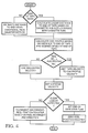
- FIGURE 4 depicts the main routine commensurate with the various operating points shown in FIGURE 3, as well as the process of determining the position of the tape and the position of the point 70, and of initiating the rapid deceleration of the tape to a stop as close as possible to the true end-of-tape 72. More particularly, the system is turned on and the routine asks if an end-of-tape is seen; that is, has the system detected a leader-to-tape junction via a sensor 39, 41.
- the invention circuit is not used and the routine estimates the distance to the point 62 using the conventional end-of-tape detection scheme normally in the tape transport apparatus, such as the tape pack diameter versus rotational speed method.
- conventional end-of-tape detection circuits are those described in U. S. Patent No. 3,834,648, issued September 10, 1974 to M. Rose, et al, and U. S. Patent No. 4,561,608 issued December 31, 1985 to D. O'Gwynn, with both assigned to the assignee of this application.
- the routine continues then to the right side of the routine where the deceleration curve, or cue profile, is calculated based on the distance to the end-of-tape and the speed desired when the point 62 (FIGURE 2) is reached.
- the routine then asks if the speed requested is greater than the calculated cue profile velocity and if not, the requested velocity is used to set the capstan velocity. If yes, the tape speed is limited to the calculated cue profile velocity and is used to set the capstan velocity.
- the tape is pulled at the prescribed velocity while the routine continually asks if clear leader is detected.
- the counters 34, 36 and memory 48 continually are incremented or decremented depending upon the respective reel rotation and direction.
- an end-of-tape seen flag is supplied via the control bus 50 to the capstan servo circuit 52 to stop the tape movement.
- the memory 48 is reset to provide its preset reference value of previous mention.
- the invention routine calculates the linear distance to the point 70 based on the cassette hub size, which changes with the size of the cassette and is compensated for if different size cassettes are used. The routine then calculates the cue profile based upon the calculated distance and the desired speed at the point 70, and the routine continues as previously described. However, it may be seen that the point 70 is very near to the true end-of-tape and accordingly, the tape is pulled at a higher velocity until very close to the true end-of-tape, thereby increasing the efficiency of the tape transport.
Abstract
Description
- The invention relates to circuitry for precisely detecting the end of a tape in an audio or video tape transport apparatus, and for initiating the stopping of tape movement by conventional circuits upon the detection of an approaching end.
- In the field of audio and video tape recording, it is common practice to utilize various servo circuits to control the movement of tape between supply and takeup reels of the corresponding tape transport. Typical of such servo circuits are reel servo circuits and capstan servo circuits which are utilized in various fashions to control tension in the tape, as well as to control the movement and speed of the tape while performing the various operations of recording, reproducing and shuttling of the tape from reel to reel. Included in such movement controlling servo circuits is a circuit for determining the approaching end of the tape and for then decelerating the tape in response to such determination, thereby bringing the tape to a stop as rapidly as possible. In addition to stopping quickly, it also is desirable to start the deceleration process as close to the end of the tape as possible so as to reach the end as rapidly as possible. In sophisticated broadcast tape recorders, it is imperative that the movement of the tape, and particularly the shuttling process, be performed at very high speeds which, in turn, requires that the precise end of the tape is known, whereby the maximum shuttle speed can be maintained as long as possible before reaching the end.
- However, notwithstanding the desire for speed, it is equally important that the end of the tape which is wrapped about, or secured to, the hub of the reel is not pulled from the hub. That is, either end of the tape must be reached as rapidly as possible when at shuttle speed, but without detaching the tape end from the reel. This is particularly important in tape transports which utilize enclosed cassettes as the supply of tape, wherein the ends of the tape are permanently attached to respective supply and takeup reels within the cassette. Pulling the tape end from the reel would make the cassette inoperative and useless.
- Typical of "end-of-tape" detectors presently available, are those systems which measure the amount of tape on a reel utilizing the principle that the rate at which the reel rotates as the tape is wound or unwound therefrom varies in proportion to the amount of tape on the reel. In such systems, a first series of pulses are provided which indicate the rotational velocity of the reel, and a second series of pulses are provided for indicating the linear velocity of the tape.
- In one embodiment of this type of end-of-tape detection technique, the number of pulses generated by the linear tape movement are counted during each interval of time between the pulses generated by the rotating reel. The accumulated counts vary in proportion to the amount of tape remaining on the respective reel being unwound, and thus can be used to indicate the approaching end-of-tape.
- In a second embodiment of such a technique, the respective successions of pulses generated by the reel rotation and by the linear movement of the tape, are utilized in a different fashion. More particularly, a counter, responsive to the tape movement pulses and the reel rotation pulses, develops a signal representing the ratio of longitudinal tape speed to reel rotational speed. In addition, a tape pack diameter selector produces a preselected ratio of longitudinal tape speed to reel rotational speed corresponding to a desired terminal tape pack diameter. A comparator compares the signal with the preselected ratio, and includes a storage register which produces a control signal which may, for example, decelerate the tape driving means when the signal and the preselected ratio achieve at least one and generally a plurality of value matches in succession.
- The end-of-tape detector systems of previous discussion provide generally sophisticated means for determining the end of the tape and for decelerating the tape to a stop upon sensing the approaching end. However, systems such as those above which calculate the distance to the approaching end of the tape, or otherwise use pulses derived from a capstan or idler guide which are indicative of tape movement, require the use of a large safety cushion in terms of time or revolutions of the reel, in order to insure that the end of the tape is not ripped from the reel hub, as will happen if the tape end is actually closer than the calculated distance. Such a condition readily is possible in tape transports where capstans, which impart movement to the tape, can slip when pulling the tape, resulting in an erroneous number of linear pulses being generated by the capstan. This in turn erroneously defines the distance to the end of the tape, and inherently indicates there is more tape on the reel than is actually true. Thus, in such situations, the tape is pulled off the hub, which prohibits further use of the damaged cassette.
- As mentioned above, speed in moving tape is very important and, accordingly, it is highly desirable to be able to drive a tape at maximum shuttle speeds to the very end of the tape before coming to a stop. However, it also is imperative that the tape not be detached from the supplying reel, particularly in a tape transport employing a cassette configuration.
- The present invention provides a simple yet very sophisticated system for determining the precise end of a tape, while overcoming the disadvantages of previous mention. That is, the end-of-tape determined by the system is not affected by capstan slippage or other tape movement parameters which can negatively affect typical end-of-tape detectors presently being used. To this end, once the end of the tape or nearly the end of the tape is located, the corresponding position is remembered and stored as a preset end-of-tape value. When tape is wound back onto the reel, the number of revolutions accumulated also are stored. Thereafter, if the direction of tape changes again, the revolutions of the reel which now is supplying the tape are counted down until the previously stored end-of-tape value corresponding to the end, or nearly the end of tape, is reached. The value is used to determine a point where a conventional servo circuit is enabled to first rapidly decelerate the tape to a safe speed just before the end-of-tape, whereupon the servo circuit then precisely stops the tape movement in response to detecting the true end-of-tape.
- More particularly, reel tachometers are mechanically coupled in conventional fashion to respective supply and takeup reels. A "counter means" include supply and takeup up/down counters coupled to respective reel tachometers, wherein the counter means in essence count each revolution of the respective reels to provide continuous data as to the distance from the "end-of-tape" (on the supply reel), or the "beginning-of-tape" (on the pickup reel). Although the distinction between the terms end-of-tape and beginning-of-tape is made briefly above, the term "end-of-tape" is commonly used in the art and thus is used in the description hereinafter, to indicate either end of the tape. The reel tachometers provide the one or more pulses indicative of each of the revolutions of the respective reels. The system includes a microprocessor/memory means wherein, in the preferred embodiment, the memory defines in part the "counter means" of previous mention in which the preset value indicative of the true end-of-tape is stored. Under control of selected software, the collective "counter means" accumulate and also store the tach pulses corresponding to the revolutions of each reel as the tape is being moved between the supply and takeup reels.
- Thus, by way of example, if a full supply reel is to be threaded on a tape transport, once the takeup reel is threaded, or the cassette is loaded, the junction between tape and clear leader is detected by an associated sensor means to define the true end-of-tape. The associated takeup counter means, i.e., memory, is set to a zero value, or to some other selected reference value, at the exact point where the clear leader is spliced to the tape. Thereafter, every revolution of the takeup reel increments the takeup counter means by one or a selected number of counts as the tape is wound onto the takeup reel, and decrements the takeup counter by one or the selected number of counts, when tape subsequently is pulled off the takeup reel and returned to the supply reel. Accordingly, the true end-of-tape on the takeup reel is precisely known and is continuously updated and stored in the associated microprocessor memory via the takeup counter while winding or unwinding tape. The distance to the end-of-tape is stored in terms of the number of reel revolutions; that is, in terms of the number of reel tach pulses indicative of the exact number of revolutions.
- Likewise, when the supply reel is threaded and the clear leader-to-tape junction is detected by an associated sensor means, the corresponding end-of-tape is precisely known, and the memory associated with the supply counter means is preset. Thus, the distance to the true end-of-tape also continuously is known while winding tape back onto, or from, the supply reel.
- When pulling tape from a reel the microprocessor means continuously monitors the memory of the counter means, and thus is aware of an approaching end-of-tape from either reel. Upon detecting an approaching end-of-tape, the microprocessor means initiates the deceleration of the tape, via a conventional transport tape speed control circuit, to a selected safe speed a preselected short distance prior to the true end-of-tape. The transport then pulls the tape the short distance at the safe speed until the associated sensor means detects the clear leader-to-tape junction, that is, the true end-of-tape. A control signal is supplied to the conventional control circuit to immediately stop the tape. The memory of the counter means is reset to the reference value corresponding to the true end-of-tape, as previously discussed.
- In the situation where a system is turned on with tape distributed on both reels, the counter means generally do not contain the preset reference values corresponding to the respective true ends-of-tape. Upon pulling tape in either direction, the transport control system relies upon the conventional prior art end-of-tape detection technique using, for example, the tape pack diameter and ratio of tape speed to reel rotational speed information of previous mention. At such time as tape is pulled to a true end-of-tape, or to nearly the end-of-tape, the end-of-tape detection technique reverts to the invention combination, as further described below.
-
- FIGURE 1 is a block diagram illustrating an implementation of the invention in the environment of a capstan driven tape transport.
- FIGURE 2 is a graph depicting the detection of an end-of-tape, and the deceleration of the tape relative to time, for prior art systems.
- FIGURE 3 is a graph similar to that of FIGURE 2, depicting the detection of an end-of-tape, and the deceleration thereof to a stop relative to time, utilizing the invention of FIGURE 1.
- FIGURE 4 is a flow chart illustrating a software routine for controlling the system of FIGURE 1.
- Referring to FIGURE 1, the block diagram illustrates an implementation of the invention in the environment of supply and
takeup reels magnetic tape 16 from reel to reel. However, it is to be understood that the invention may be used with any transport system where tape is transported between reels. The reels may be an open reel or an enclosed reel cassette configuration.Respective tachometer disks supply reel 12 and takeupreel 14, respectively, for rotation therewith. The tach readout means 22, 24 are coupled to asupply tachometer 26 and atakeup tachometer 28, respectively, wherein the tachometer means may generate one pulse for each full rotation of therespective reels lines takeup tachometers lines
The direction signals onlines - The
counters data bus 42 and anaddress bus 44. The buses in turn are coupled to a microprocessor means 46 which, in the embodiment of FIGURE 1, includes amemory 48 such as, for example, a 16 bit counter shown here. For purposes of description, the supply up/downcounter 34 andmemory 48 comprise a supply counter means, while the takeup up/downcounter 36 andmemory 48 comprise a takeup counter means, wherein accordingly, "counter means" is meant to include a hardware, a software, or the hardware/software combination configuration illustrated in FIGURE 1 and described below. The microprocessor means 46 further provides for presetting thememory 48 to zero, or to a selected reference value, at such time as the true end-of-tape (clear leader-to-tape splice) is detected by respective sensor means 39, 41 disposed to view the tape as it is pulled from the respective reels. In addition, when approaching an end-of-tape, the counter count approaches the reference value, and the microprocessor means 46 provides a velocity control signal on a bus 50 (corresponding to the data bus 42), as depicted in the software routine illustrated in the flow diagram of FIGURE 4. In the embodiment of FIGURE 1, the control signal is supplied to a conventionalcapstan servo circuit 52 which, in turn, decelerates acapstan 54 and thus thetape 16 to a preselected safe speed, for example, 8X play speed, in accordance with a desired deceleration or cue profile characteristic, in a process well known in the art. When the true end-of-tape is detected by the respective sensor means 39 or 41, thecapstan servo circuit 52 stops the tape. Examples of transport servo circuits which can be used to implement the deceleration of a tape to a selected speed and a stop are well known in the art and are described, for example, in U.S. Patent No.3,736,565, issued May 29, 1973, to G.. Sidline, U. S. Patent No. 4,267,564, issued May 12, 1981, to C. Flores, and U. S. Patent No. 4,731,679 issued March 15, 1988 to D. O'Gwynn, which patents are assigned to the same assignee as this application. - In such a deceleration process, given a preselected tape speed such as 60X play speed when in the shuttle mode, the microprocessor means 46 knows the tape distance, or number of revolutions, it takes to decelerate the tape to a safe speed at a point immediately prior to the true end-of-tape. The distance for deceleration to the selected safe speed is determined by the dynamics of the tape transport, as known in the art. Accordingly, the microprocessor means 46 is aware of when the required distance to the approaching end-of-tape is reached in the counter means, and supplies the control signal via
bus 50 to direct thecapstan servo circuit 52 to decelerate the tape rapidly to an 8X play speed when it reaches a predetermined point just prior to the end-of-tape. The tape is pulled the remaining margin (for example, ½ second) at 8X play speed until the associated sensor means 39 or 41 detects the leader-to-tape junction corresponding to the true end-of-tape. The tape movement then is immediately stopped by a signal to thecapstan servo circuit 52 from the sensor means. - The counter means shown herein formed of the
memory 48 and counters 34, 36 may be implemented in various configurations. For example, thecounters memory 48 may be separate 16 bit hardware counters withmemory 48 implemented in software in the microprocessor means 46, as depicted in FIGURE 1. In another configuration, 32 bit counters 34, 36 may be used in an all hardware implementation, under control of themicroprocessor 46. In a further configuration, the entire 32 bit memory or counter means may be in the microprocessor means 46, whereby the tach pulses and direction signals are supplied directly to themeans 46 in form compatible to the microprocessor. Thus, if microprocessor means 46 is a small dedicated microcontroller with available interrupt lines, the outputs of thetachs - Thus the counter means may be implemented in hardware, in software or, as depicted in FIGURE 1, in a hardware/software combined configuration. This latter arrangement eases the time demands placed on the microprocessor means (or microcontroller) 46, while providing a scheme which, in essence, efficiently turns a 16 bit counter into a 32 bit counter.
- More particularly, the
memory 48 defines the portion of the counter means which stores the values indicative of the number of revolutions of therespective reels counters counters memory 48 which slowly counts up or down depending upon the direction of tape travel. The reference values corresponding to the ends-of-tape detected by the sensor means 39, 41, are preset in thememory 48, and are used by the microprocessor means 46 to monitor an approaching end-of-tape and to determined the point that the deceleration process should be initiated, as further described in FIGURES 2-4. - The tape sensor means 39, 41 of previous mention, provide means for detecting the clear leader-to-tape junction, or splice point, and are disposed to view the tape at respective positions as close as possible to the respective reels to minimize the amount of leader which is pulled off the reel before detecting the junction. Since this point is precisely repeatable at either end of the tape, it is used to define the true end-of-tape. The sensor means 39, 41 are coupled to the
capstan servo circuit 52 via respective amplifiers, and thecircuit 52 provides signals to the microprocessor means 46 indicating the presence of clear leader or opaque tape. In turn, the microprocessor means 46 then directs thecapstan servo circuit 52 to immediately stop the tape. In practice, when the tape approaches the end-of-tape as previously discussed, the clear leader-to-tape junction will overshoot and pass the junction before the tape is stopped. Since the amount of overshoot will depend on the velocity of the tape, the precise position of the junction upon stopping the tape is not known. If an operator asks for further tape movement in the same direction, i.e., off the reel, thecapstan servo circuit 52 will not comply. If the operator asks for tape movement back in the tape direction, thecircuit 52 will move tape but only at normal play speed. When thepertinent sensor memory 48 is continually being reset. As soon as tape is detected, thememory 48 starts accumulating the reel revolutions, as supplied by therespective counter - Typical of an optical sensor means which may be used as sensor means 39, 41, is that described in U. S. Patent No. 4,730,108 issued March 8, 1988 to D. Rodal, et al, and assigned to the same assignee as this application.
- By way of illustrating the advantageous operation of the invention, FIGURE 2 depicts a graph showing time versus tape speed of operation, that is, shows a deceleration curve, for a tape transport using a typical end-of-tape detector circuit. The curve depicts the transport pulling tape in shuttle at 60 times playback speed as an end-of-tape is approached. In prior art schemes using, for example, both reel and capstan tachometer pulse ratio and tape pack to calculate the amount of tape remaining, a large time cushion is necessary to insure that the end of the tape is not closer than calculated, as would be the case when capstan slippage has occurred. More particularly, when the calculation determines a precalculated distance from the tape end, indicated graphically as
point 60 when using a large reel, the capstan servo begins to decelerate the tape so that the tape reaches 8X play speed by the time the calculated end-of-tape 62 is reached. The tape then is pulled at 8X play speed for the remaining amount of tape, over a time cushion distance A depicted herein, until the true end-of-tape 64 is reached and the capstan servo stops the transport. As may be seen, the cushion distance A is a considerable period (of the order of 20 to 30 seconds) in order to insure that the end-of-tape is not overrun. This is necessary, because the technique does not know the true end-of-tape 64, and thus the calculated end-of-tape 62 may be in error. The process of stopping a small reel, which has less inertia and can be stopped more quickly, is initiated atpoint 66 and also reaches 8X play speed at the calculated end-of-tape 62. - FIGURE 3 depicts the corresponding operation of the invention scheme of FIGURE 1, wherein the number of revolutions of, for example, the
supply reel 12 as it accumulates tape, has been accurately counted by the counter means 34, 48. As the tape transport is proceding at shuttle speed back towards the end of the tape on thesupply reel 12, thecounter 34 decrements to thereby decrement thememory 48 towards the preset zero value indicative of the true end-of-tape. The microprocessor means 46 is aware of the distance required to decelerate the tape to 8X play speed, and further knows the true end-of-tape from the stored reference value. Thus the microprocessor means 46 knows the location of apoint 70 corresponding to a remembered value, and can use the information with the known dynamic information on the transport to determine apoint 68 at which deceleration should start. At point 68 (for a large reel) the control signal is supplied onbus 50 to initiate the deceleration of the tape by the conventionalcapstan servo circuit 52 to slow the tape to the desired, safe, 8X play speed at such time as it reaches thepoint 70. The tape then is pulled at the 8X play speed to the true end-of-tape 72 (corresponding to the clear leader-to-tape junction) over a relatively short cushion distance B of the order of ½ second. At such time that thesensor 39 detects the leader-to-tape junction, thecapstan servo circuit 52 is informed, and the tape transport is stopped. When using small reels, the deceleration begins later at apoint 74 as also illustrated in FIGURE 3. - As shown pictorially, the time cushion distance B from the true end-of-
tape 72 for the invention system of FIGURES 1 and 3, is of the order of 30 to 60 times shorter than the cushion distance A of prior art systems depicted in FIGURE 2. The much shorter cushion is possible because the true end-of-tape is precisely known, and thus the calculation of point 68 (or 74) is extremely accurate and can be relied upon. Thus, the process of shuttling a tape to its end and then decelerating to a stop at the true end-of-tape is substantially more efficient when using the invention. This increased efficiency is due to the fact that the precise number of revolutions to the true end-of-tape is more accurately known in the invention system illustrated in FIGURE 1. - Regarding further the interaction between the invention circuit and the conventional transport circuits, the counter means continually counts the reel revolutions and updates its contents, even though the invention circuit is not used unless the true end-of-tape, or nearly end-of-tape, is detected. Thus, as an end-of-tape is approached, the conventional circuits are aware of the calculated end-of-tape,
point 62 of FIGURE 2. However, once the tape is pulled past thepoint 62 and continues to be pulled towards the true end-of-tape 64, the invention end-of-tape detection circuit continues to count and store reel revolution values. If the tape direction were to be reversed afterpoint 62, but before the true end-of-tape 64, thememory 48 of the invention stores the value corresponding to this point (70a of FIGURE 2) and, since it is closer to the true end-of-tape than ispoint 62, the invention circuit will control the tape movement with the closer value the next time the same end-of-tape is approached. Thus, the invention circuit includes a learning mode wherein thememory 48 retains the value of a point which is nearer the true end-of-tape each time the tape is pulled nearer to the true end-of-tape. Obviously, if the true end-of-tape (64 or 72) is detected, then the invention circuit will set thememory 48 and will thereafter perform the most efficient end-of-tape detection process, as depicted in FIGURE 3 and described herein. Thus it may be seen that if the true end-of-tape is not detected, the conventional end-of-tape circuitry is used to control the tape transport when that same end is approached. Once an end is approached past the point depicted at 62 (FIGURE 2), and particularly if the true end-of-tape is detected, than the new, closer point or true end-of-tape will be used under control of the invention end-of-tape detection circuit. - FIGURE 4 depicts the main routine commensurate with the various operating points shown in FIGURE 3, as well as the process of determining the position of the tape and the position of the
point 70, and of initiating the rapid deceleration of the tape to a stop as close as possible to the true end-of-tape 72. More particularly, the system is turned on and the routine asks if an end-of-tape is seen; that is, has the system detected a leader-to-tape junction via asensor point 62 using the conventional end-of-tape detection scheme normally in the tape transport apparatus, such as the tape pack diameter versus rotational speed method. Typical of such conventional end-of-tape detection circuits are those described in U. S. Patent No. 3,834,648, issued September 10, 1974 to M. Rose, et al, and U. S. Patent No. 4,561,608 issued December 31, 1985 to D. O'Gwynn, with both assigned to the assignee of this application. The routine continues then to the right side of the routine where the deceleration curve, or cue profile, is calculated based on the distance to the end-of-tape and the speed desired when the point 62 (FIGURE 2) is reached. The routine then asks if the speed requested is greater than the calculated cue profile velocity and if not, the requested velocity is used to set the capstan velocity. If yes, the tape speed is limited to the calculated cue profile velocity and is used to set the capstan velocity. - The tape is pulled at the prescribed velocity while the routine continually asks if clear leader is detected. As long as clear leader is not detected, the
counters memory 48 continually are incremented or decremented depending upon the respective reel rotation and direction. When clear leader is detected by thesensors points control bus 50 to thecapstan servo circuit 52 to stop the tape movement. At this time, since true end-of-tape in the form of the clear leader-to-tape junction is known, thememory 48 is reset to provide its preset reference value of previous mention. - Returning to the top of the routine, if a true end of tape corresponding to the leader-to-tape splice is detected, the invention routine calculates the linear distance to the
point 70 based on the cassette hub size, which changes with the size of the cassette and is compensated for if different size cassettes are used. The routine then calculates the cue profile based upon the calculated distance and the desired speed at thepoint 70, and the routine continues as previously described. However, it may be seen that thepoint 70 is very near to the true end-of-tape and accordingly, the tape is pulled at a higher velocity until very close to the true end-of-tape, thereby increasing the efficiency of the tape transport.
Claims (15)
Applications Claiming Priority (2)
| Application Number | Priority Date | Filing Date | Title |
|---|---|---|---|
| US176516 | 1988-04-01 | ||
| US07/176,516 US4866547A (en) | 1988-04-01 | 1988-04-01 | Circuit for detecting the end of a tape by counting reel revolutions |
Publications (3)
| Publication Number | Publication Date |
|---|---|
| EP0335582A2 true EP0335582A2 (en) | 1989-10-04 |
| EP0335582A3 EP0335582A3 (en) | 1990-10-31 |
| EP0335582B1 EP0335582B1 (en) | 1993-09-08 |
Family
ID=22644667
Family Applications (1)
| Application Number | Title | Priority Date | Filing Date |
|---|---|---|---|
| EP89302858A Expired - Lifetime EP0335582B1 (en) | 1988-04-01 | 1989-03-22 | Apparatus and method for detecting the end of a tape |
Country Status (5)
| Country | Link |
|---|---|
| US (1) | US4866547A (en) |
| EP (1) | EP0335582B1 (en) |
| JP (1) | JP2945681B2 (en) |
| KR (1) | KR890016538A (en) |
| DE (1) | DE68908930T2 (en) |
Cited By (2)
| Publication number | Priority date | Publication date | Assignee | Title |
|---|---|---|---|---|
| DE4108340A1 (en) * | 1991-03-14 | 1992-09-24 | Thomson Brandt Gmbh | METHOD AND DEVICE FOR FAST REWINDING A RECORDING TAPE |
| US6817216B2 (en) | 2002-08-22 | 2004-11-16 | Accu-Assembly Incorporated | Electronic component placement |
Families Citing this family (7)
| Publication number | Priority date | Publication date | Assignee | Title |
|---|---|---|---|---|
| JPH0260924U (en) * | 1988-10-21 | 1990-05-07 | ||
| KR970007751B1 (en) * | 1989-05-03 | 1997-05-16 | 삼성전자 주식회사 | Display method of tape remaining amount in tape recorder |
| EP0630011A3 (en) * | 1993-06-14 | 1996-02-21 | Ibm | Bi-directional reel-to-reel tape drive. |
| KR0183111B1 (en) * | 1994-08-23 | 1999-04-15 | 김광호 | Travellng control method of a tape |
| US6097859A (en) | 1998-02-12 | 2000-08-01 | The Regents Of The University Of California | Multi-wavelength cross-connect optical switch |
| JP2000268444A (en) * | 1999-03-17 | 2000-09-29 | Mitsubishi Electric Corp | Magnetic recording and reproducing device |
| US8269973B2 (en) | 2009-05-13 | 2012-09-18 | Accu-Assembly Incorporated | Detecting component carrier tape splicing |
Citations (8)
| Publication number | Priority date | Publication date | Assignee | Title |
|---|---|---|---|---|
| US3571685A (en) * | 1968-01-15 | 1971-03-23 | Ibm | Numerical servo displacement control system |
| US3641504A (en) * | 1969-02-20 | 1972-02-08 | Ampex | Apparatus for transporting a recording medium for storing information |
| US4267564A (en) * | 1979-05-09 | 1981-05-12 | Ampex Corporation | Apparatus for controlling and stopping a transport mechanism at a predetermined cue point |
| JPS5733449A (en) * | 1980-08-01 | 1982-02-23 | Toshiba Corp | Endless tape device |
| JPS57127977A (en) * | 1981-02-02 | 1982-08-09 | Pioneer Electronic Corp | Tape amount and time detecting method |
| JPS59104747A (en) * | 1982-12-03 | 1984-06-16 | Matsushita Electric Ind Co Ltd | Tape driver |
| US4478376A (en) * | 1982-01-13 | 1984-10-23 | Fuji Photo Film Co., Ltd. | Method of winding magnetic recording tape |
| US4561608A (en) * | 1984-09-20 | 1985-12-31 | Ampex Corporation | Adaptive end of tape detection apparatus and method |
Family Cites Families (13)
| Publication number | Priority date | Publication date | Assignee | Title |
|---|---|---|---|---|
| US3564219A (en) * | 1968-06-07 | 1971-02-16 | Honeywell Inc | Indicating device |
| US3834648A (en) * | 1972-03-15 | 1974-09-10 | Ampex | Apparatus and method for sensing diameter of tape pack on storage reel |
| US3849661A (en) * | 1972-06-12 | 1974-11-19 | Honeywell Inc | Tape transport control system |
| DE2259497A1 (en) * | 1972-12-05 | 1974-06-06 | Uher Werke Muenchen | DRIVE FOR MAGNETIC TAPE DEVICES, IN PARTICULAR CASSETTE MAGNETIC TAPE DEVICES |
| US4366371A (en) * | 1977-12-09 | 1982-12-28 | Alayer De Costemore D Arc Step | Method and apparatus for controlling tape transport apparatus for cassettes |
| BE855968A (en) * | 1976-07-05 | 1977-10-17 | Staar Sa | METHOD AND DEVICE FOR MONITORING AND COMMANDING THE TRANSFER OF MATERIAL FROM A DEBITRING COIL TO A RECEIVING COIL |
| DE2754368C2 (en) * | 1977-12-07 | 1981-10-08 | Licentia Patent-Verwaltungs-Gmbh, 6000 Frankfurt | Method and device for measuring and displaying the level of a tape-shaped winding material |
| US4411008A (en) * | 1977-12-09 | 1983-10-18 | Staar S. A. | Method and apparatus for controlling tape transport apparatus in search sequence |
| JPS6014430B2 (en) * | 1978-05-08 | 1985-04-13 | ソニー株式会社 | Recording/playback device |
| JPS6028060B2 (en) * | 1979-04-14 | 1985-07-02 | オリンパス光学工業株式会社 | Tape end warning device |
| JPS6221Y2 (en) * | 1979-05-15 | 1987-01-06 | ||
| US4496117A (en) * | 1982-11-01 | 1985-01-29 | Canon Kabushiki Kaisha | Web transport device |
| JPS62239453A (en) * | 1986-04-11 | 1987-10-20 | Sony Corp | Tape middle point detector |
-
1988
- 1988-04-01 US US07/176,516 patent/US4866547A/en not_active Expired - Lifetime
-
1989
- 1989-03-22 DE DE89302858T patent/DE68908930T2/en not_active Expired - Fee Related
- 1989-03-22 EP EP89302858A patent/EP0335582B1/en not_active Expired - Lifetime
- 1989-03-31 KR KR1019890004267A patent/KR890016538A/en not_active Application Discontinuation
- 1989-03-31 JP JP1081333A patent/JP2945681B2/en not_active Expired - Lifetime
Patent Citations (8)
| Publication number | Priority date | Publication date | Assignee | Title |
|---|---|---|---|---|
| US3571685A (en) * | 1968-01-15 | 1971-03-23 | Ibm | Numerical servo displacement control system |
| US3641504A (en) * | 1969-02-20 | 1972-02-08 | Ampex | Apparatus for transporting a recording medium for storing information |
| US4267564A (en) * | 1979-05-09 | 1981-05-12 | Ampex Corporation | Apparatus for controlling and stopping a transport mechanism at a predetermined cue point |
| JPS5733449A (en) * | 1980-08-01 | 1982-02-23 | Toshiba Corp | Endless tape device |
| JPS57127977A (en) * | 1981-02-02 | 1982-08-09 | Pioneer Electronic Corp | Tape amount and time detecting method |
| US4478376A (en) * | 1982-01-13 | 1984-10-23 | Fuji Photo Film Co., Ltd. | Method of winding magnetic recording tape |
| JPS59104747A (en) * | 1982-12-03 | 1984-06-16 | Matsushita Electric Ind Co Ltd | Tape driver |
| US4561608A (en) * | 1984-09-20 | 1985-12-31 | Ampex Corporation | Adaptive end of tape detection apparatus and method |
Non-Patent Citations (4)
| Title |
|---|
| PATENT ABSTRACTS OF JAPAN vol. 6, no. 100 (P-121)(978) 09 June 1982, & JP-A-57 33449 (TOKIO SHIBAURA DENKI) 23 February 1982, * |
| PATENT ABSTRACTS OF JAPAN vol. 6, no. 225 (P-154)(1103) 10 November 1982, & JP-A-57 127977 (PIONEER) 09 August 1982, * |
| PATENT ABSTRACTS OF JAPAN vol. 8, no. 223 (P-307)(1660) 12 October 1984, & JP-A-59 104747 (MATSUSHITA) 16 June 1984, * |
| WIRELESS WORLD. vol. 89, no. 1567, April 1983, OLCHESTER GB pages 58 - 62; PER C. ANDERSEN: "A DIGITAL TAPE CLOCK" * |
Cited By (2)
| Publication number | Priority date | Publication date | Assignee | Title |
|---|---|---|---|---|
| DE4108340A1 (en) * | 1991-03-14 | 1992-09-24 | Thomson Brandt Gmbh | METHOD AND DEVICE FOR FAST REWINDING A RECORDING TAPE |
| US6817216B2 (en) | 2002-08-22 | 2004-11-16 | Accu-Assembly Incorporated | Electronic component placement |
Also Published As
| Publication number | Publication date |
|---|---|
| JPH0249247A (en) | 1990-02-19 |
| JP2945681B2 (en) | 1999-09-06 |
| EP0335582B1 (en) | 1993-09-08 |
| DE68908930T2 (en) | 1993-12-16 |
| DE68908930D1 (en) | 1993-10-14 |
| US4866547A (en) | 1989-09-12 |
| KR890016538A (en) | 1989-11-29 |
| EP0335582A3 (en) | 1990-10-31 |
Similar Documents
| Publication | Publication Date | Title |
|---|---|---|
| US4280159A (en) | Method of and apparatus for indicating length and remaining recording capacity of a recording tape | |
| US3834648A (en) | Apparatus and method for sensing diameter of tape pack on storage reel | |
| CA1177145A (en) | Tape speed control apparatus | |
| EP0077879B1 (en) | Process and apparatus for checking the interlayer slip condition of a reel wound web | |
| EP0335582B1 (en) | Apparatus and method for detecting the end of a tape | |
| EP0241849B1 (en) | Apparatus for detecting the position of a tape when recording or reproducing signals thereon | |
| AU595867B2 (en) | Tape loading apparatus | |
| US4989112A (en) | Apparatus for discriminating types of tape cassettes | |
| US4381089A (en) | Wound-tape radius detection system for a tape recorder | |
| US3829038A (en) | Tape recording transport control system | |
| US3938041A (en) | Tape pack diameter measurement means and method | |
| JPS627620B2 (en) | ||
| US4737868A (en) | Repositioner for streaming magnetic tape drive apparatus | |
| US6257515B1 (en) | Magnetic recording and reproducing apparatus detecting end of tape by counting motor signals per supply-reel revolution | |
| US6158682A (en) | Tape running apparatus | |
| JP2998488B2 (en) | Magnetic recording / reproducing device | |
| JP2854892B2 (en) | Tape winding control device | |
| JP2959243B2 (en) | Video tape recorder | |
| EP1022734B1 (en) | Tape-like medium running device | |
| JP2538000B2 (en) | Magnetic recording / reproducing device | |
| JP3398969B2 (en) | How to detect the recording time of a cassette tape | |
| JP2810136B2 (en) | Tape speed controller | |
| JP2810212B2 (en) | Tape speed controller | |
| JP2724021B2 (en) | Magnetic recording / reproducing device | |
| JP2539499B2 (en) | Magnetic recording / reproducing device |
Legal Events
| Date | Code | Title | Description |
|---|---|---|---|
| PUAI | Public reference made under article 153(3) epc to a published international application that has entered the european phase |
Free format text: ORIGINAL CODE: 0009012 |
|
| AK | Designated contracting states |
Kind code of ref document: A2 Designated state(s): DE FR GB NL |
|
| PUAL | Search report despatched |
Free format text: ORIGINAL CODE: 0009013 |
|
| AK | Designated contracting states |
Kind code of ref document: A3 Designated state(s): DE FR GB NL |
|
| 17P | Request for examination filed |
Effective date: 19901231 |
|
| 17Q | First examination report despatched |
Effective date: 19930128 |
|
| GRAA | (expected) grant |
Free format text: ORIGINAL CODE: 0009210 |
|
| AK | Designated contracting states |
Kind code of ref document: B1 Designated state(s): DE FR GB NL |
|
| REF | Corresponds to: |
Ref document number: 68908930 Country of ref document: DE Date of ref document: 19931014 |
|
| ET | Fr: translation filed | ||
| REG | Reference to a national code |
Ref country code: GB Ref legal event code: 732E |
|
| PGFP | Annual fee paid to national office [announced via postgrant information from national office to epo] |
Ref country code: NL Payment date: 19940331 Year of fee payment: 6 |
|
| PLBE | No opposition filed within time limit |
Free format text: ORIGINAL CODE: 0009261 |
|
| STAA | Information on the status of an ep patent application or granted ep patent |
Free format text: STATUS: NO OPPOSITION FILED WITHIN TIME LIMIT |
|
| 26N | No opposition filed | ||
| PG25 | Lapsed in a contracting state [announced via postgrant information from national office to epo] |
Ref country code: NL Effective date: 19951001 |
|
| NLV4 | Nl: lapsed or anulled due to non-payment of the annual fee |
Effective date: 19951001 |
|
| REG | Reference to a national code |
Ref country code: GB Ref legal event code: 732E |
|
| REG | Reference to a national code |
Ref country code: GB Ref legal event code: IF02 |
|
| PGFP | Annual fee paid to national office [announced via postgrant information from national office to epo] |
Ref country code: DE Payment date: 20070315 Year of fee payment: 19 |
|
| PGFP | Annual fee paid to national office [announced via postgrant information from national office to epo] |
Ref country code: GB Payment date: 20080326 Year of fee payment: 20 |
|
| PGFP | Annual fee paid to national office [announced via postgrant information from national office to epo] |
Ref country code: FR Payment date: 20080311 Year of fee payment: 20 |
|
| PG25 | Lapsed in a contracting state [announced via postgrant information from national office to epo] |
Ref country code: DE Free format text: LAPSE BECAUSE OF NON-PAYMENT OF DUE FEES Effective date: 20081001 |
|
| REG | Reference to a national code |
Ref country code: GB Ref legal event code: PE20 Expiry date: 20090321 |
|
| PG25 | Lapsed in a contracting state [announced via postgrant information from national office to epo] |
Ref country code: GB Free format text: LAPSE BECAUSE OF EXPIRATION OF PROTECTION Effective date: 20090321 |