EP0336866A1 - Detachable pipe joint - Google Patents
Detachable pipe joint Download PDFInfo
- Publication number
- EP0336866A1 EP0336866A1 EP89440020A EP89440020A EP0336866A1 EP 0336866 A1 EP0336866 A1 EP 0336866A1 EP 89440020 A EP89440020 A EP 89440020A EP 89440020 A EP89440020 A EP 89440020A EP 0336866 A1 EP0336866 A1 EP 0336866A1
- Authority
- EP
- European Patent Office
- Prior art keywords
- bore
- connection device
- ring
- quick connection
- tube
- Prior art date
- Legal status (The legal status is an assumption and is not a legal conclusion. Google has not performed a legal analysis and makes no representation as to the accuracy of the status listed.)
- Withdrawn
Links
Images
Classifications
-
- F—MECHANICAL ENGINEERING; LIGHTING; HEATING; WEAPONS; BLASTING
- F16—ENGINEERING ELEMENTS AND UNITS; GENERAL MEASURES FOR PRODUCING AND MAINTAINING EFFECTIVE FUNCTIONING OF MACHINES OR INSTALLATIONS; THERMAL INSULATION IN GENERAL
- F16L—PIPES; JOINTS OR FITTINGS FOR PIPES; SUPPORTS FOR PIPES, CABLES OR PROTECTIVE TUBING; MEANS FOR THERMAL INSULATION IN GENERAL
- F16L37/00—Couplings of the quick-acting type
- F16L37/08—Couplings of the quick-acting type in which the connection between abutting or axially overlapping ends is maintained by locking members
- F16L37/084—Couplings of the quick-acting type in which the connection between abutting or axially overlapping ends is maintained by locking members combined with automatic locking
- F16L37/091—Couplings of the quick-acting type in which the connection between abutting or axially overlapping ends is maintained by locking members combined with automatic locking by means of a ring provided with teeth or fingers
Landscapes
- Engineering & Computer Science (AREA)
- General Engineering & Computer Science (AREA)
- Mechanical Engineering (AREA)
- Quick-Acting Or Multi-Walled Pipe Joints (AREA)
Abstract
Description
L'invention concerne un dispositif de raccordement rapide pour tube métallique ou tuyau en matériau synthétique comprenant, d'une part, un corps pourvu d'un embout fileté et présentant un alésage dans lequel sont disposés, respectivement, des moyens d'ancrage, des moyens dilatateurs, des moyens d'étanchéité et une bague supérieure de retenue et, d'autre part, une douille intérieure emmanchée par force dans l'alésage de ce corps.The invention relates to a quick connection device for metal tube or plastic pipe comprising, on the one hand, a body provided with a threaded end and having a bore in which are arranged, respectively, anchoring means, dilator means, sealing means and an upper retaining ring and, on the other hand, an inner sleeve force-fitted into the bore of this body.
Cette invention trouvera son application, plus particulièrement, chez les fabricants et utilisateurs de raccords intervenant dans des circuits hydrauliques à basse, haute ou très haute pression.This invention will find its application, more particularly, in the manufacturers and users of fittings involved in hydraulic circuits at low, high or very high pressure.
On connaît déjà, par les documents FR-A-2.578.306 et FR-A-2.582.771 un dispositif de raccordement rapide pour des tubes métalliques ou tuyaux en matériau synthétique véhiculant un fluide sous pression. Ce dispositif de raccordement rapide comporte, d'une part, un corps présentant un alésage dans lequel sont disposés des moyens dilatateurs servant de butée à des moyens d'ancrage du tube ou tuyau et coopérant avec des moyens d'étanchéité, le tout étant maintenu par une bague supérieure de retenue. D'autre part, ce dispositif est muni d'une douille intérieure emmanchée en force dans l'alésage du corps précité et pourvu d'un embout cylindrique sur lequel est enfilée l'extrémité du tube ou tuyau qu'il y a lieu de raccorder.Already known from documents FR-A-2,578,306 and FR-A-2,582,771 a quick connection device for metal tubes or pipes made of synthetic material conveying a fluid under pressure. This quick connection device comprises, on the one hand, a body having a bore in which are arranged dilator means serving as a stop for means for anchoring the tube or pipe and cooperating with sealing means, the whole being maintained by an upper retaining ring. On the other hand, this device is provided with an inner sleeve fitted into the bore of the aforementioned body by force and provided with a cylindrical end-piece on which is threaded the end of the tube or pipe which should be connected. .
Il est indéniable que ce type de dispositif de raccordement rapide représente une parfaite efficacité même en cas d'utilisation dans des circuits de fluides sous pression élevée pouvant atteindre 150 bars.It is undeniable that this type of quick connection device represents perfect efficiency even when used in high pressure fluid circuits up to 150 bar.
Toutefois, leur inconvénient principal consiste en ce que leur montage sur l'extrémité d'un tube ou tuyau présente un caractère définitif. En effet, il n'existe aucune solution pour démonter à nouveau de tels dispositifs de raccordement rapide sans les détériorer ou sectionner le tube ou tuyau auquel ils sont associés.However, their main disadvantage is that their mounting on the end of a tube or pipe has a definitive nature. Indeed, there is no solution to dismantle such quick connection devices again without damaging them or cutting the tube or pipe with which they are associated.
Or, il peut s'avérer que, pour une raison quelconque, par exemple, une erreur dans le montage d'un circuit, il soit nécessaire de retirer le dispositif de raccordement rapide sur l'extrémité d'un tube ou tuyau. Cependant, le fait de détériorer ce dispositif de raccordement rapide est à l'origine d'une perte de temps considérable donc d'un coût de main-d'oeuvre élevé. Par ailleurs, sectionner l'extrémité dudit tube ou tuyau peut imposer le remaniement, en tout ou partie, de l'installation.However, it may turn out that, for some reason, for example, an error in the assembly of a circuit, it is necessary to remove the quick connection device on the end of a tube or pipe. However, the fact of deteriorating this quick connection device is the cause of a considerable loss of time and therefore of a high labor cost. Furthermore, cutting off the end of said tube or pipe may require reworking, in whole or in part, of the installation.
A ce propos, on connaît, également, par le document US-A-4.123.090 un dispositif de raccordement, comportant, tel que décrit ci-dessus, un corps pourvu d'un embout fileté et présentant un alésage dans lequel sont insérés des moyens d'ancrage. Ceux-ci sont constitués d'une rondelle de retenue pourvue de lamelles élastiques susceptibles de s'incruster dans l'extrémité du tube à raccorder. Ces moyens d'ancrage sont maintenus dans l'alésage du corps de ce dispositif de raccordement rapide au moyen d'un anneau élastique ou analogue.In this regard, we also know from document US-A-4,123,090 a connection device, comprising, as described above, a body provided with a threaded end piece and having a bore in which are inserted anchoring means. These consist of a retaining washer provided with elastic strips capable of becoming embedded in the end of the tube to be connected. These anchoring means are held in the bore of the body of this quick connection device by means of an elastic ring or the like.
De plus, un embout cylindrique, dont l'alésage central présente un diamètre ajusté à celui dudit tube à raccorder, est engagé, partiellement, dans l'alésage du corps et comporte une extrémité effilée susceptible de coopérer avec les lamelles élastiques des moyens d'ancrage précités. Aussi, en exerçant une pression sur la partie externe de cet embout cylindrique, son extrémité effilée provoque l'effacement desdites lamelles élastiques de la périphérie du tube à raccorder et assimile ainsi, l'effet des moyens d'ancrage.In addition, a cylindrical end-piece, the central bore of which has a diameter adjusted to that of said tube to be connected, is partially engaged in the bore of the body and has a tapered end capable of cooperating with the elastic lamellae of the means of anchor mentioned above. Also, by exerting a pressure on the external part of this cylindrical tip, its tapered end causes the erasure said elastic strips of the periphery of the tube to be connected and thus assimilates the effect of the anchoring means.
Etant donné que l'embout cylindrique vient à s'interposer entre le pourtour externe du tube à raccorder et la paroi de l'alésage présent dans le corps de ce dispositif de raccordement rapide, il est nécessaire de garantir l'étanchéité tant entre ledit corps et cet embout cylindrique qu'entre ce dernier et le tube à raccorder. Ce dédoublement des moyens d'étanchéité provoque une augmentation proportionnelle des risques de fuite et rend plus difficile l'engagement du dispositif de raccordement sur l'extrémité d'un tube en raison de frottements d'intensité accrue. On remarquera d'ailleurs qu'en raison de leur configuration et de leur disposition dans des gorges usinées sur le pourtour externe et dans l'alésage de l'embout cylindrique, l'efficacité des moyens d'étanchéité est directement dépendante de leur précontrainte au moment du montage. Ceci signifie que le dispositif de raccordement rapide, décrit dans ce document antérieur, n'est applicable qu'à des circuits hydrauliques soumis à des faibles pressions.Since the cylindrical end piece comes to be interposed between the outer periphery of the tube to be connected and the wall of the bore present in the body of this quick connection device, it is necessary to guarantee sealing both between said body and this cylindrical end piece that between the latter and the tube to be connected. This duplication of the sealing means causes a proportional increase in the risk of leakage and makes it more difficult for the connection device to be engaged on the end of a tube due to friction of increased intensity. It will also be noted that due to their configuration and their arrangement in grooves machined on the external periphery and in the bore of the cylindrical end piece, the effectiveness of the sealing means is directly dependent on their prestressing. time of assembly. This means that the quick connection device, described in this prior document, is only applicable to hydraulic circuits subjected to low pressures.
Finalement, l'absence de douille intérieure dans ce dispositif de raccordement rapide connu, limite son utilisation à des tubes rigides.Finally, the absence of an inner sleeve in this known quick connection device limits its use to rigid tubes.
La présente invention a pour but de remédier aux inconvénients précités. L'invention telle qu'elle est caractérisée dans les revendications résout le problème consistant à créer un dispositif de raccordement rapide pour tube métallique ou tuyau en matériau synthétique comprenant, d'une part, un corps pourvu d'un embout fileté et présentant un alésage dans lequel sont disposés, respectivement, des moyens d'ancrage, des moyens dilatateurs, des moyens d'étanchéité et une bague supérieure de retenue et, d'autre part, une douille intérieure emmanchée par force dans l'alésage dudit corps, ce dispositif de raccordement rapide comportant, en outre, des moyens pour annihiler les effets des moyens d'ancrage en exerçant une pression sur la bague supérieure de retenue, ces moyens étant associés aux moyens dilatateurs interposés entre les moyens d'ancrage et les moyens d'étanchéité.The object of the present invention is to remedy the aforementioned drawbacks. The invention as characterized in the claims solves the problem of creating a quick connection device for metal tube or plastic pipe comprising, on the one hand, a body provided with a threaded end and having a bore in which are respectively arranged anchoring means, dilator means, sealing means and an upper retaining ring and, on the other hand, an inner sleeve force fitted into the bore of said body, this quick connection device further comprising means for eliminating the effects of the anchoring means by exerting pressure on the upper retaining ring, these means being associated with dilator means interposed between the means of anchoring and sealing means.
Les avantages obtenus grâce à cette invention consistent, essentiellement, en ce qu'une simple pression exercée sur la bague supérieure de retenue, depuis l'extérieur au dispositif de raccordement rapide, permet de provoquer l'effacement des moyens d'ancrage par rapport au tube ou tuyau et, finalement, de retirer l'extrémité de ce dernier du dispositif de raccordement. Cependant, il convient de remarquer que la pression exercée sur la bague supérieure de retenue n'est répercutée sur les moyens d'ancrage qu'au travers des moyens d'étanchéité, d'une part, et des moyens dilatateurs, d'autre part. Ceci permet de conserver des moyens d'étanchéité uniques dont l'efficacité tend à croître avec la pression du fluide véhiculé dans un circuit hydraulique et, finalement, d'autoriser l'application de ce dispositif de raccordement rapide à des pressions élevées, de l'ordre de 150 bars.The advantages obtained thanks to this invention consist essentially in that a simple pressure exerted on the upper retaining ring, from outside the quick connection device, makes it possible to cause the erasure of the anchoring means relative to the tube or pipe and, finally, to remove the end of the latter from the connection device. However, it should be noted that the pressure exerted on the upper retaining ring is passed on to the anchoring means only through sealing means, on the one hand, and dilator means, on the other hand. . This makes it possible to retain unique sealing means whose efficiency tends to increase with the pressure of the fluid conveyed in a hydraulic circuit and, finally, to authorize the application of this quick connection device at high pressures, from the '' order of 150 bars.
L'invention est exposée ci-après, plus en détail à l'aide de dessins représentant seulement un mode d'exécution.
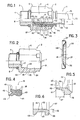
- - la figure 1 repésente une vue en élévation et en coupe partielle du dispositif de raccordement rapide conforme à l'invention et montée sur l'extrémité d'un tube ou tuyau
- - la figure 2 représente une vue en élévation et en coupe partielle du corps du dispositif de raccordement rapide
- - la figure 3 repésente une vue en élévation et en coupe de la rondelle de retenue constituant les moyens d'ancrage
- - la figure 4 représente une vue agrandie de la section d'un joint d'étanchéité
- - la figure 5 repésente une vue agrandie de la section de la bague formant les moyens dilatateurs
- - la figure 6 repésente une vue agrandie de la section de la bague supérieure de retenue.
- - Figure 1 shows an elevational view in partial section of the quick connection device according to the invention and mounted on the end of a tube or pipe
- - Figure 2 shows an elevational view in partial section of the body of the quick connection device
- - Figure 3 shows an elevational view in section of the retaining washer constituting the anchoring means
- - Figure 4 shows an enlarged view of the section of a seal
- - Figure 5 shows an enlarged view of the section of the ring forming the dilator means
- - Figure 6 shows an enlarged view of the section of the upper retaining ring.
Le dispositif de raccordement rapide 1 conforme à l'invention et représenté dans les figures 1 et 2 est destiné à être appliqué, soit sur un tube rigide, par exemple en acier, cuivre ou aluminium, sans préparation préalable des extrémités, soit sur un tube de nature souple ou semi-rigide en matériau synthétique, notamment, en polyamide.The quick connection device 1 according to the invention and shown in Figures 1 and 2 is intended to be applied either on a rigid tube, for example steel, copper or aluminum, without prior preparation of the ends, or on a tube flexible or semi-rigid in synthetic material, in particular in polyamide.
Ainsi, ce dispositif de raccordement rapide 1 comporte un corps 2 pourvu, à une extrémité 3, d'un embout fileté 4 et à l'autre extrémité 5 d'un six pans 6. Ce dernier sert, essentiellement, à visser l'embout fileté 4 dans un trou taraudé d'un raccord femelle non représenté dans les figures.Thus, this quick connection device 1 comprises a
Ledit corps 2 comporte, en outre, un alésage 7 débouchant, du côté de l'embout fileté 4, dans un orifice 8, de diamètre sensiblement égal au diamètre interne 9 de la conduite constituée par le tube ou tuyau 10 à l'extrémité 11 duquel il convient de rapporter le dispositif de raccordement rapide 1.Said
Dans cet alésage 7 de diamètre supérieur au diamètre 12 dudit tube ou tuyau 10 prennent place des moyens d'ancrage 13, des moyens dilatateurs 14, coopérant avec des moyens d'étanchéité 15 et une bague supérieure de retenue 16 assurant le maintien de ces différents éléments.In this
Par ailleurs, le dispositif de raccordement rapide 1 comporte une douille intérieure 17 comprenant, d'une part, un embout cylindrique 18 sur lequel est enfilée l'extrémité 11 du tube ou tuyau 10 et, d'autre part, une portée cylindrique 19 emmanchée par force dans l'alésage 7 du corps 2. Plus précisément, l'extrémité 20, orientée vers l'embout fileté 4 de cette douille intérieure 17 vient buter contre l'épaulement 21 situé dans l'alésage 7 et obtenu en raison de la différence du diamètre de ce dernier et de celui de l'orifice 8. Quant à l'autre extrémité 22 de cette douille intérieure 17, celle-ci est, de préférence, chanfreinée de manière à faciliter l'engagement de l'embout cylindrique 18 dans la partie interne 23 du tube ou tuyau 10.Furthermore, the quick connection device 1 comprises an inner bushing 17 comprising, on the one hand, a cylindrical end piece 18 on which the
Par ailleurs, l'alésage 7 présente un décrochement 24 permettant de définir un épaulement 25 contre lequel prennent appui les moyens d'ancrage 13 cités plus haut et représentés dans la figure 3. Préférentiellement, ceux-ci sont contitués, par une rondelle de retenue 26 formée par un anneau extérieur 27 de diamètre ajusté à celui de l'alésage 7, au niveau du décrochement 24, et dont le chant 28 coopère avec l'épaulement 25. Cet anneau extérieur 27 comporte, en outre, une pluralité de lamelles élastiques 29 sensiblement inclinées en direction de l'embout fileté 4. Ainsi, sous l'effet d'une traction exercée sur le tube ou tuyau 10, ces lamelles élastiques 29 sont amenées à s'incruster dans l'extrémité 11 de ce dernier et s'opposent à son dégagement du dispositif de raccordement rapide 1.Furthermore, the
Toutefois, pour s'assurer de l'efficacité des moyens d'ancrage 13, il est indispensable d'éviter tout coulissement de la rondelle de retenue 26 dans l'alésage 7 du corps 2. A cet effet, et selon une caractéristique de l'invention, l'alésage 7 présente, au niveau du décrochement 24 et à une distance de l'épaulement 25 légèrement supérieure à l'épaisseur de la rondelle de retenue 26, une rainure circulaire 30. Dans celle-ci est engagé un anneau élastique 31, dénommé encore circlips, coopérant avec le chant 32 de cette rondelle de retenue 26 et la maintenant en position dans l'alésage 7 en cas d'un effort exercé sur le tube ou tuyau 10 tendant à extraire celui-ci du dispositif de raccordement rapide 1. A noter que le diamètre interne de cet anneau élastique ou du circlips 31 est sensiblement supérieur au diamètre externe 12 du tube ou tuyau 10 de manière à définir avec ce dernier un espace annulaire 33.However, to ensure the effectiveness of the anchoring means 13, it is essential to avoid any sliding of the
Dans le but d'éviter que les lamelles élastiques 29 ne viennent à s'incruster dans le tube ou tuyau 10 à proximité immédiate du chant 34 de celui-ci, la portée cylindrique 19 de la douille intérieure 17 comporte sur sa face 36 un évidement circulaire 35 disposé dans le prolongement de l'embout cylindrique 18. Dans cet évidement circulaire 35 est insérée l'extrémité du tube ou tuyau 10 de manière à remédier au problème précité.In order to prevent the
Contre l'anneau élastique 31 sont appliqués des moyens dilatateurs 14 (voir figure 5) formés par une bague 37 ajustée au diamètre de l'alésage 7 au niveau du décrochement 24. Cette bague 37 présente une forme de coin au niveau de son chant 38 orienté vers les moyens d'étanchéité 15 et ayant pour office de provoquer la dilatation radiale de ces derniers.Against the
Préférentiellement, les moyens d'étanchéité 15 sont constitués, tels que représentés dans les figure 1 et 4, par un joint 39 pourvu d'un côté 40 de deux lèvres circulaires 41, 42, coopérant, respectivement, avec le pourtour externe 43 du tube ou tuyau 10 et la paroi de l'alésage 7 au niveau du décrochement 24. Ces lèvres 41, 42 respectent, entre elles, un angle leur permettant d'épouser intimement, la forme en coin du chant 38 de la bague 37 formant les moyens dilatateurs 14. Quant au joint 39, celui-ci est constitué subtantiellement, par un bourrelet torique 44 permettant d'obtenir une zone d'étanchéité supplémentaire entre l'alésage 7 du corps 2 et le tube ou tuyau 10.Preferably, the sealing means 15 are constituted, as shown in FIGS. 1 and 4, by a
On se réfère plus particulièrement aux figures 1 et 5.Reference is made more particularly to FIGS. 1 and 5.
Selon une caractéristique de l'invention, le dispositif de raccordement rapide 1 comporte des moyens 45 susceptibles d'agir sur la rondelle de retenue 26 constituant les moyens d'ancrage 13 afin d'annihiler leurs effets à l'égard du tube ou tuyau 10 pour, finalement, autoriser le retrait de ce dernier du corps 2.According to a characteristic of the invention, the quick connection device 1 comprises means 45 capable of acting on the retaining
Avantageusement, ces moyens 45 sont solidaires des moyens dilatateurs 14 et sont formés par une collerette cylindrique 46 aux dimensions définies par l'espace annulaire 33 délimité par l'anneau élastique 31 et le pourtour externe 43 du tube ou tuyau 10. Cette collerette cylindrique 46 est solidaire du chant 66, orienté vers l'embout fileté 4, de la bague 37. Ainsi, sous l'action d'une pression exercée sur cette dernière, ladite collerette cylindrique 46 est amenée à s'introduire dans l'espace annulaire 33 et à coopérer avec la rondelle de retenue 26 située de l'autre côté de l'anneau élastique 31. Pus exactement, la collerette cylindrique 46 coopère avec les lamelles élastiques 29 et provoque leur effacement de la périphérie externe 43 du tube ou tuyau 10. A noter que cette collerette cylindrique 46 comporte à son extrémité libre 60, un chanfrein 61 facilitant son insertion entre des lamelles élastiques 29 et le tube ou tuyau 10. Elle peut, également, présenter une forme légèrement tronconique contribuant à son efficacité.Advantageously, these means 45 are integral with the dilator means 14 and are formed by a
Préférentiellement, la longueur 47 de cette collerette cylindrique 46 est définie de sorte qu'elle ne dépasse pas l'extrémité libre 48 des lamelles élastiques 29, lorsque la bague 37 vient buter contre l'anneau élastique 31. Cette caractéristique permet de ramener ladite bague 37 dans sa position initiale après avoir retiré le tube ou tuyau 10 et, finalement, libérer les lamelles élastiques 29 afin de rendre le dispositif de raccordement rapide réutilisable.Preferably, the
Selon l'invention, le coulissement de la bague 37 et l'intervention des moyens 45 sur la rondelle de retenue 26, sont commandés par l'intermédiaire de la bague supérieure de retenue 16 venant en appui contre la face 49 du joint 39. Ainsi, cette bague supérieure de retenue 16 présente un diamètre légèrement inférieur à l'alésage 7 au niveau du décrochement 24 de manière à coulisser sur ce dernier. De plus, ladite bague supérieure de retenue 16, présente, sur son pourtour externe 62, un décrochement 50 définissant un épaulement 67 destiné à coopérer avec un sertissage 51 réalisé au niveau du corps 2 en sortie de l'alésage 7.According to the invention, the sliding of the
La fonction de ce sertissage 51 consiste à maintenir, dans l'alésage 7, essentiellement, les moyens d'étanchéité 15 et la bague supérieure de retenue 16. Il convient, en effet, de remarquer, d'une part, que les moyens d'ancrage 13 sont immobilisés par l'intermédiaire de l'anneau élastique 31 et d'autre part, que la douille intérieure 17 est engagée en force dans l'alésage 7. Par ailleurs, et selon un mode de réalisation préférentiel, la douille intérieure 17 et, notamment, sa portée cylindrique 19 est munie d'un rebord périphérique 52 venant s'insérer dans une rainure circulaire 53 usinée dans l'alésage 7. Cette caractéristique améliore considérablement la tenue mécanique de la douille intérieure 17 dans le corps 2. Cependant, dans ces conditions, il est nécessaire d'aménager dans l'alésage 7, au niveau de l'épaulement 25, une zone tronconique 63 facilitant l'emmanchement de la douille intérieure 17 et, notamment, l'engagement du rebord périphérique 52 dans la rainure circulaire 53 correspondante.The function of this crimping 51 consists in maintaining, in the
Ainsi, en raison, d'une part, de cette disposition particulière des différents éléments 13, 14, 15, 16, 17 dans l'alésage 7 et, d'autre part, de la propriété de la bague supérieure de retenue 16 de coulisser dans ce dernier, il est possible d'amener la collerette cylindrique 46 en position active et d'annihiler les effets des moyens d'ancrage 13 en appliquant une simple pression sur ladite bague supérieure de retenue 16 tentant à la repousser dans l'alésage 7. Dans ce but, cette bague supérieure de retenue 16 est prolongée, au niveau de son décrochement 50 par un élément tubulaire 55 émergeant sensiblement de l'alésage 7 du corps 2. Les dimensions de cet élément tubulaire 55 et, notamment, son diamètre intérieur et l'épaisseur de sa paroi 56 sont déterminées en fonction de l'espace annulaire 64 délimité par le sertissage 51 et le pourtour externe 43 du tube ou tuyau 10. Etant donné que ladite paroi 56 présente, nécessairement, une épaisseur 65 réduite, l'élément tubulaire 55 comporte à son extrémité libre 57 un renfort 58 formé par un bourrelet ou rebord périphérique. Sur ce dernier peut être appliqué l'outil destiné à repousser la bague supérieure de retenue 16 dans l'alésage 7. Cette pression est, initialement, répercutée sur les moyens d'étanchéité 15 provoquant le coulissement des moyens dilatateurs dans l'alésage 7 et, finalement, le détachement des moyens d'ancrage 13 du tube ou tuyau 10.Thus, due, on the one hand, to this particular arrangement of the
L'avantage incontestable d'un tel dispositif de raccordement rapide 1, réside dans son utilisation possible à des pressions élevés tout en étant démontable, en un minimum de temps, au moyen d'un outillage classique.The indisputable advantage of such a quick connection device 1 lies in its possible use at high pressures while being removable, in a minimum of time, using conventional tools.
Claims (8)
Applications Claiming Priority (2)
| Application Number | Priority Date | Filing Date | Title |
|---|---|---|---|
| FR8803156A FR2628505B1 (en) | 1988-03-08 | 1988-03-08 | QUICK CONNECTION DEVICE FOR HYDRAULIC CIRCUIT |
| FR8803156 | 1988-03-08 |
Publications (1)
| Publication Number | Publication Date |
|---|---|
| EP0336866A1 true EP0336866A1 (en) | 1989-10-11 |
Family
ID=9364162
Family Applications (1)
| Application Number | Title | Priority Date | Filing Date |
|---|---|---|---|
| EP89440020A Withdrawn EP0336866A1 (en) | 1988-03-08 | 1989-03-02 | Detachable pipe joint |
Country Status (4)
| Country | Link |
|---|---|
| EP (1) | EP0336866A1 (en) |
| DE (1) | DE336866T1 (en) |
| ES (1) | ES2012316A4 (en) |
| FR (1) | FR2628505B1 (en) |
Cited By (4)
| Publication number | Priority date | Publication date | Assignee | Title |
|---|---|---|---|---|
| EP0459713A2 (en) * | 1990-05-24 | 1991-12-04 | Shigeru Suzuki | Pipe connector |
| GB2304390A (en) * | 1995-08-15 | 1997-03-19 | Opella Ltd | Tube coupling with toothed retaining ring |
| FR2777341A1 (en) * | 1998-04-08 | 1999-10-15 | Comap | Instantaneous quick-fit type connector for pipework e.g. water, central heating |
| WO2021042214A1 (en) * | 2019-09-05 | 2021-03-11 | 9352-4585 Québec Inc. | Plumbing fitting |
Citations (7)
| Publication number | Priority date | Publication date | Assignee | Title |
|---|---|---|---|---|
| DE1988017U (en) * | 1966-01-21 | 1968-06-20 | Pneumelec S A | DEVICE FOR CONNECTING A PIPE. |
| US4123090A (en) * | 1976-07-19 | 1978-10-31 | Imperial-Eastman Corporation | Push-pull fitting |
| GB2060106A (en) * | 1979-10-10 | 1981-04-29 | Britton Ltd C E & J P | Quick Release Tube Coupling |
| GB2160279A (en) * | 1984-06-13 | 1985-12-18 | Hawke Cable Glands Ltd | Releasable pipe coupling |
| FR2578306A1 (en) * | 1985-01-03 | 1986-09-05 | Anoflex Flexibles | Rapid connection for pressurised fluids circuits |
| FR2582771A2 (en) * | 1985-05-31 | 1986-12-05 | Anoflex Flexibles | Rapid connection for pressurised fluid circuits |
| FR2591309A1 (en) * | 1985-12-11 | 1987-06-12 | Capri Codec Sa | Hydraulic connector with rapid manual connection for a fluid pipeline |
-
1988
- 1988-03-08 FR FR8803156A patent/FR2628505B1/en not_active Expired - Lifetime
-
1989
- 1989-03-02 ES ES89440020T patent/ES2012316A4/en active Pending
- 1989-03-02 EP EP89440020A patent/EP0336866A1/en not_active Withdrawn
- 1989-03-02 DE DE1989440020 patent/DE336866T1/en active Pending
Patent Citations (7)
| Publication number | Priority date | Publication date | Assignee | Title |
|---|---|---|---|---|
| DE1988017U (en) * | 1966-01-21 | 1968-06-20 | Pneumelec S A | DEVICE FOR CONNECTING A PIPE. |
| US4123090A (en) * | 1976-07-19 | 1978-10-31 | Imperial-Eastman Corporation | Push-pull fitting |
| GB2060106A (en) * | 1979-10-10 | 1981-04-29 | Britton Ltd C E & J P | Quick Release Tube Coupling |
| GB2160279A (en) * | 1984-06-13 | 1985-12-18 | Hawke Cable Glands Ltd | Releasable pipe coupling |
| FR2578306A1 (en) * | 1985-01-03 | 1986-09-05 | Anoflex Flexibles | Rapid connection for pressurised fluids circuits |
| FR2582771A2 (en) * | 1985-05-31 | 1986-12-05 | Anoflex Flexibles | Rapid connection for pressurised fluid circuits |
| FR2591309A1 (en) * | 1985-12-11 | 1987-06-12 | Capri Codec Sa | Hydraulic connector with rapid manual connection for a fluid pipeline |
Cited By (5)
| Publication number | Priority date | Publication date | Assignee | Title |
|---|---|---|---|---|
| EP0459713A2 (en) * | 1990-05-24 | 1991-12-04 | Shigeru Suzuki | Pipe connector |
| EP0459713A3 (en) * | 1990-05-24 | 1992-05-27 | Fujine Sangyo Company Limited | Pipe connector |
| GB2304390A (en) * | 1995-08-15 | 1997-03-19 | Opella Ltd | Tube coupling with toothed retaining ring |
| FR2777341A1 (en) * | 1998-04-08 | 1999-10-15 | Comap | Instantaneous quick-fit type connector for pipework e.g. water, central heating |
| WO2021042214A1 (en) * | 2019-09-05 | 2021-03-11 | 9352-4585 Québec Inc. | Plumbing fitting |
Also Published As
| Publication number | Publication date |
|---|---|
| DE336866T1 (en) | 1990-05-03 |
| FR2628505A1 (en) | 1989-09-15 |
| FR2628505B1 (en) | 1990-05-18 |
| ES2012316A4 (en) | 1990-03-16 |
Similar Documents
| Publication | Publication Date | Title |
|---|---|---|
| EP2878873B1 (en) | Cartridge-type quick-coupling device | |
| FR2847646A1 (en) | Tube joint for connecting a tube to fluid operated apparatus has annular projection provided at the end surface of the nut and which is screwed to the joint body to regulate the screwing amount of the nut on the joint body | |
| CA2321137A1 (en) | System for connecting one end of a conduit to a body | |
| EP0406145A1 (en) | Seal assembly for locked sealed joints | |
| FR2736988A1 (en) | TUBE CONNECTION | |
| EP2817548B1 (en) | Sealed-coupling device without a retention area | |
| FR2810087A1 (en) | Insert for implanting pipe connection in tapped housing comprises body which fits against tapped section, on which rings with anchor lugs are mounted, each lug being compressible from position above outer surface of insert to below it | |
| WO2004023013A2 (en) | Method for connecting pipes for high pressure fluids | |
| FR2675234A1 (en) | Corrosion-proof sleeve for a drilling made in a metal pipe, and tool for fitting this sleeve | |
| FR2591309A1 (en) | Hydraulic connector with rapid manual connection for a fluid pipeline | |
| EP0336866A1 (en) | Detachable pipe joint | |
| EP2309164B1 (en) | Quick coupling device with inverted guiding and sealing zones | |
| EP0187608B1 (en) | Coupling of the quick-acting type for pressurized-fluid systems whereby the pressure can reach one hundred and fifty bar | |
| FR2938038A1 (en) | SEALING ELEMENT WITHOUT RETENTION AREA AND CONNECTING DEVICE COMPRISING SUCH A SEALING ELEMENT | |
| FR2578621A1 (en) | End connector for semi-stiff plastics pipe | |
| WO2000050800A1 (en) | Connection device for connecting a pipe end to an element | |
| EP3280942A1 (en) | Connecting device having a movable seal for chamfered tube | |
| EP1522356A1 (en) | Sealed coupling device for a tube with a threaded extension section | |
| FR2806779A1 (en) | METHOD FOR ASSEMBLING A CONDUIT ON A RIGID TUBULAR END CAP BY MEANS OF A NUT SCREWED ONTO THE END CAP, AND CONNECTION FOR IMPLEMENTING THE METHOD | |
| EP0046705A1 (en) | Joint for fluid under pressure between a plastics pipe and a metal pipe | |
| FR2938625A1 (en) | CONNECTING DEVICE HAVING REVERSE SEALING AND HITCHING ZONES. | |
| FR2769350A1 (en) | Process for joining flexible hose to tubular connector | |
| EP1139002A1 (en) | Method for disconnecting the end of conduit from a connector and connecting device therefor | |
| EP0765991A1 (en) | Method and device for connecting two concrete elements | |
| FR2480900A3 (en) | Threaded spigot fitting internally reinforced rubber hose - uses radially stepped steel sleeve screwing onto stripped hose end containing brass bore liner |
Legal Events
| Date | Code | Title | Description |
|---|---|---|---|
| PUAI | Public reference made under article 153(3) epc to a published international application that has entered the european phase |
Free format text: ORIGINAL CODE: 0009012 |
|
| AK | Designated contracting states |
Kind code of ref document: A1 Designated state(s): AT BE CH DE ES GB GR IT LI LU NL SE |
|
| 17P | Request for examination filed |
Effective date: 19891102 |
|
| ITCL | It: translation for ep claims filed |
Representative=s name: BUGNION S.P.A. |
|
| GBC | Gb: translation of claims filed (gb section 78(7)/1977) | ||
| TCAT | At: translation of patent claims filed | ||
| TCNL | Nl: translation of patent claims filed | ||
| DET | De: translation of patent claims | ||
| 17Q | First examination report despatched |
Effective date: 19910403 |
|
| STAA | Information on the status of an ep patent application or granted ep patent |
Free format text: STATUS: THE APPLICATION IS DEEMED TO BE WITHDRAWN |
|
| 18D | Application deemed to be withdrawn |
Effective date: 19910814 |