EP0337429A2 - Ink jet head - Google Patents
Ink jet head Download PDFInfo
- Publication number
- EP0337429A2 EP0337429A2 EP89106516A EP89106516A EP0337429A2 EP 0337429 A2 EP0337429 A2 EP 0337429A2 EP 89106516 A EP89106516 A EP 89106516A EP 89106516 A EP89106516 A EP 89106516A EP 0337429 A2 EP0337429 A2 EP 0337429A2
- Authority
- EP
- European Patent Office
- Prior art keywords
- gap
- ink
- vibrator
- area
- nozzle
- Prior art date
- Legal status (The legal status is an assumption and is not a legal conclusion. Google has not performed a legal analysis and makes no representation as to the accuracy of the status listed.)
- Granted
Links
- 239000000758 substrate Substances 0.000 claims abstract description 46
- 238000013016 damping Methods 0.000 abstract description 14
- 230000000737 periodic effect Effects 0.000 abstract description 10
- 238000010276 construction Methods 0.000 description 14
- 125000006850 spacer group Chemical group 0.000 description 10
- 238000006073 displacement reaction Methods 0.000 description 6
- 230000001276 controlling effect Effects 0.000 description 3
- 230000000875 corresponding effect Effects 0.000 description 3
- 230000000694 effects Effects 0.000 description 3
- 238000005323 electroforming Methods 0.000 description 3
- 239000012943 hotmelt Substances 0.000 description 3
- 230000005499 meniscus Effects 0.000 description 3
- 238000005452 bending Methods 0.000 description 2
- 230000003247 decreasing effect Effects 0.000 description 2
- 230000002542 deteriorative effect Effects 0.000 description 2
- 230000005684 electric field Effects 0.000 description 2
- 230000002708 enhancing effect Effects 0.000 description 2
- 239000012530 fluid Substances 0.000 description 2
- 238000004519 manufacturing process Methods 0.000 description 2
- 235000008504 concentrate Nutrition 0.000 description 1
- 239000012141 concentrate Substances 0.000 description 1
- 239000004020 conductor Substances 0.000 description 1
- 230000008602 contraction Effects 0.000 description 1
- 238000004512 die casting Methods 0.000 description 1
- 239000000428 dust Substances 0.000 description 1
- 238000005265 energy consumption Methods 0.000 description 1
- 230000007613 environmental effect Effects 0.000 description 1
- 238000005530 etching Methods 0.000 description 1
- 239000012212 insulator Substances 0.000 description 1
- 238000000034 method Methods 0.000 description 1
- 238000000059 patterning Methods 0.000 description 1
- 230000002093 peripheral effect Effects 0.000 description 1
- 229910000679 solder Inorganic materials 0.000 description 1
- 239000007787 solid Substances 0.000 description 1
- 230000002463 transducing effect Effects 0.000 description 1
- 230000003245 working effect Effects 0.000 description 1
Images


Classifications
-
- B—PERFORMING OPERATIONS; TRANSPORTING
- B41—PRINTING; LINING MACHINES; TYPEWRITERS; STAMPS
- B41J—TYPEWRITERS; SELECTIVE PRINTING MECHANISMS, i.e. MECHANISMS PRINTING OTHERWISE THAN FROM A FORME; CORRECTION OF TYPOGRAPHICAL ERRORS
- B41J2/00—Typewriters or selective printing mechanisms characterised by the printing or marking process for which they are designed
- B41J2/005—Typewriters or selective printing mechanisms characterised by the printing or marking process for which they are designed characterised by bringing liquid or particles selectively into contact with a printing material
- B41J2/01—Ink jet
- B41J2/135—Nozzles
- B41J2/16—Production of nozzles
- B41J2/1607—Production of print heads with piezoelectric elements
- B41J2/1614—Production of print heads with piezoelectric elements of cantilever type
-
- B—PERFORMING OPERATIONS; TRANSPORTING
- B41—PRINTING; LINING MACHINES; TYPEWRITERS; STAMPS
- B41J—TYPEWRITERS; SELECTIVE PRINTING MECHANISMS, i.e. MECHANISMS PRINTING OTHERWISE THAN FROM A FORME; CORRECTION OF TYPOGRAPHICAL ERRORS
- B41J2/00—Typewriters or selective printing mechanisms characterised by the printing or marking process for which they are designed
- B41J2/005—Typewriters or selective printing mechanisms characterised by the printing or marking process for which they are designed characterised by bringing liquid or particles selectively into contact with a printing material
- B41J2/01—Ink jet
- B41J2/135—Nozzles
- B41J2/14—Structure thereof only for on-demand ink jet heads
- B41J2/14201—Structure of print heads with piezoelectric elements
- B41J2/14282—Structure of print heads with piezoelectric elements of cantilever type
-
- B—PERFORMING OPERATIONS; TRANSPORTING
- B41—PRINTING; LINING MACHINES; TYPEWRITERS; STAMPS
- B41J—TYPEWRITERS; SELECTIVE PRINTING MECHANISMS, i.e. MECHANISMS PRINTING OTHERWISE THAN FROM A FORME; CORRECTION OF TYPOGRAPHICAL ERRORS
- B41J2/00—Typewriters or selective printing mechanisms characterised by the printing or marking process for which they are designed
- B41J2/005—Typewriters or selective printing mechanisms characterised by the printing or marking process for which they are designed characterised by bringing liquid or particles selectively into contact with a printing material
- B41J2/01—Ink jet
- B41J2/135—Nozzles
- B41J2/16—Production of nozzles
- B41J2/162—Manufacturing of the nozzle plates
-
- B—PERFORMING OPERATIONS; TRANSPORTING
- B41—PRINTING; LINING MACHINES; TYPEWRITERS; STAMPS
- B41J—TYPEWRITERS; SELECTIVE PRINTING MECHANISMS, i.e. MECHANISMS PRINTING OTHERWISE THAN FROM A FORME; CORRECTION OF TYPOGRAPHICAL ERRORS
- B41J2/00—Typewriters or selective printing mechanisms characterised by the printing or marking process for which they are designed
- B41J2/005—Typewriters or selective printing mechanisms characterised by the printing or marking process for which they are designed characterised by bringing liquid or particles selectively into contact with a printing material
- B41J2/01—Ink jet
- B41J2/135—Nozzles
- B41J2/16—Production of nozzles
- B41J2/1621—Manufacturing processes
- B41J2/1623—Manufacturing processes bonding and adhesion
-
- B—PERFORMING OPERATIONS; TRANSPORTING
- B41—PRINTING; LINING MACHINES; TYPEWRITERS; STAMPS
- B41J—TYPEWRITERS; SELECTIVE PRINTING MECHANISMS, i.e. MECHANISMS PRINTING OTHERWISE THAN FROM A FORME; CORRECTION OF TYPOGRAPHICAL ERRORS
- B41J2/00—Typewriters or selective printing mechanisms characterised by the printing or marking process for which they are designed
- B41J2/005—Typewriters or selective printing mechanisms characterised by the printing or marking process for which they are designed characterised by bringing liquid or particles selectively into contact with a printing material
- B41J2/01—Ink jet
- B41J2/135—Nozzles
- B41J2/16—Production of nozzles
- B41J2/1621—Manufacturing processes
- B41J2/1625—Manufacturing processes electroforming
-
- B—PERFORMING OPERATIONS; TRANSPORTING
- B41—PRINTING; LINING MACHINES; TYPEWRITERS; STAMPS
- B41J—TYPEWRITERS; SELECTIVE PRINTING MECHANISMS, i.e. MECHANISMS PRINTING OTHERWISE THAN FROM A FORME; CORRECTION OF TYPOGRAPHICAL ERRORS
- B41J2/00—Typewriters or selective printing mechanisms characterised by the printing or marking process for which they are designed
- B41J2/005—Typewriters or selective printing mechanisms characterised by the printing or marking process for which they are designed characterised by bringing liquid or particles selectively into contact with a printing material
- B41J2/01—Ink jet
- B41J2/135—Nozzles
- B41J2/16—Production of nozzles
- B41J2/1621—Manufacturing processes
- B41J2/1626—Manufacturing processes etching
-
- B—PERFORMING OPERATIONS; TRANSPORTING
- B41—PRINTING; LINING MACHINES; TYPEWRITERS; STAMPS
- B41J—TYPEWRITERS; SELECTIVE PRINTING MECHANISMS, i.e. MECHANISMS PRINTING OTHERWISE THAN FROM A FORME; CORRECTION OF TYPOGRAPHICAL ERRORS
- B41J2/00—Typewriters or selective printing mechanisms characterised by the printing or marking process for which they are designed
- B41J2/005—Typewriters or selective printing mechanisms characterised by the printing or marking process for which they are designed characterised by bringing liquid or particles selectively into contact with a printing material
- B41J2/01—Ink jet
- B41J2/135—Nozzles
- B41J2/16—Production of nozzles
- B41J2/1621—Manufacturing processes
- B41J2/164—Manufacturing processes thin film formation
- B41J2/1643—Manufacturing processes thin film formation thin film formation by plating
-
- B—PERFORMING OPERATIONS; TRANSPORTING
- B41—PRINTING; LINING MACHINES; TYPEWRITERS; STAMPS
- B41J—TYPEWRITERS; SELECTIVE PRINTING MECHANISMS, i.e. MECHANISMS PRINTING OTHERWISE THAN FROM A FORME; CORRECTION OF TYPOGRAPHICAL ERRORS
- B41J2/00—Typewriters or selective printing mechanisms characterised by the printing or marking process for which they are designed
- B41J2/005—Typewriters or selective printing mechanisms characterised by the printing or marking process for which they are designed characterised by bringing liquid or particles selectively into contact with a printing material
- B41J2/01—Ink jet
- B41J2/135—Nozzles
- B41J2/14—Structure thereof only for on-demand ink jet heads
- B41J2002/14387—Front shooter
-
- B—PERFORMING OPERATIONS; TRANSPORTING
- B41—PRINTING; LINING MACHINES; TYPEWRITERS; STAMPS
- B41J—TYPEWRITERS; SELECTIVE PRINTING MECHANISMS, i.e. MECHANISMS PRINTING OTHERWISE THAN FROM A FORME; CORRECTION OF TYPOGRAPHICAL ERRORS
- B41J2/00—Typewriters or selective printing mechanisms characterised by the printing or marking process for which they are designed
- B41J2/005—Typewriters or selective printing mechanisms characterised by the printing or marking process for which they are designed characterised by bringing liquid or particles selectively into contact with a printing material
- B41J2/01—Ink jet
- B41J2/135—Nozzles
- B41J2/14—Structure thereof only for on-demand ink jet heads
- B41J2002/14475—Structure thereof only for on-demand ink jet heads characterised by nozzle shapes or number of orifices per chamber
Definitions
- the present invention relates to an ink jet recording apparatus for forming an ink image on a medium such as recording paper or the like by ejecting ink droplets onto the medium. More particularly, the present invention relates to the ink jet head of such an ink jet recording apparatus.
- An ink jet head having a substrate in which a plurality of nozzles are formed and a piezoelectric transducer for pressurizing and ejecting ink is disclosed in US-A-4,072,959.
- vibrators forming the piezoelectric transducer are displaced almost rectangularly to the nozzle forming substrate so that the ink passage to the nozzles is short and the discharge efficiency and stability of ink droplets are high.
- the ink passages between the nozzles communicate with each other at a short distance, bubbles and foreign matters like dust and the like which may be mixed in the ink will not influence the normal operation.
- the vibrators being of a cantilever or center beam structure, provide a high electro-mechanical transducing efficiency and allow to achieve the necessary vibrator displacement by a low voltage.
- the present invention is intended to remedy the above mentioned problems and to realize an ink jet head having a high energy efficiency and stable characteristics while providing a good ejection rate, ejection quantity and ejection recover time of the ink droplets at the same time.
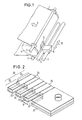
- Fig. 1 illustrates one embodiment of a recording apparatus having an ink jet head according to the invention mounted thereon.
- a recording medium 1 is wound around a platen 4 under the pressure of feed rollers 2 and 3, and is fed in the direction indicated by an arrow 5 during the recording.
- An ink jet head 9 is mounted on a carriage 8 shiftable in the direction of an arrow 10 parallel to the platen 4 along guide shafts 6, 7.
- the ink jet head 9 has a plurality of nozzles (not shown in Fig. 1) which can be independently controlled to eject ink droplets.
- the ink jet head 9 is moved in the direction of an arrow 10 while ink droplets are selectively ejected by its nozzles, and thereby an ink image is formed on the recording medium 1.
- Fig. 2 is a perspective view showing the construction of a piezoelectric transducer that can be used in the ink jet head of the present invention.
- the transducer 20 comprises a plurality of vibrators 21, separated by cuts 23 from each other, and a fixed portion 22.
- Signal electrodes 25 consisting of an Au thin layer are formed on one side of respective piezoelectric elements 24 consisting of PZT.
- a metallic plate consisting of an Ni layer is formed as a common electrode 26 on the other side of the piezoelectric elements 24.
- a spacer 27 consisting of an Ni layer is formed on the fixed portion 22.
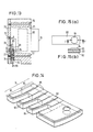
- Fig. 3(a) is a front view illustrating the shape of a nozzle forming substrate of the present invention.
- Fig. 3(b) is a sectional view of the nozzle forming portion along line A-A in Fig. 3(a).
- the nozzle forming substrate 30 is made of an Ni thin plate having a plurality of nozzles 31 formed by electroforming. Portions other than a belt-like portion linking neighboring portions of nozzle inlet openings 34 are removed by etching. A level difference is thus provided forming a bed 32 in the neighborhood of the nozzle inlet openings 34 of the nozzle forming substrate.
- Fig. 4 is a partial sectional view showing the construction of the ink jet head 9 according to the first embodiment of the present invention.
- the nozzle forming substrate 30, the piezoelectric transducer 20 and an elastic seat 42 are arranged between a main frame 40 and a subframe 41.
- the subframe 41 has an ink reservoir 43 formed therein and ink (not indicated) is fed from the ink reservoir 43 to the nozzles 31.
- the direction into which the piezoelectric element 24 is polarized is such that the direction of contraction is orthogonal to the electric field established when a voltage is applied between the common electrode 26 and the signal electrode 25.
- the Ni thin layer forming the common electrode 26 has a high elastic modulus, when an electric field is applied to the piezoelectric element, a bending moment is generated toward the signal electrode 25 resulting in a corresponding deformation. Therefore, when a voltage is applied in standby condition and selectively removed, the free end of the vibrator 21 is deformed and displaced towards the nozzle forming substrate 30 to eject ink through the nozzle 31.
- a gap a between the vibrator 21 and the nozzle 31 is dimensioned so as to obtain a better ink ejection characteristic, and a gap b between the vibrator 21 and the portions of the substrate 30 other than the bed 32 of the nozzle inlet openings 34 (Fig. 3(a)) is set so as to operate the vibrator in a proper periodic damping range in order to achieve a smooth feed of ink.
- a peak pressure is generated near the center of the disk and no pressure is generated at the peripheral edge portion.
- the value of the pressure depends largely on the distance h between the disks.
- an efficient ejection may be realized by controlling voids in the neighborhood of the nozzles and also controlling voids in other areas independently from each other.
- the gap in the second area will be set so as to control the flow resistance and mass load acting on the vibrator by the ink flow caused by a displacement of the vibrator.
- an appropriate periodic damping characteristic of the vibrator can be set. If the gap is larger than an appropriate value, a residual vibration inhibits a high-speed response and further, a plurality of ink drop lets are ejected upon a single driving signal (displacement of the vibrator).
- the flow resistance load will become excessive and a large power will be required for the displacement. It was found experimentally that the flow resistance load in the second area must be decreased if the ink viscosity is more than 5mPas, and thus a ⁇ b is preferable. If the ink viscosity is 5mPas or less, it is desirable that an appropriate flow resistance load be provided in the second area, and thus a > b will be preferable.
- Figs. 6(a), (b) to 9(a), (b) are front views illustrating various shapes of the nozzle forming substrate for the ink jet head according to the invention, and sectional views along lines B-B, C-C, D-D, E-E, respectively.
- the shapes shown in Fig. 6 are intended to enhance the ink feed to the nozzles from all circumferential directions by giving a circular shape to the bed 32 of a nearby portion to the inlet opening 34 of each nozzle 31 as compared to the belt-like bed 32 shown in Fig. 3(a).
- the arrangements shown in Figs. 7 to 9 differ from that shown in Fig. 6 in that grooves 33 are provided to extend radially from the nozzle center, thereby further enhancing the ink feed.
- Figs. 7 and 9 are effective in reducing the mutual influence among the nozzles, since grooves 33 are not provided in portions of the bed 32 opposing adjacent nozzles.
- the area of the nozzle inlet opening 34 is wider than that of the outlet opening and thus, the nozzle is horn-like in section.
- the nozzle shape is not particularly limited to this specific shape and it is apparent that other shapes may be employed for the nozzle in the invention.
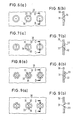
- Fig. 10 shows another embodiment of the ink jet head using a vibrator form different from that of the previous embodiment.
- the basic construction is similar to the foregoing embodiment and thus, the following description will concentrate on the differences.
- a vibrator 52 is disposed opposite to each nozzle 53 through an infinitesimal gap a near to its free end.
- a wiring 55 is connected to signal electrodes 54 to selectively apply a voltage to the vibrators.
- each vibrator has a gap controlling layer 57 on a front nose portion.
- FIG. 12 shows a partial sectional view of a third embodiment of the ink jet head according to the invention.
- a nozzle forming substrate 60 comprises a metallic thin plate having a plurality of nozzles 61 formed therein and a portion around the nozzle opposite to the free end of a vibrator 62 is formed to be thicker than other portions.
- a vibrator 62 is disposed opposite to each nozzle 61 through an infinitesimal gap a near to the free end of the vibrator.
- a groove 64 is formed in a portion of the nozzle forming substrate 60 opposite to the neighborhood of a fixed end of the vibrator 62. Accordingly, the gap b in the neighborhood of the fixed end of the vibrator and the gap a in the neighborhood of the free end of the vibrator are determined by the thickness of a spacer 65 and the depth of the groove 64. Again, the gap b is determined to obtain a desired periodic damping of the vibrator 62 and the gap a to obtain the necessary ink ejection.
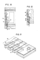
- Fig. 13 is a sectional view of the ink jet head according to a fourth embodiment of the invention.
- a nozzle forming plate 72, a spacer 73, a piezoelectric transducer 74 and an elastic seat 75 are arranged between a main frame 70 and a subframe 71, fixed together by means of setscrews 76, 77.
- the nozzle forming plate 72 comprises a metallic thin plate having a plurality of nozzles 78 formed therein.
- a heater 79 is mounted on the rear side of the subframe 71 and used to heat the ink jet head up to a working temperature and to dissolve a hot-melt ink (not shown) filled in an ink reservoir 80 and around the piezoelectric transducer 74.
- the ink has a solid state at room temperature.
- Fig. 14 is a perspective view of the piezoelectric transducer 74. It comprises a plurality of vibrators 81, separated by cuts and a fixed portion 82.
- a piezoelectric element 83 consisting of PZT has a signal electrode 84 consisting of an Au thin layer on one side and a common electrode 85 consisting of an Ni thin layer on the other side.
- the piezoelectric element 83 and the common electrode 85 are joined together by means of a solder (having a fusing point of 140°C) at a temperature of 160°C which is higher than the aforementioned working temperature.
- the piezoelectric transducer 74 is tightly fixed on the nozzle plate so as to keep the tangent of the fixed end of the vibrator 81 in parallel with the nozzle plate 72.
- the free end of the vibrator 81 is disposed opposite to a corresponding nozzle 78 through an infinitesimal gap near the free end, which is produced by the warp.
- the piezoelectric transducer 74 has its fixed end clamped between the main frame 70 and the subframe 71 through the spacer 73 and the elastic seat 75.
- the piezoelectric transducer 74 thus remains flat in this area and an internal stress is generated as a consequence.
- the vibrator is designed with a relatively short fixed end so that the internal stress does not exceed a permissible range, and thereby a damage of the vibrator is prevented.
- a wiring 86 is connected to the individual signal electrodes 84 in order to selectively energize the vibrators.
- the common electrodes 85 are independently formed on each vibrator and electrically connected with each other by using Ni for the spacer 73 and an Al or Zn die casting for the main frame 70.
- a hot-melt ink is fed around the nozzles from the ink reservoir 80.
- the nose of the vibrator is displaced and ink ejected from the nozzle 78.
- the gap b for setting an appropriate periodic damping of the vibrator 81 is determined by the thickness of the spacer 73.
- a warp y is produced on the free end of the vibrator 81 according to the bimetal effect explained above. Therefore, the gap a between the nozzle and the neighborhood of the free end of the vibrator, necessary for ejecting ink is secured by clamping the fixed end of the vibrator 81 onto the nozzle forming plate 72 through the spacer 73.
- Fig. 17(a), (b) to Fig. 19(a), (b) are drawings corresponding to Fig. 15(a), (b) and showing alternative constructions of the vibrators.
- grooves 96 are provided in the circular projection 94 in order to further enhance the ink feed.
- the grooves 96 extend radially from the nozzle center and their bottom is on the same plane as the portions other than the projection 94.
- the alternatives shown in Figs. 17 and 19 are not provided with grooves 96 on both sides facing to adjacent vibrators, thereby to decrease a mutual influence between the nozzles.
- an electrolyticly plated layer 203 is formed on a master having a conductor pattern 202 formed on an insulator 201.
- the layer 203 is coated with a resist layer 204 and an electrolyticly plated layer 205 is further formed on portions of the layer 202 exposed through patterning.
- a die having a desired nozzle hole and a suitable level difference is obtained by electroforming.
- An electrolyticly plated layer is formed on the die and thereafter removed from the die to obtain the stepped nozzle forming substrate shown in Fig. 20.
- this nozzle forming substrate results in a gap of width a in a first area and a gap of width b in the remaining second area between the nozzle forming substrate and the vibrator.
- this nozzle forming substrate results in a gap of width a in a first area and a gap of width b in the remaining second area between the nozzle forming substrate and the vibrator.
- Figs. 21(a), (b) are a front view and a sectional view, similar to Figs. 20(a), (b), showing the relation between the vibrator and the nozzle forming substrate of a seventh embodiment.
- the same reference numerals as in Figs. 20(a), (b) are used.
- the seventh embodiment is intended for the case where the viscosity of the ink is low.
- the nozzle forming substrate In a circular shaped first area of radius c in the neighborhood of the nozzle, the nozzle forming substrate has a recess resulting in a gap width a which is larger than the gap width b in the remaining area of the gap between the nozzle forming substrate and the vibrator.
- the gap between the nozzle forming substrate and the vibrator is divided into a first area near to a nozzle inlet opening of the nozzle forming substrate and a remaining second area.
- the gap width in the first area is different from that in the second area.
- the width a of the gap in the first area has a value necessary for the ink ejection.
- the gap width b in the second area providing a feed passage for the ink is selected so as to allow a quick restoration of a nozzle meniscus after ejection of an ink droplet.
- the time for the ink to be refilled is controlled to a proper value. Thereby, the recover time can be shortened while keeping the ink droplet ejection rate and the ejection quantity at desired values.
- the present invention provides an ink jet head superior in performance by improving various characteristics such as ink droplet ejection rate, ejection quantity, ejection recover time and ejection stability and the like at the same time.
- the gap width between the vibrator and the nozzle forming substrate in the said second area can be set to a value allowing the vibrator to operate in an appropriate periodic damping range, the energy consumption due to the viscosity of the ink existing in the gap between the vibrator and the nozzle forming substrate will be decreased allowing an operation at a relatively low driving voltage. Since the gap width of the first area and the second area can be set independently, a margin for setting each width will be expanded, thereby enhancing the production yield.
Abstract
Description
- The present invention relates to an ink jet recording apparatus for forming an ink image on a medium such as recording paper or the like by ejecting ink droplets onto the medium. More particularly, the present invention relates to the ink jet head of such an ink jet recording apparatus.
- An ink jet head having a substrate in which a plurality of nozzles are formed and a piezoelectric transducer for pressurizing and ejecting ink is disclosed in US-A-4,072,959. In this prior art ink jet head, vibrators forming the piezoelectric transducer are displaced almost rectangularly to the nozzle forming substrate so that the ink passage to the nozzles is short and the discharge efficiency and stability of ink droplets are high. Further, since the ink passages between the nozzles communicate with each other at a short distance, bubbles and foreign matters like dust and the like which may be mixed in the ink will not influence the normal operation.
- The vibrators, being of a cantilever or center beam structure, provide a high electro-mechanical transducing efficiency and allow to achieve the necessary vibrator displacement by a low voltage.
- On the other hand, stable characteristics are hard to obtain with the aforementioned prior art. The size of a gap between each vibrator and the nozzle forming substrate influences characteristics like the ejection rate, the ejection quantity and the ejection recover time. Therefore, in order to obtain satisfying characteristics, the gap size must be controlled with a very small tolerance. To increase the ejection rate and the ejection quantity of the ink droplets it is necessary to keep the gap between the nozzle forming substrate and the vibrator disposed opposite to it within an infinitesimal constant range, so as to increase the pressure of the ink existing near to the nozzles. However, in such infinitesimal gap, a great flow induced resistance due to a flow of the ink existing in the gap between the vibrator and the nozzle forming substrate, opposes the vibrator displacement. Also, it is difficult to set a proper damping condition of the vibrators, and thus, for example, if the damping is excessive, the maximum value of the ink ejection pressure is minimized and the time required for reaching the maximum ejection pressure becomes long compared to the case of a lower periodic damping with a long time constant, thus deteriorating the energy efficiency. Moreover, the feed of the ink necessary for restoring a nozzle meniscus for the next ink ejection is hindered by the small gap between the vibrator and the nozzle forming substrate, so that the time for ink return becomes long deteriorating the recover time and making a phenomenon of an ejection quantity fluctuation unavoidable, depending on the driving frequency.
- The present invention is intended to remedy the above mentioned problems and to realize an ink jet head having a high energy efficiency and stable characteristics while providing a good ejection rate, ejection quantity and ejection recover time of the ink droplets at the same time.
- This object is achieved with an ink jet head as claimed.
- With this solution, when the vibrator is deformed and displaced to eject ink, an ejection pressure generation cha racteristic and a periodic damping characteristic depending on the flow resistance acting on the ink existing between the nozzle forming substrate and the vibrator moving part, can be controlled independently from each other, thus allowing to realize a head with stable characteristics.
- Embodiments of the present invention will be described in detail below with reference to the drawings, wherein:
- Fig. 1 is a perspective view of an embodiment of a recording apparatus with an ink jet head according to the invention,
- Fig. 2 is a perspective view illustrating the construction of a piezoelectric transducer used in a first embodiment of the ink jet head according to the invention,
- Figs. 3(a) and (3b) are a front view and a sectional view, respectively, illustrating the shape of a nozzle forming substrate of the first embodiment of the invention,
- Fig. 4 is a partial sectional view showing the construction of the ink jet head of the first embodiment of the invention,
- Fig. 5 is a drawing for illustrating the pressure generation mechanism,
- Figs. 6(a), (b) to Figs. 9(a), (b) are drawings showing various alternative shapes of the nozzle forming substrate,
- Fig. 10 is a sectional view of a second embodiment of the ink jet head of the invention,
- Fig. 11 is a perspective view illustrating the construction of the piezoelectric transducer of the second embodiment,
- Fig. 12 is a partial sectional view of a third embodiment of the ink jet head of the invention,
- Fig. 13 is a sectional view of a fourth embodiment of the ink jet head of the invention,
- Fig. 14 is a perspective view illustrating the construction of the piezoelectric transducer used in the fourth embodiment,
- Fig. 15 is a drawing showing the shape of the vibrator used for a fifth embodiment of the invention,
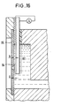
- Fig. 16 is a partial sectional view of the fifth embodiment of the ink jet head of the invention,
- Figs. 17(a), (b) to Figs. 19(a), (b) are drawings showing various alternative shapes of the vibrator used for the fifth embodiment,
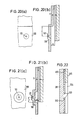
- Figs. 20(a) and (b) are drawings representing a sixth embodiment of the invention, wherein
- (a) shows the shape of a nozzle forming substrate and
- (b) indicates the relation between the nozzle forming substrate and the vibrator,
- Figs. 21(a) and (b) are drawings representing a seventh embodiment of the invention, wherein
- (a) shows the shape of a nozzle forming substrate and
- (b) indicates the relation between the nozzle forming substrate and the vibrator, and
- Fig. 22 is a drawing for explaining a process for manufacturing the nozzle forming substrate of the sixth embodiment.
- Fig. 1 illustrates one embodiment of a recording apparatus having an ink jet head according to the invention mounted thereon. A
recording medium 1 is wound around a platen 4 under the pressure offeed rollers 2 and 3, and is fed in the direction indicated by an arrow 5 during the recording. An ink jet head 9 is mounted on a carriage 8 shiftable in the direction of anarrow 10 parallel to the platen 4 along guide shafts 6, 7. The ink jet head 9 has a plurality of nozzles (not shown in Fig. 1) which can be independently controlled to eject ink droplets. The ink jet head 9 is moved in the direction of anarrow 10 while ink droplets are selectively ejected by its nozzles, and thereby an ink image is formed on therecording medium 1. - Fig. 2 is a perspective view showing the construction of a piezoelectric transducer that can be used in the ink jet head of the present invention. The
transducer 20 comprises a plurality ofvibrators 21, separated bycuts 23 from each other, and afixed portion 22.Signal electrodes 25 consisting of an Au thin layer are formed on one side of respectivepiezoelectric elements 24 consisting of PZT. A metallic plate consisting of an Ni layer is formed as acommon electrode 26 on the other side of thepiezoelectric elements 24. Aspacer 27 consisting of an Ni layer is formed on thefixed portion 22. - Fig. 3(a) is a front view illustrating the shape of a nozzle forming substrate of the present invention. Fig. 3(b) is a sectional view of the nozzle forming portion along line A-A in Fig. 3(a). The
nozzle forming substrate 30 is made of an Ni thin plate having a plurality ofnozzles 31 formed by electroforming. Portions other than a belt-like portion linking neighboring portions ofnozzle inlet openings 34 are removed by etching. A level difference is thus provided forming abed 32 in the neighborhood of thenozzle inlet openings 34 of the nozzle forming substrate. - Fig. 4 is a partial sectional view showing the construction of the ink jet head 9 according to the first embodiment of the present invention. The
nozzle forming substrate 30, thepiezoelectric transducer 20 and anelastic seat 42 are arranged between amain frame 40 and a subframe 41. The subframe 41 has anink reservoir 43 formed therein and ink (not indicated) is fed from theink reservoir 43 to thenozzles 31. The direction into which thepiezoelectric element 24 is polarized is such that the direction of contraction is orthogonal to the electric field established when a voltage is applied between thecommon electrode 26 and thesignal electrode 25. Since the Ni thin layer forming thecommon electrode 26 has a high elastic modulus, when an electric field is applied to the piezoelectric element, a bending moment is generated toward thesignal electrode 25 resulting in a corresponding deformation. Therefore, when a voltage is applied in standby condition and selectively removed, the free end of thevibrator 21 is deformed and displaced towards thenozzle forming substrate 30 to eject ink through thenozzle 31. A gap a between thevibrator 21 and thenozzle 31 is dimensioned so as to obtain a better ink ejection characteristic, and a gap b between thevibrator 21 and the portions of thesubstrate 30 other than thebed 32 of the nozzle inlet openings 34 (Fig. 3(a)) is set so as to operate the vibrator in a proper periodic damping range in order to achieve a smooth feed of ink. - With reference to Fig. 5 the pressure generation mechanism and damping mechanism will now be explained in further detail. As a simple model, when two disks approach each other at a constant velocity as shown in Fig. 5, the pressure built up between the two disks will be given approximately by the following equation:

η: fluid viscosity
V: velocity of one disk relative to the other
P: pressure
h: distance between the disks
2a: diameter of each disk
X and Z are variables as defined in Fig. 5 - A peak pressure is generated near the center of the disk and no pressure is generated at the peripheral edge portion. The value of the pressure depends largely on the distance h between the disks.
- Accordingly, in the case of a beam vibrator as in the first embodiment, it is necessary to control the gap between the nozzle forming substrate in the neighborhood of the nozzles and the vibrator to an appropriate value in order to establish a high pressure at the nozzle portion and obtain an efficient ink ejection. If this gap is excessively small, the resistance of the ink flow to the nozzles increases and the ink will not be fed satisfactorily. Referring to Fig. 4, that means that the dimension a must be controlled to an appropriate value. The gap between the nozzle forming substrate and the vibrator (dimension b in Fig. 4) in the area other than the neighborhood of the nozzles does not influence the pressure generation. If the area where the gap has the dimension a in Fig. 4 is larger than necessary, the ink flow to the nozzles will be affected. Tests have been conducted with various sizes of vibrators and fluids of different viscosities, and the ink ejection characteristic has been evaluated. It was found that the area of the gap with the dimension a should have a width not greater than that of the vibrator. Designating the vibrator width as B (Fig. 2), if the area of the gap keeping the dimension a (this will be referred to as the first area in the following) is expressed by a radius C from the nozzle center, then the relation should be C ≦ B/2. The remaining area of the gap (second area) other than the first area defined by B/2 does not influence the pressure generation at the nozzle portion. Accordingly, from the viewpoint of ejection pressure generation, an efficient ejection may be realized by controlling voids in the neighborhood of the nozzles and also controlling voids in other areas independently from each other. The gap in the second area will be set so as to control the flow resistance and mass load acting on the vibrator by the ink flow caused by a displacement of the vibrator. Thereby, an appropriate periodic damping characteristic of the vibrator can be set. If the gap is larger than an appropriate value, a residual vibration inhibits a high-speed response and further, a plurality of ink drop lets are ejected upon a single driving signal (displacement of the vibrator). If the gap is smaller than the appropriate value, then the flow resistance load will become excessive and a large power will be required for the displacement. It was found experimentally that the flow resistance load in the second area must be decreased if the ink viscosity is more than 5mPas, and thus a < b is preferable. If the ink viscosity is 5mPas or less, it is desirable that an appropriate flow resistance load be provided in the second area, and thus a > b will be preferable.
- The first embodiment concerns the former case, where the ink viscosity is set to 8mPas, the vibrator width to 0,3 mm, gap dimension a to 20 µm, gap dimension b to 40 µm and the dimension C of the bed area to 25 mm.
- Figs. 6(a), (b) to 9(a), (b) are front views illustrating various shapes of the nozzle forming substrate for the ink jet head according to the invention, and sectional views along lines B-B, C-C, D-D, E-E, respectively. The shapes shown in Fig. 6 are intended to enhance the ink feed to the nozzles from all circumferential directions by giving a circular shape to the
bed 32 of a nearby portion to the inlet opening 34 of eachnozzle 31 as compared to the belt-like bed 32 shown in Fig. 3(a). The arrangements shown in Figs. 7 to 9 differ from that shown in Fig. 6 in thatgrooves 33 are provided to extend radially from the nozzle center, thereby further enhancing the ink feed. The bottom of thegrooves 33 is on the same plane as the remaining portions other than thebed 32. In particular, Figs. 7 and 9 are effective in reducing the mutual influence among the nozzles, sincegrooves 33 are not provided in portions of thebed 32 opposing adjacent nozzles. - In the construction explained above, the thickness of the
spacer 27 and the height of thebed 32 will be set appropriately in order to select desired gap dimensions a and b. In order that thevibrators 21 are operated with an appropriate damping, the gap for feeding ink necessary for restoring a nozzle meniscus after ejection of ink droplets is determined by the gap dimension b near to the fixed end of the vibrators. The gap necessary for ejecting ink droplets is determined by the gap dimension a near to the free end of the vibrators. By that an efficient ink jet head having high energy efficiency and satisfying various characteristics such as ejection rate, ejection quantity and ejection recover time at the same time is obtained. - As explained above, in this embodiment a metallic thin plate integrally formed with the piezoelectric element is used as the spacer. However, a separate metallic thin plate may be inserted and fixed between the nozzle forming substrate and the piezoelectric element as the spacer. Further, a cantilever beam type vibrator has been described. However, a similar construction is also realizable with a center beam type vibrator.
- In the embodiment described above, the area of the nozzle inlet opening 34 is wider than that of the outlet opening and thus, the nozzle is horn-like in section. However, the nozzle shape is not particularly limited to this specific shape and it is apparent that other shapes may be employed for the nozzle in the invention.
- Fig. 10 shows another embodiment of the ink jet head using a vibrator form different from that of the previous embodiment. The basic construction is similar to the foregoing embodiment and thus, the following description will concentrate on the differences.
- In Fig. 10, a
vibrator 52 is disposed opposite to eachnozzle 53 through an infinitesimal gap a near to its free end. Awiring 55 is connected to signalelectrodes 54 to selectively apply a voltage to the vibrators. - The construction of the
piezoelectric transducer 56 is shown in Fig. 11. In this embodiment, different from the embodiment shown in Fig. 2, each vibrator has agap controlling layer 57 on a front nose portion. - Fig. 12 shows a partial sectional view of a third embodiment of the ink jet head according to the invention. A
nozzle forming substrate 60 comprises a metallic thin plate having a plurality ofnozzles 61 formed therein and a portion around the nozzle opposite to the free end of avibrator 62 is formed to be thicker than other portions. Avibrator 62 is disposed opposite to eachnozzle 61 through an infinitesimal gap a near to the free end of the vibrator. - In this embodiment, a
groove 64 is formed in a portion of thenozzle forming substrate 60 opposite to the neighborhood of a fixed end of thevibrator 62. Accordingly, the gap b in the neighborhood of the fixed end of the vibrator and the gap a in the neighborhood of the free end of the vibrator are determined by the thickness of a spacer 65 and the depth of thegroove 64. Again, the gap b is determined to obtain a desired periodic damping of thevibrator 62 and the gap a to obtain the necessary ink ejection. - Fig. 13 is a sectional view of the ink jet head according to a fourth embodiment of the invention. A
nozzle forming plate 72, aspacer 73, apiezoelectric transducer 74 and anelastic seat 75 are arranged between amain frame 70 and asubframe 71, fixed together by means ofsetscrews nozzle forming plate 72 comprises a metallic thin plate having a plurality ofnozzles 78 formed therein. Aheater 79 is mounted on the rear side of thesubframe 71 and used to heat the ink jet head up to a working temperature and to dissolve a hot-melt ink (not shown) filled in anink reservoir 80 and around thepiezoelectric transducer 74. The ink has a solid state at room temperature. - Fig. 14 is a perspective view of the
piezoelectric transducer 74. It comprises a plurality ofvibrators 81, separated by cuts and a fixedportion 82. Apiezoelectric element 83 consisting of PZT has asignal electrode 84 consisting of an Au thin layer on one side and acommon electrode 85 consisting of an Ni thin layer on the other side. Thepiezoelectric element 83 and thecommon electrode 85 are joined together by means of a solder (having a fusing point of 140°C) at a temperature of 160°C which is higher than the aforementioned working temperature. Since the coefficient of linear expansion of Ni constituting thecommon electrode 85 is greater than that of thepiezoelectric element 83, a bending moment of a bimetal effect is generated at a working temperature of 110°C, and thus a dished warp with a curvature R⁻¹ is produced on the common electrode side (this condition is shown in Fig. 14). The coefficients of linear expansion of the piezoelectric element and Ni used in this embodiment are 1.8 x 10⁻⁶K⁻¹ and 12.8 x 10⁻⁶K⁻¹, respectively. When the span of the cantilever beam is 3 mm, a dished warp with a curvature R⁻¹ = 6,0 m⁻¹ and a radius of curvature R = 166.7 mm is produced by a temperature difference of 50°C, and a warp y = 27 µm (Fig. 13) is obtained. In Fig. 13, thepiezoelectric transducer 74 is tightly fixed on the nozzle plate so as to keep the tangent of the fixed end of thevibrator 81 in parallel with thenozzle plate 72. The free end of thevibrator 81 is disposed opposite to a correspondingnozzle 78 through an infinitesimal gap near the free end, which is produced by the warp. Thepiezoelectric transducer 74 has its fixed end clamped between themain frame 70 and thesubframe 71 through thespacer 73 and theelastic seat 75. Thepiezoelectric transducer 74 thus remains flat in this area and an internal stress is generated as a consequence. The vibrator is designed with a relatively short fixed end so that the internal stress does not exceed a permissible range, and thereby a damage of the vibrator is prevented. - A
wiring 86 is connected to theindividual signal electrodes 84 in order to selectively energize the vibrators. Thecommon electrodes 85 are independently formed on each vibrator and electrically connected with each other by using Ni for thespacer 73 and an Al or Zn die casting for themain frame 70. - The operation of this embodiment of the invention will be explained next with reference to Fig. 13. A hot-melt ink is fed around the nozzles from the
ink reservoir 80. As with the foregoing embodiment, by applying voltage to the vibrator the nose of the vibrator is displaced and ink ejected from thenozzle 78. - In the above described construction, the gap b for setting an appropriate periodic damping of the
vibrator 81 is determined by the thickness of thespacer 73. A warp y is produced on the free end of thevibrator 81 according to the bimetal effect explained above. Therefore, the gap a between the nozzle and the neighborhood of the free end of the vibrator, necessary for ejecting ink is secured by clamping the fixed end of thevibrator 81 onto thenozzle forming plate 72 through thespacer 73. Thus, when an electrical signal is impressed on the vibrator, it reaches a final displacement under a periodic damping of a long time constant. Therefore, the ink ejection pressure can be maximized and the time for arriving at the maximum ejection pressure can be shortened. Further, even if a member having a different coefficient of linear expansion is provided on the vibrator, since the working temperature is controlled by using a hot-melt ink, a fluctuation of the warp according to the bimetal effect due a change of the environmental temperature can be prevented. - Fig. 15(a) shows a portion of a
vibrator 90 of the piezoelectric transducer of a fifth embodiment of the invention. Fig. 15(a) shows the side of a vibrator portion facing the nozzle forming substrate. Fig. 15(b) is a sectional view taken on line F-F in Fig. 15(a). The piezoelectric transducer of this embodiment comprises a plurality ofvibrators 90 and a fixed portion. Asignal electrode 92 consisting of an Au thin layer is formed on one side of apiezoelectric element 91, and a metallic plate consisting of an Ni layer and serving as acommon electrode 93 is formed on the other side of thepiezoelectric element 91. The metallic plate has on the free end of thevibrator 90 opposite to a nozzle a thickened portion forming acircular projection 94. - Fig. 16 is a partial sectional view illustrating the construction of the ink jet head according to the fifth embodiment of the invention. The gap a between the
projection 94 provided on thevibrator 90 and anozzle forming substrate 95 is sized to enhance the ink droplet ejection characteristic. The gap b between the portion other than theprojection 94 of thevibrator 90, and thenozzle forming substrate 95 is set independently of the gap a such that the vibrator is operated with an appropriate periodic damping and ink is fed smoothly from all circumferential directions to the nozzles. - Fig. 17(a), (b) to Fig. 19(a), (b) are drawings corresponding to Fig. 15(a), (b) and showing alternative constructions of the vibrators. According to Figs. 17 to 19,
grooves 96 are provided in thecircular projection 94 in order to further enhance the ink feed. Thegrooves 96 extend radially from the nozzle center and their bottom is on the same plane as the portions other than theprojection 94. In particular, the alternatives shown in Figs. 17 and 19 are not provided withgrooves 96 on both sides facing to adjacent vibrators, thereby to decrease a mutual influence between the nozzles. - Figs. 20(a) and (b) are a front view and a sectional view, respectively, showing the shape of the nozzle forming substrate of a sixth embodiment of the present invention. This embodiment is suitable for a case where the viscosity of the ink is low, and the relation between the width a of the gap in the first area near to the nozzle and the width b of the gap in the remaining area is set to a > b. Since the basic construction is similar to the foregoing embodiments, no further description will be given here. The
nozzle forming substrate 100 is manufactured by electroforming and hence is constructed generally with a uniform thickness. - As shown in Fig. 22, an electrolyticly plated
layer 203 is formed on a master having aconductor pattern 202 formed on aninsulator 201. Thelayer 203 is coated with a resistlayer 204 and an electrolyticly platedlayer 205 is further formed on portions of thelayer 202 exposed through patterning. Thus, after finally removing the resistlayer 204, a die having a desired nozzle hole and a suitable level difference is obtained by electroforming. An electrolyticly plated layer is formed on the die and thereafter removed from the die to obtain the stepped nozzle forming substrate shown in Fig. 20. When assembled, this nozzle forming substrate results in a gap of width a in a first area and a gap of width b in the remaining second area between the nozzle forming substrate and the vibrator. As to the extension of the first area, reference is made to the description of Figs. 3 to 5. - Figs. 21(a), (b) are a front view and a sectional view, similar to Figs. 20(a), (b), showing the relation between the vibrator and the nozzle forming substrate of a seventh embodiment. In Figs. 21(a), (b) the same reference numerals as in Figs. 20(a), (b) are used. Like the sixth embodiment, the seventh embodiment is intended for the case where the viscosity of the ink is low. In a circular shaped first area of radius c in the neighborhood of the nozzle, the nozzle forming substrate has a recess resulting in a gap width a which is larger than the gap width b in the remaining area of the gap between the nozzle forming substrate and the vibrator.
- As described above, the gap between the nozzle forming substrate and the vibrator is divided into a first area near to a nozzle inlet opening of the nozzle forming substrate and a remaining second area. The gap width in the first area is different from that in the second area. The width a of the gap in the first area has a value necessary for the ink ejection. The gap width b in the second area providing a feed passage for the ink is selected so as to allow a quick restoration of a nozzle meniscus after ejection of an ink droplet. Thus, the time for the ink to be refilled is controlled to a proper value. Thereby, the recover time can be shortened while keeping the ink droplet ejection rate and the ejection quantity at desired values. Thus, the present invention provides an ink jet head superior in performance by improving various characteristics such as ink droplet ejection rate, ejection quantity, ejection recover time and ejection stability and the like at the same time.
- Further, since the gap width between the vibrator and the nozzle forming substrate in the said second area can be set to a value allowing the vibrator to operate in an appropriate periodic damping range, the energy consumption due to the viscosity of the ink existing in the gap between the vibrator and the nozzle forming substrate will be decreased allowing an operation at a relatively low driving voltage. Since the gap width of the first area and the second area can be set independently, a margin for setting each width will be expanded, thereby enhancing the production yield.
Claims (3)
characterized in that
the width (a) of the gap in a first area near to and around said nozzles (31) is different from the width (b) of the gap in a remaining second area.
Applications Claiming Priority (6)
| Application Number | Priority Date | Filing Date | Title |
|---|---|---|---|
| JP89372/88 | 1988-04-12 | ||
| JP8937288A JPH01259955A (en) | 1988-04-12 | 1988-04-12 | Ink jet head |
| JP137888/88 | 1988-06-03 | ||
| JP13788888A JPH01306256A (en) | 1988-06-03 | 1988-06-03 | Ink jet head |
| JP155891/88 | 1988-06-23 | ||
| JP15589188A JPH024517A (en) | 1988-06-23 | 1988-06-23 | Ink jet head |
Publications (3)
| Publication Number | Publication Date |
|---|---|
| EP0337429A2 true EP0337429A2 (en) | 1989-10-18 |
| EP0337429A3 EP0337429A3 (en) | 1990-08-22 |
| EP0337429B1 EP0337429B1 (en) | 1993-07-07 |
Family
ID=27306098
Family Applications (1)
| Application Number | Title | Priority Date | Filing Date |
|---|---|---|---|
| EP89106516A Expired - Lifetime EP0337429B1 (en) | 1988-04-12 | 1989-04-12 | Ink jet head |
Country Status (4)
| Country | Link |
|---|---|
| US (1) | US4962391A (en) |
| EP (1) | EP0337429B1 (en) |
| DE (1) | DE68907434T2 (en) |
| HK (1) | HK71995A (en) |
Cited By (12)
| Publication number | Priority date | Publication date | Assignee | Title |
|---|---|---|---|---|
| EP0372521A2 (en) * | 1988-12-07 | 1990-06-13 | Seiko Epson Corporation | On-demand type ink jet print head |
| EP0427291A1 (en) * | 1989-11-10 | 1991-05-15 | Seiko Epson Corporation | Ink jet print head |
| WO1998000237A1 (en) * | 1996-07-01 | 1998-01-08 | Joachim Heinzl | Droplet mist generator |
| EP0865922A2 (en) * | 1997-02-25 | 1998-09-23 | Hewlett-Packard Company | Reduced spray inkjet printhead orifice |
| EP0993951A2 (en) * | 1998-10-12 | 2000-04-19 | Matsushita Electric Industrial Co., Ltd. | Liquid ejection device, manufacturing method therefor, liquid ejection method and manufacturing method for piezo-electric actuator |
| CN1056802C (en) * | 1989-09-18 | 2000-09-27 | 佳能公司 | Ink jet recording head and ink jet recording apparatus using same |
| WO2001017782A1 (en) * | 1999-09-09 | 2001-03-15 | Hewlett-Packard Company | Counter-boring techniques for ink-jet printheads |
| US6371596B1 (en) | 1995-10-25 | 2002-04-16 | Hewlett-Packard Company | Asymmetric ink emitting orifices for improved inkjet drop formation |
| EP1285762A3 (en) * | 2001-08-10 | 2003-04-02 | Tally Computerdrucker GmbH | Microdroplets generator in particular for ink jet printers |
| US6938988B2 (en) | 2003-02-10 | 2005-09-06 | Hewlett-Packard Development Company, L.P. | Counter-bore of a fluid ejection device |
| EP2147791A1 (en) * | 2008-07-22 | 2010-01-27 | Océ-Technologies B.V. | Method of manufacturing a droplet jetting device and an ink jet device |
| WO2013182393A1 (en) * | 2012-06-08 | 2013-12-12 | Oce-Technologies B.V. | Droplet ejection device |
Families Citing this family (41)
| Publication number | Priority date | Publication date | Assignee | Title |
|---|---|---|---|---|
| JPH0764060B2 (en) * | 1989-06-09 | 1995-07-12 | シャープ株式会社 | Inkjet printer |
| JP2841750B2 (en) * | 1989-07-03 | 1998-12-24 | セイコーエプソン株式会社 | On-demand type inkjet print head |
| US5255016A (en) * | 1989-09-05 | 1993-10-19 | Seiko Epson Corporation | Ink jet printer recording head |
| US5189443A (en) * | 1989-09-18 | 1993-02-23 | Canon Kabushiki Kaisha | Recording head having stress-minimizing construction |
| US5703632A (en) * | 1989-09-18 | 1997-12-30 | Canon Kabushiki Kaisha | Ink jet head orifice plate mounting arrangement |
| JP3041952B2 (en) * | 1990-02-23 | 2000-05-15 | セイコーエプソン株式会社 | Ink jet recording head, piezoelectric vibrator, and method of manufacturing these |
| US6186619B1 (en) | 1990-02-23 | 2001-02-13 | Seiko Epson Corporation | Drop-on-demand ink-jet printing head |
| JP2728980B2 (en) * | 1991-01-07 | 1998-03-18 | シャープ株式会社 | Inkjet head device |
| JPH05177834A (en) * | 1991-06-04 | 1993-07-20 | Seiko Epson Corp | Ink jet recording head |
| US5450107A (en) * | 1991-12-27 | 1995-09-12 | Xerox Corporation | Surface ripple wave suppression by anti-reflection in apertured free ink surface level controllers for acoustic ink printers |
| US5592202A (en) * | 1994-11-10 | 1997-01-07 | Laser Master Corporation | Ink jet print head rail assembly |
| KR0185329B1 (en) * | 1996-03-27 | 1999-05-15 | 이형도 | Recording method using motor inertia of recording liquid |
| US5901425A (en) | 1996-08-27 | 1999-05-11 | Topaz Technologies Inc. | Inkjet print head apparatus |
| US6002549A (en) * | 1996-11-01 | 1999-12-14 | Seagate Technology, Inc. | Dither microactors for stiction release in magnetic disc drives |
| WO1998020486A1 (en) | 1996-11-01 | 1998-05-14 | Seagate Technology, Inc. | Actuator arm integrated piezoelectric microactuator |
| US6396667B1 (en) | 1997-06-24 | 2002-05-28 | Seagate Technology Llc | Electromagnetic disc drive microactuator and suspension |
| US6712453B2 (en) | 1997-07-15 | 2004-03-30 | Silverbrook Research Pty Ltd. | Ink jet nozzle rim |
| US7465030B2 (en) | 1997-07-15 | 2008-12-16 | Silverbrook Research Pty Ltd | Nozzle arrangement with a magnetic field generator |
| US7556356B1 (en) * | 1997-07-15 | 2009-07-07 | Silverbrook Research Pty Ltd | Inkjet printhead integrated circuit with ink spread prevention |
| US6648453B2 (en) | 1997-07-15 | 2003-11-18 | Silverbrook Research Pty Ltd | Ink jet printhead chip with predetermined micro-electromechanical systems height |
| US7468139B2 (en) | 1997-07-15 | 2008-12-23 | Silverbrook Research Pty Ltd | Method of depositing heater material over a photoresist scaffold |
| US6188415B1 (en) | 1997-07-15 | 2001-02-13 | Silverbrook Research Pty Ltd | Ink jet printer having a thermal actuator comprising an external coil spring |
| US7337532B2 (en) * | 1997-07-15 | 2008-03-04 | Silverbrook Research Pty Ltd | Method of manufacturing micro-electromechanical device having motion-transmitting structure |
| US7195339B2 (en) | 1997-07-15 | 2007-03-27 | Silverbrook Research Pty Ltd | Ink jet nozzle assembly with a thermal bend actuator |
| US6682174B2 (en) | 1998-03-25 | 2004-01-27 | Silverbrook Research Pty Ltd | Ink jet nozzle arrangement configuration |
| US7246884B2 (en) * | 1997-07-15 | 2007-07-24 | Silverbrook Research Pty Ltd | Inkjet printhead having enclosed inkjet actuators |
| US6935724B2 (en) | 1997-07-15 | 2005-08-30 | Silverbrook Research Pty Ltd | Ink jet nozzle having actuator with anchor positioned between nozzle chamber and actuator connection point |
| US6269687B1 (en) | 1997-09-22 | 2001-08-07 | Seagate Technology Llc | Force sensing slider |
| US6067215A (en) * | 1997-10-09 | 2000-05-23 | Seagate Technology, Inc. | Magnetic shielding for electromagnetic microactuator |
| US6163434A (en) * | 1997-10-23 | 2000-12-19 | Seagate Technology Llc | Piezoresistive position sensors embedded in disc drive microactuator |
| US6078473A (en) * | 1998-05-13 | 2000-06-20 | Seagate Technology, Inc. | Gimbal flexure for use with microactuator |
| AU2000242753B2 (en) * | 2000-04-18 | 2004-09-30 | Zamtec Limited | Ink jet ejector |
| US20060000925A1 (en) * | 2004-06-30 | 2006-01-05 | Maher Colin G | Reduced sized micro-fluid jet nozzle structure |
| JP2008055643A (en) * | 2006-08-29 | 2008-03-13 | Canon Inc | Recording head |
| DE102010028435A1 (en) | 2009-05-19 | 2010-11-25 | Ebs Ink-Jet Systeme Gmbh | Printing head for ink jet printer and method of nozzle cleaning, employ spring-returned, solenoid-operated nozzle valve with valve plug internal to ink tank |
| US8628180B2 (en) * | 2010-10-26 | 2014-01-14 | Eastman Kodak Company | Liquid dispenser including vertical outlet opening wall |
| CA3099749A1 (en) | 2018-05-11 | 2019-11-14 | Matthews International Corporation | Electrode structures for micro-valves for use in jetting assemblies |
| US11794476B2 (en) | 2018-05-11 | 2023-10-24 | Matthews International Corporation | Micro-valves for use in jetting assemblies |
| WO2019215672A1 (en) | 2018-05-11 | 2019-11-14 | Matthews International Corporation | Systems and methods for controlling operation of micro-valves for use in jetting assemblies |
| MX2020012074A (en) | 2018-05-11 | 2021-03-09 | Matthews Int Corp | Systems and methods for sealing micro-valves for use in jetting assemblies. |
| US11639057B2 (en) | 2018-05-11 | 2023-05-02 | Matthews International Corporation | Methods of fabricating micro-valves and jetting assemblies including such micro-valves |
Citations (4)
| Publication number | Priority date | Publication date | Assignee | Title |
|---|---|---|---|---|
| US4072959A (en) * | 1975-06-20 | 1978-02-07 | Siemens Aktiengesellschaft | Recorder operating with drops of liquid |
| DE3028404A1 (en) * | 1980-07-26 | 1982-07-22 | NCR Corp., 45479 Dayton, Ohio | Ink jet printer with strip type nozzle - having arrays of piezoelectric drive stages avoiding cross-talk |
| US4564851A (en) * | 1983-02-22 | 1986-01-14 | Siemens Aktiengesellschaft | Recording device functioning with fluid droplets |
| JPS62179948A (en) * | 1986-02-03 | 1987-08-07 | Ricoh Co Ltd | Vibration unit in ink jet recording apparatus |
Family Cites Families (6)
| Publication number | Priority date | Publication date | Assignee | Title |
|---|---|---|---|---|
| DE2728657A1 (en) * | 1977-06-24 | 1979-01-04 | Siemens Ag | NOZZLE PLATE FOR INK WRITING DEVICES |
| DE3114259A1 (en) * | 1981-04-08 | 1982-11-04 | Siemens AG, 1000 Berlin und 8000 München | WRITING DEVICE WORKING WITH LIQUID DROPS |
| DE3114192A1 (en) * | 1981-04-08 | 1982-10-28 | Siemens AG, 1000 Berlin und 8000 München | WRITING DEVICE WORKING WITH LIQUID DROPS |
| DE3114224A1 (en) * | 1981-04-08 | 1982-11-04 | Siemens AG, 1000 Berlin und 8000 München | WRITING DEVICE WORKING WITH LIQUID DROPS |
| DE3320441A1 (en) * | 1983-06-06 | 1984-12-06 | Siemens AG, 1000 Berlin und 8000 München | WRITING DEVICE WORKING WITH LIQUID DROPLETS WITH ROD-SHAPED PIEZOELECTRIC TRANSFORMERS CONNECTED ON BOTH ENDS WITH A NOZZLE PLATE |
| JPS644964A (en) * | 1987-06-26 | 1989-01-10 | Hitachi Ltd | Magnetic head supporting device |
-
1989
- 1989-04-12 US US07/336,964 patent/US4962391A/en not_active Expired - Lifetime
- 1989-04-12 DE DE89106516T patent/DE68907434T2/en not_active Expired - Fee Related
- 1989-04-12 EP EP89106516A patent/EP0337429B1/en not_active Expired - Lifetime
-
1995
- 1995-05-11 HK HK71995A patent/HK71995A/en not_active IP Right Cessation
Patent Citations (4)
| Publication number | Priority date | Publication date | Assignee | Title |
|---|---|---|---|---|
| US4072959A (en) * | 1975-06-20 | 1978-02-07 | Siemens Aktiengesellschaft | Recorder operating with drops of liquid |
| DE3028404A1 (en) * | 1980-07-26 | 1982-07-22 | NCR Corp., 45479 Dayton, Ohio | Ink jet printer with strip type nozzle - having arrays of piezoelectric drive stages avoiding cross-talk |
| US4564851A (en) * | 1983-02-22 | 1986-01-14 | Siemens Aktiengesellschaft | Recording device functioning with fluid droplets |
| JPS62179948A (en) * | 1986-02-03 | 1987-08-07 | Ricoh Co Ltd | Vibration unit in ink jet recording apparatus |
Non-Patent Citations (1)
| Title |
|---|
| PATENT ABSTRACTS OF JAPAN, vol. 12, no. 21 (M-661)(2868) 22 January 1988; & JP-A-62 179 948 (RICOH CO. LTD.) 07-08-1987 * |
Cited By (22)
| Publication number | Priority date | Publication date | Assignee | Title |
|---|---|---|---|---|
| EP0372521A2 (en) * | 1988-12-07 | 1990-06-13 | Seiko Epson Corporation | On-demand type ink jet print head |
| EP0372521A3 (en) * | 1988-12-07 | 1990-12-05 | Seiko Epson Corporation | On-demand type ink jet print head |
| US5072240A (en) * | 1988-12-07 | 1991-12-10 | Seiko Epson Corporation | On-demand type ink jet print head |
| CN1056802C (en) * | 1989-09-18 | 2000-09-27 | 佳能公司 | Ink jet recording head and ink jet recording apparatus using same |
| EP0427291A1 (en) * | 1989-11-10 | 1991-05-15 | Seiko Epson Corporation | Ink jet print head |
| US5184155A (en) * | 1989-11-10 | 1993-02-02 | Seiko Epson Corporation | Ink jet print head |
| US6371596B1 (en) | 1995-10-25 | 2002-04-16 | Hewlett-Packard Company | Asymmetric ink emitting orifices for improved inkjet drop formation |
| US6123413A (en) * | 1995-10-25 | 2000-09-26 | Hewlett-Packard Company | Reduced spray inkjet printhead orifice |
| US6116517A (en) * | 1996-07-01 | 2000-09-12 | Joachim Heinzl | Droplet mist generator |
| WO1998000237A1 (en) * | 1996-07-01 | 1998-01-08 | Joachim Heinzl | Droplet mist generator |
| EP0865922A2 (en) * | 1997-02-25 | 1998-09-23 | Hewlett-Packard Company | Reduced spray inkjet printhead orifice |
| EP0865922A3 (en) * | 1997-02-25 | 1999-06-16 | Hewlett-Packard Company | Reduced spray inkjet printhead orifice |
| US6497476B1 (en) | 1998-10-12 | 2002-12-24 | Matsushita Electric Industrial Co., Ltd. | Liquid injection device, manufacturing method therefor, liquid injection method and manufacturing method for piezo-electric actuator |
| EP0993951A2 (en) * | 1998-10-12 | 2000-04-19 | Matsushita Electric Industrial Co., Ltd. | Liquid ejection device, manufacturing method therefor, liquid ejection method and manufacturing method for piezo-electric actuator |
| EP0993951A3 (en) * | 1998-10-12 | 2000-08-02 | Matsushita Electric Industrial Co., Ltd. | Liquid ejection device, manufacturing method therefor, liquid ejection method and manufacturing method for piezo-electric actuator |
| WO2001017782A1 (en) * | 1999-09-09 | 2001-03-15 | Hewlett-Packard Company | Counter-boring techniques for ink-jet printheads |
| US6527370B1 (en) | 1999-09-09 | 2003-03-04 | Hewlett-Packard Company | Counter-boring techniques for improved ink-jet printheads |
| EP1285762A3 (en) * | 2001-08-10 | 2003-04-02 | Tally Computerdrucker GmbH | Microdroplets generator in particular for ink jet printers |
| US6938988B2 (en) | 2003-02-10 | 2005-09-06 | Hewlett-Packard Development Company, L.P. | Counter-bore of a fluid ejection device |
| EP2147791A1 (en) * | 2008-07-22 | 2010-01-27 | Océ-Technologies B.V. | Method of manufacturing a droplet jetting device and an ink jet device |
| WO2013182393A1 (en) * | 2012-06-08 | 2013-12-12 | Oce-Technologies B.V. | Droplet ejection device |
| US9216577B2 (en) | 2012-06-08 | 2015-12-22 | Oce-Technologies B.V. | Droplet ejection device |
Also Published As
| Publication number | Publication date |
|---|---|
| EP0337429B1 (en) | 1993-07-07 |
| DE68907434D1 (en) | 1993-08-12 |
| DE68907434T2 (en) | 1994-03-03 |
| US4962391A (en) | 1990-10-09 |
| HK71995A (en) | 1995-05-19 |
| EP0337429A3 (en) | 1990-08-22 |
Similar Documents
| Publication | Publication Date | Title |
|---|---|---|
| EP0337429A2 (en) | Ink jet head | |
| EP0485241B1 (en) | Ink jet head | |
| EP0573055B1 (en) | Ink jet recording head | |
| US5278585A (en) | Ink jet printhead with ink flow directing valves | |
| US5252994A (en) | Ink-jet recording head | |
| US6695437B2 (en) | Inkjet recording head and method for driving an inkjet recording head | |
| EP0277703A1 (en) | Droplet deposition apparatus | |
| EP0528649B1 (en) | Method of manufacturing a high density ink jet printhead array | |
| JP3328609B2 (en) | Ink jet printer head actuator and method of manufacturing the same | |
| EP0795404B1 (en) | Ink jet recording head | |
| EP0897801B1 (en) | Ink-jet recording head | |
| US5373314A (en) | Ink jet print head | |
| EP0855275B1 (en) | Ink-jet recording head | |
| US7159793B2 (en) | Liquid discharging head and liquid discharging device | |
| DE60120179T2 (en) | Piezoelectric vibrator unit | |
| US5543009A (en) | Method of manufacturing a sidewall actuator array for an ink jet printhead | |
| JP2881616B2 (en) | Ink jet head device | |
| US5898448A (en) | Ink ejecting device having ink chambers of differing shapes | |
| JP3125536B2 (en) | Inkjet head | |
| US6435671B1 (en) | Actuator for inkjet print head | |
| KR100327252B1 (en) | Inkjet printhead actuator and manufacturing method thereof | |
| JP2001010065A (en) | Ink-jet recording head, ink-jet recording apparatus, production of nozzle plate, and production of ink-jet recording head | |
| JPH01306256A (en) | Ink jet head | |
| JPH024517A (en) | Ink jet head | |
| JPH02301444A (en) | Ink jet head |
Legal Events
| Date | Code | Title | Description |
|---|---|---|---|
| PUAI | Public reference made under article 153(3) epc to a published international application that has entered the european phase |
Free format text: ORIGINAL CODE: 0009012 |
|
| AK | Designated contracting states |
Kind code of ref document: A2 Designated state(s): DE FR GB |
|
| PUAL | Search report despatched |
Free format text: ORIGINAL CODE: 0009013 |
|
| AK | Designated contracting states |
Kind code of ref document: A3 Designated state(s): DE FR GB |
|
| 17P | Request for examination filed |
Effective date: 19900814 |
|
| 17Q | First examination report despatched |
Effective date: 19920317 |
|
| GRAA | (expected) grant |
Free format text: ORIGINAL CODE: 0009210 |
|
| AK | Designated contracting states |
Kind code of ref document: B1 Designated state(s): DE FR GB |
|
| REF | Corresponds to: |
Ref document number: 68907434 Country of ref document: DE Date of ref document: 19930812 |
|
| ET | Fr: translation filed | ||
| PLBE | No opposition filed within time limit |
Free format text: ORIGINAL CODE: 0009261 |
|
| STAA | Information on the status of an ep patent application or granted ep patent |
Free format text: STATUS: NO OPPOSITION FILED WITHIN TIME LIMIT |
|
| 26N | No opposition filed | ||
| REG | Reference to a national code |
Ref country code: GB Ref legal event code: IF02 |
|
| PGFP | Annual fee paid to national office [announced via postgrant information from national office to epo] |
Ref country code: DE Payment date: 20060406 Year of fee payment: 18 |
|
| PGFP | Annual fee paid to national office [announced via postgrant information from national office to epo] |
Ref country code: FR Payment date: 20060410 Year of fee payment: 18 |
|
| PGFP | Annual fee paid to national office [announced via postgrant information from national office to epo] |
Ref country code: GB Payment date: 20060412 Year of fee payment: 18 |
|
| GBPC | Gb: european patent ceased through non-payment of renewal fee |
Effective date: 20070412 |
|
| PG25 | Lapsed in a contracting state [announced via postgrant information from national office to epo] |
Ref country code: DE Free format text: LAPSE BECAUSE OF NON-PAYMENT OF DUE FEES Effective date: 20071101 |
|
| PG25 | Lapsed in a contracting state [announced via postgrant information from national office to epo] |
Ref country code: GB Free format text: LAPSE BECAUSE OF NON-PAYMENT OF DUE FEES Effective date: 20070412 |
|
| PG25 | Lapsed in a contracting state [announced via postgrant information from national office to epo] |
Ref country code: FR Free format text: LAPSE BECAUSE OF NON-PAYMENT OF DUE FEES Effective date: 20070430 |