EP0338400A2 - Capacitive sensor for determining the liquid level in a container - Google Patents
Capacitive sensor for determining the liquid level in a container Download PDFInfo
- Publication number
- EP0338400A2 EP0338400A2 EP89106489A EP89106489A EP0338400A2 EP 0338400 A2 EP0338400 A2 EP 0338400A2 EP 89106489 A EP89106489 A EP 89106489A EP 89106489 A EP89106489 A EP 89106489A EP 0338400 A2 EP0338400 A2 EP 0338400A2
- Authority
- EP
- European Patent Office
- Prior art keywords
- electrodes
- level
- impedance
- sensor according
- liquid
- Prior art date
- Legal status (The legal status is an assumption and is not a legal conclusion. Google has not performed a legal analysis and makes no representation as to the accuracy of the status listed.)
- Granted
Links
Images

Classifications
-
- B—PERFORMING OPERATIONS; TRANSPORTING
- B60—VEHICLES IN GENERAL
- B60T—VEHICLE BRAKE CONTROL SYSTEMS OR PARTS THEREOF; BRAKE CONTROL SYSTEMS OR PARTS THEREOF, IN GENERAL; ARRANGEMENT OF BRAKING ELEMENTS ON VEHICLES IN GENERAL; PORTABLE DEVICES FOR PREVENTING UNWANTED MOVEMENT OF VEHICLES; VEHICLE MODIFICATIONS TO FACILITATE COOLING OF BRAKES
- B60T17/00—Component parts, details, or accessories of power brake systems not covered by groups B60T8/00, B60T13/00 or B60T15/00, or presenting other characteristic features
- B60T17/18—Safety devices; Monitoring
- B60T17/22—Devices for monitoring or checking brake systems; Signal devices
- B60T17/225—Devices for monitoring or checking brake systems; Signal devices brake fluid level indicators
-
- G—PHYSICS
- G01—MEASURING; TESTING
- G01F—MEASURING VOLUME, VOLUME FLOW, MASS FLOW OR LIQUID LEVEL; METERING BY VOLUME
- G01F23/00—Indicating or measuring liquid level or level of fluent solid material, e.g. indicating in terms of volume or indicating by means of an alarm
- G01F23/22—Indicating or measuring liquid level or level of fluent solid material, e.g. indicating in terms of volume or indicating by means of an alarm by measuring physical variables, other than linear dimensions, pressure or weight, dependent on the level to be measured, e.g. by difference of heat transfer of steam or water
- G01F23/24—Indicating or measuring liquid level or level of fluent solid material, e.g. indicating in terms of volume or indicating by means of an alarm by measuring physical variables, other than linear dimensions, pressure or weight, dependent on the level to be measured, e.g. by difference of heat transfer of steam or water by measuring variations of resistance of resistors due to contact with conductor fluid
-
- G—PHYSICS
- G01—MEASURING; TESTING
- G01F—MEASURING VOLUME, VOLUME FLOW, MASS FLOW OR LIQUID LEVEL; METERING BY VOLUME
- G01F23/00—Indicating or measuring liquid level or level of fluent solid material, e.g. indicating in terms of volume or indicating by means of an alarm
- G01F23/22—Indicating or measuring liquid level or level of fluent solid material, e.g. indicating in terms of volume or indicating by means of an alarm by measuring physical variables, other than linear dimensions, pressure or weight, dependent on the level to be measured, e.g. by difference of heat transfer of steam or water
- G01F23/26—Indicating or measuring liquid level or level of fluent solid material, e.g. indicating in terms of volume or indicating by means of an alarm by measuring physical variables, other than linear dimensions, pressure or weight, dependent on the level to be measured, e.g. by difference of heat transfer of steam or water by measuring variations of capacity or inductance of capacitors or inductors arising from the presence of liquid or fluent solid material in the electric or electromagnetic fields
- G01F23/263—Indicating or measuring liquid level or level of fluent solid material, e.g. indicating in terms of volume or indicating by means of an alarm by measuring physical variables, other than linear dimensions, pressure or weight, dependent on the level to be measured, e.g. by difference of heat transfer of steam or water by measuring variations of capacity or inductance of capacitors or inductors arising from the presence of liquid or fluent solid material in the electric or electromagnetic fields by measuring variations in capacitance of capacitors
- G01F23/266—Indicating or measuring liquid level or level of fluent solid material, e.g. indicating in terms of volume or indicating by means of an alarm by measuring physical variables, other than linear dimensions, pressure or weight, dependent on the level to be measured, e.g. by difference of heat transfer of steam or water by measuring variations of capacity or inductance of capacitors or inductors arising from the presence of liquid or fluent solid material in the electric or electromagnetic fields by measuring variations in capacitance of capacitors measuring circuits therefor
-
- G—PHYSICS
- G01—MEASURING; TESTING
- G01N—INVESTIGATING OR ANALYSING MATERIALS BY DETERMINING THEIR CHEMICAL OR PHYSICAL PROPERTIES
- G01N27/00—Investigating or analysing materials by the use of electric, electrochemical, or magnetic means
- G01N27/02—Investigating or analysing materials by the use of electric, electrochemical, or magnetic means by investigating impedance
- G01N27/22—Investigating or analysing materials by the use of electric, electrochemical, or magnetic means by investigating impedance by investigating capacitance
- G01N27/221—Investigating or analysing materials by the use of electric, electrochemical, or magnetic means by investigating impedance by investigating capacitance by investigating the dielectric properties
Definitions
- the invention relates to a sensor with the features specified in the preamble of claim 1.
- a sensor is known from DE-OS 23 19 008. It is a capacitive level switch for checking the brake fluid level in the hydraulic brake system of motor vehicles, which emits a warning signal when the level falls below a predetermined level.
- the level at which this warning signal is emitted can be varied by arranging the sensor in the brake fluid reservoir to be adjustable in height. With the known sensor, however, the current level of the brake fluid cannot be observed and displayed.
- Reservoir for the brake fluid in the hydraulic brake systems of motor vehicles usually have a ventilation opening.
- the brake fluid absorbs air moisture through this ventilation opening and gradually becomes enriched with water. Too much water in the brake fluid can lead to life-threatening failure of the brake system. It would therefore be useful to know the water content of the brake fluid.
- a sensor for continuously monitoring the water content of brake fluid is not yet known.
- DE-OS 34 13 135 it is known from DE-OS 34 13 135 to determine the water content of liquids, e.g. of lubricating oil to be determined by means of a special capacitive sensor in which a non-conductive membrane is arranged between two electrodes, into which the liquid to be examined can penetrate. For the determination of the water content, the dielectric behavior of the liquid, which changes with the water content, is observed.
- this known sensor is not used for filling level monitoring.
- the invention has for its object to provide the simplest possible, suitable for mass production, for the continuous monitoring of the level and the water content of brake fluid in motor vehicles.
- both the fill level (level) of the brake fluid and its water content can be determined, and this is done by measuring and evaluating the complex impedance of the sensor at at least two different frequencies realize that in the brake fluid immersing electrodes of the connected circuit present a complete impedance, which is represented as a series connection of an ohmic active resistor and one or two capacitive reactances.
- the ohmic resistance is given by the resistance of the brake fluid between the electrodes.
- the capacitive reactance is determined by the capacitance of the capacitor, which is formed by the electrode coated with an electrically insulating material, the brake fluid as the counter electrode and the electrically insulating cover layer as the dielectric. If - as is preferred - both electrodes carry such a cover layer made of electrically insulating material, the capacitive reactance is determined by the capacitance of the series connection of two such capacitors with the brake fluid as a common counter electrode.
- the capacitive reactance of the sensor is measured, best with the help of an alternating current, the frequency of which is chosen so low that at this frequency the capacitive reactance of the impedance of the sensor is large against the ohmic effective resistance. Since the dimensions and the arrangement of the electrodes as well as the dielectric which also determines the capacitive reactance (the non-conductive cover layer on the electrode or electrodes) are known and constant, the capacitive reactance only from the effective electrode area, that is the immersed electrode area, i.e. from the immersion depth of the electrodes. The measured capacitive reactance is therefore a direct measure of the level of the brake fluid in the reservoir.
- the ohmic effective resistance of the sensor is determined, and best with the help of an alternating current, the frequency f2 of which is chosen so high that the ohmic resistance measured at this frequency is large against the capacitive resistance.
- This ohmic resistance is the ohmic resistance of the brake fluid between the two electrodes and is determined by the dimensions and arrangement of the electrodes, the immersion depth of the electrodes in the brake fluid and the specific resistance of the brake fluid. The dimensions and arrangement of the two electrodes are known and constant, the immersion depth of the electrodes in the brake fluid is variable, but is known from the previous level measurement.
- the quotient of the measured effective resistance and the previously determined immersion depth of the electrodes is therefore a direct measure of the specific resistance of the brake fluid, for its part depends in a characteristic manner on the water content of the brake fluid.
- the evaluation circuit can therefore determine the water content from the determined specific resistance, preferably by means of a microcomputer, which compares the determined specific resistance with a characteristic curve which is predetermined and stored in it and which indicates the dependence of the specific resistance on the water content.
- the structure and type of the electrodes used there are no special requirements for the structure and type of the electrodes used, with the exception of the requirement that at least one of the electrodes should have a cover layer made of electrically insulating material, which insulates the electrically conductive core of the electrode from the liquid, this cover layer being as possible should be tight so that the liquid to be monitored does not penetrate it and change its dielectric property.
- An arrangement comprising a rod-shaped electrode and a tubular electrode surrounding it coaxially is particularly suitable, since such an arrangement is particularly compact and easy to handle, and fluctuations in the liquid level as a result of driving movements are dampened in such an electrode arrangement.
- the associated circuit can be a highly integrated, compact and inexpensive electronic circuit.
- a digital sine generator is preferably used, as described, for example, in DE-Z Elektronik, number 17, 1983, pages 52 and 52 or in the older, but not previously published DE-A-36 43 389 is described.
- a digitally operating measuring device which is disclosed in the older, but not prepublished EP-A-0 271 849, is particularly suitable for the impedance measurement.
- This measuring device has a microcomputer for evaluating the measured values, which can advantageously also be used to derive level signals and water content signals from the measured values and to display them.
- the construction of the sensor according to the invention is thus very compact and inexpensive to manufacture. It can be used without difficulty instead of a level switch that was previously used to monitor the level of brake fluid and not only provides a signal when the level falls below a specified level, but can also fill the level over a larger level range - depending on the maximum immersion depth of the electrodes - and also the current level Display the water content of the brake fluid.
- the possible applications of the sensor according to the invention are not limited to the monitoring of brake fluid, it can rather be used wherever it is a question of at least weakly conductive intermiscible liquids with regard to their mixing ratio or a liquid which changes in its specific resistance with regard to its condition and Monitor fill level.
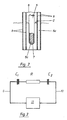
- FIG. 1 shows a reservoir 1 which is filled to a level 2 with a brake fluid.
- the reservoir 1 has on its top a filler neck 3, which is closed by a lid 4.
- the cover 4 consists of an electrically insulating plastic and has two electrodes 5 and 6 on its underside.
- the electrode 5 is a rod-shaped inner electrode and the electrode 6 is a tubular outer electrode coaxially surrounding the inner electrode 5.
- Both electrodes are made of titanium and have a cover layer 7 or 8 made of titanium dioxide, which can be formed by allowing the titanium to oxidize in air.
- the cover layers 7 and 8 are conductive and so dense that they do not contain any brake fluid let in. Only the non-oxidized core 5a or 6a of the electrodes is electrically conductive.
- the electrodes are both immersed in the brake fluid.
- the electrodes 5 and 6 are each connected to an electrical line 9 and 10, which are passed through the cover 4 and lead to an electronic circuit 11.
- the inner electrode 5 has a diameter of 4 mm
- the outer electrode 6 has an inner diameter of 10 mm
- both electrodes are 40 mm long and their cover layer 7 or 8 made of titanium is a few ⁇ m thick. This enables immersion depths between 10 mm and 25 mm and water content in brake fluid of less than 0.05% to be determined.
- FIG. 3 shows the equivalent circuit diagram of this arrangement. It consists of this circuit 11 and two capacitors C1 and C2 and an ohmic resistor R in series connection.
- the circuit 11 serves to determine the complex impedance
- the capacitance C1 is the capacitance of the capacitor, which is formed by the core 5a of the inner electrode as the first electrode, the brake fluid in the electrode arrangement up to level 2 as the counter electrode and the cover layer 7 as the dielectric.
- the capacitance C2 is the capacitance of the capacitor, which is formed by the core 6a of the outer electrode as the first electrode, by the brake fluid up to level 2 as the counter electrode and by the cover layer 8 as the dielectric.
- R is the ohmic resistance of the brake fluid in the outer electrode.
- the capacitance C1 + C2 depends solely on the effective electrode area, that is the surface of the electrodes 5 and 6 wetted by the brake fluid, that is to say only on the immersion depth of the electrodes 5 and 6 in the brake fluid.
- the ohmic resistance R depends on the immersion depth of the electrodes in the brake fluid and on their current specific resistance.
- C1 + C2 is determined by supplying the electrode arrangement with an alternating current, the frequency of which is so low that the capacitive reactance is large against the ohmic effective resistance R.
- the reactance is a direct measure of the immersion depth of the electrodes in the brake fluid and thus for the level 2 to be determined.
- the active resistance R is determined by feeding the electrode arrangement with an alternating current, the frequency f 2 of which is so large that the active resistance R is large is against the capacitive reactance.
- the effective resistance R is smaller, the greater the immersion depth of the electrodes 5 and 6.
- the effective resistance R is inversely proportional to the immersion depth.
- the specific resistance of the brake fluid can therefore be determined from the measured resistance and the immersion depth previously determined at the frequency f 1.
- the specific resistance of the brake fluid depends on its water content; the dependency is known or can be determined empirically for a given brake fluid. By comparing the measured specific resistance with the known or empirically determined characteristic curve, which indicates the dependence of the specific resistance on the water content, the water content can thus be determined and displayed. The easiest way to do this is to use a microcomputer.
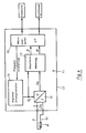
- FIG. 4 shows the block diagram of a circuit 11 suitable for this purpose.
- the electrode arrangement is shown schematically as an impedance Z , which is connected by the connecting lines 9 and 10 to the circuit 11 arranged on a circuit board 12.
- the circuit 11 consists essentially of an impedance measuring circuit 13, a digital sine generator 14, a current / voltage converter 15 and an evaluation circuit in the form of a microcomputer 16.
- the digital sine generator 14 supplies AC voltages U I with the frequencies f 1 and f 2, in which the frequency setting is effected by the microcomputer 16.
- the output of the sine wave generator 14 is connected on the one hand to the current / voltage converter 15 and on the other hand to the impedance measuring circuit 13.
- the current / voltage converter 15 feeds a current I corresponding to the voltage U I into the electrode arrangement with the impedance Z to be determined. Accordingly, the AC voltage U s falling across the electrode arrangement, which is shifted in phase by an angle ⁇ in relation to the voltage U I , is communicated to the input of the impedance measuring circuit 13, which determines the active component of the impedance Z from the ratio U s / U I also determines the phase shift ⁇ . Examples of how such an impedance measurement can be carried out can be found in the europ. Patent application 87 118 435.4. From the active component of the impedance and the phase shift ⁇ , the microcomputer 16 calculates the reactive component of the impedance in a manner known per se and evaluates the active component and the reactive component - as stated above - to output the fill level and water content.
Landscapes
- Physics & Mathematics (AREA)
- Engineering & Computer Science (AREA)
- Power Engineering (AREA)
- General Physics & Mathematics (AREA)
- Thermal Sciences (AREA)
- Fluid Mechanics (AREA)
- Electromagnetism (AREA)
- Chemical & Material Sciences (AREA)
- Health & Medical Sciences (AREA)
- Electrochemistry (AREA)
- Chemical Kinetics & Catalysis (AREA)
- Life Sciences & Earth Sciences (AREA)
- Analytical Chemistry (AREA)
- Biochemistry (AREA)
- General Health & Medical Sciences (AREA)
- Immunology (AREA)
- Pathology (AREA)
- Mechanical Engineering (AREA)
- Transportation (AREA)
- Measurement Of Levels Of Liquids Or Fluent Solid Materials (AREA)
- Investigating Or Analyzing Materials By The Use Of Electric Means (AREA)
Abstract
Description
Die Erfindung geht aus von einem Sensor mit den im Oberbegriff des Anspruchs 1 angegebenen Merkmalen. Ein solcher Sensor ist aus der DE-OS 23 19 008 bekannt. Es handelt sich dabei um einen kapazitiven Niveauschalter zur Kontrolle des Bremsflüssigkeitsniveaus im hydraulischen Bremssystem von Kraftfahrzeugen, der bei Unterschreiten eines vorgegebenen Füllstandes ein Warnsignal abgibt. Der Füllstand, bei dem dieses Warnsignal abgegeben wird, kann dadurch variiert werden, dass der Sensor höhenverstellbar im Bremsflüssigkeitsbehälter angeordnet ist. Mit dem bekannten Sensor kann jedoch nicht der aktuelle Füllstand der Bremsflüssigkeit beobachtet und zur Anzeige gebracht werden.The invention relates to a sensor with the features specified in the preamble of
Vorratsbehälter für die Bremsflüssigkeit in den hydraulischen Bremsanlagen von Kraftfahrzeugen haben üblicherweise eine Belüftungsöffnung. Durch diese Belüftungsöffnung nimmt die Bremsflüssigkeit Luftfeuchtigkeit auf und reichert sich allmählich mit Wasser an. Ein zu hoher Wasseranteil in der Bremsflüssigkeit kann zu einem lebensgefährlichen Versagen der Bremsanlage führen. Es wäre deshalb nützlich, den Wassergehalt der Bremsflüssigkeit zu kennen. Ein Meßfühler zur laufenden Überwachung des Wassergehaltes von Bremsflüssigkeit ist bisher nicht bekannt.Reservoir for the brake fluid in the hydraulic brake systems of motor vehicles usually have a ventilation opening. The brake fluid absorbs air moisture through this ventilation opening and gradually becomes enriched with water. Too much water in the brake fluid can lead to life-threatening failure of the brake system. It would therefore be useful to know the water content of the brake fluid. A sensor for continuously monitoring the water content of brake fluid is not yet known.
Andererseits ist es aus der DE-OS 34 13 135 bekannt, den Wassergehalt von Flüssigkeiten, z.B. von Schmieröl, mittels eines speziellen kapazitiven Sensors zu bestimmen, bei dem zwischen zwei Elektroden eine nichtleitende Membran angeordnet ist, in die die zu untersuchende Flüssigkeit eindringen kann. Dabei wird für die Bestimmung des Wassergehaltes das sich mit dem Wassergehalt ändernde dielektrische Verhalten der Flüssigkeit beobachtet. Dieser bekannte Sensor dient jedoch nicht zur Füllstandsüberwachung.On the other hand, it is known from DE-OS 34 13 135 to determine the water content of liquids, e.g. of lubricating oil to be determined by means of a special capacitive sensor in which a non-conductive membrane is arranged between two electrodes, into which the liquid to be examined can penetrate. For the determination of the water content, the dielectric behavior of the liquid, which changes with the water content, is observed. However, this known sensor is not used for filling level monitoring.
Der Erfindung liegt die Aufgabe zugrunde, eine möglichst einfache, für die Massenproduktion geeignete Möglichkeit zur laufenden Überwachung des Füllstandes und des Wassergehaltes von Bremsflüssigkeit in Kraftfahrzeugen zu schaffen.The invention has for its object to provide the simplest possible, suitable for mass production, for the continuous monitoring of the level and the water content of brake fluid in motor vehicles.
Diese Aufgabe wird gelöst durch einen Sensor mit den im Anspruch 1 angegebenen Merkmalen. Vorteilhafte Weiterbildungen der Erfindung sind Gegenstand der Unteransprüche.This object is achieved by a sensor with the features specified in
Mit dem erfindungsgemäßen Sensor kann sowohl der Füllstand (Niveau) der Bremsflüssigkeit als auch ihr Wassergehalt bestimmt werden, und zwar geschieht das dadurch, dass die komplexe Impedanz des Sensors bei wenigstens zwei unterschiedlichen Frequenzen gemessen und ausgewertet wird.Um das zu verstehen, muss man sich vergegenwärtigen, dass die in die Bremsflüssigkeit eintauchenden Elektroden der angeschlossenen Schaltung eine komplette Impedanz darbieten, die sich als Serienschaltung eines ohmschen Wirkwiderstandes und eines oder zweier kapazitiver Blindwiderstände darstellt. Der ohmsche Wirkwiderstand ist gegeben durch den Widerstand der zwischen den Elektroden stehenden Bremsflüssigkeit. Der kapazitive Blindwiderstand ist bestimmt durch die Kapazität des Kondensators, der durch die mit elektrisch isolierendem Material beschichtete Elektrode, die Bremsflüssigkeit als Gegenelektrode und die elektrisch isolierende Deckschicht als die Dielektrikum gebildet ist. Tragen - wie es bevorzugt wird - beide Elektroden eine solche Deckschicht aus elektrisch isolierendem Material, dann wird der kapazitive Blindwiderstand bestimmt durch die Kapazität der Serienschaltung zweier solcher Kondensatoren mit der Bremsflüssigkeit als gemeinsamer Gegenelektrode.With the sensor according to the invention, both the fill level (level) of the brake fluid and its water content can be determined, and this is done by measuring and evaluating the complex impedance of the sensor at at least two different frequencies realize that in the brake fluid immersing electrodes of the connected circuit present a complete impedance, which is represented as a series connection of an ohmic active resistor and one or two capacitive reactances. The ohmic resistance is given by the resistance of the brake fluid between the electrodes. The capacitive reactance is determined by the capacitance of the capacitor, which is formed by the electrode coated with an electrically insulating material, the brake fluid as the counter electrode and the electrically insulating cover layer as the dielectric. If - as is preferred - both electrodes carry such a cover layer made of electrically insulating material, the capacitive reactance is determined by the capacitance of the series connection of two such capacitors with the brake fluid as a common counter electrode.
Zur Bestimmung des Niveaus der Bremsflüssigkeit wird der kapazitive Blindwiderstand des Sensors gemessen, und zwar am besten mit Hilfe eines Wechselstroms, dessen Frequenz f₁ so niedrig gewählt ist, dass bei dieser Frequenz der kapazitive Blindwert der Impedanz des Sensors groß ist gegen den ohmschen Wirkwiderstand. Da die Abmessungen und die Anordnung der Elektroden sowie das den kapazitiven Blindwiderstand mitbestimmende Dielektrikum (die nicht leitende Deckschicht auf der bzw. den Elektroden) bekannt und konstant sind, hängt der kapazitive Blindwiderstand nur noch von der wirksamen Elektrodenfläche, das ist die eingetauchte Elektrodenfläche, also von der Eintauchtiefe der Elektroden ab. Der gemessene kapazitive Blindwiderstand ist also unmittelbar ein Maß für das Niveau der Bremsflüssigkeit im Vorratsbehälter.To determine the level of the brake fluid, the capacitive reactance of the sensor is measured, best with the help of an alternating current, the frequency of which is chosen so low that at this frequency the capacitive reactance of the impedance of the sensor is large against the ohmic effective resistance. Since the dimensions and the arrangement of the electrodes as well as the dielectric which also determines the capacitive reactance (the non-conductive cover layer on the electrode or electrodes) are known and constant, the capacitive reactance only from the effective electrode area, that is the immersed electrode area, i.e. from the immersion depth of the electrodes. The measured capacitive reactance is therefore a direct measure of the level of the brake fluid in the reservoir.
Zur Messung des Wassergehaltes in der Bremsflüssigkeit wird der ohmsche Wirkwiderstand des Sensors bestimmt, und zwar am besten mit Hilfe eines Wechselstroms, dessen Frequenz f₂ so hoch gewählt ist, dass der bei dieser Frequenz gemessene ohmsche Widerstand groß ist gegen den kapazitiven Widerstand. Dieser ohmsche Wirkwiderstand ist der ohmsche Widerstand der zwischen den beiden Elektroden stehenden Bremsflüssigkeit und wird ausser durch die Abmessungen und die Anordnung der Elektroden bestimmt durch die Eintauchtiefe der Elektroden in die Bremsflüssigkeit und durch den spezifischen Widerstand der Bremsflüssigkeit. Die Abmessungen und Anordnung der beiden Elektroden sind bekannt und konstant, die Eintauchtiefe der Elektroden in die Bremsflüssigkeit ist variabel, aber aus der voraufgegangenen Füllstandsmessung bekannt. Der Quotient aus dem gemessenen Wirkwiderstand und der zuvor bestimmten Eintauchtiefe der Elektroden ist deshalb unmittelbar ein Maß für den spezifischen Widerstand der Bremsflüssigkeit seinerseits hängt in charakteristischer Weise vom Wassergehalt der Bremsflüssigkeit ab. Die Auswerteschaltung kann deshalb aus dem ermittelten spezifischen Widerstand den Wassergehalt bestimmen, vorzugsweise mittels eines Mikrocomputers, der den ermittelten spezifischen Widerstand mit einer ihm vorgegebenen und eingespeicherten Kennlinie vergleicht, die die Abhängigkeit des spezifischen Widerstandes vom Wassergehalt angibt.To measure the water content in the brake fluid, the ohmic effective resistance of the sensor is determined, and best with the help of an alternating current, the frequency f₂ of which is chosen so high that the ohmic resistance measured at this frequency is large against the capacitive resistance. This ohmic resistance is the ohmic resistance of the brake fluid between the two electrodes and is determined by the dimensions and arrangement of the electrodes, the immersion depth of the electrodes in the brake fluid and the specific resistance of the brake fluid. The dimensions and arrangement of the two electrodes are known and constant, the immersion depth of the electrodes in the brake fluid is variable, but is known from the previous level measurement. The quotient of the measured effective resistance and the previously determined immersion depth of the electrodes is therefore a direct measure of the specific resistance of the brake fluid, for its part depends in a characteristic manner on the water content of the brake fluid. The evaluation circuit can therefore determine the water content from the determined specific resistance, preferably by means of a microcomputer, which compares the determined specific resistance with a characteristic curve which is predetermined and stored in it and which indicates the dependence of the specific resistance on the water content.
An den Aufbau und die Art der verwendeten Elektroden sind keine besonderen Anforderungen zu stellen mit Ausnahme der Forderung, dass wenigstens eine der Elektroden eine Deckschicht aus elektrisch isolierendem Material tragen soll, welche den elektrisch leitenden Kern der Elektrode gegenüber der Flüssigkeit isoliert, wobei diese Deckschicht möglichst dicht sein soll, damit die zu überwachende Flüssigkeit darin nicht eindringt und ihre dielektrische Eigenschaft verändert. Besonders geeignet ist eine Anordnung aus einer stabförmigen Elektrode und einer sie koaxial umgebenden rohrförmigen Elektrode, denn eine solche Anordnung ist besonders kompakt und leicht zu handhaben und Schwankungen des Flüssigkeitsspiegels infolge von Fahrbewegungen werden in einer solchen Elektrodenanordnung gedämpft. Die zugehörige Schaltung kann eine hochintegrierte dadurch kompakte und preiswerte elektronische Schaltung sein. Zur Erzeugung der Wechselströme mit den beiden unterschiedlichen Frequenzen verwendet man vorzugsweise einen digital arbeitenden Sinusgenerator, wie er z.B. in der DE-Z Elektronik, Heft 17, 1983, Seiten 52 und 52 oder in der älteren, aber nicht vorveröffentlichten DE-A-36 43 389 beschrieben ist. Für die Impedanzmessung eignet sich besonders ein digital arbeitendes Messgerät, welches in der älteren, aber nicht vorveröffentlichten EP-A-0 271 849 offenbart ist. Dieses Meßgerät hat zur Auswertung der Meßwerte einen Mikrocomputer, der mit Vorteil auch eingesetzt werden kann, um aus den Messwerten Füllstandssignale und Wassergehaltssignale abzuleiten und zur Anzeige zu bringen.There are no special requirements for the structure and type of the electrodes used, with the exception of the requirement that at least one of the electrodes should have a cover layer made of electrically insulating material, which insulates the electrically conductive core of the electrode from the liquid, this cover layer being as possible should be tight so that the liquid to be monitored does not penetrate it and change its dielectric property. An arrangement comprising a rod-shaped electrode and a tubular electrode surrounding it coaxially is particularly suitable, since such an arrangement is particularly compact and easy to handle, and fluctuations in the liquid level as a result of driving movements are dampened in such an electrode arrangement. The associated circuit can be a highly integrated, compact and inexpensive electronic circuit. To generate the alternating currents with the two different frequencies, a digital sine generator is preferably used, as described, for example, in DE-Z Elektronik, number 17, 1983, pages 52 and 52 or in the older, but not previously published DE-A-36 43 389 is described. A digitally operating measuring device, which is disclosed in the older, but not prepublished EP-A-0 271 849, is particularly suitable for the impedance measurement. This measuring device has a microcomputer for evaluating the measured values, which can advantageously also be used to derive level signals and water content signals from the measured values and to display them.
Somit ist der erfindungsgemäße Sensor in seinem Aufbau sehr kompakt und preiswert herzustellen. Er kann ohne Schwierigkeit anstelle eines bislang zur Überwachung des Füllstandes von Bremsflüssigkeit üblichen Niveauschalters eingesetzt werden und liefert nicht nur bei Unterschreiten eines vorgegebenen Niveaus ein Signal, sondern kann den Füllstand über einen größeren Niveaubereich - abhängig von der maximalen Eintauchtiefe der Elektroden - und darüberhinaus den aktuellen Wassergehalt der Bremsflüssigkeit anzeigen.The construction of the sensor according to the invention is thus very compact and inexpensive to manufacture. It can be used without difficulty instead of a level switch that was previously used to monitor the level of brake fluid and not only provides a signal when the level falls below a specified level, but can also fill the level over a larger level range - depending on the maximum immersion depth of the electrodes - and also the current level Display the water content of the brake fluid.
Die Anwendungsmöglichkeiten des erfindungsgemäßen Sensors sind nicht auf die Überwachung von Bremsflüssigkeit beschränkt, er kann vielmehr überall dort eingesetzt werden, wo es darum geht, zumindest schwach leitende ineinander mischbare Flüssigkeiten hinsichtlich ihres Mischungsverhältnisses oder eine sich in ihrem spezifischen Widerstand verändernde Flüssigkeit hinsichtlich ihres Zustandes und des Füllstandes zu überwachen.The possible applications of the sensor according to the invention are not limited to the monitoring of brake fluid, it can rather be used wherever it is a question of at least weakly conductive intermiscible liquids with regard to their mixing ratio or a liquid which changes in its specific resistance with regard to its condition and Monitor fill level.
Der weiteren Erläuterung der Erfindung dienen die beigefügten Zeichnungen:
Figur 1 zeigt schematisch im Vertikalschnitt die Anordnung des Elektrodenpaares eines Sensors in einem Vorratsbehälter für Bremsflüssigkeit,Figur 2 zeigt im Detail vergrößert einen Längsschnitt durch das Elektrodenpaar aus Fig. 1,Figur 3 zeigt ein Ersatzschaltbild des Sensors, und- Figur 4 zeigt ein Blockschaltbild des Sensors.
- FIG. 1 shows schematically in vertical section the arrangement of the pair of electrodes of a sensor in a reservoir for brake fluid,
- FIG. 2 shows in detail an enlarged longitudinal section through the pair of electrodes from FIG. 1,
- Figure 3 shows an equivalent circuit diagram of the sensor, and
- Figure 4 shows a block diagram of the sensor.
Figur 1 zeigt einen Vorratsbehälter 1, der bis zu einem Niveau 2 mit einer Bremsflüssigkeit angefüllt ist. Der Vorratsbehälter 1 hat auf seiner Oberseite einen Einfüllstutzen 3, der durch einen Deckel 4 verschlossen ist. Der Deckel 4 besteht aus einem elektrisch isolierenden Kunststoff und trägt an seiner Unterseite zwei Elektroden 5 und 6. Die Elektrode 5 ist eine stabförmige Innenelektrode und die Elektrode 6 ist eine rohrförmige, die Innenelektrode 5 koaxial umgebende Aussenelektrode. Beide Elektroden bestehen aus Titan und tragen eine Deckschicht 7 bzw. 8 aus Titandioxid, welche dadurch gebildet werden kann, dass man das Titan an Luft oxidieren läßt. Die Deckschichten 7 und 8 sind leitend und so dicht, dass sie keine Bremsflüssigkeit ein dringen lassen. Elektrisch leitend ist nur der nicht oxidierte Kern 5a bzw. 6a der Elektroden. Die Elektroden tauchen beide in die Bremsflüssigkeit ein. Die Elektroden 5 und 6 sind mit je einer elektrischen Leitung 9 bzw. 10 verbunden, welche durch den Deckel 4 hindurchgeführt sind und zu einer elektronischen Schaltung 11 führen.Figure 1 shows a
In einem praktisch ausgeführten Beispiel hat die Innenelektrode 5 einen Durchmesser von 4 mm, die Außenelektrode 6 einen Innendurchmesser von 10 mm; beide Elektroden sind 40 mm lang und ihre Deckschicht 7 bzw. 8 aus Titan ist wenige µm dick. Damit lassen sich Eintauchtiefen zwischen 10 mm und 25 mm sowie Wassergehalte in Bremsflüssigkeit von weniger als 0,05 % bestimmen.In a practical example, the
Die Figur 3 zeigt das Ersatzschaltbild dieser Anordnung. Es besteht aus eben dieser Schaltung 11 sowie aus zwei Kapazitäten C1 und C2 und einem ohmschen Widerstand R in Serienschaltung. Die Schaltung 11 dient zur Bestimmung der komplexen Impedanz
Die Kapazität C1 ist die Kapazität des Kondensators, der gebildet wird durch den Kern 5a der Innenelektrode als erster Elektrode, der in der Elektrodenanordnung bis zum Niveau 2 stehenden Bremsflüssigkeit als Gegenelektrode und der Deckschicht 7 als Dielektrikum. Die Kapazität C2 ist die Kapazität des Kondensators, der durch den Kern 6a der äußeren Elektrode als erster Elektrode, durch die bis zum Niveau 2 stehende Bremsflüssigkeit als Gegenelektrode und durch die Deckschicht 8 als Dielektrikum gebildet wird. R ist der ohmsche Widerstand der in der Aussenelektrode stehenden Bremsflüssigkeit.The capacitance C1 is the capacitance of the capacitor, which is formed by the
Bei der gegebenen Elektrodenanordnung hängt die Kapazität C1 + C2 allein von der wirksamen Elektrodenfläche, das ist die von der Bremsflüssigkeit benetzte Oberfläche der Elektroden 5 und 6, also nur von der Eintauchtiefe der Elektroden 5 und 6 in die Bremsflüssigkeit ab.In the given electrode arrangement, the capacitance C1 + C2 depends solely on the effective electrode area, that is the surface of the
Bei derselben gegebenen Anordnung hängt der ohmsche Widerstand R von der Eintauchtiefe der Elektroden in die Bremsflüssigkeit und von deren aktuellem spezifischem Widerstand ab.With the same given arrangement, the ohmic resistance R depends on the immersion depth of the electrodes in the brake fluid and on their current specific resistance.
C1 + C2 wird bestimmt, indem die Elektrodenanordnung mit einem Wechselstrom gespeist wird, dessen Frequenz f₁ so niedrig ist, dass der kapazitive Blindwiderstand
Der Wirkwiderstand R wird bestimmt, indem die Elektrodenanordnung mit einem Wechselstrom gespeist wird, dessen Frequenz f₂ so groß ist, dass der Wirkwiderstand R groß ist gegen den kapazitiven Blindwiderstand. Der Wirkwiderstand R ist um so kleiner, je größer die Eintauchtiefe der Elektroden 5 und 6 ist. In erster Näherung ist der Wirkwiderstand R der Eintauchtiefe umgekehrt proportional. Aus dem gemessenen Wirkwiderstand und der zuvor bei der Frequenz f₁ bestimmten Eintauchtiefe läßt sich deshalb der spezifische Widerstand der Bremsflüssigkeit bestimmen. Der spezifische Widerstand der Bremsflüssigkeit ist abhängig von ihrem Wassergehalt; die Abhängigkeit ist bekannt bzw. kann für eine gegebene Bremsflüssigkeit empirisch ermittelt werden. Durch Vergleich des gemessenen spezifischen Widerstandes mit der bekannten bzw. empirisch ermittelten Kennlinie, die die Abhängigkeit des spezifischen Widerstandes vom Wassergehalt angibt, kann somit der Wassergehalt ermittelt und angezeigt werden. Diese Auswertung geschieht am einfachsten mit Hilfe eines Mikrocomputers.The active resistance R is determined by feeding the electrode arrangement with an alternating current, the
Figur 4 zeigt das Blockschaltbild einer dazu geeigneten Schaltung 11. Die Elektrodenanordnung ist schematisch als eine Impedanz Z dargestellt, welche durch die Anschlußleitungen 9 und 10 mit der auf einer Platine 12 angeordneten Schaltung 11 verbunden ist. Die Schaltung 11 besteht im wesentlichen aus einer Impedanzmeßschaltung 13, aus einem digitalen Sinusgenerator 14, aus einem Strom/Spannungs-Wandler 15 und aus einer Auswerteschaltung in Gestalt eines Mikrocomputers 16. Der digitale Sinusgenerator 14 liefert Wechselspannungen UI mit den Frequenzen f₁ und f₂ , wobei die Frequenzeinstellung durch den Mikrocomputer 16 bewirkt wird. Der Ausgang des Sinusgenerators 14 ist einerseits mit dem Strom/Spannungs-Wandler 15 und andererseits mit der Impedanzmeßschaltung 13 verbunden. Der Strom/Spannungs-Wandler 15 speist in die Elektrodenanordnung mit der zu bestimmenden Impedanz Z einen der Spannung UI entsprechenden Strom I ein. Die dementsprechend an der Elektrodenanordnung abfallende Wechselspannung Us , welche gegenüber der Spannung UI um den Winkel φ in der Phase verschoben ist, wird dem Eingang der Impedanzmeßschaltung 13 mitgeteilt, die aus dem Verhältnis Us /UI die Wirkkomponente der Impedanz Z ermittelt und auch die Phasenverschiebung φ bestimmt. Beispiele, wie eine solche Impedanzmessung durchgeführt werden kann, finden sich in der europ. Patentanmeldung 87 118 435.4. Aus der Wirkkomponente der Impedanz und der Phasenverschiebung φ errechnet der Mikrocomputer 16 auf an sich bekannte Weise die Blindkomponente der Impedanz und wertet die Wirkkomponente und die Blindkomponente - wie oben angegeben - zur Ausgabe von Füllstand und Wassergehalt aus.FIG. 4 shows the block diagram of a
Claims (7)
und dass die elektrische Schaltung (11) eine Impedanzmeßschaltung (13), welche bei wenigstens zwei unterschiedlichen Frequenzen die komplexe Impedanz des Sensors nach Realteil (ohmscher Wirkwiderstand) und Imaginärteil (kapazitiver Blindwiderstand) ermittelt,
sowie eine Auswerteschaltung (16) umfaßt, welche aus dem frequenzabhängigen Verlauf von Real- und Imaginärteil der Impedanz das Niveau (2) der Flüssigkeit und z.B. über den spezifischen Widerstand der Flüssigkeit den Wassergehalt oder eine andere den spezifischen Widerstand mitbestimmende Zustandsgröße der Flüssigkeit bestimmt.1. Capacitive sensor for determining the level of an at least weakly electrically conductive fluid in a container, in particular for determining the level of the brake fluid in the hydraulic brake system of motor vehicles, consisting of two electrodes intended for immersion in the fluid and an active circuit which connects the electrodes to one another connects, characterized in that at least one of the two electrodes (5, 6) has a cover layer (7, 8) made of electrical carries insulating material which insulates the electrically conductive core (5a, 6a) of the electrode (5, 6) from the liquid,
and that the electrical circuit (11) is an impedance measuring circuit (13) which determines the complex impedance of the sensor according to the real part (ohmic effective resistance) and imaginary part (capacitive reactance) at at least two different frequencies,
as well as an evaluation circuit (16) which determines the level (2) of the liquid from the frequency-dependent course of the real and imaginary part of the impedance and, for example, the water content or another state variable of the liquid which also determines the specific resistance.
und dass die Auswerteschaltung (16) aus dem bei der niedrigeren Frequenz f₁ ermittelten Blindwiderstand das Niveau (2) der Flüssigkeit bestimmt und aus dem bei der höheren Frequenz f₂ ermittelten Wirkwiderstand unter Berücksichtigung des bestimmten Niveaus (2) den spezifischen Widerstand der Flüssigkeit bestimmt.2. Sensor according to claim 1, characterized in that the impedance measuring circuit measures the impedance at two different frequencies f₁ and f₂, the frequency f₁ being chosen so low that the capacitive reactance of the impedance measured by it is large against the ohmic resistance and the Frequency f₂ is chosen so high that the ohmic effective resistance of the impedance measured by it is large compared to the capacitive reactance,
and that the evaluation circuit (16) determines the level (2) of the liquid from the reactance determined at the lower frequency f 1 and from the f 2 at the higher frequency determined resistance, taking into account the specific level (2) determines the specific resistance of the liquid.
Applications Claiming Priority (2)
| Application Number | Priority Date | Filing Date | Title |
|---|---|---|---|
| DE3812687A DE3812687A1 (en) | 1988-04-16 | 1988-04-16 | CAPACITIVE SENSOR FOR DETERMINING THE LEVEL OF A LIQUID IN A CONTAINER |
| DE3812687 | 1988-04-16 |
Publications (3)
| Publication Number | Publication Date |
|---|---|
| EP0338400A2 true EP0338400A2 (en) | 1989-10-25 |
| EP0338400A3 EP0338400A3 (en) | 1991-02-06 |
| EP0338400B1 EP0338400B1 (en) | 1994-08-10 |
Family
ID=6352117
Family Applications (1)
| Application Number | Title | Priority Date | Filing Date |
|---|---|---|---|
| EP89106489A Expired - Lifetime EP0338400B1 (en) | 1988-04-16 | 1989-04-12 | Capacitive sensor for determining the liquid level in a container |
Country Status (2)
| Country | Link |
|---|---|
| EP (1) | EP0338400B1 (en) |
| DE (2) | DE3812687A1 (en) |
Cited By (22)
| Publication number | Priority date | Publication date | Assignee | Title |
|---|---|---|---|---|
| WO1996024030A1 (en) * | 1995-02-02 | 1996-08-08 | Abbott Laboratories | Volume verification apparatus and method |
| WO1998012513A1 (en) * | 1996-09-17 | 1998-03-26 | Pharmacia & Upjohn Ab | Device for detection of when a test probe gets into contact with a liquid surface |
| EP0856724A1 (en) * | 1997-01-31 | 1998-08-05 | Canon Kabushiki Kaisha | Method and device for determining the quantity of product present in a reservoir, a product resevoir and a device for processing electrical signals intended for such a determination device |
| FR2765334A1 (en) * | 1997-06-27 | 1998-12-31 | Canon Kk | Supervising the operational state of ink reservoir |
| US6408693B1 (en) | 2000-10-04 | 2002-06-25 | Arthur G. Drinkwater | Fluid level indicating device for any container |
| EP1255107A2 (en) * | 2001-05-04 | 2002-11-06 | Delphi Technologies, Inc. | Oil level and condition sensor |
| WO2003046490A1 (en) * | 2001-11-27 | 2003-06-05 | Endress + Hauser Gmbh+Co. Kg | Method for a capacitive level measurement |
| WO2003050479A1 (en) * | 2001-12-12 | 2003-06-19 | Endress + Hauser Gmbh + Co.Kg | Electronic field device with a sensor unit for process measurement |
| WO2003050480A1 (en) * | 2001-12-12 | 2003-06-19 | Endress + Hauser Gmbh + Co. Kg | Electronic field device with a sensor unit for capacitive level measurement in a container |
| EP1400787A1 (en) * | 2002-09-17 | 2004-03-24 | Nanmat Technology Co., Ltd. | Method for detecting quantity variation of high purity liquid chemicals and devices to carry out the method |
| WO2004102133A2 (en) * | 2003-05-16 | 2004-11-25 | Endress+Hauser Gmbh+Co. Kg | Capacitance level measurement |
| DE202007014056U1 (en) | 2007-10-09 | 2008-12-18 | A.B.S. Silo- und Förderanlagen GmbH | Level gauge for flexible silos |
| DE202007014057U1 (en) | 2007-10-09 | 2008-12-18 | Delox Elektronik Gmbh | Level measuring device for solid containers |
| US7555394B2 (en) | 2003-09-17 | 2009-06-30 | Analog Devices, Inc. | Measuring circuit and a method for determining a characteristic of the impedance of a complex impedance element for facilitating characterization of the impedance thereof |
| EP2238440A2 (en) * | 2008-01-09 | 2010-10-13 | DirAction, LLC | Automated phase separation and fuel quality sensor |
| CN102052951A (en) * | 2010-11-12 | 2011-05-11 | 天津大学 | Measurement device and method for multi-phase interface liquid level based on dual-modality sensor |
| FR2958605A1 (en) * | 2010-04-09 | 2011-10-14 | Peugeot Citroen Automobiles Sa | Control device for braking system of vehicle, has tank storing brake fluid, and monitoring units adapted to identify rise in level of liquid in tank and generate alarm if identified rise is higher than given maximum threshold |
| WO2012093242A1 (en) * | 2011-01-04 | 2012-07-12 | Avelec Limited | Fluid level sensor apparatus |
| EP2619529A4 (en) * | 2010-09-24 | 2017-03-22 | The Marketing Store Worldwide, LP | Non-contact liquid sensing device |
| US10082546B2 (en) | 2006-12-11 | 2018-09-25 | Quasar Federal Systems | Compact underwater electromagnetic measurement system using magnetic sensors and electrical sensors having capacitive electrodes |
| EP3816591A1 (en) * | 2019-10-28 | 2021-05-05 | Robert Bosch GmbH | Container device, vehicle |
| DE102022209515A1 (en) | 2022-09-12 | 2024-03-14 | Knipping Kunststofftechnik Gessmann Gmbh | Level measurement sensor |
Families Citing this family (18)
| Publication number | Priority date | Publication date | Assignee | Title |
|---|---|---|---|---|
| DE4023336A1 (en) * | 1990-07-23 | 1992-02-06 | Hessberg Sigfried | DEVICE FOR MONITORING BODY LIQUID LEAKING FROM A CATHETER |
| DE4105857C2 (en) * | 1991-02-25 | 1994-07-07 | Claas Ohg | Device for measuring a mass flow |
| DE19528384C2 (en) * | 1995-08-02 | 1999-09-30 | Ulrich Pok | Capacitive measuring device for continuous level control for media with different dielectric constants |
| DE29613141U1 (en) * | 1996-07-29 | 1996-09-19 | Gattringer Michael | Level sensor |
| WO1998033044A1 (en) | 1997-01-28 | 1998-07-30 | Abb Research Ltd. | Capacitative level detector with optimized electrode geometry |
| DE19713267A1 (en) * | 1997-01-28 | 1998-07-30 | Abb Research Ltd | Method for determining the dielectric constant and / or the conductivity of at least one medium and device for carrying out the method |
| DE19755418A1 (en) * | 1997-12-12 | 1999-06-24 | Fraunhofer Ges Forschung | Sensor measuring complex impedances |
| DE19755417C2 (en) * | 1997-12-12 | 1999-11-04 | Fraunhofer Ges Forschung | Evaluation circuit for determining complex impedances, device for measuring complex impedances and use of the device |
| DE19757190A1 (en) * | 1997-12-22 | 1999-06-24 | Abb Research Ltd | Capacitive level sensor with integrated dirt film detection |
| DE19851213C1 (en) * | 1998-11-06 | 2000-06-08 | Daimler Chrysler Ag | Capacitive sensor arrangement for a liquid or gaseous medium acting as a dielectric |
| US7134330B2 (en) | 2003-05-16 | 2006-11-14 | Endress + Hauser Gmbh + Co. Kg | Capacitive fill level meter |
| DE102005027344A1 (en) | 2005-06-13 | 2007-01-04 | Ifm Electronic Gmbh | Capacitive level measuring or detection device |
| DE102008006931A1 (en) | 2008-01-31 | 2009-08-13 | Daimler Ag | Sensor for detecting a level of a liquid in a container and fuel cell system with such a sensor |
| DE202011101482U1 (en) * | 2011-06-06 | 2012-09-07 | Robert Seuffer Gmbh & Co. Kg | Device for detecting material properties |
| DE202012000569U1 (en) | 2012-01-20 | 2013-04-23 | Seuffer Gmbh & Co.Kg | Sensor device for detecting liquid properties |
| DE102016009879A1 (en) * | 2016-08-10 | 2018-02-15 | Tedrive Steering Systems Gmbh | Method and device for determining the leakage rate of a hydraulic component of a vehicle and its remaining range |
| DE102019210123A1 (en) * | 2019-07-09 | 2021-01-14 | Zf Friedrichshafen Ag | System and method for detecting an oil condition |
| DE102021115222A1 (en) * | 2021-06-11 | 2022-12-15 | Kyocera Avx Components (Werne) Gmbh | Sensor device and method for detecting properties of a liquid |
Citations (7)
| Publication number | Priority date | Publication date | Assignee | Title |
|---|---|---|---|---|
| NL6714416A (en) * | 1966-10-26 | 1968-04-29 | ||
| DE2319008A1 (en) * | 1973-04-14 | 1974-10-31 | Friedrich Mahne | ARRANGEMENT FOR CHECKING THE BRAKE FLUID LEVEL IN MOTOR VEHICLE BRAKING SYSTEMS |
| NL7603909A (en) * | 1976-04-13 | 1977-10-17 | Mattheus Gijsbertus Jozef Arts | Fluid level measuring catheter - has oblong body with measuring devices at end connected to gauges |
| DE3322657A1 (en) * | 1983-06-23 | 1985-01-10 | VEGA Grieshaber GmbH & Co, 7620 Wolfach | Device for monitoring an elongated probe, which is provided for capacitive level measurement in a container, for cracking |
| WO1985004718A1 (en) * | 1984-04-06 | 1985-10-24 | Fraunhofer-Gesellschaft Zur Förderung Der Angewand | Measuring probe for the analysis of liquids |
| EP0271849A2 (en) * | 1986-12-19 | 1988-06-22 | DODUCO KG. Dr. Eugen Dürrwächter | Instrument for measuring the impedance for determining the change of the impedance of a capacitive sensor by dipping in a fluid |
| EP0288215A2 (en) * | 1987-04-24 | 1988-10-26 | Simmonds Precision Products Inc. | Determination of electrical capacitance and resistance |
Family Cites Families (3)
| Publication number | Priority date | Publication date | Assignee | Title |
|---|---|---|---|---|
| CH521574A (en) * | 1970-12-08 | 1972-04-15 | Endress Hauser Gmbh Co | Level measuring device |
| DE2521687C3 (en) * | 1975-05-15 | 1980-04-30 | Endress U. Hauser Gmbh U. Co, 7867 Maulburg | Measuring transducer for capacitive level measurement |
| CH632089A5 (en) * | 1978-06-15 | 1982-09-15 | Alusuisse | Filling level measuring probe for an electrically conductive medium |
-
1988
- 1988-04-16 DE DE3812687A patent/DE3812687A1/en not_active Withdrawn
-
1989
- 1989-04-12 DE DE58908161T patent/DE58908161D1/en not_active Expired - Fee Related
- 1989-04-12 EP EP89106489A patent/EP0338400B1/en not_active Expired - Lifetime
Patent Citations (7)
| Publication number | Priority date | Publication date | Assignee | Title |
|---|---|---|---|---|
| NL6714416A (en) * | 1966-10-26 | 1968-04-29 | ||
| DE2319008A1 (en) * | 1973-04-14 | 1974-10-31 | Friedrich Mahne | ARRANGEMENT FOR CHECKING THE BRAKE FLUID LEVEL IN MOTOR VEHICLE BRAKING SYSTEMS |
| NL7603909A (en) * | 1976-04-13 | 1977-10-17 | Mattheus Gijsbertus Jozef Arts | Fluid level measuring catheter - has oblong body with measuring devices at end connected to gauges |
| DE3322657A1 (en) * | 1983-06-23 | 1985-01-10 | VEGA Grieshaber GmbH & Co, 7620 Wolfach | Device for monitoring an elongated probe, which is provided for capacitive level measurement in a container, for cracking |
| WO1985004718A1 (en) * | 1984-04-06 | 1985-10-24 | Fraunhofer-Gesellschaft Zur Förderung Der Angewand | Measuring probe for the analysis of liquids |
| EP0271849A2 (en) * | 1986-12-19 | 1988-06-22 | DODUCO KG. Dr. Eugen Dürrwächter | Instrument for measuring the impedance for determining the change of the impedance of a capacitive sensor by dipping in a fluid |
| EP0288215A2 (en) * | 1987-04-24 | 1988-10-26 | Simmonds Precision Products Inc. | Determination of electrical capacitance and resistance |
Non-Patent Citations (2)
| Title |
|---|
| JOURNAL OF PHYSICS E. SCIENTIFIC INSTRUMENTS. vol. 16, no. 9, September 1983, ISHING, BRISTOL GB Seiten 827 - 828; P.I. ROSS: "A WATER-LEVEL SENSOR USING A CAPACITANCE TO FREQUENCY CONVERTER" * |
| MEASUREMENT AND CONTROL. vol. 21, no. 1, Februar 1988, LONDON GB Seiten 15 - 19; N. WATMOUGH: "CAPACITANCE FOR LEVEL MEASUREMENT" * |
Cited By (33)
| Publication number | Priority date | Publication date | Assignee | Title |
|---|---|---|---|---|
| WO1996024030A1 (en) * | 1995-02-02 | 1996-08-08 | Abbott Laboratories | Volume verification apparatus and method |
| WO1998012513A1 (en) * | 1996-09-17 | 1998-03-26 | Pharmacia & Upjohn Ab | Device for detection of when a test probe gets into contact with a liquid surface |
| US6328934B1 (en) | 1996-09-17 | 2001-12-11 | Pharmacia Ab | Device for detection of when a test probe gets into contact with a liquid surface |
| EP0856724A1 (en) * | 1997-01-31 | 1998-08-05 | Canon Kabushiki Kaisha | Method and device for determining the quantity of product present in a reservoir, a product resevoir and a device for processing electrical signals intended for such a determination device |
| FR2759165A1 (en) * | 1997-01-31 | 1998-08-07 | Canon Kk | METHOD AND DEVICE FOR DETERMINING THE QUANTITY OF PRODUCT PRESENT IN A TANK, PRODUCT TANK AND ELECTRIC SIGNAL PROCESSING DEVICE FOR SUCH A DETERMINATION DEVICE |
| US6345532B1 (en) | 1997-01-31 | 2002-02-12 | Canon Kabushiki Kaisha | Method and device for determining the quantity of product present in a reservoir, a product reservoir and a device for processing electrical signals intended for such a determination device |
| FR2765334A1 (en) * | 1997-06-27 | 1998-12-31 | Canon Kk | Supervising the operational state of ink reservoir |
| US6164744A (en) * | 1997-06-27 | 2000-12-26 | Canon Kabushiki Kaisha | Method and device for monitoring the operational state of a reservoir, for example an ink reservoir |
| US6408693B1 (en) | 2000-10-04 | 2002-06-25 | Arthur G. Drinkwater | Fluid level indicating device for any container |
| EP1255107A2 (en) * | 2001-05-04 | 2002-11-06 | Delphi Technologies, Inc. | Oil level and condition sensor |
| WO2003046490A1 (en) * | 2001-11-27 | 2003-06-05 | Endress + Hauser Gmbh+Co. Kg | Method for a capacitive level measurement |
| CN1293365C (en) * | 2001-12-12 | 2007-01-03 | 恩德莱斯和豪瑟尔两合公司 | Electronic field device with a sensor unit for capacitive level measurement in a container |
| WO2003050480A1 (en) * | 2001-12-12 | 2003-06-19 | Endress + Hauser Gmbh + Co. Kg | Electronic field device with a sensor unit for capacitive level measurement in a container |
| WO2003050479A1 (en) * | 2001-12-12 | 2003-06-19 | Endress + Hauser Gmbh + Co.Kg | Electronic field device with a sensor unit for process measurement |
| US7415366B2 (en) | 2001-12-12 | 2008-08-19 | Endress + Hauser Gmbh + Co. Kg | Electronic field device with a sensor unit for capacitive level measurement in a container |
| EP1400787A1 (en) * | 2002-09-17 | 2004-03-24 | Nanmat Technology Co., Ltd. | Method for detecting quantity variation of high purity liquid chemicals and devices to carry out the method |
| WO2004102133A2 (en) * | 2003-05-16 | 2004-11-25 | Endress+Hauser Gmbh+Co. Kg | Capacitance level measurement |
| WO2004102133A3 (en) * | 2003-05-16 | 2005-02-10 | Endress & Hauser Gmbh & Co Kg | Capacitance level measurement |
| CN100432636C (en) * | 2003-05-16 | 2008-11-12 | 恩德莱斯和豪瑟尔两合公司 | Capacitance level measurement |
| CN100541207C (en) * | 2003-09-17 | 2009-09-16 | 阿纳洛格装置公司 | The characteristic of impedance of determining complex impedance element is so that the metering circuit of the sign of its impedance and method |
| US7555394B2 (en) | 2003-09-17 | 2009-06-30 | Analog Devices, Inc. | Measuring circuit and a method for determining a characteristic of the impedance of a complex impedance element for facilitating characterization of the impedance thereof |
| US10082546B2 (en) | 2006-12-11 | 2018-09-25 | Quasar Federal Systems | Compact underwater electromagnetic measurement system using magnetic sensors and electrical sensors having capacitive electrodes |
| DE202007014056U1 (en) | 2007-10-09 | 2008-12-18 | A.B.S. Silo- und Förderanlagen GmbH | Level gauge for flexible silos |
| DE202007014057U1 (en) | 2007-10-09 | 2008-12-18 | Delox Elektronik Gmbh | Level measuring device for solid containers |
| EP2238440A4 (en) * | 2008-01-09 | 2013-11-20 | Diraction Llc | Automated phase separation and fuel quality sensor |
| EP2238440A2 (en) * | 2008-01-09 | 2010-10-13 | DirAction, LLC | Automated phase separation and fuel quality sensor |
| FR2958605A1 (en) * | 2010-04-09 | 2011-10-14 | Peugeot Citroen Automobiles Sa | Control device for braking system of vehicle, has tank storing brake fluid, and monitoring units adapted to identify rise in level of liquid in tank and generate alarm if identified rise is higher than given maximum threshold |
| EP2619529A4 (en) * | 2010-09-24 | 2017-03-22 | The Marketing Store Worldwide, LP | Non-contact liquid sensing device |
| CN102052951B (en) * | 2010-11-12 | 2012-07-04 | 天津大学 | Measurement device and method for multi-phase interface liquid level based on dual-modality sensor |
| CN102052951A (en) * | 2010-11-12 | 2011-05-11 | 天津大学 | Measurement device and method for multi-phase interface liquid level based on dual-modality sensor |
| WO2012093242A1 (en) * | 2011-01-04 | 2012-07-12 | Avelec Limited | Fluid level sensor apparatus |
| EP3816591A1 (en) * | 2019-10-28 | 2021-05-05 | Robert Bosch GmbH | Container device, vehicle |
| DE102022209515A1 (en) | 2022-09-12 | 2024-03-14 | Knipping Kunststofftechnik Gessmann Gmbh | Level measurement sensor |
Also Published As
| Publication number | Publication date |
|---|---|
| DE3812687A1 (en) | 1989-10-26 |
| DE58908161D1 (en) | 1994-09-15 |
| EP0338400B1 (en) | 1994-08-10 |
| EP0338400A3 (en) | 1991-02-06 |
Similar Documents
| Publication | Publication Date | Title |
|---|---|---|
| EP0338400B1 (en) | Capacitive sensor for determining the liquid level in a container | |
| EP1348108A1 (en) | Method and device for measuring levels | |
| DE2515065C2 (en) | Standing height measuring device for liquid containers | |
| DE2645716C2 (en) | Device for continuous measurement of the liquid level in a container | |
| EP1204848B1 (en) | Method for measuring level and level sensor | |
| DE3714306A1 (en) | CAPACITIVE LEVEL INDICATOR | |
| DE19645970C2 (en) | Capacitive level sensor for detecting the level of a fluid located in a container | |
| DE19949985A1 (en) | Capacitive sensor for the detection of the level of a medium in a container | |
| WO1996035929A1 (en) | Capacitive level sensor | |
| DE3114678C2 (en) | Level indicator for electrically conductive liquids and bulk goods | |
| DE102010030362A1 (en) | Device for capacitive determining of filling level of liquid in container, has sensor electrode, protective electrode and control unit that impinges sensor electrode with control signal | |
| DE19816455A1 (en) | Level sensor for fuel tank | |
| DE3524250A1 (en) | ARRANGEMENT FOR CHECKING THE LEVEL OF AN INK TANK | |
| DE4025400C1 (en) | ||
| DE10063557B4 (en) | Method and device for measuring water levels | |
| DE2819731C2 (en) | Arrangement for capacitive level measurement in a container | |
| EP0679863B2 (en) | Device for measuring the position of a conductor of a cable within a cable covering | |
| EP0621466A1 (en) | System for capacitive level measurement and its use | |
| EP1521066A1 (en) | Capacitive level measuring system | |
| DE10309769B4 (en) | Arrangement for determining state variables for liquids in a closed non-metallic container | |
| EP0927877B1 (en) | A measuring device for a fuel gauge | |
| DE1498404A1 (en) | Capacitive measuring probe for determining the level of liquids and solid goods with a limited expansion of the electric field | |
| EP1521065A1 (en) | Method for measuring the filling level in a container and a corresponding level measuring device | |
| DE3422394C2 (en) | ||
| EP0724140B1 (en) | Method and device for signal evaluation of a capacitive filling level sensor |
Legal Events
| Date | Code | Title | Description |
|---|---|---|---|
| PUAI | Public reference made under article 153(3) epc to a published international application that has entered the european phase |
Free format text: ORIGINAL CODE: 0009012 |
|
| AK | Designated contracting states |
Kind code of ref document: A2 Designated state(s): DE ES FR GB IT SE |
|
| PUAL | Search report despatched |
Free format text: ORIGINAL CODE: 0009013 |
|
| AK | Designated contracting states |
Kind code of ref document: A3 Designated state(s): DE ES FR GB IT SE |
|
| 17P | Request for examination filed |
Effective date: 19901227 |
|
| 17Q | First examination report despatched |
Effective date: 19920320 |
|
| GRAA | (expected) grant |
Free format text: ORIGINAL CODE: 0009210 |
|
| AK | Designated contracting states |
Kind code of ref document: B1 Designated state(s): DE ES FR GB IT SE |
|
| PG25 | Lapsed in a contracting state [announced via postgrant information from national office to epo] |
Ref country code: IT Free format text: LAPSE BECAUSE OF FAILURE TO SUBMIT A TRANSLATION OF THE DESCRIPTION OR TO PAY THE FEE WITHIN THE PRE;WARNING: LAPSES OF ITALIAN PATENTS WITH EFFECTIVE DATE BEFORE 2007 MAY HAVE OCCURRED AT ANY TIME BEFORE 2007. THE CORRECT EFFECTIVE DATE MAY BE DIFFERENT FROM THE ONE RECORDED.SCRIBED TIME-LIMIT Effective date: 19940810 Ref country code: ES Free format text: THE PATENT HAS BEEN ANNULLED BY A DECISION OF A NATIONAL AUTHORITY Effective date: 19940810 Ref country code: GB Effective date: 19940810 Ref country code: FR Effective date: 19940810 |
|
| REF | Corresponds to: |
Ref document number: 58908161 Country of ref document: DE Date of ref document: 19940915 |
|
| PG25 | Lapsed in a contracting state [announced via postgrant information from national office to epo] |
Ref country code: SE Effective date: 19941110 |
|
| EN | Fr: translation not filed | ||
| GBV | Gb: ep patent (uk) treated as always having been void in accordance with gb section 77(7)/1977 [no translation filed] |
Effective date: 19940810 |
|
| PLBI | Opposition filed |
Free format text: ORIGINAL CODE: 0009260 |
|
| 26 | Opposition filed |
Opponent name: VDO ADOLF SCHINDLING AG Effective date: 19950505 |
|
| PLBF | Reply of patent proprietor to notice(s) of opposition |
Free format text: ORIGINAL CODE: EPIDOS OBSO |
|
| PLBF | Reply of patent proprietor to notice(s) of opposition |
Free format text: ORIGINAL CODE: EPIDOS OBSO |
|
| PLBF | Reply of patent proprietor to notice(s) of opposition |
Free format text: ORIGINAL CODE: EPIDOS OBSO |
|
| RAP2 | Party data changed (patent owner data changed or rights of a patent transferred) |
Owner name: DODUCO GMBH + CO DR. EUGEN DUERRWAECHTER I.K. |
|
| GRAH | Despatch of communication of intention to grant a patent |
Free format text: ORIGINAL CODE: EPIDOS IGRA |
|
| PLBO | Opposition rejected |
Free format text: ORIGINAL CODE: EPIDOS REJO |
|
| RAP2 | Party data changed (patent owner data changed or rights of a patent transferred) |
Owner name: DODUCO GMBH |
|
| PLBN | Opposition rejected |
Free format text: ORIGINAL CODE: 0009273 |
|
| STAA | Information on the status of an ep patent application or granted ep patent |
Free format text: STATUS: OPPOSITION REJECTED |
|
| 27O | Opposition rejected |
Effective date: 19980122 |
|
| PGFP | Annual fee paid to national office [announced via postgrant information from national office to epo] |
Ref country code: DE Payment date: 19990422 Year of fee payment: 11 |
|
| PG25 | Lapsed in a contracting state [announced via postgrant information from national office to epo] |
Ref country code: DE Free format text: LAPSE BECAUSE OF NON-PAYMENT OF DUE FEES Effective date: 20010201 |