EP0340053B2 - Shoe sole for sporting and outdoor activities - Google Patents
Shoe sole for sporting and outdoor activities Download PDFInfo
- Publication number
- EP0340053B2 EP0340053B2 EP89400805A EP89400805A EP0340053B2 EP 0340053 B2 EP0340053 B2 EP 0340053B2 EP 89400805 A EP89400805 A EP 89400805A EP 89400805 A EP89400805 A EP 89400805A EP 0340053 B2 EP0340053 B2 EP 0340053B2
- Authority
- EP
- European Patent Office
- Prior art keywords
- protuberances
- sole according
- layer
- rigid
- sole
- Prior art date
- Legal status (The legal status is an assumption and is not a legal conclusion. Google has not performed a legal analysis and makes no representation as to the accuracy of the status listed.)
- Expired - Lifetime
Links
Images


Classifications
-
- A—HUMAN NECESSITIES
- A43—FOOTWEAR
- A43B—CHARACTERISTIC FEATURES OF FOOTWEAR; PARTS OF FOOTWEAR
- A43B13/00—Soles; Sole-and-heel integral units
- A43B13/14—Soles; Sole-and-heel integral units characterised by the constructive form
- A43B13/22—Soles made slip-preventing or wear-resisting, e.g. by impregnation or spreading a wear-resisting layer
-
- B—PERFORMING OPERATIONS; TRANSPORTING
- B29—WORKING OF PLASTICS; WORKING OF SUBSTANCES IN A PLASTIC STATE IN GENERAL
- B29D—PRODUCING PARTICULAR ARTICLES FROM PLASTICS OR FROM SUBSTANCES IN A PLASTIC STATE
- B29D35/00—Producing footwear
- B29D35/06—Producing footwear having soles or heels formed and joined on to preformed uppers using a moulding technique, e.g. by injection moulding, pressing and vulcanising
- B29D35/061—Producing footwear having soles or heels formed and joined on to preformed uppers using a moulding technique, e.g. by injection moulding, pressing and vulcanising by injection moulding
-
- A—HUMAN NECESSITIES
- A43—FOOTWEAR
- A43B—CHARACTERISTIC FEATURES OF FOOTWEAR; PARTS OF FOOTWEAR
- A43B13/00—Soles; Sole-and-heel integral units
- A43B13/02—Soles; Sole-and-heel integral units characterised by the material
- A43B13/12—Soles with several layers of different materials
-
- A—HUMAN NECESSITIES
- A43—FOOTWEAR
- A43B—CHARACTERISTIC FEATURES OF FOOTWEAR; PARTS OF FOOTWEAR
- A43B13/00—Soles; Sole-and-heel integral units
- A43B13/14—Soles; Sole-and-heel integral units characterised by the constructive form
- A43B13/18—Resilient soles
- A43B13/181—Resiliency achieved by the structure of the sole
- A43B13/184—Resiliency achieved by the structure of the sole the structure protruding from the outsole
-
- A—HUMAN NECESSITIES
- A43—FOOTWEAR
- A43B—CHARACTERISTIC FEATURES OF FOOTWEAR; PARTS OF FOOTWEAR
- A43B13/00—Soles; Sole-and-heel integral units
- A43B13/28—Soles; Sole-and-heel integral units characterised by their attachment, also attachment of combined soles and heels
- A43B13/32—Soles; Sole-and-heel integral units characterised by their attachment, also attachment of combined soles and heels by adhesives
-
- A—HUMAN NECESSITIES
- A43—FOOTWEAR
- A43B—CHARACTERISTIC FEATURES OF FOOTWEAR; PARTS OF FOOTWEAR
- A43B5/00—Footwear for sporting purposes
- A43B5/001—Golf shoes
-
- A—HUMAN NECESSITIES
- A43—FOOTWEAR
- A43B—CHARACTERISTIC FEATURES OF FOOTWEAR; PARTS OF FOOTWEAR
- A43B5/00—Footwear for sporting purposes
- A43B5/02—Football boots or shoes, i.e. for soccer, football or rugby
Definitions
- the invention relates to a sole assembly of shoes for the practice of sports and similar activities.
- protrusions under the sole commonly called crampons, bars, spikes, etc ... whose shapes, size, arrangement are varied.
- protrusions preferably few in number to be effective, are, as well as the sole which supports them, very stressed and must therefore be particularly resistant to abrasion, shearing and tearing, therefore massive and not very light.
- This device effective in greasy soils, has significant drawbacks in flexible and dry terrains, states which arise not only from time and seasons, but also from the progress made in modern techniques for building terrains which make them less sensitive to climatic variations.
- protuberances cause insufficient, uneven support on the ground, with the appearance of hard spots under the sole of the foot: the absorption of shocks and the restitution of energy then becoming practically zero, this results in a feeling of discomfort, fatigue and risk of muscle accidents.
- the present invention relates to a sole assembly as defined in the preamble of claim 1.
- the invention aims to remedy the aforementioned drawbacks and then proposes a light sole which reconciles effective anchoring and maximum support, while making it possible to simultaneously obtain the effect of a sole with protuberances on the plane of anchoring and the effect of a sole without protuberance on the ground support plan, therefore comfort, shock absorption and energy return being optimal whatever the state of the ground.
- the upper layer may also include a pad with flexible protuberances in the support area of the arch.
- the lower layer projecting from its surface from above a U-shaped border and delimiting a groove to mark the limit of the two layers, the skids of the upper layer having edges intended to cover the free wing of the aforementioned profiled border to delimit therewith said groove in which penetrates a rib of the mold preventing the expanded material of the upper layer from drooling.
- layer 1 is made of rubber and layer 2 is made of polyurethane foam, materials which are compatible with each other.
- the lower layer 1 has projecting downwards firm protrusions 3 which, in the example shown in Figures 1 and 5 are spikes since the shoe is intended for the practice of football. Of course, the shape of these generally conical protrusions 3 depends on the sport practiced.
- the firm protrusions 3 are distributed around the periphery of the forefoot and the heel; in addition to the studs, they may also include front and rear bars 4 having sides inclined towards the rear and a height less than that of said studs.
- the lower layer 1 delimits in the longitudinal central zone between the anterior firm protuberances, a forefoot perforation 5 and between the posterior protuberances, a heel perforation 6.
- the upper layer 2 covers the lower layer 1 and fills the openings 5 and 6 by forming pads 7 and 8, the underside of which is situated substantially as an extension of the underside of the lower layer 1.
- These pads of the upper layer 2 have projecting downwards flexible protrusions 9 which, in the example shown in Figures 1 and 5, are teeth inclined backwards ( Figures 3 and 6).
- the injection and expansion of the upper layer 2 can be carried out in a mold, not shown, so that this layer provides the connection, on the one hand, with the lower layer 1 taking shape in the openings 5 , 6 and, on the other hand, with a first mounting 10 to which is fixed a rod 11.
- the execution of this operation obviously requires that the lower layer 1 has been manufactured beforehand, by vulcanization for example, and be deposited in the underside of the injection mold before the sides of this mold are closed on the shape of said mold capped by the rod 11 mounted on the first 10.
- the first 10 comprises two sheets of fibrous material 12, 13 between which is injected a wedge 14 of polyolefin extending from the rear of the heel to the forefoot.
- This first composite similar to the middle area of a shank is prepared before mounting the rod 11 and allows a better distribution of the impact of the heel of the foot on the sole assembly.
- the first 10 can be simple and limited to the sheet 12; in this case, the upper layer 2 is thicker and extends up to said sheet 12.
- the upper layer 2 strongly adheres to the lower layer 1 and follows its relief due to the extra thicknesses necessary to ensure the anchoring of the firm protrusions 3, the connection of the edge of the openings 5,6 with the upper layer 2 ...
- this lower layer 1 has projecting on its top surface two U-shaped edges 15 whose free wing delimits the corresponding openings 5 and 6.
- each section delimit a groove 16 into which penetrates a rib from below the mold;
- rib-profile constitutes a seal which, when the lower layer 1 is positioned in the underside of the mold, prevents the expanded material forming the corresponding pad 7 or 8 from drooling; in fact, this material forms a rim 17 which covers the free wing of the profile 15 and the groove 16 defines the limit of the pad.
- the lower layer 1 delimits, in addition to the openings 5 and 6, a third openwork 18 located in the support zone of the plantar arch; consequently, the upper layer 2 comprises a third cushion 19 provided with flexible protrusions 9.
- the upper layer 2 is thicker as soon as the first mounting 20 is simple, instead of being composite as in 10 in the first embodiment.
- the top surface of the upper layer 2 in contact with the first 10 or 20 is united and adheres to the bottom surface of said first.
- FIG. 6 shows that the flexible protrusions 9 have substantially the same height as the firm protrusions 3 and FIG. 3 that the height of the flexible protrusions 9 can be different (smaller in the drawing) depending on the desired effect and the flexibility given to the upper layer 2.
- the sole assembly according to the invention solves the problems posed by the exercise of sports activities on various terrains: lightness, elasticity, anchoring, shock absorption and energy restitution.
- the manufacture of the shoe can advantageously be carried out by prior molding of the bottom layer of the sole assembly including, as desired, all inserts, metallic or other.
- Manufacturing can also be carried out in a single operation, by two simultaneous injections on a machine with two injection heads.
Abstract
Description
L'invention a pour objet un semelage de chaussures pour la pratique des sports et activités analogues.The invention relates to a sole assembly of shoes for the practice of sports and similar activities.
Elle concerne plus particulièrement les activités dites de plein air, pratiquées sur des terrains naturels ou améliorés, par exemple le football, le rugby, l'athlétisme, le baseball, le cricket, le cross, l'orientation pratiquée dans les pays nordiques etc...It relates more particularly to so-called outdoor activities, practiced on natural or improved grounds, for example football, rugby, athletics, baseball, cricket, cross, orientation practiced in the Nordic countries, etc. ..
Toute activité sportive de ce genre est faite de courses, de bonds, de démarrages, d'arrêts, d'esquives, d'efforts violents et répétés dans des positions variées, sur des terrains de qualités inégales, d'où la nécessité de chaussures spéciales, surtout par leur semelle qui doit satisfaire au mieux à trois exigences prioritaires :
- un ancrage au sol efficace pour éviter toute glissade,
- un appui au sol maximal pour absorber les chocs et restituer l'énergie emmagasinée à l'impact,
- la plus grande légèreté pour éviter toute charge inutile et la fatigue qui en résulte.
- effective ground anchoring to avoid slipping,
- maximum ground support to absorb shocks and restore the energy stored at impact,
- the greatest lightness to avoid any unnecessary load and the resulting fatigue.
Le problème de l'ancrage au sol, le plus évident, a été résolu dès l'origine par la création de protubérances sous la semelle, appelées communément crampons, barrettes, pointes, etc... dont les formes, la taille, la disposition sont variées. Ces protubérances, de préférence peu nombreuses pour être efficaces, sont, ainsi que la semelle qui les supporte, très sollicitées et doivent par conséquent être particulièrement résistantes à l'abrasion, au cisaillement et à la déchirure, donc massives et peu légères.The problem of anchoring to the ground, the most obvious, was resolved from the outset by the creation of protrusions under the sole, commonly called crampons, bars, spikes, etc ... whose shapes, size, arrangement are varied. These protrusions, preferably few in number to be effective, are, as well as the sole which supports them, very stressed and must therefore be particularly resistant to abrasion, shearing and tearing, therefore massive and not very light.
Ce dispositif, efficace dans les terrains gras, présente des inconvénients importants dans les terrains souples et secs, états qui découlent non seulement du temps et des saisons, mais aussi des progrès réalisés dans les techniques modernes de construction des terrains qui rendent ceux-ci moins sensibles aux variations climatiques. Dans ces cas de plus en plus nombreux, les protubérances entraînent un appui au sol insuffisant, inégal, avec l'apparition de points durs sous la plante du pied : l'absorption des chocs et la restitution d'énergie devenant alors pratiquement nulles, il en résulte une sensation d'inconfort, de la fatigue et des risques d'accidents musculaires.This device, effective in greasy soils, has significant drawbacks in flexible and dry terrains, states which arise not only from time and seasons, but also from the progress made in modern techniques for building terrains which make them less sensitive to climatic variations. In these increasingly numerous cases, protuberances cause insufficient, uneven support on the ground, with the appearance of hard spots under the sole of the foot: the absorption of shocks and the restitution of energy then becoming practically zero, this results in a feeling of discomfort, fatigue and risk of muscle accidents.
La présente invention concerne un semelage tel que défini dans le préambule de la revendication 1.The present invention relates to a sole assembly as defined in the preamble of
Le document WO-A-81/03 112 présente un semelage de ce type, pour lequel les protubérances fermes ont une forme globalement arrondie. Ce semelage doit être aussi léger que possible, tout en procurant une stabilité maximum du pied, une absorption des chocs et en étant résistant à l'usure. Ce document ne s'intéresse aucunement au problème de l'ancrage.Document WO-A-81/03 112 presents a sole of this type, for which the firm protuberances have a generally rounded shape. This sole should be as light as possible, while providing maximum foot stability, shock absorption and being resistant to wear. This document does not deal in any way with the problem of anchoring.
L'invention a pour but de remédier aux inconvénients précités et propose alors une semelle légère qui concilie un ancrage efficace et un appui maximal, en permettant d'obtenir concomitamment l'effet d'une semelle avec protubérances sur le plan de l'ancrage et l'effet d'une semelle sans protubérance sur le plan de l'appui au sol, donc du confort, l'absorption des chocs et la restitution d'énergie étant optimales quel que soit l'état du terrain.The invention aims to remedy the aforementioned drawbacks and then proposes a light sole which reconciles effective anchoring and maximum support, while making it possible to simultaneously obtain the effect of a sole with protuberances on the plane of anchoring and the effect of a sole without protuberance on the ground support plan, therefore comfort, shock absorption and energy return being optimal whatever the state of the ground.
Ce but est atteint grâce aux dispositions définies dans la partie caractérisante de la revendication 1.This object is achieved thanks to the provisions defined in the characterizing part of
La couche supérieure peut également comporter un patin à protubérances souples dans la zone d'appui de la voûte plantaire.The upper layer may also include a pad with flexible protuberances in the support area of the arch.
Avantageusement, pour assurer la liaison des deux couches à la frontière des ajourages sans bavures sur la surface de dessous, la couche inférieure présente en saillie sur sa surface de de dessus une bordure profilée en U et délimitant une saignée pour marquer la limite des deux couches, les patins de la couche supérieure comportant des rebords destinés à recouvrir l'aile libre de la bordure profilée précitée pour délimiter avec celle-ci ladite saignée dans laquelle pénètre une nervure du moule empêchant le matériau expansé de la couche supérieure de baver.Advantageously, to ensure the connection of the two layers at the border of the openwork without burrs on the bottom surface, the lower layer projecting from its surface from above a U-shaped border and delimiting a groove to mark the limit of the two layers, the skids of the upper layer having edges intended to cover the free wing of the aforementioned profiled border to delimit therewith said groove in which penetrates a rib of the mold preventing the expanded material of the upper layer from drooling.
Divers autres caractéristiques et avantages de l'invention ressortent d'ailleurs de la description détaillée qui suit.Various other characteristics and advantages of the invention will also emerge from the detailed description which follows.
Des formes de réalisation de l'objet de l'invention sont représentées, à titre d'exemples non limitatifs, sur le dessin annexé.Embodiments of the subject of the invention are shown, by way of nonlimiting examples, in the accompanying drawing.
Sur ce dessin :
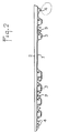
- la figure 1 est une perspective vue de dessous montrant une première forme'de réalisation de la semelle conforme à l'invention,
- la figure 2 est une élévation prise dans le plan II-II de la figure 1,
- la figure 3 est une coupe longitudinale prise suivant le plan III-III de la figure 1,
- la figure 4 est une coupe transversale prise suivant le plan IV-IV de la figure 1,
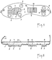
- la figure 5 est une vue de dessous illustrant une deuxième forme de réalisation de la semelle conforme à l'invention,
- la figure 6 est une coupe longitudinale prise suivant la ligne VI-VI de la figure 5,
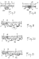
- les figures 7 et 8 sont des coupes représentant des variantes de réalisation du détail désigné sur la figure 4 par la flèche F.
- les figures 9 et 10 sont des coupes représentant également des variantes de réalisation d'un autre détail désigné sur la figure 3 par la flèche G.
- FIG. 1 is a perspective view from below showing a first embodiment of the sole according to the invention,
- FIG. 2 is an elevation taken in plane II-II of FIG. 1,
- FIG. 3 is a longitudinal section taken along the plane III-III of FIG. 1,
- FIG. 4 is a cross section taken along the plane IV-IV of FIG. 1,
- FIG. 5 is a bottom view illustrating a second embodiment of the sole according to the invention,
- FIG. 6 is a longitudinal section taken on the line VI-VI of FIG. 5,
- Figures 7 and 8 are sections showing alternative embodiments of the detail designated in Figure 4 by the arrow F.
- Figures 9 and 10 are sections also showing alternative embodiments of another detail designated in Figure 3 by the arrow G.
Quelle que soit la forme de réalisation choisie, la semelle comporte :
- une couche inférieure 1 en matériau dense, ferme et compact, résistant à l'abrasion, à la rupture et au cisaillement.
- et une couche supérieure 2 en matériau expansé léger et souple.
- a
lower layer 1 of dense, firm and compact material, resistant to abrasion, breakage and shear. - and an
upper layer 2 of light and flexible expanded material.
Avantageusement, la couche 1 est en caout-chouc et la couche 2 en mousse de polyuréthane, matériaux qui sont compatibles entre eux.Advantageously,
La couche inférieure 1 présente en saillie vers le bas des protubérances fermes 3 qui, dans l'exemple représenté sur les figures 1 et 5 sont des crampons étant donné que la chaussure est destinée à la pratique du football. Bien entendu, la forme de ces protubérances 3 généralement coniques dépend du sport pratiqué.The
Suivant la première forme de réalisation illustrée parles figures 1 à 4, les protubérances fermes 3 sont réparties à la périphérie de l'avant-pied et du talon ; outre les crampons, elles peuvent également comporter des barrettes avant et arrière 4 ayant des flancs inclinés vers l'arrière et une hauteur inférieure à celle desdits crampons.According to the first embodiment illustrated by FIGS. 1 to 4, the
De toute façon, la couche inférieure 1 délimite dans la zone médiane longitudinale entre les protubérances fermes antérieures, un ajourage d'avant-pied 5 et entre les protubérances postérieures, un ajourage de talon 6.In any case, the
La couche supérieure 2 recouvre la couche inférieure 1 et remplit les ajourages 5 et 6 en formant des patins 7 et 8 dont le dessous est situé sensiblement en prolongement du dessous de la couche inférieure 1.The
Ces patins de la couche supérieure 2 présentent en saillie vers le bas des protubérances souples 9 qui, dans l'exemple représenté sur les figures 1 et 5, sont des dents inclinées vers l'arrière (figures 3 et 6).These pads of the
L'injection et l'expansion de la couche supérieure 2 peuvent être effectuées dans un moule, non représenté, de façon à ce que cette couche assure la liaison, d'une part, avec la couche inférieure 1 en prenant forme dans les ajourages 5,6 et, d'autre part, avec une première de montage 10 à laquelle est fixée une tige 11. L'exécution de cette opération nécessite évidemment que la couche inférieure 1 ait été fabriquée auparavant, par vulcanisation par exemple, et soit déposée dans le dessous du moule d'injection avant que les côtés de ce moule soient refermés sur la forme dudit moule coiffée par la tige 11 montée sur la première 10.The injection and expansion of the
Dans la forme de réalisation illustrée par la figure 3, la première 10 comporte deux feuilles en matériau fibreux 12, 13 entre lesquelles est injecté un coin 14 en polyoléfine s'étendant de l'arrière du talon jusqu'à l'avant-pied. Cette première composite assimilable dans la zone médiane à un cambrion est préparée avant le montage de la tige 11 et permet de mieux répartir l'impact du talon du pied sur le semelage.In the embodiment illustrated in Figure 3, the first 10 comprises two sheets of
Bien entendu la première 10 peut être simple et limitée à la feuille 12; dans ce cas, la couche supérieure 2 est plus épaisse et s'étend jusqu 'à ladite feuille 12.Of course the first 10 can be simple and limited to the
La couche supérieure 2 adhère fortement à la couche inférieure 1 et épouse son relief dû aux surépaisseurs nécessaires pour assurer l'ancrage des protubérances fermes 3, la liaison du bord des ajourages 5,6 avec la couche supérieure 2...The
Celle-ci épouse donc le relief de la couche inférieure 1 en compensant les différences de hauteur de celui-ci par une épaisseur suffisante de ladite couche 2 au-dessus des parties les plus saillantes. Bien entendu, cette épaisseur est déterminée par le fait que le pied ne doit pas sentir les zones dures que constituent inévitablement les crampons 3, les barrettes 4 et les bordures 15 définies ci-après.It therefore follows the relief of the
Lors de l'expansion du matériau de la couche supérieure 2 dans le moule fermé, il est important qu'à la frontière des ajourages 5,6 de la couche inférieure 1, ce matériau expansé ne "bave" pas sur le matériau dense de la couche 1. A cet effet, cette couche inférieure 1 présente en saillie sur sa surface de dessus deux bordures profilées en U 15 dont l'aile libre délimite les ajourages 5 et 6 correspondants. Les ailes de chaque profilé délimitent une saignée 16 dans laquelle pénètre une nervure du dessous du moule ; cet ensemble : nervure-profilé constitue un joint qui, lorsque la couche inférieure 1 est positionnée dans le dessous du moule, empêche le matériau expansé formant le patin 7 ou 8 correspondant de baver ; en fait, ce matériau forme un rebord 17 qui recouvre l'aile libre du profilé 15 et la saignée 16 définit la limite du patin.During the expansion of the material of the
Suivant la deuxième forme de réalisation schématisée sur les figures 5 et 6, la couche inférieure 1 délimite, outre les ajourages 5 et 6, un troisième ajourage 18 situé dans la zone d'appui de la voûte plantaire; dès lors, la couche supérieure 2 comporte un troisième coussin 19 muni de protubérances souples 9.According to the second embodiment shown diagrammatically in FIGS. 5 and 6, the
Par ailleurs, la couche supérieure 2 est plus épaisse dès lors que la première de montage 20 est simple, au lieu d'être composite comme en 10 dans la première forme de réalisation.Furthermore, the
Bien entendu et ainsi que cela ressort de la figure 6, cette épaisseur croit vers le talon. Il en est de même pour la réalisation de la figure 3, si l'on considère que la couche 2 et le coin 14 forment un ensemble possédant sa souplesse propre.Of course and as shown in Figure 6, this thickness increases towards the heel. It is the same for the embodiment of Figure 3, if we consider that the
La surface de dessus de la couche supérieure 2 au contact de la première 10 ou 20 est unie et adhère à la surface de dessous de ladite première.The top surface of the
Quelle que soit la forme de réalisation choisie, les protubérances fermes 3 venues avec la couche inférieure 1 peuvent être :
- un crampon creux (figure 4) qui délimite, dans une collerette 21 faisant saillie dans le dessus de la couche 1 pour l'ancrage dudit crampon, une cuvette d'allégement 22, laquelle est remplie par le matériau expansé de la couche supérieure 2.
- un crampon enrobant une tête de renfort 23 (figure 7) et présentant aussi une collerette d'ancrage 21 avec
cuvette d'allègement 22. - un bossage 24 (figure 8) faisant saillie en-es-sous et au-dessus, ce bossage enrobant un insert métallique taraudé 25 pour le vissage d'une pointe ou d'un crampon démontable et interchangeable 26.
- ou autre
- a hollow spike (FIG. 4) which delimits, in a
flange 21 projecting into the top of thelayer 1 for anchoring said spike, a lighteningbowl 22, which is filled with the expanded material of theupper layer 2. - a crampon encasing a reinforcement head 23 (FIG. 7) and also having an anchoring
flange 21 with lighteningbowl 22. - a boss 24 (FIG. 8) projecting below and above, this boss coating a threaded
metal insert 25 for screwing a removable or interchangeable point orcrampon 26. - Or other
Quelle que soit la forme de réalisation choisie, les protubérances souples 9 venues avec les patins 7 et 8 de la couche supérieure 2 peuvent être :
- des dents (figure 3) inclinées vers l'arrière,
- des replis dentelés (figure 6) également inclinés vers l'arrière,
- des mini-crampons 9a (figure 9) en forme de bosses,
- des anneaux fendus 9b (figure 10),
- des barrettes
ou plis longitudinaux 9c entre lesquels s'étendent des dents transversales 9.
- teeth (Figure 3) inclined backwards,
- serrated folds (Figure 6) also inclined backwards,
- mini-studs 9a (FIG. 9) in the form of bumps,
- split rings 9b (FIG. 10),
- longitudinal bars or folds 9c between which extend
transverse teeth 9.
Par ailleurs, la figure 6 montre que les protubérances souples 9 ont sensiblement la même hauteur que les protubérances fermes 3 et la figure 3 que la hauteur des protubérances souples 9 peut être différente (plus petite sur le dessin) suivant l'effet recherché et la souplesse conférée à la couche supérieure 2.Furthermore, FIG. 6 shows that the
Une chaussure équipée d'un tel semelage réagit ainsi selon les terrains :
- sur terrain très mou, les protubérances fermes 3 pénètrent sans effort et les protubérances souples 9 également, de sorte que la fonction d'appui de ces dernières est moins importante que le supplément d'ancrage apporté par leur dessin agressif et leur forme anti-dérapante,
- sur terrain souple, idéal pour l'activité sportive, il y a complémentarité parfaite et équilibrée entre l'ancrage et l'appui, toutes les fonctions et possibilités du semelage étant sollicitées,
- sur terrain dur et sec, la fonction d'appui des protubérances souples 9 devient prépondérante, avec absorption des chocs et restitution d'énergie maximale ; l'appui des protubérances souples 9 limite également la déformation transversale de la semelle par creusement de sa partie centrale, suspendue entre des protubérances fermes 3 périphériques qui ne peuvent pénétrer dans le sol trop dur.
- on very soft ground, the
firm protrusions 3 penetrate effortlessly and theflexible protrusions 9 also, so that the support function of the latter is less important than the additional anchoring provided by their aggressive design and their non-slip shape , - on soft ground, ideal for sporting activity, there is perfect and balanced complementarity between anchoring and support, all the functions and possibilities of sole assembly being used,
- on hard and dry ground, the support function of the
flexible protrusions 9 becomes preponderant, with shock absorption and maximum energy restitution; the support of theflexible protrusions 9 also limits the transverse deformation of the sole by digging its central part, suspended betweenfirm protrusions 3 peripherals which cannot penetrate into the ground too hard.
Le semelage selon l'invention résout les problèmes posés par l'exercice des activités sportives sur terrain variés : légèreté, élasticité, ancrage, absorption de chocs et restitution d'énergie.The sole assembly according to the invention solves the problems posed by the exercise of sports activities on various terrains: lightness, elasticity, anchoring, shock absorption and energy restitution.
Ainsi que cela est indiqué dans ce qui précède, la fabrication de la chaussure peut avantageusement être effectuée par moulage préalable de la couche inférieure du semelage incluant selon les choix tous inserts, métalliques ou autres.As noted in the above, the manufacture of the shoe can advantageously be carried out by prior molding of the bottom layer of the sole assembly including, as desired, all inserts, metallic or other.
La fabrication peut également être exécutée en une seule opération, par deux injections simultanées sur une machine à deux têtes d'injection.Manufacturing can also be carried out in a single operation, by two simultaneous injections on a machine with two injection heads.
En variant les couleurs des matériaux, il est possible d'obtenir des semelles bicolores, en-dessous et sur les côtés. Par ailleurs, en augmentant ou en diminuant la densité du matériau expansé, il est possible d'obtenir avec le même moule des articles plus spécialement destinés à des contrées sèches ou humides.By varying the colors of the materials, it is possible to obtain two-tone soles, below and on the sides. Furthermore, by increasing or decreasing the density of the expanded material, it is possible to obtain with the same mold articles more especially intended for dry or wet regions.
Claims (9)
- Shoe sole for sporting and outdoor activities, comprising, on the one hand, a bottom layer (1) of dense, rigid and compact material, such as rubber, having rigid protuberances (3) distributed along the periphery and cut-outs (5, 6) situated in the bearing zones, in particular the zones of the metatarsus and the heel, in the longitudinal median zone between said rigid protuberances, and on the other hand, a lightweight top layer (2) of expanded material, such as polyurethane foam, ensuring the connection between the bottom layer and the midsole (10, 20) and the upper (11) of a shoe, and filling the cut-outs (5, 6) of the bottom layer (1) by forming pads (7, 8), the rigid protuberances being selected from a group comprising the studs (3) and the bosses (24),
characterized in that the rigid protuberances are intended for ensuring an effective grip on the ground and are selected from the group comprising, in addition to the aforesaid studs and bosses, the cleats (4) and the spikes (26),
in that the pads (7, 8) the bottom of which extends substantially as a continuation of the bottom of the bottom layer, have projecting flexible protuberances selected from the group comprising teeth (9) inclined towards the rear, toothed folds, mini spikes (9a), split rings (9b) and longitudinal cleats (9c). - Sole according to claim 1, characterized in that the top layer also has a pad (19) having flexible protuberances (9) in the bearing zone of the plantar arch.
- Sole according to claim 1 or 2, characterized in that in order to ensure the connection between the two layers (1, 2) at the boundary of the flash-free cut-outs (5, 6) on the bottom surface, the bottom layer (1) has a U-shaped skirt (15) projecting from its top surface and delimiting a groove (16) for marking the limit of the two layers, the pads (7, 8) of the top layer (2) having shoulders (17) adapted to cover the free flange of the aforesaid shaped skirt in order to delimit together with the latter the said groove (16) into which a rib of the mold penetrates, preventing the expanded material of the top layer (2) from escaping.
- Sole according to any one of claims 1 to 3, characterized in that the top layer (2) of expanded material has a thickness which increases in the direction of the heel.
- Sole according to claim 4, characterized in that the midsole (10) contains a distributing wedge (14), advantageously of polyolefins.
- Sole according to any one of claims 1 to 5, characterized in that the top layer (2) of expanded material molds and compensates for the differences in relief marking the top surface of the bottom layer.
- Sole according to any one of claims 1 to 6, characterized in that when they do not have metallic inserts or the like, the rigid protuberances (3) have a basin-shaped relief (22) filled with expanded material of the top layer (2).
- Sole according to any one of claims 1 to 7, characterized in that the flexible protuberances (9) have substantially the same height as the rigid protuberances (3).
- Sole according to any one of claims 1 to 8, characterized in that the flexible protuberances (9) have a different height from that of the rigid protuberances (3).
Priority Applications (1)
| Application Number | Priority Date | Filing Date | Title |
|---|---|---|---|
| AT89400805T ATE79228T1 (en) | 1988-03-22 | 1989-03-22 | SHOE SOLE FOR SPORTING ACTIVITIES, EVEN OUTDOORS. |
Applications Claiming Priority (2)
| Application Number | Priority Date | Filing Date | Title |
|---|---|---|---|
| FR8804054A FR2632497A1 (en) | 1988-03-22 | 1988-03-22 | SOLE OF SHOES FOR THE PRACTICE OF SPORTS AND SIMILAR ACTIVITIES |
| FR8804054 | 1988-03-22 |
Publications (3)
| Publication Number | Publication Date |
|---|---|
| EP0340053A1 EP0340053A1 (en) | 1989-11-02 |
| EP0340053B1 EP0340053B1 (en) | 1992-08-12 |
| EP0340053B2 true EP0340053B2 (en) | 1997-09-17 |
Family
ID=9364705
Family Applications (2)
| Application Number | Title | Priority Date | Filing Date |
|---|---|---|---|
| EP19890460006 Withdrawn EP0334781A1 (en) | 1988-03-22 | 1989-02-21 | Shoe sole for sporting and similar activities |
| EP89400805A Expired - Lifetime EP0340053B2 (en) | 1988-03-22 | 1989-03-22 | Shoe sole for sporting and outdoor activities |
Family Applications Before (1)
| Application Number | Title | Priority Date | Filing Date |
|---|---|---|---|
| EP19890460006 Withdrawn EP0334781A1 (en) | 1988-03-22 | 1989-02-21 | Shoe sole for sporting and similar activities |
Country Status (10)
| Country | Link |
|---|---|
| US (1) | US5077916A (en) |
| EP (2) | EP0334781A1 (en) |
| JP (1) | JPH0698052B2 (en) |
| KR (1) | KR900700028A (en) |
| AT (1) | ATE79228T1 (en) |
| BR (1) | BR8906474A (en) |
| DE (1) | DE68902415T3 (en) |
| ES (1) | ES2034665T3 (en) |
| FR (1) | FR2632497A1 (en) |
| WO (1) | WO1989008996A1 (en) |
Cited By (7)
| Publication number | Priority date | Publication date | Assignee | Title |
|---|---|---|---|---|
| US8966787B2 (en) | 2011-09-16 | 2015-03-03 | Nike, Inc. | Orientations for footwear ground-engaging member support features |
| US9032645B2 (en) | 2012-07-30 | 2015-05-19 | Nike, Inc. | Support features for footwear ground engaging members |
| US9138027B2 (en) | 2011-09-16 | 2015-09-22 | Nike, Inc. | Spacing for footwear ground-engaging member support features |
| US9210967B2 (en) | 2010-08-13 | 2015-12-15 | Nike, Inc. | Sole structure with traction elements |
| US9220320B2 (en) | 2011-09-16 | 2015-12-29 | Nike, Inc. | Sole arrangement with ground-engaging member support features |
| US9351537B2 (en) | 2009-10-01 | 2016-05-31 | Nike, Inc. | Rigid cantilevered stud |
| US9462845B2 (en) | 2011-01-19 | 2016-10-11 | Nike, Inc. | Composite sole structure |
Families Citing this family (129)
| Publication number | Priority date | Publication date | Assignee | Title |
|---|---|---|---|---|
| DK157387C (en) * | 1987-12-08 | 1990-06-05 | Eccolet Sko As | shoe sole |
| US6708424B1 (en) | 1988-07-15 | 2004-03-23 | Anatomic Research, Inc. | Shoe with naturally contoured sole |
| US6675498B1 (en) | 1988-07-15 | 2004-01-13 | Anatomic Research, Inc. | Shoe sole structures |
| US6810606B1 (en) * | 1988-07-15 | 2004-11-02 | Anatomic Research, Inc. | Shoe sole structures incorporating a contoured side |
| US5317819A (en) * | 1988-09-02 | 1994-06-07 | Ellis Iii Frampton E | Shoe with naturally contoured sole |
| US6314662B1 (en) | 1988-09-02 | 2001-11-13 | Anatomic Research, Inc. | Shoe sole with rounded inner and outer side surfaces |
| US6668470B2 (en) | 1988-09-02 | 2003-12-30 | Anatomic Research, Inc. | Shoe sole with rounded inner and outer side surfaces |
| US6662470B2 (en) | 1989-08-30 | 2003-12-16 | Anatomic Research, Inc. | Shoes sole structures |
| US6163982A (en) | 1989-08-30 | 2000-12-26 | Anatomic Research, Inc. | Shoe sole structures |
| US6789331B1 (en) | 1989-10-03 | 2004-09-14 | Anatomic Research, Inc. | Shoes sole structures |
| EP1004252B1 (en) * | 1989-10-03 | 2002-03-06 | Anatomic Research, Inc. | Shoe sole with a midsole having firmness and density variations |
| DE69133171T2 (en) * | 1990-01-10 | 2003-11-13 | Anatomic Res Inc | Construction of a shoe sole with extensive edges |
| US5992053A (en) * | 1990-11-21 | 1999-11-30 | Hansen; Ross | Detachable, cleated outer sole |
| US5335429A (en) * | 1990-11-21 | 1994-08-09 | Ross Hansen | Cleated outer sole |
| FR2681515B1 (en) * | 1991-09-19 | 1993-12-24 | Patrick Int | PROTUBERANCE SOLE FOR SPORT SHOES. |
| US7546699B2 (en) * | 1992-08-10 | 2009-06-16 | Anatomic Research, Inc. | Shoe sole structures |
| US5603170A (en) * | 1992-09-03 | 1997-02-18 | Hiro International Co., Ltd. | Fiber reinforced resin lift for shoes |
| US5325611A (en) * | 1992-10-19 | 1994-07-05 | Brown Group, Inc. | Comfort cradle system for footwear construction |
| WO1994013164A1 (en) * | 1992-12-10 | 1994-06-23 | Nike International Ltd. | Bonding of rubber to plastic in footwear |
| US5367791A (en) * | 1993-02-04 | 1994-11-29 | Asahi, Inc. | Shoe sole |
| US5377431A (en) * | 1993-06-15 | 1995-01-03 | Walker; Andrew S. | Directionally yieldable cleat assembly |
| US5465507A (en) * | 1994-04-13 | 1995-11-14 | Osage Footwear, Inc. | Integral sole with footprint embossing |
| NL9500145A (en) * | 1995-01-26 | 1996-09-02 | Carolus Joannes Maria Pijnenbu | Football shoe sole, method of manufacturing a football shoe sole and football shoe thus obtained. |
| US5761833A (en) * | 1995-12-22 | 1998-06-09 | Softspikes, Inc. | Athletic shoe traction system for use on turf |
| US5832636A (en) * | 1996-09-06 | 1998-11-10 | Nike, Inc. | Article of footwear having non-clogging sole |
| US7634529B2 (en) | 1996-11-29 | 2009-12-15 | Ellis Iii Frampton E | Personal and server computers having microchips with multiple processing units and internal firewalls |
| CA2210771C (en) * | 1996-12-20 | 2000-12-05 | Softspikes, Inc. | Golf cleat |
| US5799417A (en) * | 1997-01-13 | 1998-09-01 | Bata Limited | Shoe sole with removal insert |
| US5926974A (en) * | 1997-01-17 | 1999-07-27 | Nike, Inc. | Footwear with mountain goat traction elements |
| US5862614A (en) * | 1997-01-31 | 1999-01-26 | Nine West Group, Inc. | Indoor exercise shoe and sole therefor |
| US6131314A (en) * | 1997-12-08 | 2000-10-17 | Professional Kicking Services, Inc. | Plant shoe for placekickers and method of use thereof |
| US6023860A (en) * | 1997-12-11 | 2000-02-15 | Softspikes, Inc. | Athletic shoe cleat |
| US5979083A (en) * | 1998-01-23 | 1999-11-09 | Acushnet Company | Multi-layer outsole |
| US6948264B1 (en) | 2000-04-26 | 2005-09-27 | Lyden Robert M | Non-clogging sole for article of footwear |
| GB0027750D0 (en) * | 2000-11-14 | 2000-12-27 | Trisport Ltd | Studded footwear |
| DE60110053T2 (en) * | 2001-06-11 | 2005-09-08 | Calzaturificio S.C.A.R.P.A. S.P.A., Asolo | Sole for sports shoe |
| JP2003033201A (en) * | 2001-07-25 | 2003-02-04 | Sumitomo Rubber Ind Ltd | Outsole and method for making the same |
| US6759443B2 (en) | 2001-12-21 | 2004-07-06 | Basf Corporation | Polyurethane foam composition and additive useful in shoe sole applications and methods of making same |
| ITPD20020153A1 (en) * | 2002-06-06 | 2003-12-09 | Geox Spa | FOOTWEAR STRUCTURE WITH PERMEABLE AND BREATHABLE UPPER WHICH COATS AT LEAST PARTIALLY THE WATERPROOF SOLE MADE BREATHABLE. |
| US6834445B2 (en) | 2002-07-16 | 2004-12-28 | Softspikes, Llc | Shoe cleat with improved traction |
| US6834446B2 (en) | 2002-08-27 | 2004-12-28 | Softspikes, Llc | Indexable shoe cleat with improved traction |
| WO2004032660A1 (en) * | 2002-10-10 | 2004-04-22 | Sumitomo Rubber Industries, Ltd. | Tennis shoes |
| CN100411556C (en) * | 2002-10-10 | 2008-08-20 | 住胶体育用品株式会社 | Tennis shoes |
| US6904707B2 (en) | 2003-07-01 | 2005-06-14 | Softspikes, Llc | Indexable shoe cleat with improved traction |
| WO2005018361A2 (en) | 2003-08-11 | 2005-03-03 | Softspikes, Llc | Shoe cleat |
| US7047672B2 (en) * | 2003-10-17 | 2006-05-23 | Nike, Inc. | Sole for article of footwear for sand surfaces |
| US20050115107A1 (en) * | 2003-12-01 | 2005-06-02 | Schumacher James H. | Flexible outsole |
| EP1591031A1 (en) * | 2004-04-26 | 2005-11-02 | Cheng-Hsian Chi | Method for making a shoe |
| US7204044B2 (en) * | 2004-04-06 | 2007-04-17 | Nike, Inc. | Sole for article of footwear for granular surfaces |
| US8291618B2 (en) | 2004-11-22 | 2012-10-23 | Frampton E. Ellis | Devices with internal flexibility sipes, including siped chambers for footwear |
| CA2630817C (en) | 2004-11-22 | 2016-10-18 | Frampton E. Ellis | Devices with internal flexibility sipes, including siped chambers for footwear |
| US8256147B2 (en) | 2004-11-22 | 2012-09-04 | Frampton E. Eliis | Devices with internal flexibility sipes, including siped chambers for footwear |
| US7549236B2 (en) * | 2006-03-09 | 2009-06-23 | New England Footwear, Llc | Footwear with independent suspension and protection |
| US7644521B2 (en) * | 2006-04-03 | 2010-01-12 | Ariat International, Inc. | Footwear with rest support |
| US7793428B2 (en) * | 2007-03-07 | 2010-09-14 | Nike, Inc. | Footwear with removable midsole having projections |
| US7827705B2 (en) | 2007-03-08 | 2010-11-09 | Nike, Inc. | Article of footwear with multiple cleat sizes |
| US7802379B2 (en) * | 2007-03-08 | 2010-09-28 | Nike, Inc. | Article of footwear with indented tip cleats |
| US7966748B2 (en) * | 2007-04-16 | 2011-06-28 | Earl J. & Kimberly Votolato, Trustees Of The Votolato Living Trust | Elastic overshoe with sandwiched sole pads |
| US7882648B2 (en) * | 2007-06-21 | 2011-02-08 | Nike, Inc. | Footwear with laminated sole assembly |
| US8125796B2 (en) | 2007-11-21 | 2012-02-28 | Frampton E. Ellis | Devices with faraday cages and internal flexibility sipes |
| US8631590B2 (en) * | 2008-06-04 | 2014-01-21 | Nike, Inc. | Article of footwear for soccer |
| US9003679B2 (en) * | 2008-08-06 | 2015-04-14 | Nike, Inc. | Customization of inner sole board |
| US20100050475A1 (en) * | 2008-08-26 | 2010-03-04 | Benz Erek T | Footwear sole structure |
| JP2011115276A (en) * | 2009-12-01 | 2011-06-16 | Creative Workshop (Internatl) Co Ltd | Combined shoe |
| US8677655B2 (en) * | 2010-01-19 | 2014-03-25 | Ming Te Chen | Shoe with anti-slip device |
| FR2955466B1 (en) * | 2010-01-25 | 2012-04-20 | Salomon Sas | IMPROVED SHOE SHOE |
| US8322049B2 (en) | 2010-07-30 | 2012-12-04 | Nike, Inc. | Wear-resistant outsole |
| US8529267B2 (en) | 2010-11-01 | 2013-09-10 | Nike, Inc. | Integrated training system for articles of footwear |
| AT510266B1 (en) * | 2010-11-16 | 2012-03-15 | Atomic Austria Gmbh | METHOD FOR PRODUCING A SHELL PART OF A SPORTS SHOE AND A SHELL THAT MADE ACCORDING TO THIS METHOD AND A SPORTS SHOE EQUIPPED WITH THIS SHOE PART |
| US8707587B2 (en) * | 2010-12-29 | 2014-04-29 | Reebok International Limited | Sole and article of footwear |
| US8931187B2 (en) | 2011-08-25 | 2015-01-13 | Tbl Licensing Llc | Wave technology |
| US8806779B2 (en) | 2011-09-16 | 2014-08-19 | Nike, Inc. | Shaped support features for footwear ground-engaging members |
| EP2969058B1 (en) | 2013-03-14 | 2020-05-13 | Icon Health & Fitness, Inc. | Strength training apparatus with flywheel and related methods |
| USD732810S1 (en) | 2013-08-08 | 2015-06-30 | Tbl Licensing Llc | Footwear outsole |
| JP6055554B2 (en) * | 2013-10-10 | 2016-12-27 | 株式会社アシックス | Shoe sole |
| EP3974036A1 (en) | 2013-12-26 | 2022-03-30 | iFIT Inc. | Magnetic resistance mechanism in a cable machine |
| US9516918B2 (en) | 2014-01-16 | 2016-12-13 | Nike, Inc. | Sole system having movable protruding members |
| US9516917B2 (en) * | 2014-01-16 | 2016-12-13 | Nike, Inc. | Sole system having protruding members |
| WO2015138339A1 (en) | 2014-03-10 | 2015-09-17 | Icon Health & Fitness, Inc. | Pressure sensor to quantify work |
| CN104970487A (en) * | 2014-04-10 | 2015-10-14 | 海·克雷默 | Buffering shoe sole |
| WO2015191445A1 (en) | 2014-06-09 | 2015-12-17 | Icon Health & Fitness, Inc. | Cable system incorporated into a treadmill |
| US9538813B1 (en) | 2014-08-20 | 2017-01-10 | Akervall Technologies, Inc. | Energy absorbing elements for footwear and method of use |
| US9918512B2 (en) * | 2014-09-08 | 2018-03-20 | Sequence Llc | Footwear with support and traction |
| WO2016059581A1 (en) * | 2014-10-15 | 2016-04-21 | Back2Backcountry S.N.C. Di Marco Locatelli E Robert Behrens | Snowshoe |
| WO2016077443A1 (en) * | 2014-11-12 | 2016-05-19 | Nike Innovate C.V. | Article including an outer layer with areas of varying hardnesses |
| US10568383B2 (en) | 2015-01-16 | 2020-02-25 | Nike, Inc. | Sole system for an article of footwear incorporating a knitted component with a one-piece knit outsole and a tensile element |
| US9775401B2 (en) | 2015-01-16 | 2017-10-03 | Nike, Inc. | Sole system for an article of footwear incorporating a knitted component with a one-piece knit outsole |
| US9848673B2 (en) * | 2015-01-16 | 2017-12-26 | Nike, Inc. | Vacuum formed knit sole system for an article of footwear incorporating a knitted component |
| US10258828B2 (en) | 2015-01-16 | 2019-04-16 | Icon Health & Fitness, Inc. | Controls for an exercise device |
| US9820530B2 (en) | 2015-01-16 | 2017-11-21 | Nike, Inc. | Knit article of footwear with customized midsole and customized cleat arrangement |
| DE102015202169A1 (en) | 2015-02-06 | 2016-08-11 | Adidas Ag | Sole for a shoe |
| US10953305B2 (en) | 2015-08-26 | 2021-03-23 | Icon Health & Fitness, Inc. | Strength exercise mechanisms |
| US9648925B2 (en) * | 2015-09-23 | 2017-05-16 | Hyman Kramer | Footwear devices |
| WO2017115417A1 (en) * | 2015-12-28 | 2017-07-06 | 株式会社アシックス | Shoe member, shoe, and method for manufacturing same |
| US10856610B2 (en) | 2016-01-15 | 2020-12-08 | Hoe-Phuan Ng | Manual and dynamic shoe comfortness adjustment methods |
| US10980313B2 (en) * | 2016-03-04 | 2021-04-20 | Nike, Inc. | Article of footwear and sole structure with a central forefoot ridge element |
| US10016014B2 (en) * | 2016-03-04 | 2018-07-10 | Nike, Inc. | Article of footwear and sole structure with sensory node elements disposed along sole perimeter |
| US10493349B2 (en) | 2016-03-18 | 2019-12-03 | Icon Health & Fitness, Inc. | Display on exercise device |
| US10272317B2 (en) | 2016-03-18 | 2019-04-30 | Icon Health & Fitness, Inc. | Lighted pace feature in a treadmill |
| US10561894B2 (en) | 2016-03-18 | 2020-02-18 | Icon Health & Fitness, Inc. | Treadmill with removable supports |
| US10625137B2 (en) | 2016-03-18 | 2020-04-21 | Icon Health & Fitness, Inc. | Coordinated displays in an exercise device |
| US10293211B2 (en) | 2016-03-18 | 2019-05-21 | Icon Health & Fitness, Inc. | Coordinated weight selection |
| US10252109B2 (en) | 2016-05-13 | 2019-04-09 | Icon Health & Fitness, Inc. | Weight platform treadmill |
| US10441844B2 (en) | 2016-07-01 | 2019-10-15 | Icon Health & Fitness, Inc. | Cooling systems and methods for exercise equipment |
| US10471299B2 (en) | 2016-07-01 | 2019-11-12 | Icon Health & Fitness, Inc. | Systems and methods for cooling internal exercise equipment components |
| US10477916B2 (en) * | 2016-10-10 | 2019-11-19 | Nike, Inc. | Sole structure for an article of footwear with first and second midsole bodies |
| US10500473B2 (en) | 2016-10-10 | 2019-12-10 | Icon Health & Fitness, Inc. | Console positioning |
| US10376736B2 (en) | 2016-10-12 | 2019-08-13 | Icon Health & Fitness, Inc. | Cooling an exercise device during a dive motor runway condition |
| US10661114B2 (en) | 2016-11-01 | 2020-05-26 | Icon Health & Fitness, Inc. | Body weight lift mechanism on treadmill |
| TWI646997B (en) | 2016-11-01 | 2019-01-11 | 美商愛康運動與健康公司 | Distance sensor for console positioning |
| TWI680782B (en) | 2016-12-05 | 2020-01-01 | 美商愛康運動與健康公司 | Offsetting treadmill deck weight during operation |
| TWI722450B (en) | 2017-08-16 | 2021-03-21 | 美商愛康運動與健康公司 | System for opposing axial impact loading in a motor |
| US10492565B2 (en) * | 2017-10-06 | 2019-12-03 | Wolverine Outdoors, Inc. | Footwear with improved traction |
| US10729965B2 (en) | 2017-12-22 | 2020-08-04 | Icon Health & Fitness, Inc. | Audible belt guide in a treadmill |
| US10492564B1 (en) * | 2018-05-14 | 2019-12-03 | Wolverine Outdoors, Inc. | Footwear construction |
| USD912954S1 (en) | 2018-08-01 | 2021-03-16 | Tbl Licensing Llc | Footwear |
| USD905408S1 (en) | 2018-08-01 | 2020-12-22 | Tbl Licensing Llc | Footwear outsole |
| USD905411S1 (en) | 2018-08-01 | 2020-12-22 | Tbl Licensing Llc | Footwear outsole |
| USD905406S1 (en) | 2018-08-01 | 2020-12-22 | Tbl Licensing Llc | Footwear outsole |
| TWI789574B (en) * | 2019-03-01 | 2023-01-11 | 荷蘭商耐克創新有限合夥公司 | Article of footwear with midfoot flexibility |
| US11627780B2 (en) * | 2019-05-31 | 2023-04-18 | Nike, Inc. | Sole structure for article of footwear |
| US11425958B2 (en) * | 2019-06-07 | 2022-08-30 | Acushnet Company | Golf shoe having midsole and outsole for providing flex and stability |
| US11425959B2 (en) * | 2019-06-07 | 2022-08-30 | Acushnet Company | Golf shoe having composite plate in midsole for providing flex and stabti jty |
| JP7104113B2 (en) * | 2019-08-26 | 2022-07-20 | アクシュネット カンパニー | Golf shoes with outsole with crossing track including traction member |
| US20210127785A1 (en) * | 2019-11-05 | 2021-05-06 | Nike, Inc. | Foot support components for articles of footwear including multiple flexible projections at the ground-facing surface |
| US11751629B1 (en) * | 2020-07-02 | 2023-09-12 | Stable Step LLC | Two-piece insole |
| CN112917963B (en) * | 2021-01-15 | 2023-02-14 | 黎明职业大学 | Machining device and technology for anti-skid sole |
| US20230270208A1 (en) * | 2022-02-28 | 2023-08-31 | Puma SE | Article of footwear having a sole plate with spikes |
| US11576466B1 (en) * | 2022-04-29 | 2023-02-14 | Adidas Ag | Outsole for a shoe |
Family Cites Families (8)
| Publication number | Priority date | Publication date | Assignee | Title |
|---|---|---|---|---|
| US1272098A (en) * | 1917-08-27 | 1918-07-09 | John P Reily | Boot or shoe heel. |
| US2930149A (en) * | 1959-01-28 | 1960-03-29 | Ripple Sole Corp | Resilient shoe sole and wedge construction |
| US3559308A (en) * | 1969-09-17 | 1971-02-02 | Wright & Co Inc E T | Cleated outsole |
| FR2374863A1 (en) * | 1976-07-29 | 1978-07-21 | Adidas Chaussures | SOLE FOR SPORTS AND LEISURE SHOES |
| DE3112390A1 (en) * | 1981-03-28 | 1982-10-07 | Werner 8520 Erlangen Frör | FASTENING OF A GRIP ELEMENT IN THE SOLE OF A SPORTSHOE |
| US4398357A (en) * | 1981-06-01 | 1983-08-16 | Stride Rite International, Ltd. | Outsole |
| US4667423A (en) * | 1985-05-28 | 1987-05-26 | Autry Industries, Inc. | Resilient composite midsole and method of making |
| US4897936A (en) * | 1988-02-16 | 1990-02-06 | Kaepa, Inc. | Shoe sole construction |
-
1988
- 1988-03-22 FR FR8804054A patent/FR2632497A1/en not_active Withdrawn
-
1989
- 1989-02-21 EP EP19890460006 patent/EP0334781A1/en not_active Withdrawn
- 1989-03-22 KR KR1019890702166A patent/KR900700028A/en not_active Application Discontinuation
- 1989-03-22 AT AT89400805T patent/ATE79228T1/en not_active IP Right Cessation
- 1989-03-22 BR BR898906474A patent/BR8906474A/en active Search and Examination
- 1989-03-22 WO PCT/FR1989/000132 patent/WO1989008996A1/en unknown
- 1989-03-22 DE DE68902415T patent/DE68902415T3/en not_active Expired - Fee Related
- 1989-03-22 EP EP89400805A patent/EP0340053B2/en not_active Expired - Lifetime
- 1989-03-22 ES ES198989400805T patent/ES2034665T3/en not_active Expired - Lifetime
- 1989-03-22 JP JP1504133A patent/JPH0698052B2/en not_active Expired - Lifetime
-
1991
- 1991-03-20 US US07/673,255 patent/US5077916A/en not_active Expired - Fee Related
Cited By (8)
| Publication number | Priority date | Publication date | Assignee | Title |
|---|---|---|---|---|
| US9351537B2 (en) | 2009-10-01 | 2016-05-31 | Nike, Inc. | Rigid cantilevered stud |
| US9210967B2 (en) | 2010-08-13 | 2015-12-15 | Nike, Inc. | Sole structure with traction elements |
| US9462845B2 (en) | 2011-01-19 | 2016-10-11 | Nike, Inc. | Composite sole structure |
| US9549589B2 (en) | 2011-01-19 | 2017-01-24 | Nike, Inc. | Composite sole structure |
| US8966787B2 (en) | 2011-09-16 | 2015-03-03 | Nike, Inc. | Orientations for footwear ground-engaging member support features |
| US9138027B2 (en) | 2011-09-16 | 2015-09-22 | Nike, Inc. | Spacing for footwear ground-engaging member support features |
| US9220320B2 (en) | 2011-09-16 | 2015-12-29 | Nike, Inc. | Sole arrangement with ground-engaging member support features |
| US9032645B2 (en) | 2012-07-30 | 2015-05-19 | Nike, Inc. | Support features for footwear ground engaging members |
Also Published As
| Publication number | Publication date |
|---|---|
| EP0340053B1 (en) | 1992-08-12 |
| DE68902415D1 (en) | 1992-09-17 |
| EP0340053A1 (en) | 1989-11-02 |
| KR900700028A (en) | 1990-08-11 |
| US5077916A (en) | 1992-01-07 |
| BR8906474A (en) | 1990-12-04 |
| ES2034665T3 (en) | 1993-04-01 |
| JPH02503527A (en) | 1990-10-25 |
| FR2632497A1 (en) | 1989-12-15 |
| DE68902415T2 (en) | 1993-03-04 |
| JPH0698052B2 (en) | 1994-12-07 |
| EP0334781A1 (en) | 1989-09-27 |
| DE68902415T3 (en) | 1998-04-09 |
| ATE79228T1 (en) | 1992-08-15 |
| WO1989008996A1 (en) | 1989-10-05 |
Similar Documents
| Publication | Publication Date | Title |
|---|---|---|
| EP0340053B2 (en) | Shoe sole for sporting and outdoor activities | |
| EP0548475B1 (en) | Multilayered athletic shoe sole | |
| EP0533570B1 (en) | Profiled sole for sport shoes | |
| EP0395538B1 (en) | Sole for a sports shoe | |
| US4194310A (en) | Athletic shoe for artificial turf with molded cleats on the sides thereof | |
| EP1247468A1 (en) | Walking shoe with removable upper reinforcement and reinforcement for such a shoe | |
| FR2475371A1 (en) | SOLE FOR SPORTSHOTS WITH OBLIQUE CRAMPONNAGE | |
| EP0146438A1 (en) | Modification of shoes with elastic soles, especially sports shoes | |
| EP1222868A1 (en) | Midsole and shoe provided with such a sole | |
| EP0383685A1 (en) | Hollow sole filled with resilient beads for shoes for massaging the feet | |
| EP3047747A1 (en) | Shoe with improved structure | |
| FR2483196A1 (en) | SHOE FOR GOLF PRACTICE | |
| FR2775875A1 (en) | Walking boot | |
| FR2631844A1 (en) | BACKGROUND SKI SHOE | |
| WO2007017594A1 (en) | Shoe fitting set consisting of a shoe and a range of interchangeable insoles provided with shock-absorbing protrusions | |
| EP2922436A1 (en) | Shoe sole | |
| EP0756832B1 (en) | Shoe for sliding sports | |
| EP0022716B1 (en) | Sole for athletic shoe | |
| EP3405061A1 (en) | Footwear sole | |
| EP4013259A1 (en) | Monolithic cycling shoe sole | |
| EP3000342B1 (en) | Inner boot with raised padding for sports footwear | |
| WO2020089735A1 (en) | Snowshoe with sole comprising crampon areas | |
| FR2652239A1 (en) | Inner sole (insole) for a shoe and shoe provided with such a sole | |
| FR3075058A1 (en) | SNOW RACKET WITH REINFORCING ELEMENT | |
| EP0774216A1 (en) | Improved footwear and method of making the same |
Legal Events
| Date | Code | Title | Description |
|---|---|---|---|
| PUAI | Public reference made under article 153(3) epc to a published international application that has entered the european phase |
Free format text: ORIGINAL CODE: 0009012 |
|
| AK | Designated contracting states |
Kind code of ref document: A1 Designated state(s): AT BE CH DE ES FR GB IT LI LU NL SE |
|
| 17P | Request for examination filed |
Effective date: 19900414 |
|
| 17Q | First examination report despatched |
Effective date: 19911022 |
|
| GRAA | (expected) grant |
Free format text: ORIGINAL CODE: 0009210 |
|
| AK | Designated contracting states |
Kind code of ref document: B1 Designated state(s): AT BE CH DE ES FR GB IT LI LU NL SE |
|
| REF | Corresponds to: |
Ref document number: 79228 Country of ref document: AT Date of ref document: 19920815 Kind code of ref document: T |
|
| REF | Corresponds to: |
Ref document number: 68902415 Country of ref document: DE Date of ref document: 19920917 |
|
| ITF | It: translation for a ep patent filed |
Owner name: JACOBACCI & PERANI S.P.A. |
|
| REG | Reference to a national code |
Ref country code: GB Ref legal event code: 732 |
|
| GBT | Gb: translation of ep patent filed (gb section 77(6)(a)/1977) | ||
| RAP2 | Party data changed (patent owner data changed or rights of a patent transferred) |
Owner name: PATRICK INTERNATIONAL |
|
| BECA | Be: change of holder's address |
Free format text: 920812 S.A. *PATRICK INTERNATIONAL:6 RUE FORTUNE PARENTEAU, 85700 POUZAUGES |
|
| BECH | Be: change of holder |
Free format text: 920812 S.A. *PATRICK INTERNATIONAL |
|
| REG | Reference to a national code |
Ref country code: CH Ref legal event code: PFA Free format text: PATRICK INTERNATIONAL |
|
| NLT2 | Nl: modifications (of names), taken from the european patent patent bulletin |
Owner name: PATRICK INTERNATIONAL TE POUZAUGES, FRANKRIJK. |
|
| PLBI | Opposition filed |
Free format text: ORIGINAL CODE: 0009260 |
|
| REG | Reference to a national code |
Ref country code: ES Ref legal event code: PC2A Owner name: PATRICK INTERNATIONAL SOCIETE ANONYME |
|
| 26 | Opposition filed |
Opponent name: PUMA AG RUDOLF DASSLER SPORT Effective date: 19930511 |
|
| NLR1 | Nl: opposition has been filed with the epo |
Opponent name: PUMA AG RUDOLF DASSLER SPORT |
|
| NLS | Nl: assignments of ep-patents |
Owner name: PATRICK INTERNATIONAL SOCIETE ANONYME TE POUZAUGES |
|
| PGFP | Annual fee paid to national office [announced via postgrant information from national office to epo] |
Ref country code: AT Payment date: 19940221 Year of fee payment: 6 |
|
| PGFP | Annual fee paid to national office [announced via postgrant information from national office to epo] |
Ref country code: CH Payment date: 19940316 Year of fee payment: 6 |
|
| PGFP | Annual fee paid to national office [announced via postgrant information from national office to epo] |
Ref country code: SE Payment date: 19940317 Year of fee payment: 6 |
|
| PGFP | Annual fee paid to national office [announced via postgrant information from national office to epo] |
Ref country code: NL Payment date: 19940331 Year of fee payment: 6 |
|
| PGFP | Annual fee paid to national office [announced via postgrant information from national office to epo] |
Ref country code: BE Payment date: 19940413 Year of fee payment: 6 |
|
| PGFP | Annual fee paid to national office [announced via postgrant information from national office to epo] |
Ref country code: LU Payment date: 19940430 Year of fee payment: 6 |
|
| EPTA | Lu: last paid annual fee | ||
| EAL | Se: european patent in force in sweden |
Ref document number: 89400805.1 |
|
| PG25 | Lapsed in a contracting state [announced via postgrant information from national office to epo] |
Ref country code: LU Free format text: LAPSE BECAUSE OF NON-PAYMENT OF DUE FEES Effective date: 19950322 Ref country code: AT Effective date: 19950322 |
|
| PG25 | Lapsed in a contracting state [announced via postgrant information from national office to epo] |
Ref country code: SE Effective date: 19950323 |
|
| PG25 | Lapsed in a contracting state [announced via postgrant information from national office to epo] |
Ref country code: LI Effective date: 19950331 Ref country code: CH Effective date: 19950331 Ref country code: BE Effective date: 19950331 |
|
| BERE | Be: lapsed |
Owner name: S.A. PATRICK INTERNATIONAL Effective date: 19950331 |
|
| PG25 | Lapsed in a contracting state [announced via postgrant information from national office to epo] |
Ref country code: NL Effective date: 19951001 |
|
| REG | Reference to a national code |
Ref country code: CH Ref legal event code: PL |
|
| NLV4 | Nl: lapsed or anulled due to non-payment of the annual fee |
Effective date: 19951001 |
|
| EUG | Se: european patent has lapsed |
Ref document number: 89400805.1 |
|
| PLAW | Interlocutory decision in opposition |
Free format text: ORIGINAL CODE: EPIDOS IDOP |
|
| PGFP | Annual fee paid to national office [announced via postgrant information from national office to epo] |
Ref country code: ES Payment date: 19970325 Year of fee payment: 9 |
|
| PLAW | Interlocutory decision in opposition |
Free format text: ORIGINAL CODE: EPIDOS IDOP |
|
| PUAH | Patent maintained in amended form |
Free format text: ORIGINAL CODE: 0009272 |
|
| STAA | Information on the status of an ep patent application or granted ep patent |
Free format text: STATUS: PATENT MAINTAINED AS AMENDED |
|
| 27A | Patent maintained in amended form |
Effective date: 19970917 |
|
| AK | Designated contracting states |
Kind code of ref document: B2 Designated state(s): AT BE CH DE ES FR GB IT LI LU NL SE |
|
| REG | Reference to a national code |
Ref country code: CH Ref legal event code: AEN Free format text: MAINTIEN DU BREVET DONT L'ETENDUE A ETE MODIFIEE |
|
| GBTA | Gb: translation of amended ep patent filed (gb section 77(6)(b)/1977) | ||
| PGFP | Annual fee paid to national office [announced via postgrant information from national office to epo] |
Ref country code: GB Payment date: 19980317 Year of fee payment: 10 |
|
| PGFP | Annual fee paid to national office [announced via postgrant information from national office to epo] |
Ref country code: DE Payment date: 19980319 Year of fee payment: 10 |
|
| PG25 | Lapsed in a contracting state [announced via postgrant information from national office to epo] |
Ref country code: ES Free format text: LAPSE BECAUSE OF NON-PAYMENT OF DUE FEES Effective date: 19980323 |
|
| PG25 | Lapsed in a contracting state [announced via postgrant information from national office to epo] |
Ref country code: GB Free format text: LAPSE BECAUSE OF NON-PAYMENT OF DUE FEES Effective date: 19990322 |
|
| GBPC | Gb: european patent ceased through non-payment of renewal fee |
Effective date: 19990322 |
|
| PG25 | Lapsed in a contracting state [announced via postgrant information from national office to epo] |
Ref country code: DE Free format text: LAPSE BECAUSE OF NON-PAYMENT OF DUE FEES Effective date: 20000101 |
|
| PGFP | Annual fee paid to national office [announced via postgrant information from national office to epo] |
Ref country code: FR Payment date: 20000315 Year of fee payment: 12 |
|
| REG | Reference to a national code |
Ref country code: ES Ref legal event code: FD2A Effective date: 20000503 |
|
| PG25 | Lapsed in a contracting state [announced via postgrant information from national office to epo] |
Ref country code: FR Free format text: LAPSE BECAUSE OF NON-PAYMENT OF DUE FEES Effective date: 20011130 |
|
| REG | Reference to a national code |
Ref country code: FR Ref legal event code: ST |
|
| PG25 | Lapsed in a contracting state [announced via postgrant information from national office to epo] |
Ref country code: IT Free format text: LAPSE BECAUSE OF NON-PAYMENT OF DUE FEES Effective date: 20050322 |