EP0340633A2 - Encoding and decoding method and apparatus - Google Patents
Encoding and decoding method and apparatus Download PDFInfo
- Publication number
- EP0340633A2 EP0340633A2 EP89107634A EP89107634A EP0340633A2 EP 0340633 A2 EP0340633 A2 EP 0340633A2 EP 89107634 A EP89107634 A EP 89107634A EP 89107634 A EP89107634 A EP 89107634A EP 0340633 A2 EP0340633 A2 EP 0340633A2
- Authority
- EP
- European Patent Office
- Prior art keywords
- code
- conversion
- result
- predetermined
- information
- Prior art date
- Legal status (The legal status is an assumption and is not a legal conclusion. Google has not performed a legal analysis and makes no representation as to the accuracy of the status listed.)
- Granted
Links
Images


Classifications
-
- H—ELECTRICITY
- H04—ELECTRIC COMMUNICATION TECHNIQUE
- H04L—TRANSMISSION OF DIGITAL INFORMATION, e.g. TELEGRAPHIC COMMUNICATION
- H04L9/00—Cryptographic mechanisms or cryptographic arrangements for secret or secure communications; Network security protocols
- H04L9/30—Public key, i.e. encryption algorithm being computationally infeasible to invert or user's encryption keys not requiring secrecy
- H04L9/3006—Public key, i.e. encryption algorithm being computationally infeasible to invert or user's encryption keys not requiring secrecy underlying computational problems or public-key parameters
- H04L9/302—Public key, i.e. encryption algorithm being computationally infeasible to invert or user's encryption keys not requiring secrecy underlying computational problems or public-key parameters involving the integer factorization problem, e.g. RSA or quadratic sieve [QS] schemes
Definitions
- the present invention relates to a method for encoding information into a code which cannot be deciphered by an eavesdropper and a method of decoding the code to recover the original information.
- Typical of encoding and decoding methods heretofore proposed is an RSA method which is disclosed by R.L. Rivest, A. Shamir and L. Addleman in a paper entitled "A Method for Obtaining Digital Signatures and Public-key Crypto-systems", Comm. ACM, Vol. 21, No. 2, pp. 120 - 126, 1978.
- the encoding and decoding methods will be limited to the RSA method by way of example. Let the manipulation for converting information into a cryptogram and the manipulation for decoding a cryptogram into original information be called encoding and decoding, respectively.
- the encoding and decoding procedures according to the RSA method use an encoding key e and a decoding key d each being represented by a numerical value, and a common key n shared by both of encoding and decoding also being represented by a numerical value.
- These numerical values e , d , and n are predetermined integers. How to select the numerical values e , d , and n is not directly relevant to the present invention and therefore will not be described herein.
- the coding procedure particular to the RSA method begins with a step of obtaining a numerical representation P of information.
- the RSA method as discussed in the previously mentioned paper, is elaborated not only to prevent an unauthorized person from eavesdropping information but also to eliminate occurrences that a person transmitted information later denies the transmission for fraud and that an unauthorized person transmits information pretending to be an authorized person.
- a problem with the prior art encoding and decoding methods discussed above is that the information P has to be smaller than the common key n . Otherwise the information rendered by a numerical representation P and the information rendered by a numerical representation P+n would become indistinguishable because a residual produced by the division by the common key n is computed during the course of encoding operation. Further, to conform to the binary notation adopted fcr communications and computers, input information is usually divided such that the information P to be encoded is one bit shorter than the common key n . Moreover, since information applicable to communications and computers is managed by being fractioned to a length of 2's power such as 1024 bits, even the increase in the bit length by one amounts to an increase by 1024 in total. Thus, the prior art encoding method critically degrades the transmission of information and the efficiency of storage.
- an encoding method for producing a code associated with inputted information comprises the steps of (a) if a numerical representation of the inputted information is smaller than a predetermined numerical value, applying a predetermined operation to the information and producing as an interim result a residual remaining after a result of the operation is divided by the numerical value, (b) if the numerical representation of the inputted information is not smaller than the numerical value, applying a predetermined conversion to the information and producing a result of the conversion as an interim result, (c) applying a predetermined code conversion to the interium result and producing a result of the code conversion as a new interim result, (d) if the new interim result is smaller than the numerical value, applying the predetermined operation to the new interim result and producing as the code a residual remaining after a result of the predetermined operation is divided by the numerical value and (e) if the new interim result is not smaller than the predetermined numerical value, applying a predetermined conversion to the new interim result and producing a result of the conversion as the code.
- a decoding method for decoding an inputted code to produce information associated with the code comprises the steps of (a) if a numerical representation of the code is smaller than a predetermined numerical value, applying a predetermined operation to the code, and producing as an interim result a residual remaining after a result of the operation is divided by the numerical value, (b) if the numerical representation of the code is not smaller than the predetermined numerical value, applying a predetermined inverse-conversion to the code and outputting a result of the inverse-conversion as an interim result, (c) applying a predetermined code inverse-conversion to the interim result and outputting a result of the code inverse-conversion as a new interim result, (d) if the new interim result is smaller than the numerical value, applying a predetermined operation to the interim result and outputting as the information a residual remaining after a result of the operation is divided by the numerical value and (e) if the new interim result is not smaller than the numerical value, applying a predetermined inverse-con
- bit length of a cryptogram C can be prevented from becoming longer than that of information P by associating those information and cryptograms whose values are greater than the common key n one-to-one by a predetermined conversion.
- Information P may be encoded by the conventional method if it is smaller than the common key n , while it may be encoded by the conversion if it is greater than the common key n .
- This kind of encoding procedure will hereinafter be referred to as a bit-length preservation encoding method for convenience.
- a cryptogram C produced by the bit-length preservation encoding method may be decoded to obtain original information P by using the prior art method if it is smaller than the common key n , while such a cryptogram C may be decoded by applying an inverse conversion thereto if it is greater than the common key n .
- Such a decoding procedure will be referred to as a bit-length preserfation decoding method merely for convenience.
- bit-length preservation encoding method A problem with the bit-length preservation encoding method is that, although the bit length does not increase, the information will be outputted after a simple conversion if the numerical representation P of the information is greater than the common key n .
- the following procedure is adopted. Specifically, inputs and outputs are held in one-to-one correspondence, and use is made of a code conversion which is such that in response to an inputted numerical value greater than the common key n a numerical value which is smaller than the common key n is outputted.
- Such a code conversion is applied to a cryptogram produced by the bit-length preservation encoding method, and then the bit-length preservation encoding method is effected again with the code-converted cryptogram.
- bit-length preservation decoding method is practiced with the cryptogram. Then, an inverse conversion opposite to the above code conversion is applied to the resulting data, followed by the bit-length preservation decoding again.
- the present invention has been discussed above in relation to the RSA method only, it will be apparent that it is similarly applicable to any other encoding and decoding procedures of the kind performing a predetermined arithmetic operation with input data, dividing the result of arithmetic operation by a given numerical value, and outputting the residual.
- the present invention adopts, among various properties of the RSA method, only the property that information and cryptograms which are smaller than the common key n are associated one-to-one with each other, and because this property is also true with the previously discussed general encoding and decoding methods.
- the encoding device is generally made up of an input terminal 101, comparators 102 and 107, encoders 103 and 108, converters 104 and 109, selectors 105 and 110, a code converter 106, and an output terminal 111.
- Information coming in through the input terminal 101 is fed to the comparator 102, encoder 103, and converter 104.
- the comparator 102 compares the input information, or numerical value, with a common key n and produces a (logical) ONE if the input value is smaller than the common key n and a (logical) ZERO if otherwise.
- the encoder 103 encodes the input by using the RSA method or similar conventional encoding method and produces the result.
- the converter 104 converts the input information, i.e., the numerical value on a predetermined one-to-one basis.
- the selector 105 selects the output of the encoder 103 if the output of the comparator 102 is a ONE and selects the output of the converter 104 if it is a ZERO. Receiving the output of the selector 105, the code converter 106 applies a predetermined code conversion thereto and delivers the result to the comparator 107, encoder 108, and converter 109.
- the relationship between the comparator 107, encoder 108, converter 109 and selector 110 is the same as the relationship between the comparator 102, encoder 103, converter 104 and selector 105, it is not necessary that the former shares the same common key, encoding key and a conversion with the latter.
- the output of the selector 110 is fed out via the output terminal 111 in the form of a cryptogram.
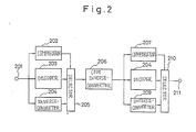
- a device for practicing a decoding method also embodying the present invention is shown which is constructed to recover the original information from the cryptogram outputted by the encoding device of Fig. 1.
- the decoding device has an input terminal 201, comparators 202 and 207, decoders 203 and 208, selectors 205 and 209, a code inverse-converter 206, and an output terminal 211.
- the cryptogram applied to the input terminal 201 is fed to the comparator 202, decoder 203 and inverse-converter 204.
- the comparator 202 compares the cryptogram, or numerical value, with the common key n and produces a ONE if the former is smaller than the latter while producing a ZERO if otherwise.
- the decoder 203 performs the conventional decoding operation corresponding to the encoder 108 with the input.
- the inverse-converter 204 applies a conversion opposite to the conversion performed by the converter 109 of Fig. 1 to the input numerical value.
- the selector 205 selects the output of the decoder 203 if the output of the comparator 202 is a ON and selects the output of the inverse-converter 204 if it is a ZERO.
- the code inverse-converter 206 applies a code conversion opposite to the code conversion performed by the encoder 106 of Fig. 1 thereto.
- the output of the code inverse-converter 206 is fed to the comparator 207, decoder 208, and inverse-converter 209.
- the comparator 207, decoder 208, inverse-converter 209 and selector 210 are related to each other in the same manner as the comparator 202, decoder 203, inverse-converter 204, and selector 205.
- the common key, decoding key and inverse conversion assigned to the selector 207, decoder 208, and inverse-converter 209 be in a particular relationship with those of the comparator 102, encoder 103, and, the converter 104: the same common key is shared by the selectors 102 and 207, encoder 103, and decoder 207, the decoding key of the decoder 208 corresponds to the encoding key of the encoder 103, and the inverse conversion performed by the inverse-converter 209 is opposite to the conversion performed by the inverse-converter 104.
- the output of the selector 210 is fed out via the output terminal 211 in the form of recovered information.
- the comparators 102, 107, 202 and 207 and the selectors 105, 110, 205 and 210 are implemented by a connection of a plurality of standard logic integrated circuits.
- the encoders 103 and 108 and the decoders 203 and 208 may each be implemented by a commercially available signal processor such as ⁇ PD77230 developed by NEC for signal processing purposes. This signal processor is described in a paper entitled “Exponential Computation Using Signal Processor", 1987 National Conference of the Institute of Electronic Data Communication Engineers of Japan, Treatises, No. 15, and a paper entitled “Implementation of RSA Cryptosystem by Signal Processor", 1988 National Conference of the Institute of Electronic Data Communication Engineers of Japan, Treatises, No. A-298.
- the converters 104 and 109 may each be constituted by a ROM (Read Only Memory), there is a fear that an eavesdropper finds the conversion procedure by reading data out of the ROM. That is, performing complicated conversions with the converters 104 and 109 is not so effective. For this reason and considering the intricacy of construction of the device, it is rather effective that each of the converters 104 and 109 produces its input without any conversion. In such a case, the inverse-converters 204 and 209 will also produce their inputs without applying any inverse conversion thereto.
- ROM Read Only Memory
- code converter 106 may also be implemented by a ROM, performing no complicated processing is rather effective for the same reason as discussed above in relation to the converters 104 and 109.
- a simple code conversion is available for converting a numerical value which is not smaller than the common key n to a number which is smaller than the common key n and setting up one-to-one correspondence between inputs and outputs, as follows.
- Fig. 3 shows a specific construction of the code converter 106 included in the encoding device of Fig. 1.
- a plurality of NOT circuits 306 are provided for inverting all the bits of the common key n which is applied to a terminal 301.
- An adder 303 adds the outputs of the NOT circuits 306 to a code which is fed thereto via an input terminal 302, the sum being fed out via an output terminal 305.
- the adder 303 has a carry input 304 to which a ONE is fed via a terminal 304. In this construction, the common key n is subtracted from the input code and the result is outputted.
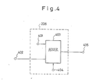
- Fig. 4 shows a specific construction of the code converter 206 included in the code inverse-converter 206.
- An adder 403 adds the common key n applied to a terminal 401 and a code applied to an input terminal 402, the sum being fed out via an output terminal 405.
- the adder 403 has a carry input to which a ZERO is applied via a terminal 404.
- Fig. 5 shows another specific construction of the code converter 106.
- a NOT circuit 502 inverts the most significant bit of a code which is fed thereto via an input terminal 501 and delivers the result via an output terminal 503. Lower bits of the input code are directly fed out via the output terminal 503.
- a code inverse-converter associated with the code converter will have the same construction as the latter.
- Fig. 6 shows still another specific construction of the code converter 106 which is implemented by a ROM 602.
- the ROM 602 has L address bits and stores L bits of predetermined data in each of its addresses. Upper L bits of a code coming in through an input terminal 601 are fed to the ROM 602 in the form of an address signal, so that data associated with those bits are read out of the ROM 601 and fed out via an output terminal 603. Lower bits of the input code are directly outputted via the output terminal 603.
- a code inverse-converter associated with a code converter having the above construction will have the same construction as the latter, but a ROM of the code inverse-converter should be loaded with data in such a manner as to effect code conversion inversely to the ROM 602.
- the encoding device is composed of input terminals 701 and 713, a comparator 702, an encoder 703, a converter 704, selectors 705 and 712, a code converter 706, and an output terminal 711.
- Information applied to the input terminal 701 is fed to the selector 712.
- the selector 712 first selects the information and delivers it to the comparator 702, encoder 703, and converter 704. Comparing the input numerical value with the common key n , the comparator 702 produces a ONE if the former is smaller than the latter and a ZERO if otherwise.
- the encoder 703 performs the conventional encoding operation with the input and produces the result.
- the converter 704 applies a predetermined one-to-one conversion to the input numerical value.
- the selector 705 selects the output of the encoder 703 if the output of the comparator 702 is a ONE and selects the output of the converter 704 if it is a ZERO.
- the code converter 706 effects a predetermined code conversion with the output of the converter 705, delivering an output thereof to the selector 712. Then, the selector 712 selects the output of the code converter 706, so that the above-described manipulations applied to the information are executed with the output of the code converter 706. Finally, the output of the selector 705 is fed out via the output terminal 711 in the form of a cryptogram.
- the selector 712 is switched over by a control signal which is applied to an input terminal 713.
- a control signal which is applied to an input terminal 713.
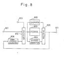
- the decoding device is made up of input terminals 801 and 813, a comparator 802, a decoder 803, an inverse-converter 804, selectors 805 and 812, a code inverse-converter 806, and an output terminal 811.
- a cryptogram applied to the input terminal 801 is fed to the selector 812.
- the selector 812 first selects the cryptogram and delivers it to the comparator 802, decoder 803, and inverse-converter 804. Comparing the input numerical value with the common key n , the comparator 802 produces a ONE if the former is smaller than the latter and a ZERO if otherwise.
- the decoder 803 decodes the input by using the conventional principle.
- the inverse-converter 804 applies a predetermined one-to-one conversion to the input numerical value.
- the selector 805 selects the output of the decoder 803 if the output of the comparator 802 is a ONE and selects the output of the inverse-converter 804 if it is a ZERO.
- Receiving the output of the selector 805, the code inverse-converter 806 performs a predetermined code inverse conversion with the input and feeds its output to the selector 812.
- the selector 812 selects the output of the code inverse-converter 806, so that the above operation applied to the cryptogram is executed with the output of the code inverse-converter 806.
- the output of the selector 805 is fed out in the form of recovered information.
- the selector 812 is switched over by a control signal which is applied to an input terminal 813.
- the decoding device of Fig. 7 uses common keys n (1), n (2), ..., n (M) and encoding keys e (1), e (2), ... e (M) in this order and decoding keys d (1), d (2), ..., d (M) are associated respectively with the encoding keys e (1), e (2), ... e (M), the decoding device should use the common keys n (M), ..., n (2), n (1) and the decoding keys d (M), d (2), ... d (1) in this order.
Abstract
Description
- The present invention relates to a method for encoding information into a code which cannot be deciphered by an eavesdropper and a method of decoding the code to recover the original information.
- Typical of encoding and decoding methods heretofore proposed is an RSA method which is disclosed by R.L. Rivest, A. Shamir and L. Addleman in a paper entitled "A Method for Obtaining Digital Signatures and Public-key Crypto-systems", Comm. ACM, Vol. 21, No. 2, pp. 120 - 126, 1978. For the convenience of description, the following description will concentrate only on a case wherein information is encoded into a cryptogram for the purpose of preventing an unauthorized person from eavesdropping the information. The encoding and decoding methods will be limited to the RSA method by way of example. Let the manipulation for converting information into a cryptogram and the manipulation for decoding a cryptogram into original information be called encoding and decoding, respectively. The encoding and decoding procedures according to the RSA method use an encoding key e and a decoding key d each being represented by a numerical value, and a common key n shared by both of encoding and decoding also being represented by a numerical value. These numerical values e, d, and n are predetermined integers. How to select the numerical values e, d, and n is not directly relevant to the present invention and therefore will not be described herein. The coding procedure particular to the RSA method begins with a step of obtaining a numerical representation P of information. Since information is usually rendered in the form of a bit sequence of (logical) ZEROs and (logical) ONEs, it will be automatically represented by a numerical value if the bit sequence is divided into blocks each having a finite length. In the following description, therefore, information and a numerical representation of information will not be distinguished from each other so long as there is no fear of confusion. A cryptogram C is obtained by applying to the information an arithmetic operation:
C = Pe mod n
Specifically, the information is raised to power e and then divided by n, the residual being the cryptogram C. To recover the original information P from the cryptogram C, the following arithmetic operation is performed:
P = Cd mod n
This equation means that the cryptogram C is raised to power d and then divided by n, the residue being the information P. - The RSA method, as discussed in the previously mentioned paper, is elaborated not only to prevent an unauthorized person from eavesdropping information but also to eliminate occurrences that a person transmitted information later denies the transmission for fraud and that an unauthorized person transmits information pretending to be an authorized person.
- A problem with the prior art encoding and decoding methods discussed above is that the information P has to be smaller than the common key n. Otherwise the information rendered by a numerical representation P and the information rendered by a numerical representation P+n would become indistinguishable because a residual produced by the division by the common key n is computed during the course of encoding operation. Further, to conform to the binary notation adopted fcr communications and computers, input information is usually divided such that the information P to be encoded is one bit shorter than the common key n. Moreover, since information applicable to communications and computers is managed by being fractioned to a length of 2's power such as 1024 bits, even the increase in the bit length by one amounts to an increase by 1024 in total. Thus, the prior art encoding method critically degrades the transmission of information and the efficiency of storage.
- It is therefore an object of the present invention to provide an encoding and a decoding method which eliminate the above-described shortcomings.
- In accordance with the present invention, an encoding method for producing a code associated with inputted information comprises the steps of (a) if a numerical representation of the inputted information is smaller than a predetermined numerical value, applying a predetermined operation to the information and producing as an interim result a residual remaining after a result of the operation is divided by the numerical value, (b) if the numerical representation of the inputted information is not smaller than the numerical value, applying a predetermined conversion to the information and producing a result of the conversion as an interim result, (c) applying a predetermined code conversion to the interium result and producing a result of the code conversion as a new interim result, (d) if the new interim result is smaller than the numerical value, applying the predetermined operation to the new interim result and producing as the code a residual remaining after a result of the predetermined operation is divided by the numerical value and (e) if the new interim result is not smaller than the predetermined numerical value, applying a predetermined conversion to the new interim result and producing a result of the conversion as the code.
- Further in accordance with the present invention, a decoding method for decoding an inputted code to produce information associated with the code comprises the steps of (a) if a numerical representation of the code is smaller than a predetermined numerical value, applying a predetermined operation to the code, and producing as an interim result a residual remaining after a result of the operation is divided by the numerical value, (b) if the numerical representation of the code is not smaller than the predetermined numerical value, applying a predetermined inverse-conversion to the code and outputting a result of the inverse-conversion as an interim result, (c) applying a predetermined code inverse-conversion to the interim result and outputting a result of the code inverse-conversion as a new interim result, (d) if the new interim result is smaller than the numerical value, applying a predetermined operation to the interim result and outputting as the information a residual remaining after a result of the operation is divided by the numerical value and (e) if the new interim result is not smaller than the numerical value, applying a predetermined inverse-conversion to the interim result and outputting a result of the inverse-conversion as the information.
- Other features and advantages of the invention will become apparent from the following description when taken in conjunction with the accompanying drawings in which:
- Fig. 1 is a schematic block diagram of a device for practicing an encoding method embodying the present invention;
- Fig.2 is a schematic block diagram of a device for practicing a decoding method embodying the present invention;
- Fig. 3 is a schematic block diagram showing a specific construction of a code converter included in the encoding device of Fig. 1;
- Fig. 4 is a schematic block diagram showing a specific construction of a code inverse-converter included in the decoding device of Fig. 2;
- Fig. 5 is a schematic block diagram showing another specific construction of the code converter included in the encoding device of Fig. 1;
- Fig. 6 is a schematic block diagram showing still another specific construction of the code converter of Fig. 1;
- Fig. 7 is a schematic block diagram representative of an alternative embodiment of the coding method in accordance with the present invention; and
- Fig. 8 is a schematic block diagram showing an alternative embodiment of the decoding method in accordance with the present invention.
- The principle of the present invention will be described before entering into detailed description of the preferred embodiments. In order to confine the bit length of a cryptogram within the bit length of information P, it is necessary that all the information and cryptograms shorter than a common key n with respect to bit length be associated one-to-one with each other. Otherwise, different information would be encoded into the same cryptogram and, hence, the original information would not be correctly recovered. With the prior art RSA method, it is possible to hold information and cryptograms which are shorter than the common key n with respect to bit length in one-to-one correspondence, only if keys e, d and n are skillfully selected. This is described in detail in the previously mentioned paper. It follows that the bit length of a cryptogram C can be prevented from becoming longer than that of information P by associating those information and cryptograms whose values are greater than the common key n one-to-one by a predetermined conversion. Information P may be encoded by the conventional method if it is smaller than the common key n, while it may be encoded by the conversion if it is greater than the common key n. This kind of encoding procedure will hereinafter be referred to as a bit-length preservation encoding method for convenience. A cryptogram C produced by the bit-length preservation encoding method may be decoded to obtain original information P by using the prior art method if it is smaller than the common key n, while such a cryptogram C may be decoded by applying an inverse conversion thereto if it is greater than the common key n. Such a decoding procedure will be referred to as a bit-length preserfation decoding method merely for convenience.
- A problem with the bit-length preservation encoding method is that, although the bit length does not increase, the information will be outputted after a simple conversion if the numerical representation P of the information is greater than the common key n. In the light of this, for those applications which need privacy, the following procedure is adopted. Specifically, inputs and outputs are held in one-to-one correspondence, and use is made of a code conversion which is such that in response to an inputted numerical value greater than the common key n a numerical value which is smaller than the common key n is outputted. Such a code conversion is applied to a cryptogram produced by the bit-length preservation encoding method, and then the bit-length preservation encoding method is effected again with the code-converted cryptogram. This allows all the information to be encoded. To recover the original information from the information which has been encoded by the above method, the bit-length preservation decoding method is practiced with the cryptogram. Then, an inverse conversion opposite to the above code conversion is applied to the resulting data, followed by the bit-length preservation decoding again.
- While the present invention has been discussed above in relation to the RSA method only, it will be apparent that it is similarly applicable to any other encoding and decoding procedures of the kind performing a predetermined arithmetic operation with input data, dividing the result of arithmetic operation by a given numerical value, and outputting the residual. This is because the present invention adopts, among various properties of the RSA method, only the property that information and cryptograms which are smaller than the common key n are associated one-to-one with each other, and because this property is also true with the previously discussed general encoding and decoding methods.
- The above description has concentrated on preventing an unauthorized person from eavesdropping information. The present invention is also successful in eliminating occurrences that one transmitted information later denies the transmission for fraud and that an unauthorized person transmits false information pretending to be an authorized person. It will be clear from the previously mentioned paper that combining the encoding and decoding procedures particular to the present invention implements the above alternative purposes.
- Referring to Fig. 1 of the drawings, a device for practicing an encoding method embodying the present invention is shown. In the figure, the encoding device is generally made up of an
input terminal 101,comparators encoders converters selectors code converter 106, and anoutput terminal 111. Information coming in through theinput terminal 101 is fed to thecomparator 102,encoder 103, andconverter 104. Thecomparator 102 compares the input information, or numerical value, with a common key n and produces a (logical) ONE if the input value is smaller than the common key n and a (logical) ZERO if otherwise. Theencoder 103 encodes the input by using the RSA method or similar conventional encoding method and produces the result. Theconverter 104 converts the input information, i.e., the numerical value on a predetermined one-to-one basis. Theselector 105 selects the output of theencoder 103 if the output of thecomparator 102 is a ONE and selects the output of theconverter 104 if it is a ZERO. Receiving the output of theselector 105, thecode converter 106 applies a predetermined code conversion thereto and delivers the result to thecomparator 107,encoder 108, andconverter 109. While the relationship between thecomparator 107,encoder 108,converter 109 andselector 110 is the same as the relationship between thecomparator 102,encoder 103,converter 104 andselector 105, it is not necessary that the former shares the same common key, encoding key and a conversion with the latter. The output of theselector 110 is fed out via theoutput terminal 111 in the form of a cryptogram. - Referring to Fig. 2, a device for practicing a decoding method also embodying the present invention is shown which is constructed to recover the original information from the cryptogram outputted by the encoding device of Fig. 1. As shown, the decoding device has an
input terminal 201,comparators decoders 203 and 208,selectors converter 206, and anoutput terminal 211. The cryptogram applied to theinput terminal 201 is fed to thecomparator 202,decoder 203 and inverse-converter 204. Thecomparator 202 compares the cryptogram, or numerical value, with the common key n and produces a ONE if the former is smaller than the latter while producing a ZERO if otherwise. Thedecoder 203 performs the conventional decoding operation corresponding to theencoder 108 with the input. The inverse-converter 204 applies a conversion opposite to the conversion performed by theconverter 109 of Fig. 1 to the input numerical value. Theselector 205 selects the output of thedecoder 203 if the output of thecomparator 202 is a ON and selects the output of the inverse-converter 204 if it is a ZERO. Receiving the output of theselector 205, the code inverse-converter 206 applies a code conversion opposite to the code conversion performed by theencoder 106 of Fig. 1 thereto. The output of the code inverse-converter 206 is fed to thecomparator 207, decoder 208, and inverse-converter 209. Thecomparator 207, decoder 208, inverse-converter 209 andselector 210 are related to each other in the same manner as thecomparator 202,decoder 203, inverse-converter 204, andselector 205. However, a prerequisite is that the common key, decoding key and inverse conversion assigned to theselector 207, decoder 208, and inverse-converter 209 be in a particular relationship with those of thecomparator 102,encoder 103, and, the converter 104: the same common key is shared by theselectors encoder 103, anddecoder 207, the decoding key of the decoder 208 corresponds to the encoding key of theencoder 103, and the inverse conversion performed by the inverse-converter 209 is opposite to the conversion performed by the inverse-converter 104. The output of theselector 210 is fed out via theoutput terminal 211 in the form of recovered information. - The
comparators selectors encoders decoders 203 and 208 may each be implemented by a commercially available signal processor such as µPD77230 developed by NEC for signal processing purposes. This signal processor is described in a paper entitled "Exponential Computation Using Signal Processor", 1987 National Conference of the Institute of Electronic Data Communication Engineers of Japan, Treatises, No. 15, and a paper entitled "Implementation of RSA Cryptosystem by Signal Processor", 1988 National Conference of the Institute of Electronic Data Communication Engineers of Japan, Treatises, No. A-298. - Although the
converters converters converters converters - While the
code converter 106 may also be implemented by a ROM, performing no complicated processing is rather effective for the same reason as discussed above in relation to theconverters - Fig. 3 shows a specific construction of the
code converter 106 included in the encoding device of Fig. 1. In the figure, a plurality ofNOT circuits 306 are provided for inverting all the bits of the common key n which is applied to a terminal 301. Anadder 303 adds the outputs of theNOT circuits 306 to a code which is fed thereto via aninput terminal 302, the sum being fed out via anoutput terminal 305. Theadder 303 has acarry input 304 to which a ONE is fed via aterminal 304. In this construction, the common key n is subtracted from the input code and the result is outputted. - Fig. 4 shows a specific construction of the
code converter 206 included in the code inverse-converter 206. Anadder 403 adds the common key n applied to a terminal 401 and a code applied to aninput terminal 402, the sum being fed out via anoutput terminal 405. Theadder 403 has a carry input to which a ZERO is applied via aterminal 404. - Fig. 5 shows another specific construction of the
code converter 106. In the figure, aNOT circuit 502 inverts the most significant bit of a code which is fed thereto via aninput terminal 501 and delivers the result via anoutput terminal 503. Lower bits of the input code are directly fed out via theoutput terminal 503. When use is made of such a code converter, a code inverse-converter associated with the code converter will have the same construction as the latter. - Fig. 6 shows still another specific construction of the
code converter 106 which is implemented by aROM 602. TheROM 602 has L address bits and stores L bits of predetermined data in each of its addresses. Upper L bits of a code coming in through aninput terminal 601 are fed to theROM 602 in the form of an address signal, so that data associated with those bits are read out of theROM 601 and fed out via anoutput terminal 603. Lower bits of the input code are directly outputted via theoutput terminal 603. A code inverse-converter associated with a code converter having the above construction will have the same construction as the latter, but a ROM of the code inverse-converter should be loaded with data in such a manner as to effect code conversion inversely to theROM 602. - Referring to Fig. 7, an alternative embodiment of the encoding method in accordance with the present invention is shown. As shown, the encoding device is composed of
input terminals comparator 702, anencoder 703, aconverter 704,selectors code converter 706, and anoutput terminal 711. Information applied to theinput terminal 701 is fed to theselector 712. Theselector 712 first selects the information and delivers it to thecomparator 702,encoder 703, andconverter 704. Comparing the input numerical value with the common key n, thecomparator 702 produces a ONE if the former is smaller than the latter and a ZERO if otherwise. Theencoder 703 performs the conventional encoding operation with the input and produces the result. Theconverter 704 applies a predetermined one-to-one conversion to the input numerical value. Theselector 705 selects the output of theencoder 703 if the output of thecomparator 702 is a ONE and selects the output of theconverter 704 if it is a ZERO. Thecode converter 706 effects a predetermined code conversion with the output of theconverter 705, delivering an output thereof to theselector 712. Then, theselector 712 selects the output of thecode converter 706, so that the above-described manipulations applied to the information are executed with the output of thecode converter 706. Finally, the output of theselector 705 is fed out via theoutput terminal 711 in the form of a cryptogram. Theselector 712 is switched over by a control signal which is applied to aninput terminal 713. With the encoding device of Fig. 7, it is possible to repeat the above operation applied to information more than two times by repeating the feedback of the output of theselector 705 to thecode converter 706. For each of such repetitive operations, use may be made of a different common key and a different encoding key. - Referring to Fig. 8, an alternative embodiment of the decoding method in accordance with the present invention is shown. As shown, the decoding device is made up of
input terminals comparator 802, adecoder 803, an inverse-converter 804,selectors converter 806, and anoutput terminal 811. A cryptogram applied to theinput terminal 801 is fed to theselector 812. Theselector 812 first selects the cryptogram and delivers it to thecomparator 802,decoder 803, and inverse-converter 804. Comparing the input numerical value with the common key n, thecomparator 802 produces a ONE if the former is smaller than the latter and a ZERO if otherwise. Thedecoder 803 decodes the input by using the conventional principle. The inverse-converter 804 applies a predetermined one-to-one conversion to the input numerical value. Theselector 805 selects the output of thedecoder 803 if the output of thecomparator 802 is a ONE and selects the output of the inverse-converter 804 if it is a ZERO. Receiving the output of theselector 805, the code inverse-converter 806 performs a predetermined code inverse conversion with the input and feeds its output to theselector 812. At this time, theselector 812 selects the output of the code inverse-converter 806, so that the above operation applied to the cryptogram is executed with the output of the code inverse-converter 806. The output of theselector 805 is fed out in the form of recovered information. Theselector 812 is switched over by a control signal which is applied to aninput terminal 813. With the construction of Fig. 8, it is possible to repeat the above operation more than two times by repeating the feedback of the output of theselector 805 to the code inverse-converter 806. The number of times of repetition should be the same as that of the encoding device of Fig. 7. In the device shown in Fig. 8, a different common key and a different decoding key may be assigned to each of the repetitive operations. It is to be noted, however, that when the coding device of Fig. 7 uses common keys n(1), n(2), ..., n(M) and encoding keys e(1), e(2), ... e(M) in this order and decoding keys d(1), d(2), ..., d(M) are associated respectively with the encoding keys e(1), e(2), ... e(M), the decoding device should use the common keys n(M), ..., n(2), n(1) and the decoding keys d(M), d(2), ... d(1) in this order. - While the present invention has been described in conjunction with the preferred embodiments thereof, it will now readily be possible for those skilled in the art to put the present invention into practice in various other manners.
Claims (11)
Applications Claiming Priority (2)
| Application Number | Priority Date | Filing Date | Title |
|---|---|---|---|
| JP108643/88 | 1988-04-28 | ||
| JP63108643A JP2871690B2 (en) | 1988-04-28 | 1988-04-28 | Encoding device and decoding device |
Publications (3)
| Publication Number | Publication Date |
|---|---|
| EP0340633A2 true EP0340633A2 (en) | 1989-11-08 |
| EP0340633A3 EP0340633A3 (en) | 1992-01-22 |
| EP0340633B1 EP0340633B1 (en) | 1996-08-28 |
Family
ID=14490002
Family Applications (1)
| Application Number | Title | Priority Date | Filing Date |
|---|---|---|---|
| EP89107634A Expired - Lifetime EP0340633B1 (en) | 1988-04-28 | 1989-04-27 | Encoding and decoding method and apparatus |
Country Status (6)
| Country | Link |
|---|---|
| US (1) | US5068895A (en) |
| EP (1) | EP0340633B1 (en) |
| JP (1) | JP2871690B2 (en) |
| AU (1) | AU630090B2 (en) |
| CA (1) | CA1330597C (en) |
| DE (1) | DE68927020T2 (en) |
Cited By (1)
| Publication number | Priority date | Publication date | Assignee | Title |
|---|---|---|---|---|
| EP0667692A2 (en) * | 1994-02-14 | 1995-08-16 | Nec Corporation | Public-key cryptographic apparatus handling ciphertext by public-key |
Families Citing this family (6)
| Publication number | Priority date | Publication date | Assignee | Title |
|---|---|---|---|---|
| EP0648031B1 (en) * | 1993-10-12 | 2007-08-01 | Matsushita Electric Industrial Co., Ltd. | Audio scrambling system for scrambling and descrambling audio signals |
| US5673319A (en) * | 1995-02-06 | 1997-09-30 | International Business Machines Corporation | Block cipher mode of operation for secure, length-preserving encryption |
| JP2002252420A (en) * | 2000-12-15 | 2002-09-06 | Furukawa Electric Co Ltd:The | Semiconductor laser device, semiconductor laser module and its manufacturing method, and optical fiber amplifier |
| DE10110049A1 (en) * | 2001-03-02 | 2002-09-05 | Bosch Gmbh Robert | Encryption of program data for use in control devices or controllers, involves using decryption key within the control device, to reduce the amount of data to transfer |
| JP4715748B2 (en) * | 2004-03-31 | 2011-07-06 | 日本電気株式会社 | How to apply padding to ensure the security of cryptography |
| US7917523B2 (en) * | 2006-04-05 | 2011-03-29 | Cisco Technology, Inc. | Method and system for providing improved URL mangling performance using fast re-write |
Citations (1)
| Publication number | Priority date | Publication date | Assignee | Title |
|---|---|---|---|---|
| US4405829A (en) * | 1977-12-14 | 1983-09-20 | Massachusetts Institute Of Technology | Cryptographic communications system and method |
Family Cites Families (3)
| Publication number | Priority date | Publication date | Assignee | Title |
|---|---|---|---|---|
| US4078152A (en) * | 1976-04-26 | 1978-03-07 | International Business Machines Corporation | Block-cipher cryptographic system with chaining |
| US4752953A (en) * | 1983-05-27 | 1988-06-21 | M/A-Com Government Systems, Inc. | Digital audio scrambling system with pulse amplitude modulation |
| US4896353A (en) * | 1988-09-23 | 1990-01-23 | Unisys Corp. | Apparatus for fast decoding of a non-linear code |
-
1988
- 1988-04-28 JP JP63108643A patent/JP2871690B2/en not_active Expired - Lifetime
-
1989
- 1989-04-26 US US07/343,338 patent/US5068895A/en not_active Expired - Lifetime
- 1989-04-27 AU AU33780/89A patent/AU630090B2/en not_active Expired
- 1989-04-27 EP EP89107634A patent/EP0340633B1/en not_active Expired - Lifetime
- 1989-04-27 CA CA000597977A patent/CA1330597C/en not_active Expired - Lifetime
- 1989-04-27 DE DE68927020T patent/DE68927020T2/en not_active Expired - Lifetime
Patent Citations (1)
| Publication number | Priority date | Publication date | Assignee | Title |
|---|---|---|---|---|
| US4405829A (en) * | 1977-12-14 | 1983-09-20 | Massachusetts Institute Of Technology | Cryptographic communications system and method |
Non-Patent Citations (1)
| Title |
|---|
| COMMUNICATIONS OF THE ASSOCIATION FOR COMPUTING MACHINERY. vol. 21, no. 2, February 1978, NEW YORK US pages 120 - 126; RIVEST ET AL: 'A Method for Obtaining Digital Signatures and Public-Key Cryptosystems' * |
Cited By (2)
| Publication number | Priority date | Publication date | Assignee | Title |
|---|---|---|---|---|
| EP0667692A2 (en) * | 1994-02-14 | 1995-08-16 | Nec Corporation | Public-key cryptographic apparatus handling ciphertext by public-key |
| EP0667692A3 (en) * | 1994-02-14 | 1996-10-16 | Nec Corp | Public-key cryptographic apparatus handling ciphertext by public-key. |
Also Published As
| Publication number | Publication date |
|---|---|
| AU630090B2 (en) | 1992-10-22 |
| EP0340633A3 (en) | 1992-01-22 |
| DE68927020D1 (en) | 1996-10-02 |
| DE68927020T2 (en) | 1997-01-23 |
| JPH01277280A (en) | 1989-11-07 |
| EP0340633B1 (en) | 1996-08-28 |
| US5068895A (en) | 1991-11-26 |
| CA1330597C (en) | 1994-07-05 |
| JP2871690B2 (en) | 1999-03-17 |
| AU3378089A (en) | 1989-11-02 |
Similar Documents
| Publication | Publication Date | Title |
|---|---|---|
| Jones | An efficient coding system for long source sequences | |
| EP0511420B1 (en) | A cryptographic system based on information difference | |
| EP0267647A2 (en) | Enciphering/deciphering method and arrangement for performing the method | |
| GB2094113A (en) | Improvements in or relating to cryptography | |
| KR20070084197A (en) | Cryptographic primitives, error coding, and pseudo-random number improvement methods using quasigroups | |
| EP0011615A1 (en) | Method and device for encryption and decryption of data. | |
| Kim et al. | A secure information transmission scheme with a secret key based on polar coding | |
| US4969190A (en) | Encrypting system of data | |
| US6252960B1 (en) | Compression and decompression of elliptic curve data points | |
| EP0340633B1 (en) | Encoding and decoding method and apparatus | |
| US20050188200A1 (en) | System and method for authentication | |
| EP3447963A1 (en) | Method for protecting data | |
| CN112926075A (en) | SM9 key generation method, device, equipment and storage medium | |
| CN112529974A (en) | Color visual password sharing method and device for binary image | |
| CN112235319A (en) | Data encryption and decryption method and device and encryption and decryption circuit | |
| EP0506405B1 (en) | Image transmission method, and apparatus therefor | |
| JP2009169316A (en) | Hash function operational device, signature device, program and hash function operational method | |
| CN116094716A (en) | Text encryption and decryption method, system and equipment based on elliptic curve cryptography | |
| JP2824910B2 (en) | How to combine data into an image | |
| JP2864813B2 (en) | Encryption device and decryption device | |
| CA2141997C (en) | Public-key cryptographic apparatus handling ciphertext by public-key | |
| EP0399587B1 (en) | Method for enciphering a series consisting of at least one symbol | |
| JP3055636B2 (en) | Encryption communication encoding device and decoding device | |
| JPH06339036A (en) | Ciphering device and method for facsimile equipment | |
| EP0768772A2 (en) | Method and apparatus for transmission of low-rate telemetry data as auxiliary data on a main channel |
Legal Events
| Date | Code | Title | Description |
|---|---|---|---|
| PUAI | Public reference made under article 153(3) epc to a published international application that has entered the european phase |
Free format text: ORIGINAL CODE: 0009012 |
|
| 17P | Request for examination filed |
Effective date: 19890427 |
|
| AK | Designated contracting states |
Kind code of ref document: A2 Designated state(s): BE DE FR GB NL SE |
|
| PUAL | Search report despatched |
Free format text: ORIGINAL CODE: 0009013 |
|
| AK | Designated contracting states |
Kind code of ref document: A3 Designated state(s): BE DE FR GB NL SE |
|
| 17Q | First examination report despatched |
Effective date: 19940407 |
|
| GRAH | Despatch of communication of intention to grant a patent |
Free format text: ORIGINAL CODE: EPIDOS IGRA |
|
| GRAA | (expected) grant |
Free format text: ORIGINAL CODE: 0009210 |
|
| GRAH | Despatch of communication of intention to grant a patent |
Free format text: ORIGINAL CODE: EPIDOS IGRA |
|
| AK | Designated contracting states |
Kind code of ref document: B1 Designated state(s): BE DE FR GB NL SE |
|
| REF | Corresponds to: |
Ref document number: 68927020 Country of ref document: DE Date of ref document: 19961002 |
|
| ET | Fr: translation filed | ||
| PLBE | No opposition filed within time limit |
Free format text: ORIGINAL CODE: 0009261 |
|
| STAA | Information on the status of an ep patent application or granted ep patent |
Free format text: STATUS: NO OPPOSITION FILED WITHIN TIME LIMIT |
|
| 26N | No opposition filed | ||
| REG | Reference to a national code |
Ref country code: GB Ref legal event code: IF02 |
|
| PGFP | Annual fee paid to national office [announced via postgrant information from national office to epo] |
Ref country code: FR Payment date: 20080312 Year of fee payment: 20 Ref country code: DE Payment date: 20080502 Year of fee payment: 20 |
|
| PGFP | Annual fee paid to national office [announced via postgrant information from national office to epo] |
Ref country code: BE Payment date: 20080616 Year of fee payment: 20 |
|
| PGFP | Annual fee paid to national office [announced via postgrant information from national office to epo] |
Ref country code: NL Payment date: 20080415 Year of fee payment: 20 Ref country code: SE Payment date: 20080408 Year of fee payment: 20 |
|
| PGFP | Annual fee paid to national office [announced via postgrant information from national office to epo] |
Ref country code: GB Payment date: 20080430 Year of fee payment: 20 |
|
| BE20 | Be: patent expired |
Owner name: *NEC CORP. Effective date: 20090427 |
|
| REG | Reference to a national code |
Ref country code: GB Ref legal event code: PE20 Expiry date: 20090426 |
|
| PG25 | Lapsed in a contracting state [announced via postgrant information from national office to epo] |
Ref country code: NL Free format text: LAPSE BECAUSE OF EXPIRATION OF PROTECTION Effective date: 20090427 |
|
| EUG | Se: european patent has lapsed | ||
| NLV7 | Nl: ceased due to reaching the maximum lifetime of a patent |
Effective date: 20090427 |
|
| PG25 | Lapsed in a contracting state [announced via postgrant information from national office to epo] |
Ref country code: GB Free format text: LAPSE BECAUSE OF EXPIRATION OF PROTECTION Effective date: 20090426 |