EP0341533A1 - Dispensing closure for liquid-containers - Google Patents
Dispensing closure for liquid-containers Download PDFInfo
- Publication number
- EP0341533A1 EP0341533A1 EP89107867A EP89107867A EP0341533A1 EP 0341533 A1 EP0341533 A1 EP 0341533A1 EP 89107867 A EP89107867 A EP 89107867A EP 89107867 A EP89107867 A EP 89107867A EP 0341533 A1 EP0341533 A1 EP 0341533A1
- Authority
- EP
- European Patent Office
- Prior art keywords
- flange
- closure
- container
- connecting piece
- removal
- Prior art date
- Legal status (The legal status is an assumption and is not a legal conclusion. Google has not performed a legal analysis and makes no representation as to the accuracy of the status listed.)
- Granted
Links
Images
Classifications
-
- B—PERFORMING OPERATIONS; TRANSPORTING
- B65—CONVEYING; PACKING; STORING; HANDLING THIN OR FILAMENTARY MATERIAL
- B65D—CONTAINERS FOR STORAGE OR TRANSPORT OF ARTICLES OR MATERIALS, e.g. BAGS, BARRELS, BOTTLES, BOXES, CANS, CARTONS, CRATES, DRUMS, JARS, TANKS, HOPPERS, FORWARDING CONTAINERS; ACCESSORIES, CLOSURES, OR FITTINGS THEREFOR; PACKAGING ELEMENTS; PACKAGES
- B65D47/00—Closures with filling and discharging, or with discharging, devices
- B65D47/04—Closures with discharging devices other than pumps
- B65D47/06—Closures with discharging devices other than pumps with pouring spouts or tubes; with discharge nozzles or passages
- B65D47/12—Closures with discharging devices other than pumps with pouring spouts or tubes; with discharge nozzles or passages having removable closures
Definitions
- the closure flange 1 there is an eyeglass plate 16 which has openings 17, 18 through which the connecting pieces 7 and 13 protrude.
- the edge of the spectacle plate 16 protrudes on all sides beyond the circumference of the closure flange 1.
- flange screws 20 are arranged in bores 19, which are only indicated in FIG. 1 and which are used for connection to the container flange 2.
Landscapes
- Engineering & Computer Science (AREA)
- Mechanical Engineering (AREA)
- Closures For Containers (AREA)
Abstract
Description
Die Erfindung betrifft einen Entnahmeverschluß für mit einem Behälterflansch an einer Behälteröffnung verseheneThe invention relates to a removal closure for those provided with a container flange at a container opening
Flüssigkeitsbehälter für hochreine flüssige Chemikalien, mit einem Verschlußflansch, der mittels Flanschschrauben mit dem Behälterflansch verbindbar ist, einem Tauchrohr, das von einem oberen Anschlußstutzen durch den Verschlußflansch hindurch nach unten ragt und mit diesem verbunden ist, und mit mindestens einem weiteren, mit dem Verschlußflansch verbundenen Anschlußstutzen.Liquid container for high-purity liquid chemicals, with a closure flange which can be connected to the container flange by means of flange screws, an immersion tube which projects downwards from an upper connection piece through the closure flange and is connected to the latter, and with at least one further connection to the closure flange Connecting piece.
Bei der Herstellung von elektronischen Bauelementen und in anderen Einsatzbereichen werden in vielen Fällen flüssige Chemikalien benötigt, an deren Reinheit höchste Ansprüche gestellt werden. Beim Transport, der Lagerung und der Handhabung müssen jegliche Verunreinigungen dieser Chemikalien vermieden werden. Außerdem ist zu berücksichtigen, daß diese Chemikalien in vielen Fällen giftig oder in anderer Weise schädlich sind. Dadurch ergeben sich einerseits hohe Anforderungen an die verwendeten Transport- und Lagerbehälter, andererseits insbesondere aber an deren Entnahmeverschlüsse, die so gestaltet sein müssen, daß beim Transport und bei der Lagerung ein sicherer Verschluß des Behälters gewährleistet ist und daß bei der Befüllung oder Entnahme und auch bei den Vorbereitungen hierzu jegliche Fehlermöglichkeiten weitestgehend ausgeschlossen sind, die zu einer Verunreinigung und/oder einem unbeabsichtigten Flüssigkeitsaustritt führen könnten. Aus diesen Gründen werden an die Materialauswahl und die Konstruktion der Entnahmeverschlüsse sehr strenge Anforderungen gestellt.In the production of electronic components and in other areas of application, liquid chemicals are required in many cases. Any contamination of these chemicals must be avoided during transport, storage and handling. It should also be borne in mind that in many cases these chemicals are toxic or otherwise harmful. This results on the one hand in high demands on the transport and storage containers used, and on the other hand in particular on their removal closures, which must be designed in such a way that a secure closure during transport and storage of the container is guaranteed and that during the filling or removal and also during the preparations for this, any possible errors that can lead to contamination and / or an unintentional leakage of liquid are largely excluded. For these reasons, very strict requirements are placed on the choice of material and the design of the extraction closures.
Bisher ist es üblich, die Entnahmeverschlüsse aus PTFE (Polytetrafluoräthylen) herzustellen, um jegliche Reaktion des Werkstoffs mit den flüssigen Chemikalien auszuschließen. Da eine Schweißverbindung von PTFE nicht möglich ist, sind die gebräuchlichen Entnahmeverschlüsse als Schraubkonstruktion ausgeführt, wobei auch das Tauchrohr in den Verschlußflansch eingeschraubt ist.So far, it has been customary to manufacture the extraction closures from PTFE (polytetrafluoroethylene) in order to prevent any reaction of the material with the liquid chemicals. Since a welded connection of PTFE is not possible, the usual extraction closures are designed as a screw construction, whereby the immersion tube is also screwed into the closure flange.
Sowohl beim Anbringen und Lösen der Verbindung des Anschlußstutzens des Tauchrohrs mit den Rohrleitungen zum Befüllen und zur Flüssigkeitsentnahme als auch beim Verschließen mittels einer Schraubkappe besteht dabei jedoch die Gefahr, daß das aufgebrachte Schraubmoment zum Lösen der Schraubverbindung zwischen dem Tauchrohr und dem Verschlußflansch führt. Das gleiche gilt für die Schraubverbindung zwischen dem weiteren Anschlußstutzen, der für den Gasanschluß vorgesehen ist. Wenn die Verbindung zwischen diesen Anschlußstutzen und dem Verschlußflansch auf die beschriebene Weise unbeabsichtigt gelockert wurde, ist die Dichtheit des Behälters im Bereich des Entnahmeverschlusses nicht mehr gewährleistet. Es besteht die Gefahr des Austritts von Flüssigkeit und/oder des Eintritts von Verunreinigungen.Both when attaching and detaching the connection piece of the immersion tube to the pipelines for filling and for removing liquid, and also when closing by means of a screw cap, there is a risk that the screwing torque applied leads to the loosening of the screw connection between the immersion tube and the closure flange. The same applies to the screw connection between the further connecting piece which is provided for the gas connection. If the connection between these connecting pieces and the closure flange has been unintentionally loosened in the manner described, the tightness of the container in the region of the removal closure is no longer guaranteed. There is a risk of liquid leakage and / or contamination.
Aufgabe der Erfindung ist es daher, einen Entnahmeverschluß der eingangs genannten Gattung so auszubilden, daß die Betriebssicherheit erhöht wird und insbesondere keine Gefahr mehr besteht, daß sich beim Aufbringen eines Schraubmoments an die aus dem Verschlußflansch herausragenden Anschlußstutzen eine Schraubverbindung mit dem Verschlußflansch in unbeabsichtigter Weise lockern könnte.The object of the invention is therefore to design a removal closure of the type mentioned in such a way that operational safety is increased and in particular there is no longer any risk that the Applying a screw torque to the connecting piece protruding from the closure flange could loosen a screw connection with the closure flange in an unintentional manner.
Diese Aufgabe wird erfindungsgemäß dadurch gelöst, daß der Verschlußflansch, das Tauchrohr mit seinem oberen Anschlußstutzen sowie der weitere Anschlußstutzen einstückig als Kunststoff-Spritzgußteil ausgeführt sind. Dadurch kann zwischen diesen Anschlußstutzen einerseits und dem Verschlußflansch andererseits keine Undichtheit mehr auftreten, auch wenn unzulässig hohe Schraubmomente an den Anschlußstutzen aufgebracht wurden.This object is achieved in that the closure flange, the immersion tube with its upper connection piece and the further connection piece are made in one piece as a plastic injection molded part. As a result, leakage can no longer occur between these connecting pieces on the one hand and the closure flange on the other hand, even if impermissibly high screw torques have been applied to the connecting pieces.
Vorzugsweise beseht dieses Kunststoff-Spritzgußteil aus einem fluorierten Thermoplast, insbesondere PFA (Perfluoralkoxy-Copolymer).This plastic injection molded part is preferably made of a fluorinated thermoplastic, in particular PFA (perfluoroalkoxy copolymer).
Weitere vorteilhafte Ausgestaltungen des Erfindungsgedankens sind Gegenstand weiterer Unteransprüche.Further advantageous embodiments of the inventive concept are the subject of further dependent claims.
Nachfolgend wird ein Ausführungsbeispiel der Erfindung näher erläutert, das in der Zeichnung dargestellt ist. Es zeigt:
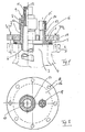
- Fig. 1 in einem senkrechten Schnitt einen Entnahmeverschluß für einen Flüssigkeitsbehälter für hochreine flüssige Chemikalien und
- Fig. 2 eine Draufsicht auf den Entnahmeverschluß nach Fig. 1 mit abgenommenen Verschlußteilen.
- Fig. 1 in a vertical section a removal closure for a liquid container for high-purity liquid chemicals and
- Fig. 2 is a plan view of the removal closure of FIG. 1 with the closure parts removed.
Der in der Zeichnung dargestelte Entnahmeverschluß weist einen Verschlußflansch 1 auf, der an der Oberseite eines nur mit strichpunktierten Linien angedeuteten Behälterflanschs 2 anliegt. Der Behälterflansch 2 umgibt eine Behälteröffnung 3 eines Flüssigkeitsbehälters 4, der in der Zeichnung nur teilweise dargestellt ist und der zur Aufnahme von hochreinen flüssigen Chemikalien bestimmt ist, wie sie beispielsweise in der elektronischen Halbleiterfertigung Verwendung finden. Zwischen dem Verschlußflansch 1 und dem Behälterflansch 2 ist ein Dichtring 5 eingelegt.The removal closure shown in the drawing has a closure flange 1, which rests on the top of a
Ein einstückig mit dem Verschlußflansch 1 verbundenes Tauchrohr 6 ragt nach unten in den Flüssigkeitsbehälter 4 und dient zur Entnahme der Flüssigkeit. Nach oben schließt sich an das Tauchrohr 6 ein Anschlußstutzen 7 an, auf dem mittels einer Überwurf-Schraubkappe 8 ein Einsatzstutzen 9 gehalten wird. Nach innen vorspringende Rippen 10 greifen in seitliche Nuten des Einsatzstutzens 9 und halten diesen undrehbar am Anschlußstutzen 7 fest. Der Einsatzstutzen 9 trägt einen Gewindeanschluß 11, der mittels einer Schraubkappe 12 beim Transport und bei der Lagerung verschlossen ist. Der Gewindeanschluß 11 dient beim Befüllen und bei der Flüssigkeitsentnahme zum Anschluß einer Rohrleitung.An immersion tube 6, which is connected in one piece to the closure flange 1, projects downward into the
Neben dem Anschlußstutzen 7 ist üblicherweise mindestens ein weiterer Anschlußstutzen 13 an der Oberseite des Verschlußflansches 1 angeordnet, der ebenfalls einstückig mit diesem ausgeführt ist. Der Anschlußstutzen 13, dessen Gewindeanschluß 14 ebenfalls mittels einer Schraubkappe 15 verschließbar oder mit einer Rohrleitung verbindbar ist, dient beispielsweise zur Gaszufuhr bei der Flüssigkeitsentnahme.In addition to the connecting piece 7, at least one further connecting
Auf dem Verschlußflansch 1 liegt eine Brillenplatte 16 auf, die Durchbrechungen 17, 18 aufweist, durch die die Anschlußstutzen 7 und 13 ragen. Der Rand der Brillenplatte 16 ragt allseitig über den Umfang des Verschlußflanschs 1 hinaus. An diesem Rand der Brillenplatte 16 sind in Bohrungen 19 Flanschschrauben 20 angeordnet, die in Fig. 1 nur angedeutet sind und die zur Verbindung mit dem Behälterflansch 2 dienen. Mittels der Flanschschrauben 20 wird die Brillenplatte 16 und somit auch der Verschlußflansch 1 gegen den Behälterflansch 2 gepreßt.On the closure flange 1 there is an
Der Verschlußflansch 1, das Tauchrohr 6 mit seinem oberen Anschlußstutzen 7 sowie der weitere Anschlußstutzen 13 sind einstückig als Kunststoff-Spritzgußteil aus PFA hergestellt. Punktförmige oder einseitige Belastungen des Verschlußflanschs 1 werden dadurch vermieden, daß die Brillenplate 16 die von den Flanschschrauben 20 aufgebrachten Kräfte gleichmäßig auf den Verschlußflansch 1 überträgt. Wenn beim Anbringen oder Lösen der Schraubkappen 12, 15 oder beim Anschließen oder Abnehmen von Rohrverschraubungen an den Gewindeanschlüssen 11, 14 hohe Schraubmomente aufgebracht werden, besteht gleichwohl keine Gefahr, daß die Verbindung der Anschlußstutzen 7 bzw. 13 mit dem Verschlußflansch 1 gelöst oder gelockert werden könnte. Die Übertragung des Schraubmoments auf die Überwurf-Schraubkappe 8 wird durch die formschlüssige und drehfeste Verbindung des Einsatzstutzens 9 mit dem Anschlußstutzen 7 verhindert.The closure flange 1, the dip tube 6 with its upper connecting piece 7 and the further connecting
Ein unbeabsichtigtes Lösen von Teilen des Entnahmeverschlusses ist ausgeschlossen, so daß die Betriebssicherheit erhöht wird.Unintentional loosening of parts of the removal lock is excluded, so that operational safety is increased.
Claims (4)
Applications Claiming Priority (2)
| Application Number | Priority Date | Filing Date | Title |
|---|---|---|---|
| DE3815623 | 1988-05-07 | ||
| DE3815623A DE3815623A1 (en) | 1988-05-07 | 1988-05-07 | DISCHARGE LOCK FOR LIQUID CONTAINERS |
Publications (2)
| Publication Number | Publication Date |
|---|---|
| EP0341533A1 true EP0341533A1 (en) | 1989-11-15 |
| EP0341533B1 EP0341533B1 (en) | 1993-06-16 |
Family
ID=6353877
Family Applications (1)
| Application Number | Title | Priority Date | Filing Date |
|---|---|---|---|
| EP89107867A Expired - Lifetime EP0341533B1 (en) | 1988-05-07 | 1989-04-29 | Dispensing closure for liquid-containers |
Country Status (2)
| Country | Link |
|---|---|
| EP (1) | EP0341533B1 (en) |
| DE (2) | DE3815623A1 (en) |
Cited By (4)
| Publication number | Priority date | Publication date | Assignee | Title |
|---|---|---|---|---|
| EP0562375A1 (en) * | 1992-03-25 | 1993-09-29 | MERCK PATENT GmbH | Letting closure for liquid containers |
| EP0565955A1 (en) * | 1992-04-13 | 1993-10-20 | MERCK PATENT GmbH | Dispensing closure for liquid-containers |
| US5356045A (en) * | 1992-02-24 | 1994-10-18 | Aeroquip Corporation | Fluid dispensing apparatus having tamper evident assemblies |
| US6896838B2 (en) | 2001-11-21 | 2005-05-24 | Closure Medical Corporation | Halogenated polymeric containers for 1, 1-disubstituted monomer compositions |
Families Citing this family (1)
| Publication number | Priority date | Publication date | Assignee | Title |
|---|---|---|---|---|
| CN111974646A (en) * | 2020-09-23 | 2020-11-24 | 北京自动化控制设备研究所 | Protection device for vacuum encapsulation of resin adhesive optical fiber ring |
Citations (4)
| Publication number | Priority date | Publication date | Assignee | Title |
|---|---|---|---|---|
| FR616185A (en) * | 1926-05-15 | 1927-01-25 | Carburetor for acids with plug for drain under pressure and drain plug under pressure suitable for stoneware carboys | |
| EP0031438A2 (en) * | 1979-12-21 | 1981-07-08 | MERCK PATENT GmbH | Transporting and withdrawing apparatus |
| DE8628919U1 (en) * | 1986-10-30 | 1987-12-17 | Merck Patent Gmbh, 6100 Darmstadt, De | |
| US4741457A (en) * | 1986-10-30 | 1988-05-03 | Merck Patent Gesellschaft Mit Beschraenkter Haftung | Transport container |
Family Cites Families (5)
| Publication number | Priority date | Publication date | Assignee | Title |
|---|---|---|---|---|
| DE1929914A1 (en) * | 1969-06-12 | 1971-01-07 | Walter Bosshart | Component intended for prefabricated construction |
| US4153173A (en) * | 1978-03-13 | 1979-05-08 | Baxter Travenol Laboratories, Inc. | Cap closure and method of producing same |
| DE3404119A1 (en) * | 1984-02-07 | 1985-08-08 | Merck Patent Gmbh, 6100 Darmstadt | Transport and removal device |
| DE3508543A1 (en) * | 1985-03-09 | 1986-09-18 | Merck Patent Gmbh, 6100 Darmstadt | DRAWING HEAD FOR LIQUID CONTAINERS |
| DE8628435U1 (en) * | 1986-10-22 | 1986-12-04 | Joh. Vaillant Gmbh U. Co, 5630 Remscheid, De |
-
1988
- 1988-05-07 DE DE3815623A patent/DE3815623A1/en not_active Withdrawn
-
1989
- 1989-04-29 DE DE8989107867T patent/DE58904692D1/en not_active Expired - Fee Related
- 1989-04-29 EP EP89107867A patent/EP0341533B1/en not_active Expired - Lifetime
Patent Citations (4)
| Publication number | Priority date | Publication date | Assignee | Title |
|---|---|---|---|---|
| FR616185A (en) * | 1926-05-15 | 1927-01-25 | Carburetor for acids with plug for drain under pressure and drain plug under pressure suitable for stoneware carboys | |
| EP0031438A2 (en) * | 1979-12-21 | 1981-07-08 | MERCK PATENT GmbH | Transporting and withdrawing apparatus |
| DE8628919U1 (en) * | 1986-10-30 | 1987-12-17 | Merck Patent Gmbh, 6100 Darmstadt, De | |
| US4741457A (en) * | 1986-10-30 | 1988-05-03 | Merck Patent Gesellschaft Mit Beschraenkter Haftung | Transport container |
Cited By (6)
| Publication number | Priority date | Publication date | Assignee | Title |
|---|---|---|---|---|
| US5356045A (en) * | 1992-02-24 | 1994-10-18 | Aeroquip Corporation | Fluid dispensing apparatus having tamper evident assemblies |
| EP0562375A1 (en) * | 1992-03-25 | 1993-09-29 | MERCK PATENT GmbH | Letting closure for liquid containers |
| DE4209682A1 (en) * | 1992-03-25 | 1993-09-30 | Merck Patent Gmbh | Removal closure for liquid containers |
| EP0565955A1 (en) * | 1992-04-13 | 1993-10-20 | MERCK PATENT GmbH | Dispensing closure for liquid-containers |
| DE4212338C2 (en) * | 1992-04-13 | 2000-10-12 | Merck Patent Gmbh | Removal closure for liquid containers |
| US6896838B2 (en) | 2001-11-21 | 2005-05-24 | Closure Medical Corporation | Halogenated polymeric containers for 1, 1-disubstituted monomer compositions |
Also Published As
| Publication number | Publication date |
|---|---|
| EP0341533B1 (en) | 1993-06-16 |
| DE3815623A1 (en) | 1989-11-16 |
| DE58904692D1 (en) | 1993-07-22 |
Similar Documents
| Publication | Publication Date | Title |
|---|---|---|
| EP0255062B1 (en) | Measuring cup closure and method of fitting of the closure | |
| DE19909308B4 (en) | Plastic cap with detachable guarantee band and inner seal | |
| DE3100424C2 (en) | Plastic closure for sealing a container | |
| DE1946898A1 (en) | Container with a cap | |
| DE3144861C2 (en) | ||
| DE2811090A1 (en) | AIR-TIGHTLY SEALED CONTAINER FOR THE STORAGE AND DISPENSING OF STERILE LIQUIDS | |
| DE2240030B2 (en) | Device for closing bottles and the like for storing products which contain two components which are to be stored separately until the moment of use | |
| DE202005021347U1 (en) | pallet container | |
| EP0417554A1 (en) | Container with threaded cap | |
| DE2811091A1 (en) | AIR-TIGHTLY SEALED CONTAINER FOR THE STORAGE AND DISPENSING OF STERILE LIQUIDS | |
| EP0240604B1 (en) | Insulated canister provided with an elastic sealing | |
| DE2812197A1 (en) | CONTAINER CAP | |
| EP0341533B1 (en) | Dispensing closure for liquid-containers | |
| AT394536B (en) | TWO-PIECE CAP WITH SCREW THREAD | |
| DE2904478A1 (en) | Nesting set of liq. containers - has male thread on container neck engaging with female thread in bottom of next container | |
| AT405815B (en) | LOCKING DEVICE FOR A BOTTLE CAP | |
| EP0810953B1 (en) | Product container for flowing and/or pourable products | |
| DE4209682C2 (en) | Safety device | |
| DE10229257C1 (en) | Bottle cap has base section with lower inlet cooperating with slit in rotating tap, lower inlet being covered by security strip which is torn off when bottle is first used | |
| EP0215202A1 (en) | Method for producing a synthetic closure cap for bottle-like containers | |
| CH645585A5 (en) | SCREW CAP CUT LOCK. | |
| DE8135480U1 (en) | Closure for thin-walled plastic containers | |
| DE202022106996U1 (en) | Product receptacle with threaded adapter | |
| DE4212338C2 (en) | Removal closure for liquid containers | |
| DE1657668A1 (en) | Container lock |
Legal Events
| Date | Code | Title | Description |
|---|---|---|---|
| PUAI | Public reference made under article 153(3) epc to a published international application that has entered the european phase |
Free format text: ORIGINAL CODE: 0009012 |
|
| AK | Designated contracting states |
Kind code of ref document: A1 Designated state(s): DE FR GB |
|
| 17P | Request for examination filed |
Effective date: 19900423 |
|
| 17Q | First examination report despatched |
Effective date: 19920218 |
|
| GRAA | (expected) grant |
Free format text: ORIGINAL CODE: 0009210 |
|
| AK | Designated contracting states |
Kind code of ref document: B1 Designated state(s): DE FR GB |
|
| GBT | Gb: translation of ep patent filed (gb section 77(6)(a)/1977) |
Effective date: 19930623 |
|
| REF | Corresponds to: |
Ref document number: 58904692 Country of ref document: DE Date of ref document: 19930722 |
|
| ET | Fr: translation filed | ||
| PLBE | No opposition filed within time limit |
Free format text: ORIGINAL CODE: 0009261 |
|
| STAA | Information on the status of an ep patent application or granted ep patent |
Free format text: STATUS: NO OPPOSITION FILED WITHIN TIME LIMIT |
|
| PG25 | Lapsed in a contracting state [announced via postgrant information from national office to epo] |
Ref country code: GB Effective date: 19940429 |
|
| 26N | No opposition filed | ||
| PG25 | Lapsed in a contracting state [announced via postgrant information from national office to epo] |
Ref country code: FR Effective date: 19941229 |
|
| GBPC | Gb: european patent ceased through non-payment of renewal fee |
Effective date: 19940429 |
|
| REG | Reference to a national code |
Ref country code: FR Ref legal event code: ST |
|
| PGFP | Annual fee paid to national office [announced via postgrant information from national office to epo] |
Ref country code: DE Payment date: 19950421 Year of fee payment: 7 |
|
| PG25 | Lapsed in a contracting state [announced via postgrant information from national office to epo] |
Ref country code: DE Effective date: 19970101 |