EP0342389A2 - Method and device for sorting old glass - Google Patents
Method and device for sorting old glass Download PDFInfo
- Publication number
- EP0342389A2 EP0342389A2 EP19890107361 EP89107361A EP0342389A2 EP 0342389 A2 EP0342389 A2 EP 0342389A2 EP 19890107361 EP19890107361 EP 19890107361 EP 89107361 A EP89107361 A EP 89107361A EP 0342389 A2 EP0342389 A2 EP 0342389A2
- Authority
- EP
- European Patent Office
- Prior art keywords
- glass
- transport
- ejector
- conveyor
- large material
- Prior art date
- Legal status (The legal status is an assumption and is not a legal conclusion. Google has not performed a legal analysis and makes no representation as to the accuracy of the status listed.)
- Withdrawn
Links
Images


Classifications
-
- B—PERFORMING OPERATIONS; TRANSPORTING
- B07—SEPARATING SOLIDS FROM SOLIDS; SORTING
- B07C—POSTAL SORTING; SORTING INDIVIDUAL ARTICLES, OR BULK MATERIAL FIT TO BE SORTED PIECE-MEAL, e.g. BY PICKING
- B07C5/00—Sorting according to a characteristic or feature of the articles or material being sorted, e.g. by control effected by devices which detect or measure such characteristic or feature; Sorting by manually actuated devices, e.g. switches
- B07C5/34—Sorting according to other particular properties
- B07C5/3416—Sorting according to other particular properties according to radiation transmissivity, e.g. for light, x-rays, particle radiation
-
- B—PERFORMING OPERATIONS; TRANSPORTING
- B07—SEPARATING SOLIDS FROM SOLIDS; SORTING
- B07C—POSTAL SORTING; SORTING INDIVIDUAL ARTICLES, OR BULK MATERIAL FIT TO BE SORTED PIECE-MEAL, e.g. BY PICKING
- B07C5/00—Sorting according to a characteristic or feature of the articles or material being sorted, e.g. by control effected by devices which detect or measure such characteristic or feature; Sorting by manually actuated devices, e.g. switches
- B07C5/02—Measures preceding sorting, e.g. arranging articles in a stream orientating
-
- B—PERFORMING OPERATIONS; TRANSPORTING
- B07—SEPARATING SOLIDS FROM SOLIDS; SORTING
- B07C—POSTAL SORTING; SORTING INDIVIDUAL ARTICLES, OR BULK MATERIAL FIT TO BE SORTED PIECE-MEAL, e.g. BY PICKING
- B07C5/00—Sorting according to a characteristic or feature of the articles or material being sorted, e.g. by control effected by devices which detect or measure such characteristic or feature; Sorting by manually actuated devices, e.g. switches
- B07C5/34—Sorting according to other particular properties
- B07C5/342—Sorting according to other particular properties according to optical properties, e.g. colour
Definitions
- the invention relates to a method and a device for sorting waste glass according to the preamble of claims 1 and 21, respectively.
- a method and a device of this type are known (DE-OS 31 19 329), in which the detection devices per station are merely formed from color detection devices which are placed on one side of the transport path and on the same side as one transverse to Transport direction working, reciprocating slide as ejector.
- the large material is to pass through stations in parallel as they pass individual transport tracks arranged in parallel, in which first white glass, then brown glass and then green glass are to be recognized and separated from the mass flow.
- the remaining part of the mass flow which cannot be identified in terms of color, is to be received in a container at the end of the transport path and used again as a mixing glass.
- the invention has for its object to provide a method and a device for sorting waste glass of the type mentioned, which allows a clean selection of brown glass and white glass with the required color fastness in the large material and at the same time high conveying speeds and mass throughputs per unit time.
- the large material in the mass flow the large material is first selected in the individual stations for colors brown, white and green or in a different order of these colors, results in a simple manner that in the remaining residual mass flow garbage and the like opaque parts that can not be reused , are included and are therefore discarded. This includes all contaminating components that cannot be recycled to glass.
- the small material is also broken down and sorted just as precisely into individual reusable color components of the hollow glass.
- the device is simple, inexpensive and, moreover, has a modular structure, so that the throughput quantities and the desired plant designs can be put together in a variable manner according to the user's wishes.
- the invention Ejector device works reliably and above all quickly since it does not require a return stroke directed in the opposite direction to the ejection movement for the return to the starting position. Instead, the movement takes place in a single direction, this movement meaning for an ejector finger ejection function and for the next ejector finger positioning in the ready-to-throw starting position, in which this ejector finger is placed closely adjacent to the passing large material. If the ejector device receives an ejection impulse from the detection device, the ejector finger immediately releases the ejector finger without having to travel long distances, for example to first approach the ejector organ to the material part to be ejected.
- the ejector device Since the ejector device only performs a batch movement in one direction, for example, it is more accessible to a corresponding drive and control. Both are easier to do. This enables higher cycle times and thus higher throughputs per unit of time to be achieved.
- the conveyor tracks provided with vibratory conveyors of the type according to the invention also contribute to the fact that high conveyor speeds are possible. In addition, they ensure smooth running, so that the surroundings experience practically no noise pollution.
- a device 10 for sorting waste glass in particular waste hollow glass, shows a section 11 which serves for the treatment of large material 12, and only a hint of a section 13 which serves for the treatment of small material 14 and which is in detail 8-13.
- the large material 12 and the small material 14 are mainly represented symbolically only with an arrow, which at the same time specifies the transport direction.
- the device 10 is fed by means of a conventional conveyor, for example a conveyor belt 15, in the direction of the arrow (FIG. 2) with the material indicated by the arrow 16.
- the conveyor belt 15 can be preceded by at least one screening device, not shown, via which, for example, broken glass or the like is screened off from the mixture 16.
- two mutually parallel conveyor belts 15 are present. From these, the mix 16 is fed to a subsequent, suitably designed pre-separator 17, which separates the supplied mass flow into large material 12 on the one hand and small material 14 on the other.
- the small material 14 can, for example, first be fed to a receiving container 18 (FIG. 9) of the section 13 by means of a conveyor, or instead it is introduced directly into the section 13 by means of conveyor belts 19.
- the large material 12 sorted out by means of the pre-separator 17 arrives via an inclined transport track 20 in the form e.g. of a conveyor belt onto a conveyor track 21 which distributes the large material 12.
- This extends across the conveyor track 20 and can e.g. be designed as a vibratory conveyor.
- two mutually parallel and identical transport paths 22, 23 and 24, 25 are connected, each running parallel to one another.
- the transport tracks 22, 23 on the one hand and 24, 25 on the other hand are each of the same type and are arranged in mirror image to one another. They are each designed as vibratory conveyors. Further details are explained below in particular with reference to the transport track 23.
- a distribution track 26 and 27 which is also designed as a vibratory conveyor, and a distribution of the incoming large material flow 12 between the transport tracks 22 and 23 or 24 and 25 causes. This is indicated schematically by the arrows of the distribution path 26 and 27 directed towards them.
- the large material 12 transported forward on the transport path 23 in the transport direction has either already been occasionally fed by means of the distribution path 26 or is separated on the transport path 23.
- Each large piece of material 12 thus occupies its own place on the transport path 23 and lies there in such a way that no further part is located transversely to the transport direction, the next large pieces of material 12 being at a distance therefrom in the transport direction.
- the large piece of material 12 consists of a bottle, it is located 3 there is shown on the transport path 23 a bottle with a smaller diameter than the large material part 12 and on the transport path 22 with a larger diameter bottle as the large material part 12.
- Each transport track 22-25 is provided with individual stations 28, 29, 30 and 31 which are spaced apart from one another in the transport direction, as is indicated only schematically for the transport track 23.
- the large material 12 is occasionally moved on the transport tracks 22-25 past the individual stations 28, 29 and 30, with colored material of a particular color being separated from the mass flow and removed in each station.
- the structure and the order of the stations 28-30 are selected so that brown glass is first sorted out and removed from the mass flow of the large material 12 in the station 28, and is absolutely clean and colourfast, which is due to the corresponding structure and setting of the Station 28 is effected.
- the station 29 is designed in such a way that white glass is separated and discharged from the remaining and passed mass flow of the large material 12, here too, due to the design and setting of the station 29, great color fastness can be achieved and it is ensured that no ceramic parts in between and, depending on the setting, even the whitest white can be separated.
- the station 30 is used to select green glass and further mixed glass of other colors from the remaining mass flow of the large material 12, which has not previously been separated and removed in the stations 28 and 29.
- a transport track for example a conveyor belt, can be connected to this for the removal.
- the station 28 is thus constructed and set such that it only selects brown glass from the mass flow of the large material 12, and this is absolutely true to color and clean, with all other material parts of the mass flow passing through the station 28.
- the station 29 is constructed and set in such a way that white glass contained in the mass flow passed by is separated out absolutely cleanly and colourfast, all other constituents, including ceramic particles, refuse or the like, which are carried in the mass flow, pass through this station 29 without there to contaminate the discarded white glass.
- the station 30 is designed and set in such a way that green glass and mixed glass of other types of glass are selected from the remaining mass flow, the rest of the mass flow remaining thereafter, which mainly contains refuse, other opaque material or the like, in the station 31 of the receiving device 32 is received there.
- station 30 is constructed and set such that only green glass is selected by means of this and the remaining other mixed glass remains in the mass flow and then by means of a further, downstream one and the station, not shown, is removed and removed from the mass flow, whereupon in the station 31 only refuse and the like. Non-translucent material is collected and discharged. This means that it is also possible to convert to the selection of pure green glass in a simple manner.
- the transport tracks 21-25 and the distribution tracks 26 and 27, along which the large material 12 is moved, are each designed as vibratory conveyors. This is indicated schematically in FIG. 1 by the fact that a linear vibratory conveyor, which represents an oscillating drive, is shown in dashed lines below this transport path and is generally designated 33 for all transport paths.
- Each station 28, 29 and 30 is associated with a receiving device 34 or 35 or 36, in which the color material separated from the mass flow of the large material 12 is received, with similar recording devices which pick out separated glass material of the same color via not shown Transport devices, e.g. Conveyor belts are connected to one another, by means of which the glass material which is in each case separated out is fed to large containers which are not shown any further.
- Transport devices e.g. Conveyor belts are connected to one another, by means of which the glass material which is in each case separated out is fed to large containers which are not shown any further.
- the pre-separator 17 is designed in such a way that parts are sorted out as small material 14 whose diameter and / or edge length is less than about 5 cm to 7 cm, e.g. smaller than 5.5 cm.
- the transport track 23 has a channel defined by an angle plate with a bottom 37 and a wall 38, which can be at least slightly inclined with the bottom 37 out of the horizontal by raising the right side of the bottom 37 in FIG. 3, thereby ensuring that large material 12 transported along the transport path 23 is, if possible, forced into the corner region between the floor 37 and the wall 38 and, if possible, is guided and bears against both.
- At least the floor 37 - if desired also the wall 38 - is provided with a covering 39 which at least essentially has rigid bristles 40, for example made of plastic, which protrude and form a support for the large material 12.
- the bristles 40 of the coverings 39 are inclined in the direction of the desired transport direction, as can be seen in particular from FIGS. 5 and 6. The direction of transport is symbolized there by arrow 12 for the large material.
- Each station 28, 29 and 30 is provided with a recognition device 41 and associated ejector device 42, which is only illustrated for station 28 below with the aid of FIGS. 3-6 and by means of which the respective colored material can be selected from the mass flow of the large material 12, ie in the Station 28 brown glass.
- the detection device 41 of the station 28 is provided with a color detection device 43 and / or light barrier 44 which is only indicated schematically and which is superimposed here and combined to form a structural unit and is therefore only shown symbolically separated from one another and provided with different reference numerals.
- the color detection device 43 and the light barrier 44 are each provided with at least one transmitting device 43a or 44a and an associated receiving device 43b or 44b.
- the transmitting device 43a, 44a is arranged below the transport path 23 and the receiving device 43b, 44b at a distance above the transport path 23, the position and distance being selected such that the receiving device 43b, 44b does not interfere in this area.
- the transport path 23, namely both the floor 37 and the covering 39, is provided in the floor area which is hit by the detection beam 45 emanating from the transmitting device 43a, 44a, with an opening 46 which allows it to pass through and which is designed, for example, as an elongated hole .
- the transmitting device 43a, 44a and the associated receiving device 43b, 44b are together in one line of alignment aligned, which is predetermined by the course of the identified detection beam 45, the arrangement being such that this alignment line 45 is inclined to the right by an acute angle with respect to a vertical in FIG. 3 approximately perpendicular to the plane of the floor 37, for example is on the order of about 30 o .
- the detection beam 45 intersects the plane of the tips of the bristles 50 approximately one third of the total width of the base 37, measured from the corner on the left, to which the approximately vertical wall 38 adjoins.
- this alignment line of the transmitting device 43a, 44a and receiving device 43b, 44b predetermined by the detection beam 45 is inclined at an acute angle with respect to the vertical against the transport direction according to arrow 12 in FIG. 6, which is, for example, about 15 o Fig. 6 shows.
- the components of the color recognition device 43 and light barrier 44 are thus placed obliquely in the room. This prevents contamination and any specular reflections from a part that passes through station 28.
- the outgoing signal according to the identification beam 45 passes through the large material part 12 without any stray light and a false signal which may be caused thereby. This applies to the light barrier 44 as well as to the color recognition device 43. Both are illustrated in FIGS.
- the transmitting devices and the receiving devices of the color recognition device 43 and the light barrier 44 are each independent parts and placed separately. It is particularly advantageous if the respective transmitting device 43a and receiving device 43b of the color recognition device 43 are arranged separately and in a mirror image of the transmitting device 44a and receiving device 44b of the light barrier 44.
- the color detection device 43 is only indicated schematically with regard to the components described. It has sensors and is set in the station 28 so that the color recognition device 43 recognizes and selects brown glass from the mass flow of the large material 12 passing by, with great color fastness and as cleanly as such amber glass is required for recycling by industry .
- the light barrier 44 works e.g. in the infrared range. It can have glass fiber light guides. This is also set to the selection of brown glass in station 28.
- the other stations 29 and 30 are also equipped with corresponding detection devices, consisting of a color detection device and an associated light barrier, this determining the stations are constructed and adjusted accordingly so that white glass is selected in the station 29 color-fast and with great accuracy from the mass flow carried past and in the same way in the station 30 green glass and other translucent glass of other colors and types are selected from the remaining mass flow is selected.
- the ejector device 42 of the station 28 is explained in more detail below with reference to FIGS. 3 and 4.
- the ejector device 42 has individual ejector members 48 which are held on a carrier 47 at, for example, the same distance from each other and project from it and which strive approximately finger-like and are therefore also referred to below as ejector fingers.
- the carrier 47 here consists of a vertical circular disk carrying the radially directed ejector fingers 48 and is driven in rotation about a rotation axis 49, for example essentially parallel to the direction of transport according to arrow 12, by means of a drive 50, the drive being carried out batchwise and always in one direction, which points here in the counterclockwise direction according to arrow 51.
- the ejector fingers 48 are moved by the drive 50 in the arrow direction 51 transversely to the transport path 23 when the carrier 47 is actuated, the respective part currently in the station 28 and recognized by the detection device 41 as a material part 12 to be discarded transversely to the transport direction according to arrow 12 of FIG the transport path 23 is dropped. As shown, an ejector finger 48 is stored in its ready-to-eject starting position within an opening 52 of the laterally projecting wall 38.
- each ejector finger 48 and that of the opening 52 are matched to one another in such a way that an ejector finger 48 stored in the opening 52 in its ejecting starting position at least approximately fills the opening 52 and there forms a wall part practically completing the wall 38, so that large material 12 moved past it cannot get caught on it.
- Each ejector finger 48 has a thickness that approximately corresponds to the cross section of the wall 38 and a width that is preferably larger than the thickness, as shown in FIG. 4. Seen within the plane of the wall 38, each ejector finger 48 thus has an approximately plate shape. The width can also be chosen larger than shown.
- the ejector 42 of the station 28 and the components of the recognition device 41, in particular the color recognition device 43 and the light barrier 44, of this station are spatially arranged such that they do not interfere with one another, in particular the ejector 42 does not touch the receiving devices 43b and 44b.
- a wall 43 delimiting the transport path 23 there, which together with the floor 37 encloses an angle greater than 90 ° and is thus inclined from the bottom upwards and outwards.
- this wall 53 in the area of each station 28, 29 and 30 there is a delivery opening 54, the size of which is selected to be as large as the largest possible separated and to be discarded large material part 12. Since it can be assumed that lying and not broken bottles are also conveyed along as large material 12, the size of the discharge opening 54 measured in the transport direction is selected to be larger than the largest possible bottle size to be expected.
- the ejector fingers 48 are moved batchwise and in such a way that an ejector finger 48 stored in the opening 52 throws off the large material part 12 to be thrown in each case transversely to the direction of transport and at the same time a next ejector finger in the same direction according to arrow 51 is moved into its throw-ready starting position in the opening 52, as shown in FIG. 4.
- the ejector fingers are in the same way by means of a carrier along a straight path or another arc-shaped path deviating from a circular arc path moved in batches.
- the path can be chosen, for example, following an ellipse section, a parabola section or another curve section.
- a modified embodiment of an ejector 42 ' is shown schematically, in which the carrier 47' or the like as a double-deflected chain, belt, band. Endless element is formed on which the projecting individual ejector fingers 48 'are held.
- the carrier 47 'designed in this way in the form of a chain is guided at both deflecting ends via a sprocket 55, 56, of which the latter is driven in batches by means of a drive 50' in the direction of the arrow 51 'when the assigned detection device generates a drive pulse on the drive 50 'there.
- the small material symbolized by arrow 14 is first fed, for example, by means of conveyor belts 19 and deflected via a distribution track 57 designed as a vibrating conveyor device and fed to a linear vibrating conveyor device 58.
- a long side of the linear vibratory conveyor 58 is followed by a plurality of individual obliquely downwardly directed vibratory conveyors 59 which have individual conveyor troughs 60, a plurality of oblique vibratory conveyor devices 59 each being combined to form a plate which has, for example, seven conveyor troughs 60.
- the small material 14 brought in is conveyed and separated in the longitudinal direction by means of the linear vibratory conveyor 58 and - as indicated by right-angled arrows 61 - from there distributed to the individual connected, obliquely downwardly directed vibratory conveyors 59 with individual conveyor troughs 60 and down to the bottom End of each individual conveyor trough 60 transported.
- the small material 14 is also isolated in this way.
- Each conveyor trough 60 directed obliquely downwards forms a transport path which, in the same way as the transport paths 21-25 and distribution paths 26 and 27, on the floor 37 and also on the wall 38, which is approximately angled on one side, with a covering 39 with projecting bristles 40 are provided, as indicated only in FIGS. 11-13 and in FIG. 9 on the right.
- FIG. 11 shows that the bristles 40 of the coating 39 in Fig. 11 are directed obliquely at the top in the transport direction according to arrow 61, so that the small material 14 is guided in the arrow direction 61 onto the conveyor troughs 60, and that the remaining part of the bristles 40 in Direction of the longitudinal course of the linear vibratory conveyor 58 is directed so that these bristles 40 transported small material 14 in the longitudinal direction.
- This is illustrated in FIG. 12, where this longitudinal transport direction is marked with arrow 14 for the small material.
- FIG. 9 shows on the right a single conveyor trough 60 which, in accordance with the section in FIG. 13, is provided with an illustrated covering 39 in the region of the bottom 37 and the wall 38.
- a detection device 41 is provided for this conveyor trough 60, which here only consists of a light barrier 44, which has a transmitting device 44a and a receiving device 44b.
- the transmitting device 44a and receiving device 44b of the light barrier 44 is inclined in the same way as shown in FIG. 6 in the transport direction of the small material 14 in relation to the line running at right angles to the floor 37 in the transport direction by an acute angle, which can be, for example, in the order of 15 o .
- the detection beam 45 which emanates from the transmitting device 44a and is directed towards the receiving device 44b, is therefore not at right angles to the floor 37, but instead runs obliquely in the transport direction. If necessary, everyone is at the bottom Conveyor trough 60 placed several such light barriers 44 next to one another transversely to the transport direction, which practically form a light barrier curtain.
- a deflection flap 63 is arranged for each conveyor trough 60 and is pivotable about an approximately horizontal axis 62 and can be actuated by a drive in the form of a pneumatic cylinder 64 as a function of a pulse supplied by the detection device 41 .
- the deflector flap 63 together with its associated pneumatic cylinder 64 and the detection device 41 are held by means of a holding device 65 and adjustable in height. In the approximately vertical position shown in solid lines in FIG.
- the deflector flap 63 is in its starting position, which the deflector flap 63 then assumes and maintains when no pulse acting on the pneumatic cylinder 64 comes from the detection device 41, ie when the light barrier 44 is not interrupted. If, on the other hand, the light barrier 44 is interrupted, it actuates the pneumatic cylinder 64, which swivels the deflection flap 63 in the direction of the arrow 66 about the axis 62 in the counterclockwise direction forward into the position indicated by dashed lines. In this rejection position, the deflection flap 63 is able to reject small material 14 located at the end of the conveyor trough 60, which consists of refuse or the like.
- Opaque material and has caused the light barrier 44 to be interrupted, in the direction of the dashed arrow 67 and into an associated one to guide the underlying receptacle 68 into which this material falls.
- the receptacle 68 can be common to several conveyor lines 60 or can run over all conveyor lines 60 and can be connected to a conveyor track 69, e.g. B. a conveyor belt, in connection via which the opaque material selected in this way is transported away in the direction of arrow 70.
- the deflector flap 63 Immediately after pivoting the deflector flap 63 into the dashed deflection position, the deflector flap 63 is activated by means of the pneumatic cylinder 64 Returned to the vertical starting position, in which the deflector flap 63 in turn remains until an actuation pulse is again exerted by the pneumatic cylinder 64 when the light barrier 44 breaks through opaque material. In the vertical starting position of the deflector flap 63, this is either ineffective or at least only so effective that small material 14 discharged at the lower end of the conveyor trough 60 in the direction of arrow 71 either first into a receptacle 72 or immediately onto a transport path 73, for. B. is given in the form of a conveyor belt.
- the receptacle 72 and in particular the transport path 73 extends along the lower ends of all inclined conveying troughs 60 and is common to them, so that the conveying path 73 receives all of the small material of the conveying troughs 60 which are opaque during the selection and removal of debris or the like is left.
- the mixing glass 74 is transported away via the transport path 73 leading obliquely from bottom to top and fed to a linear vibratory conveyor device 76 via a distribution path 75.
- the distribution path 75 and linear vibratory conveyor 76 is constructed analogously to those 57 and 58, respectively.
- each conveyor trough 78 the transported and separated mixed glass 74 is selected for white glass 79 on the one hand and a mixture 80 of green glass and amber glass on the other hand, each for both Weil assigned receptacles 81 and 82 may be provided or instead the white glass 79 or the mixture 80 of green and amber glass directly onto assigned transport tracks 83 and 84, z. B. conveyor belts, is routed through which the derivation takes place.
- the device 10 is used to select the large material 12 in the area of the respective recognition device 41 by superimposing the respective color recognition devices 43 on the one hand and light barriers 44 on the other hand.
- Colored material in particular in the order of the colors brown, white and green, is selected from the large material 12 in the stations 28 or 29 or 30 and only then, at the end, as a remaining part of the mass flow of the large material 12 remaining debris and the like.
- Non-translucent parts are collected in the area of the station 31 and the receiving device 32 there or are immediately removed by means of a conveyor belt. In this way it is achieved that first in the station 28 absolutely clean and colourfast brown glass is separated from the mass flow of the large material 12 and transported away, in the colourfastness and quality required by the industry.
- the detection devices 41 are designed in such a way that their analog or digital outputs each provide easily evaluable signals in relation to the type of material to be sorted, so that reliable output signals are always generated. Since the ejector 42 works with the ejector fingers 48 per station 28, 29 and 30 so that in the selection per station 28, 29 and 30 the ejection takes place in one direction, namely the drive direction according to arrows 51 and 51 ', the movement of the ejector finger 48 in their ejection-ready starting position in the same direction according to arrow 51 or 51 ', there is no opposite return movement in the starting position, which could otherwise delay or hinder the further transport of the large material 12 in the transport direction.
- each ejector finger 48 is ge in the ready position for ejection outside the area of the respective transport path 23 brings. Since each ejector finger 48 is in this position approximately congruent with the wall 38 and thus close to the respective large material 12 passing through the station 28, 29 or 30, the ejection path for the ejector finger 48 to be traversed in the event of an ejection to be carried out is extremely small. This enables short cycle times for the batch-wise movement of the ejector device 42.
- each ejector finger 48 viewed in the direction of transport, is approximately plate-shaped and thus of substantial width, then the safety is increased even in the direction of transport of the smallest large pieces of material 12 then across this by means of this ejector finger 48 Eject the transport direction through the discharge opening 54 if, when passing through the detection device 41, a corresponding impulse is passed from it to the drive 50 of the ejector device 42 and the ejector device is thereby advanced by one step in the drive direction 51.
- the fact that the individual components of the color recognition device 43 and light barrier 44 of each individual recognition device 41 present for each station 28, 29 and 30 are arranged obliquely in space in the manner described, prevents any scattered rays and the resulting false signals. Rather, it is ensured that the detection device 41 detects each individual material part with great accuracy and sorts it out via the assigned ejector device 42, which is actually to be detected per station 28, 29 and 30 and setting.
- the small material 14 is selected by means of the section 13, selection is first made in stages according to mixed glass 74 on the one hand and rubbish and the like opaque material on the other hand. In a next stage, the mixed glass is then selected according to white glass 79 on the one hand and a mixture 80 of green and amber glass and glass having other colors on the other hand. If this is desired, a further selection of the mixture 80 according to amber glass on the one hand and glass containing green glass and other colors can be selected in a further, appropriately designed stage on the part of.
- the respective small material 14 is detected at the end of the individual sloping feed channels 60 and 78 by means of light barriers 44 there, at least one per feed channel 60 and 78, at the moment when the small material 14 is still at least partially rests on the transport path of the conveyor trough 60 or 78 and already protrudes freely therefrom with a part that has passed through the detection beam 45, so that this material part can be passed through the detection beam 45.
- This ensures a high level of accuracy in the detection and selection of the small material 14, so that ultimately, with extremely high accuracy, selection of white glass 79 on the one hand and a mixture 80 consisting of green glass, amber glass and other colors containing glass, on the other hand, is possible and any debris or the like. Opaque parts thereof can be split off from the outset in the first selection stage.
- the device 10 has a modular structure with regard to its individual components, as a result of which throughput quantities and the system design can be put together variably as desired.
Abstract
Description
Die Erfindung bezieht sich auf ein Verfahren und eine Einrichtung zum Sortieren von Altglas gemäß Oberbegriff des Anspruchs 1 bzw. 21.21. The invention relates to a method and a device for sorting waste glass according to the preamble of
Es sind ein Verfahren und eine Einrichtung dieser Art bekannt (DE-OS 31 19 329), bei denen die Erkennungseinrichtungen je Station lediglich aus Farberkennungseinrichtungen gebildet sind, die auf einer Seite der Transportbahn und dabei auf der gleichen Seite plaziert sind, wie ein quer zur Transportrichtung arbeitender, hin und her beweglicher Schieber als Auswerfereinrichtung. Hierbei soll das Großmaterial beim Passieren einzelner parallel zueinander angeordneter Transportbahnen nacheinander Stationen durchlaufen, in denen aus dem Massestrom zunächst Weißglas, sodann Braunglas und sodann grünes Glas erkannt und ausgesondert werden soll. Der restliche farblich nicht identifizierbare Teil des Massestroms soll am Ende der Transportbahn in einem Behälter aufgenommen und als Mischglas wieder verwendet werden. Die Praxis hat gezeigt, daß eine Einrichtung dieser Art keine zuverlässige Selektion von braunem Glas und ferner von weißem Glas mit der jeweiligen Sauberkeit und Farbechtheit ermöglicht, die von der wiederverwendenden Industrie gefordert werden. Es kann noch nicht einmal garantiert werden, daß im ausgesonderten Material kein Unrat od.dgl. lichtundurchlässige Teile, z.B. keramische Stoffe oder sonstige, für neu zu fertigende Hohlgläser gefährliche Anteile, enthalten sind. Auch das am Ende gesammelte, farblich nicht identifizierbare Material kann alle möglichen sonstigen Bestandteile enthalten, die dessen Verwendung als Mischglas unmöglich machen, so daß also auch diese übrig bleibenden Materialien keineswegs in dieser Form wiederverwendet werden können, sondern einer weiteren aufwendigen Selektion, die bei den großen anfallenden Mengen mit wirtschaftlichem Aufwand kaum vertretbar ist, unterzogen werden müssen.A method and a device of this type are known (DE-OS 31 19 329), in which the detection devices per station are merely formed from color detection devices which are placed on one side of the transport path and on the same side as one transverse to Transport direction working, reciprocating slide as ejector. Here, the large material is to pass through stations in parallel as they pass individual transport tracks arranged in parallel, in which first white glass, then brown glass and then green glass are to be recognized and separated from the mass flow. The remaining part of the mass flow, which cannot be identified in terms of color, is to be received in a container at the end of the transport path and used again as a mixing glass. Practice has shown that a device of this type does not allow reliable selection of brown glass and also of white glass with the respective cleanliness and color fastness, that of the re-used Industry. It cannot even be guaranteed that no waste or the like in the discarded material. opaque parts, such as ceramic materials or other parts that are dangerous for new hollow glasses, are contained. Even the material collected in the end, which cannot be identified in terms of color, can contain all possible other constituents that make it impossible to use it as a mixed glass, so that these remaining materials can in no way be reused in this form, but a further elaborate selection that is used by the large quantities can hardly be justified with economic effort, must be subjected.
Der Erfindung liegt die Aufgabe zugrunde, ein Verfahren und eine Einrichtung zum Sortieren von Altglas der eingangs genannten Art zu schaffen, das beim Großmaterial eine saubere Selektion von braunem Glas und ferner von weißem Glas jeweils mit der geforderten Farbechtheit ermöglicht und dabei zugleich große Fördergeschwindigkeiten und Massendurchsätze pro Zeiteinheit ermöglicht.The invention has for its object to provide a method and a device for sorting waste glass of the type mentioned, which allows a clean selection of brown glass and white glass with the required color fastness in the large material and at the same time high conveying speeds and mass throughputs per unit time.
Die Aufgabe ist bei einem Verfahren der eingangs genannten Art gemäß der Erfindung durch die Merkmale im Kennzeichnungsteil des Anspruchs 1 gelöst. Vorteilhafte Weiterbildungen dieses Verfahrens ergeben sich aus den Verfahrensansprüchen 2 - 20.The object is achieved in a method of the type mentioned according to the invention by the features in the characterizing part of claim 1. Advantageous further developments of this method result from method claims 2 - 20.
Die Aufgabe ist ferner durch die Merkmale im Kennzeichnungsteil des Anspruchs 21 gelöst. Vorteilhafte Weiterbildungen der Einrichtung nach Anspruch 21 ergeben sich aus den Ansprüchen 22 - 54.The object is further achieved by the features in the characterizing part of
Durch das erfindungsgemäße Verfahren sowie die erfindungsgemäße Einrichtung ist mit einfachen Mitteln erreicht, daß beim Großmaterial sowohl braunes Glas als auch weißes Glas absolut sauber und mit den jeweils geforderten Farbechtheiten zuverlässig aussortiert werden, und dies im automatischen Durchlauf mit hohen Transportgeschwindigkeiten und sich ergebenden großen Massendurchsätzen. Man ist somit in der Lage, große Mengen anfallenden Althohlglases mittels diesem Verfahren und der Einrichtung automatisch und dabei reproduzierbar zuverlässig zu sortieren in solche Bestandteile, die einem industriellen Recycling direkt zugeführt werden können. Die jeweiligen Erkennungseinrichtungen je Station, die das Großmaterial passiert, garantieren, daß das ausgehende Signal-ohne etwaiges Streulicht und daraus resultierendes Fehlersignal zu erzeugen-das jeweilige Teil exakt und zuverlässig erfaßt, so daß dieses, wird es in der richtigen Station erfaßt, nahezu zeitgleich mit dem Erfassen oder zumindest nur kurze Zeit später ausgeworfen wird. Dadurch, daß beim Massestrom das Großmaterial zunächst in den einzelnen Stationen nach Farben braun, weiß und grün oder auch in anderer Reihenfolge dieser Farben selektiert wird, ergibt sich in einfacher Weise, daß im verbleibenden Restmassestrom Unrat und dergleichen lichtundurchlässige Teile, die nicht wiederverwendet werden können, enthalten sind und somit ausgesondert werden. Dazu gehören sämtliche verunreinigenden Bestandteile, die keinem Glasrecycling zugeführt werden können. Mit der gleichen reproduzierbaren Präzision und ebenfalls hoher Geschwindigkeit wird dank der Erfindung ferner das kleinmaterial aufgeschlossen und ebenso präzis in einzelne wiederverwendbare Farbanteile des Hohlglases sortiert. Die Einrichtung ist einfach, kostengünstig und im übrigen modular aufgebaut, so daß die Durchsatzmengen und jeweils gewünschten Anlagenkonzeptionen nach Benutzerwunsch variabel zusammengestellt werden können. Die erfindungsgemäße Auswerfereinrichtung arbeitet zuverlässig und vor allem schnell da sie keinen gegensinnig zur Auswerfbewegung gerichteten Rückhub für die Zurückstellung in die Ausgangsstellung erfordert. Statt dessen erfolgt die Bewegung in einer einzigen Richtung, wobei diese Bewegung für einen Auswerferfinger Auswurffunktion und für den nächstfolgenden Auswerferfinger Positionieren in die abwurfbereite Ausgangsstellung bedeutet, in der dieser Auswerferfinger dem passierenden Großmaterial eng benachbart plaziert ist. Erhält die Auswerfereinrichtung von der Erkennungseinrichtung einen Auswurfimpuls, erfolgt mittels dieses Auswerferfingers sofort der Abwurf, ohne daß dabei längere Wege zurückgelegt werden müßten, z.B. das Auswerforgan zunächst dem auszuwerfenden Materialteil zu nähern. Da die Auswerfereinrichtung eine z.B. absatzweise Bewegung somit nur in einer Richtung vollführt, ist sie einem entsprechenden Antrieb und einer Steuerung besser zugänglich. Beide sind einfacher zu verwirklichen. Es lassen sich somit höhere Taktzeiten und dadurch größere Durchsatzmengen pro Zeiteinheit erzielen. Die mit Schwingförderern erfindungsgemäßer Art versehenen Transportbahnen tragen ferner dazu bei, daß hohe Fördergeschwindigkeiten möglich sind. Außerdem gewährleisten diese eine große Laufruhe, so daß die Umgebung praktisch keine Lärmbelästigung erfährt.With the method and the device according to the invention it is achieved with simple means that both brown glass and white glass are sorted out absolutely cleanly and with the required color fastness in the large material, and this in an automatic process with high transport speeds and resulting large mass throughputs. It is thus possible to automatically and reproducibly and reliably sort large quantities of waste hollow glass by means of this method and the device into those components which can be fed directly to industrial recycling. The respective detection devices for each station that passes through the large material guarantee that the outgoing signal - without generating any scattered light and the resulting error signal - detects the respective part exactly and reliably, so that it is detected in the correct station, almost simultaneously with the detection or at least only ejected a short time later. The fact that in the mass flow the large material is first selected in the individual stations for colors brown, white and green or in a different order of these colors, results in a simple manner that in the remaining residual mass flow garbage and the like opaque parts that can not be reused , are included and are therefore discarded. This includes all contaminating components that cannot be recycled to glass. With the same reproducible precision and also high speed, thanks to the invention, the small material is also broken down and sorted just as precisely into individual reusable color components of the hollow glass. The device is simple, inexpensive and, moreover, has a modular structure, so that the throughput quantities and the desired plant designs can be put together in a variable manner according to the user's wishes. The invention Ejector device works reliably and above all quickly since it does not require a return stroke directed in the opposite direction to the ejection movement for the return to the starting position. Instead, the movement takes place in a single direction, this movement meaning for an ejector finger ejection function and for the next ejector finger positioning in the ready-to-throw starting position, in which this ejector finger is placed closely adjacent to the passing large material. If the ejector device receives an ejection impulse from the detection device, the ejector finger immediately releases the ejector finger without having to travel long distances, for example to first approach the ejector organ to the material part to be ejected. Since the ejector device only performs a batch movement in one direction, for example, it is more accessible to a corresponding drive and control. Both are easier to do. This enables higher cycle times and thus higher throughputs per unit of time to be achieved. The conveyor tracks provided with vibratory conveyors of the type according to the invention also contribute to the fact that high conveyor speeds are possible. In addition, they ensure smooth running, so that the surroundings experience practically no noise pollution.
Weitere Einzelheiten und Vorteile der Erfindung ergeben sich aus der nachfolgenden Beschreibung.Further details and advantages of the invention result from the following description.
Der vollständige Wortlaut der Ansprüche ist vorstehend allein zur Vermeidung unnötiger Wiederholungen nicht wiedergegeben, sondern statt dessen lediglich durch Nennung der Anspruchsnummern darauf Bezug genommen, wodurch jedoch alle diese Anspruchsmerkmale als an dieser Stelle ausdrücklich und erfindungswesentlich offenbart zu gelten haben. Dabei sind alle in der vorstehenden und folgenden Beschreibung erwähnten Merkmale weitere Bestandteile der Erfindung, auch wenn sie nicht besonders hervorgehoben und insbesondere nicht in den Ansprüchen erwähnt sind.The full wording of the claims is not reproduced above solely to avoid unnecessary repetition, but instead is referred to only by mentioning the claim numbers, whereby, however, all of these claim features are to be regarded as being explicitly disclosed at this point and essential to the invention. All the features mentioned in the above and the following description are further components of the invention, even if they are not particularly emphasized and in particular are not mentioned in the claims.
Die Erfindung ist nach folgend anhand von in den Zeichnungen gezeigten Ausführungsbeispielen näher erläutert. Es zeigen:
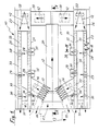
- Fig. 1 eine schematische Draufsicht einer Einrichtung zum Sortieren von Altglas, und zwar der wichtigsten Teile der für die Behandlung von Großmaterial bestimmten Sektion,
- Fig. 2 und 3 jeweils einen schematischen Schnitt entlang der Linie II - II bzw. III -III in Fig. 1 mit teilweiser Seitenansicht und in abweichendem Maßstab,
- Fig. 4 einen schematischen Schnitt entlang der Linie IV - IV in Fig. 3,
- Fig. 5 einen schematischen Schnitt entlang der Linie V - V in Fig. 1,
- Fig. 6 eine teilweise geschnittene Ansicht in Pfeilrichtung VI in Fig. 3,
- Fig. 7 eine schematische Seitenansicht einer Auswerfereinrichtung gemäß einem zweiten Ausführungsbeispiel,
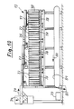
- Fig. 8 eine schematische Draufsicht eines Teils der Einrichtung zum Sortieren von Altglas, und zwar der zum Sortieren von Kleinmaterial geeigneten Sektion,
- Fig. 9 und 10 jeweils eine schematische, zum Teile geschnittene Ansicht der Sektion in Pfeilrichtung IX bzw. X in Fig. 8,
- Fig. 11, 12 und 13 jeweils einen schematischen Schnitt entlang der Linie XI - XI bzw. XII - XII bzw. XIII - XIII in Fig. 8.
- 1 is a schematic plan view of a device for sorting waste glass, namely the most important parts of the section intended for the treatment of large material,
- 2 and 3 are each a schematic section along the line II - II and III -III in Fig. 1 with a partial side view and on a different scale,
- 4 shows a schematic section along the line IV-IV in FIG. 3,
- 5 shows a schematic section along the line V - V in FIG. 1,
- 6 is a partially sectioned view in the direction of arrow VI in Fig. 3,
- 7 shows a schematic side view of an ejector device according to a second exemplary embodiment,
- 8 shows a schematic top view of part of the device for sorting waste glass, specifically the section suitable for sorting small material,
- 9 and 10 are each a schematic, partially sectioned view of the section in the direction of arrow IX and X in Fig. 8,
- 11, 12 and 13 each show a schematic section along the line XI-XI or XII-XII or XIII-XIII in FIG. 8.
In Fig. 1 - 6 ist von einer Einrichtung 10 zum Sortieren von Altglas, insbesondere Althohlglas, eine Sektion 11, die der Behandlung von Großmaterial 12 dient, und nur andeutungsweise eine Sektion 13 gezeigt, die der Behandlung von Kleinmaterial 14 dient und die im Detail in Fig. 8 - 13 dargestellt ist. Der besseren Übersicht wegen ist überwiegend des Großmaterial 12 und das Kleinmaterial 14 lediglich mit einem Pfeil symbolisch dargestellt, der zugleich die Transportrichtung vorgibt.1-6 of a
Der Einrichtung 10 wird mittels einer üblichen Fördereinrichtung, z.B. eines Förderbandes 15, in Pfeilrichtung (Fig. 2) mit dem Pfeil 16 angedeutetes Mischgut zugeführt. Dem Förderband 15 kann mindestens eine nicht weiter gezeigte Siebvorrichtung vorgelagert sein, über die z.B. Glasbruch od. dgl. vom Mischgut 16 abgesiebt wird. Bei der gezeigten spiegelbildlichen Gestaltung der Sektion 11 sind zwei zueinander parallele Förderbänder 15 vorhanden. Von diesen wird das Mischgut 16 jeweils einem anschließenden, in geeigneter Weise ausgebildeten Vorseparierer 17 zugeführt, der den zugeführten Massestrom in Großmaterial 12 einerseits und Kleinmaterial 14 andererseits separiert. Das Kleinmaterial 14 kann z.B. zunächst mittels Förderer einem Aufnahmebehälter 18 (Fig. 9) der Sektion 13 zugeführt werden oder es wird statt dessen direkt mittels Förderbändern 19 in die Sektion 13 eingeleitet.The
Nachfolgend wird zünachst die Behandlung des Großmaterials 12 in der Sektion 11 anhand von Fig. 1 - 7 erläutert.The treatment of the
Das mittels der Vorseparierer 17 aussortierte Großmaterial 12 gelangt über eine schräge Transportbahn 20 in Form z.B. eines Transportbandes auf eine das Großmaterial 12 verteilende Transportbahn 21. Diese erstreckt sich quer zur Transportbahn 20 und kann z.B. als Schwingfördereinrichtung ausgebildet sein. An jedes Ende der Transportbahn 21 sind zwei zueinander parallele und gleichartige Transportbahnen 22, 23 bzw. 24, 25 angeschlossen, die jeweils zueinander parallel verlaufen. Die Transportbahnen 22, 23 einerseits und 24, 25 andererseits sind jeweils gleichartig und dabei spiegelbildlich zueinander angeordnet. Sie sind jeweils als Schwingfördereinrichtungen ausgebildet. Weitere Details sind nachfolgend insbesondere anhand der Transportbahn 23 erläutert. Im Übergangsbereich zwischen jedem Ende der Transportbahn 21 und den quer daran anschließenden Transportbahnen 22, 23 bzw. 24, 25 befindet sich eine Verteilbahn 26 bzw. 27, die ebenfalls als Schwingfördereinrichtung ausgebildet ist und eine Aufteilung des ankommenden Großmaterialstromes 12 auf die Transportbahnen 22 und 23 bzw. 24 und 25 bewirkt. Dies ist schematisch durch auf diese gerichtete Pfeile der Verteilbahn 26 bzw. 27 angedeutet.The
Das auf der Transportbahn 23 in Transportrichtung vorwärts transportierte Großmaterial 12 ist entweder bereits vereinzelt mittels der Verteilbahn 26 zugeführt worden oder wird auf der Transportbahn 23 vereinzelt. Jedes Großmaterialstück 12 nimmt somit auf der Transportbahn 23 einen eigenen Platz ein und liegt dort so, daß sich quer zur Transportrichtung kein weiteres Teil daneben befindet, wobei sich in Transportrichtung die nächstfolgenden Großmaterialstücke 12 in Abstand davon befinden. Besteht das Großmaterialstück 12 aus einer Flasche, so befindet sich diese in liegender Position gemäß Fig. 3. Dort ist auf der Transportbahn 23 eine im Durchmesser kleinere Flasche als Großmaterialteil 12 und auf der Transportbahn 22 eine im Durchmesser größere Flasche als Großmaterialteil 12 gezeigt.The
Jede Transportbahn 22 - 25 ist so, wie schematisch nur für die Transportbahn 23 angedeutet ist, mit einzelnen in Transportrichtung in Abständen voneinander angeordneten Stationen 28, 29, 30 und 31 versehen. Das Großmaterial 12 wird vereinzelt auf den Transportbahnen 22 - 25 an den einzelnen Stationen 28, 29 und 30 vorbei bewegt wobei in jeder Station farbiges Material bestimmter Farbe aus dem Massestrom ausgesondert und entfernt wird. Beim gezeigten Ausführungsbeispiel sind der Aufbau und die Reihenfolge der Stationen 28 - 30 so gewählt, daß in der Station 28 aus dem Massestrom des Großmaterials 12 zunächst Braunglas aussortiert und entfernt wird, und zwar absolut sauber und farbecht, was durch entsprechenden Aufbau und entsprechende Einstellung der Station 28 bewirkt wird. Die Station 29 ist so beschaffen, daß in dieser aus dem verbleibenden und vorbeigeführten Massestrom des Großmaterials 12 weißes Glas ausgesondert und abgeführt wird, wobei auch hier aufgrund der Ausbildung und Einstellung der Station 29 eine große Farbechtheit erreichbar ist und gewährleistet ist, daß keinerlei Keramikteile dazwischen sind und je nach Einstellung sogar das weißeste Weiß augesondert werden kann. Mittels der Station 30 wird aus dem noch verbleibenden Massestrom des Großmaterials 12 grünes Glas und ferner Mischglas anderer Färbungen, das bisher in den Stationen 28 und 29 nicht ausgesondert und entfernt wurde, selektiert.Each transport track 22-25 is provided with
Hiernach verbleibt von dem Massestrom nach Passieren der Station 30 lediglich der Anteil übrig, der Unrat und dgl. lichtundurchlässige Teile enthält, die am Ende der Transportbahn 23 in der Station 31 anfallen und in eine dortige Aufnahmevorrichtung 32 abgegeben werden. An diese kann eine Transportbahn, z.B. ein Transportband, für den Abtransport angeschlossen sein.Thereafter, of the mass flow after passing through the
Die Station 28 ist somit derart aufgebaut und eingestellt, daß diese lediglich braunes Glas aus dem Massestrom des Großmaterials 12 selektiert, und dies absolut farbecht und sauber, wobei alle sonstigen Materialteile des Massestroms die Station 28 passieren. Die Station 29 ist so aufgebaut und eingestellt, daß mittels dieser im vorbeigeführten Massestrom enthaltenes Weißglas absolut sauber und farbecht ausgesondert wird, wobei alle sonstigen Bestandteile, auch Keramikpartikel, Unrat od. dgl., die im Massestrom mitgeführt werden, diese Station 29 passieren, ohne dort das ausgesonderte Weißglas zu verunreinigen. Die Station 30 ist derart gestaltet und eingestellt, daß darin aus dem restlichen Massestrom grünes Glas und Mischglas anderer Glassorten selektiert wird, wobei der danach verbleibende Rest des Massestroms, der überwiegend Unrat, sonstiges lichtundurchlässiges Material od. dgl. enthält, in der Station 31 von der dortigen Aufnahmevorrichtung 32 aufgenommen wird.The
Soll im Bereich der Station 30 nur Grünglas und nicht zusätzlich dazu noch sonstiges Mischglas selektiert werden, so ist die Station 30 derart aufgebaut und eingestellt, daß mittels dieser lediglich Grünglas selektiert wird und das verbleibende sonstige Mischglas im Massestrom verbleibt und dann mittels einer weiteren, nachgeschalteten und nicht gezeigten Station ausgesondert und dem Massestrom entnommen wird, woraufhin dann in der Station 31 lediglich Unrat und dgl. nicht lichtdurchlässiges Material gesammelt und abgeführt wird. Somit ist in einfacher Weise modulmäßig auch eine Umrüstung auf die Selektion reinen Grünglases möglich.If only green glass and not additionally any other mixed glass are to be selected in the area of
Die Transportbahnen 21 - 25 und die Verteilbahnen 26 und 27, entlang denen das Großmaterial 12 bewegt wird, sind jeweils als Schwingfördereinrichtungen ausgebildet. Dies ist in Fig. 1 schematisch dadurch angedeutet, daß jeweils unterhalb dieser Transportbahn gestrichelt ein Linearschwingförderer, der einen Schwingantrieb darstellt, gezeigt ist, der für alle Transportbahnen allgemein mit 33 bezeichnet ist.The transport tracks 21-25 and the distribution tracks 26 and 27, along which the
Jeder Station 28, 29 und 30 ist jeweils eine Aufnahmevorrichtung 34 bzw. 35 bzw. 36 zugeordnet, in der das jeweils aus dem Massestrom des Großmaterials 12 ausgesonderte Farbmaterial aufgenommen wird, wobei gleichartige Aufnahmevorrichtungen, die ausgesondertes Glasmaterial gleicher Farbe aufnehmen, über nicht weiter gezeigte Transporteinrichtungen, z.B. Transportbänder, miteinander verbunden sind, mittels denen das jeweils ausgesonderte Glasmaterial nicht weiter gezeigten Großbehältern zugeführt wird.Each
Der Vorseparierer 17 ist derart ausgebildet, daß dadurch solche Teile als Kleinmaterial 14 aussortiert werden, deren Durchmesser und/oder Kantenlänge kleiner als etwa 5 cm bis 7 cm, z.B. kleiner als 5,5 cm, bemessen ist.The pre-separator 17 is designed in such a way that parts are sorted out as
Details der jeweils als Schwingfördereinrichtungen ausgebildeten Transportbahnen 21 - 25 und Verteilbahnen 26 und 27 sind nachfolgend anhand von Fig. 4 - 6 verdeutlicht. Die Transportbahn 23 weist eine durch eine Winkelblech mit Boden 37 und Wandung 38 vorgegebene Rinne auf, die mit dem Boden 37 aus der Horizontalen heraus durch Anhebung der in Fig. 3 rechten Seite des Bodens 37 zumindest geringfügig schräg gestellt sein kann, wodurch sichergestellt wird, daß entlang der Transportbahn 23 transportiertes Großmaterial 12 möglichst in den Eckbereich zwischen dem Boden 37 und der Wandung 38 gezwungen wird und möglichst an beiden geführt ist und anliegt. Zumindest der Boden 37 - gewünschtenfalls außerdem auch die Wandung 38 - ist mit einem Belag 39 versehen, der zumindest im wesentlichen biegesteife Borsten 40, z.B. aus Kunststoff, trägt, die abstehen und eine Auflage für das Großmaterial 12 bilden. Die Borsten 40 der Beläge 39 sind in Richtung der jeweils gewünschten Transportrichtung schräg gestellt, wie insbesondere aus Fig. 5 und 6 ersichtlich ist. Die Transportrichtung ist dort durch den Pfeil 12 für das Großmaterial symbolisiert.Details of the transport tracks 21-25 and
Jede Station 28, 29 und 30 ist mit einer nachfolgend anhand von Fig. 3 - 6 nur für die Station 28 verdeutlichten Erkennungseinrichtung 41 und zugeordneten Auswerfereinrichtung 42 versehen, mittels denen aus dem Massestrom des Großmaterials 12 das jeweilige farbige Material selektierbar ist, d.h. in der Station 28 braunes Glas. Die Erkennungseinrichtung 41 der Station 28 ist mit einer nur schematisch angedeuten Farberkennungseinrichtung 43 und/oder Lichtschranke 44 versehen, die hier überlagert und zu einer Baueinheit vereinigt sind und deswegen nur symbolisch voneinander getrennt dargestellt und mit unterschiedlichen Bezugszeichen versehen sind. Die Farberkennungseinrichtung 43 und die Lichtschranke 44 ist jeweils mit mindestens einer Sendevorrichtung 43a bzw. 44a und einer zugeordneten Empfangsvorrichtung 43b bzw. 44b versehen. Die Sendevorrichtung 43a, 44a ist unterhalb der Transportbahn 23 und die Empfangsvorrichtung 43b, 44b mit Abstand oberhalb der Transportbahn 23 angeordnet, wobei Lage und Abstand so gewählt sind, daß die Empfangsvorrichtung 43b, 44b in diesem Bereich nicht stört. Die Transportbahn 23, und zwar sowohl der Boden 37 als auch der Belag 39, ist in dem Bodenbereich, der vom von der Sendevorrichtung 43a, 44a ausgehenden Erkennungsstrahl 45 getroffen wird, mit einer diesen ungehindert durchlassenden Öffnung 46 versehen, die z.B. als Langloch ausgebildet ist. Die Sendevorrichtung 43a, 44a und die zugeordnete Empfangsvorrichtung 43b, 44b sind gemeinsam in einer Fluchtlinie ausgerichtet, die durch den Verlauf des eingezeichneten Erkennungsstrahls 45 vorgegeben ist, wobei die Anordnung so getroffen ist, daß diese Fluchtlinie 45 gegenüber einer zur Ebene des Bodens 37 etwa rechtwinkligen Vertikalen in Fig.3 nach rechts hin um einen spitzen Winkel geneigt verläuft, der z.B. in der Größenordnung etwa von 30o liegt. Dabei schneidet der Erkennungsstrahl 45 die Ebene der Spitzen der Borsten 50 etwa in Höhe von einem Drittel der Gesamtbreite des Bodens 37, gemessen von der links befindlichen Ecke, an die die etwa vertikale Wandung 38 anschließt. Außerdem ist diese durch den Erkennungsstrahl 45 vorgegebene Fluchtlinie der Sendevorrichtung 43a, 44a und Empfangsvorrichtung 43b, 44b gegenüber der Vertikalen gegen die Transportrichtung gemäß Pfeil 12 in Fig. 6 um einen spitzen Winkel geneigt, der z.B. etwa in der Größenordnung von 15o liegt, wie Fig. 6 zeigt. Die Komponenten der Farberkennungseinrichtung 43 und Lichtschranke 44 sind somit schräg im Raum plaziert. Dadurch sind Verschmutzungen und etwaige Spiegelreflexionen von einem Teil, der die Station 28 passiert, vermieden. Das ausgehende Signal gemäß Erkennungsstrahl 45 geht durch das Großmaterialteil 12 hindurch, ohne daß sich Streulicht und ein dadurch etwa bedingtes Fehlsignal ergeben. Dies gilt für die Lichtschranke 44 ebenso wie für die Farberkennungseinrichtung 43. Beide sind in Fig. 3 - 6 so veranschaulicht, daß ihre jeweiligen Sendevorrichtungen 43a, 44a und Empfangsvorrichtungen 43b, 44b jeweils zu einer Baueinheit vereinigt sind. Bei einem anderen, nicht gezeigten und besonders vorteilhaften Ausführungsbeispiel sind die Sendevorrichtungen und die Empfangsvorrichtungen der Farberkennungseinrichtung 43 und der Lichtschranke 44 andererseits jeweils selbständige Teile und separat plaziert. Dabei ist es von besonderem Vorteil, wenn die jeweilige Sendevorrichtung 43a und Empfangsvorrichtung 43b der Farberkennungseinrichtung 43 separat und dabei spiegelbildlich zur Sendevorrichtung 44a und Empfangsvorrichtung 44b der Lichtschranke 44 angeordnet sind. Dann kreuzt der Erkennungsstrahl 45 der Farberkennungseinrichtung 43 einen demgegenüber spiegelbildlichen Erkennungsstrahl der Lichtschranke 44 im Bereich der Ebene der Spitzen der Borsten 40 und dabei im Bereich der Öffnung 46. Bei dieser spiegelbildlichen Anordnung der Komponenten der Farberkennungseinrichtung 43 einerseits und Lichtschranke 44 andererseits ist jeglicher Gefahr einer etwaigen wechselseitigen Beeinträchtigung vorgebeugt.Each
Die Farberkennungseinrichtung 43 ist hinsichtlich ihrer beschriebenen Komponenten nur schematisch angedeutet. Sie weist Sensoren auf und ist in der Station 28 so eingestellt, daß die Farberkennungseinrichtung 43 aus dem Massestrom des vorbeigeführten Großmaterials 12 braunes Glas erkennt und selektiert, und zwar mit großer Farbechtheit und derart sauber, wie derartiges Braunglas für das Recycling von der Industrie benötigt wird. Die Lichtschranke 44 arbeitet z.B. im Infrarotbereich. Sie kann Glasfaserlichtleiter aufweisen. Auch diese ist in der Station 28 auf die Selektion von braunem Glas eingestellt.The
In der Weise, wie die Station 28 mit einer auf die Selektion von braunem Glas eingerichteten Erkennungseinrichtung 41 versehen ist, sind auch die übrigen Stationen 29 und 30 mit entsprechenden Erkennungseinrichtungen, bestehend aus einer Farberkennungseinrichtung und einer zugeordneten Lichtschranke, ausgerüstet, wobei diese- der Bestimmung der Stationen entsprechend-so aufgebaut und eingestellt sind, daß in der Station 29 weißes Glas farbecht und mit großer Genauigkeit aus dem vorbeigeführten Massestrom selektiert wird und in gleicher Weise in der Station 30 aus dem restlichen Massestrom grünes Glas sowie sonstiges lichtdurchlässiges Glas anderer Farben und Sorten selektiert wird.In the way in which the
Nachfolgend ist anhand von Fig. 3 und 4 die Auswerfereinrichtung 42 der Station 28 näher erläutert. Die Auswerfereinrichtung 42 weist einzelne an einem Träger 47 in z.B. gleichen Abständen voneinander gehaltene und davon abstehende Auswerferglieder 48 auf, die etwa fingerartig abstreben und daher nachfolgend auch als Auswerferfinger bezeichnet sind. Der Träger 47 besteht hier aus einer senkrechten,die radial gerichteten Auswerferfinger 48 tragenden Kreisscheibe und ist um eine zur Transportrichtung gemäß Pfeil 12 z.B. im wesentlichen parallele Rotationsachse 49 mittels eines Antriebes 50 rotierend angetrieben, wobei der Antrieb absatzweise und dabei immer in einer Richtung erfolgt, die hier gemäß Pfeil 51 im Gegenuhrzeigersinn weist. Die Auswerferfinger 48 werden bei Betätigung des Trägers 47 durch den Antrieb 50 in Pfeilrichtung 51 quer zur Transportbahn 23 bewegt, wobei das jeweilige sich augenblicklich in der Station 28 befindliche und von der Erkennungseinrichtung 41 als abzuwerfendes Materialteil 12 erkannte Teil quer zur Transportrichtung gemäß Pfeil 12 von der Transportbahn 23 abgeworfen wird. Wie gezeigt, lagert jeweils ein Auswerferfinger 48 in seiner abwurfbereiten Ausgangsstellung innerhalb einer Öffnung 52 der seitlich hochstehenden Wandung 38. Die Breite jedes Auswerferfingers 48 und diejenige der Öffnung 52 sind so aufeinander abgestimmt, daß ein in der Öffnung 52 in seiner abwurfbereiten Ausgangstellung lagernder Auswerferfinger 48 die Öffnung 52 zumindest annähernd ausfüllt und dort ein die Wandung 38 praktisch komplettierendes Wandungsteil bildet, so daß daran vorbeibewegtes Großmaterial 12 nicht daran hängen bleiben kann. Jeder Auswerferfinger 48 weist eine dem Querschnitt der Wandung 38 etwa entsprechende Dicke und eine im Vergleich zur Dicke vorzugsweise größere Breite auf, wie Fig. 4 zeigt. Innerhalb der Ebene der Wandung 38 gesehen hat jeder Auswerferfinger 48 somit etwa Plattenform. Die Breite kann auch größer als dargestellt gewählt werden. Es versteht sich, daß die Auswerfereinrichtung 42 der Station 28 und die Komponenten der Erkennungseinrichtung 41, insbesondere Farberkennungseinrichtung 43 und Lichtschranke 44, dieser Station räumlich so angeordnet sind, daß sie sich gegenseitig nicht behindern, insbesondere die Auswerfereinrichtung 42 nicht die Empfangsvorrichtungen 43b und 44b berührt.The
An der in Fig. 3 und 4 rechten Seite der Transportbahn 23 ist eine die Transportbahn 23 dort begrenzende Wandung 43 vorgesehen, die zusammen mit dem Boden 37 einen Winkel größer 90o einschließt und somit von unten nach oben und außen schräggerichtet ist. In dieser Wandung 53 ist im Bereich jeder Station 28, 29 und 30 eine Abgabeöffnung 54 enthalten, deren Größe so groß wie das größtmögliche separierte und abzuwerfende Großmaterialteil 12 gewählt ist. Da davon auszugehen ist, daß als Großmaterial 12 auch liegende und nicht zerbrochene Flaschen entlanggefördert werden, ist die in Transportrichtung gemessene Größe der Abgabeöffnung 54 größer als das größtmögliche Flaschenmaß, das zu erwarten ist, gewählt.On the right in FIGS. 3 and 4 of the
Beim gezeigten Ausführungsbeispiel der Auswerfereinrichtung 42 werden die Auswerferfinger 48 entlang einer kreisbogenförmigen Bahn absatzweise und derart bewegt, daß ein in der Öffnung 52 lagernder Auswerferfinger 48 das jeweils abzuwerfende Großmaterialteil 12 quer zur Transportrichtung abwirft und zugleich ein nächstfolgender Auswerferfinger dabei in der gleichen Richtung gemäß Pfeil 51 in seine abwurfbereite Ausgangsstellung in die Öffnung 52 bewegt wird, wie Fig. 4 zeigt.In the exemplary embodiment of the
Bei einem anderen, nicht gezeigten Ausführungsbeispiel werden die Auswerferfinger mittels eines Trägers entlang einer geraden Bahn oder einer von einer Kreisbogenbahn abweichenden anderen bogenförmigen Bahn in gleicher Weise absatzweise bewegt. Die Bahn kann z.B. einem Ellipsenabschnitt, einem Parabelabschnitt oder einem anderen Kurvenabschnitt folgend gewählt sein. In Fig. 7 ist schematisch ein abgewandeltes Ausführungsbeispiel einer Auswerfereinrichtung 42′ gezeigt, bei der der Träger 47′ als zweifach umgelenkte Kette, Riemen, Band od.dgl. Endloselement ausgebildet ist, an dem die abstehenden einzelnen Auswerferfinger 48′ gehalten sind. Der so gestaltete Träger 47′ in Form einer Kette ist an beiden Umlenkenden über jeweils ein Kettenrad 55, 56 geführt, von denen das letztere mittels eines Antriebes 50′ in Pfeilrichtung 51′ absatzweise dann angetrieben wird, wenn die zugeordnete Erkennungseinrichtung einen Antriebsimpuls auf den Antrieb 50′ gibt.In another embodiment, not shown, the ejector fingers are in the same way by means of a carrier along a straight path or another arc-shaped path deviating from a circular arc path moved in batches. The path can be chosen, for example, following an ellipse section, a parabola section or another curve section. In Fig. 7, a modified embodiment of an ejector 42 'is shown schematically, in which the carrier 47' or the like as a double-deflected chain, belt, band. Endless element is formed on which the projecting individual ejector fingers 48 'are held. The carrier 47 'designed in this way in the form of a chain is guided at both deflecting ends via a
Nachfolgend ist anhand von Fig. 8 - 13 die andere Sektion 13 der Einrichtung 10 erläutert, mittels der Kleinmaterial 14 selektiert wird.The
Das durch Pfeil 14 symbolisierte Kleinmaterial wird zunächst z.B. mittels Förderbändern 19 zugeführt und über eine als Schwingfördereinrichtung ausgebildete Verteilbahn 57 umgelenkt und einer linearen Schwingfördereinrichtung 58 zugeführt. An eine Längsseite der linearen Schwingfördereinrichtung 58 schließt sich eine Vielzahl einzelner schräg nach unten gerichteter Schwingfördereinrichtungen 59 an, die einzelne Förderrinnen 60 aufweisen, wobei mehrere schräge Schwingfördereinrichtungen 59 jeweils zu einer Platte zusammengefaßt sind, die jeweils z.B. sieben Förderrinnen 60 aufweist. Das herangeführte Kleinmaterial 14 wird mittels der linearen Schwingfördereinrichtung 58 in Längsrichtung gefördert und vereinzelt und - wie durch rechtwinklig abknickende Pfeile 61 angedeutet ist - ausgehend von dort auf die einzelnen angeschlossenen,schräg nach unten gerichteten Schwingfördereinrichtungen 59 mit einzelnen Förderrinnen 60 verteilt und dort bis zum unteren Ende jeder einzelnen Förderrinne 60 transportiert. Dabei wird das Kleinmaterial 14 auf diesem Weg ebenfalls vereinzelt. Jede schräg nach unten gerichtete Förderrinne 60 bildet eine Transportbahn, die in gleicher Weise wie die Transportbahnen 21 - 25 und Verteilbahnen 26 und 27 auf dem Boden 37 und außerdem an der etwa winklig an einer Seite angrenzenden Wandung 38 mit einem Belag 39 mit abstehenden Borsten 40 versehen sind, wie lediglich in Fig. 11 - 13 und in Fig. 9 rechts angedeutet ist. Fig. 11 zeigt, daß die Borsten 40 des Belages 39 in Fig. 11 oben schräg in Transportrichtung gemäß Pfeil 61 gerichtet sind, so daß das Kleinmaterial 14 in Pfeilrichtung 61 auf die Förderrinnen 60 geleitet wird, und daß der restliche Teil der Borsten 40 in Richtung des Längsverlaufs der linearen Schwingfördereinrichtung 58 gerichtet ist, so daß diese Borsten 40 herangeführtes Kleinmaterial 14 in Längsrichtung weitertransportieren. Dies veranschaulicht Fig. 12, wo diese längsgerichtete Transportrichtung mit Pfeil 14 für das Kleinmaterial gekennzeichnet ist.The small material symbolized by
Fig. 9 zeigt rechts eine einzige Förderrinne 60, die entsprechend dem Schnitt in Fig. 13 im Bereich des Bodens 37 und der Wandung 38 jeweils mit einem erläuterten Belag 39 versehen ist. Am unteren Ende dieser Förderrinne ist eine Erkennungseinrichtung 41 für diese Förderrinne 60 vorgesehen, die hier lediglich aus einer Lichtschranke 44 besteht, die eine Sendevorrichtung 44a und eine Empfangsvorrichtung 44b aufweist. Die Sendevorrichtung 44a und Empfangsvorrichtung 44b der Lichtschranke 44 ist in gleicher Weise wie aus Fig. 6 hervorgeht in Transportrichtung des Kleinmaterials 14 gegenüber der zum Boden 37 rechtwinklig verlaufenden Linie in Transportrichtung um einen spitzen Winkel schräggestellt, der z.B. in der Größenordnung von 15o liegen kann. Der Erkennungsstrahl 45, der von der Sendevorrichtung 44a ausgeht und auf die Empfangsvorrichtung 44b gerichtet ist, steht somit nicht rechtwinklig zum Boden 37,sondern verläuft demgegenüber in Transportrichtung schräg. Bedarfsweise sind am unteren Ende jeder Förderrinne 60 mehrere derartige Lichtschranken 44 quer zur Transportrichtung nebeneinander plaziert, die somit praktisch einen Lichtschrankenvorhang bilden.FIG. 9 shows on the right a
In Abstand von der Lichtschranke 44 und dem unteren Ende jeder Förderrinne 60 ist je Förderrinne 60 eine um eine etwa horizontale Achse 62 schwenkbar gehaltene Abweisklappe 63 angeordnet, die von einem Antrieb in Form eines Pneumatikzylinders 64 in Abhängigkeit eines von der Erkennungseinrichtung 41 gelieferten Impulses betätigbar ist. Die Abweisklappe 63 mitsamt ihrem zugeordneten Pneumatikzylinder 64 und die Erkennungseinrichtung 41 ist mittels einer Halteeinrichtung 65 gehalten und höhenverstellbar. In der in Fig. 9 mit durchgezogenen Linien gezeigten, etwa lotrechten Stellung befindet sich die Abweisklappe 63 in ihrer Ausgangsstellung, die die Abweisklappe 63 dann einnimmt und beibehält, wenn kein den Pneumatikzylinder 64 beaufschlagender Impuls von der Erkennungseinrichtung 41 kommt, d. h. wenn die Lichtschranke 44 nicht unterbrochen wird. Wird dagegen die Lichtschranke 44 unterbrochen, so wird von dieser der Pneumatikzylinder 64 angesteuert, der die Abweisklappe 63 in Pfeilrichtung 66 um die Achse 62 im Gegenuhrzeigersinn nach vorn in die gestrichelt angedeutete Stellung schwenkt. In dieser Abweisstellung ist die Abweisklappe 63 in der Lage, am Ende der Förderrinne 60 befindliches Kleinmaterial 14, das aus Unrat od. dgl. lichtundurchlässigem Material besteht und die Unterbrechung der Lichtschranke 44 hervorgerufen hat, in Richtung des gestrichelten Pfeiles 67 abzuweisen und in ein zugeordnetes darunter befindliches Aufnahmebehältnis 68 zu leiten, in das dieses Material hineinfällt. Das Aufnahmebehältnis 68 kann mehreren Förderrinen 60 gemeinsam sein oder über sämtliche Förderrinen 60 verlaufen und mit einer Transportbahn 69, z. B. einem Transportband, in Verbindung stehen, über die das so selektierte lichtundurchlässige Material in Pfeilrichtung 70 abtransportiert wird. Sofort nach Schwenken der Abweisklappe 63 in die gestrichelte Abweisstellung wird die Abweisklappe 63 mittels des Pneumatikzylinders 64 wieder in die vertikale Ausgangsstellung zurückgestellt, in der die Abweisklappe 63 wiederum solange verbleibt, bis bei die Lichtschranke 44 durchbrechendem lichtundurchlässigem Material erneut ein Betätigungsimpuls vom Pneumatikzylinder 64 ausgeübt wird. In der vertikalen Ausgangsstellung der Abweisklappe 63 ist diese entweder unwirksam oder zumindest nur so wirksam, daß am unteren Ende der Förderrinne 60 abgegebenes Kleinmaterial 14 in Pfeilrichtung 71 entweder zunächst in ein Aufnahmebehältnis 72 oder gleich auf eine Transportbahn 73, z. B. in Form eines Transportbandes, abgegeben wird. Das Aufnahmebehältnis 72 und insbesondere die Transportbahn 73 erstreckt sich entlang den unteren Enden aller schrägen Förderrinnen 60 und ist diesen gemeinsam, so daß die Transportbahn 73 das gesamte Kleinmaterial der Förderrinnen 60 aufnimmt, das bei der Selektion und Abfuhr von Unrat od. dgl. lichtundurchlässigen Teilen übriggeblieben ist. Hierbei handelt es sich um davon befreites Mischglas 74, auch durch entsprechenden Pfeil gekennzeichnet.At a distance from the
Das Mischglas 74 wird über die schräg von unten nach oben führende Transportbahn 73 abtransportiert und über eine Verteilbahn 75 einer linearen Schwingfördereinrichtung 76 zugeführt. Die Verteilbahn 75 und lineare Schwingfördereinrichtung 76 ist analog denjenigen 57 bzw. 58 aufgebaut. An der in Fig. 8 unteren Längsseite der linearen Schwingfördereinrichtung 76 schließt sich eine Vielzahl einzelner schräg nach unten gerichteter Schwingfördereinrichtungen 77 an, die analog derjenigen 59 ausgebildet sind und ebenfalls einzelne Förderrinnen 78 aufweisen, von denen jede so wie jede Förderrinne 60 am unteren Ende jeweils eine Erkennungseinrichtung 41 in Form einer Lichtschranke 44 mit Sendevorrichtung 44a und Empfangsvorrichtung 44b sowie eine Abweisklappe 63 mit zugeordnetem Pneumatikzylinder 64 an einer Halteeinrichtung 65 aufweist. Am Ende jeder Förderrinne 78 wird das transportierte und vereinzelte Mischglas 74 nach Weißglas 79 einerseits und einer Mischung 80 aus Grünglas und Braunglas andererseits selektiert, wobei für beide je weils zugeordnete Aufnahmebehältnisse 81 bzw. 82 vorgesehen sein können oder statt dessen das Weißglas 79 bzw. die Mischung 80 aus Grün- und Braunglas direkt auf zugeordnete Transportbahnen 83 bzw. 84, z. B. Transportbänder, geleitet wird, über die die Ableitung erfolgt.The mixing
Wie ersichtlich ist, wird somit mittels der Einrichtung 10 die Selektion des Großmaterials 12 im Bereich der jeweiligen Erkennungseinrichtung 41 durch dortige Überlagerung von jeweiligen Farberkennungseinrichtungen 43 einerseits und Lichtschranken 44 andererseits vorgenommen. Dabei wird aus dem Großmaterial 12 zunächst farbiges Material, insbesondere in der Reihenfolge der Farben braun, weiß und grün, in den Stationen 28 bzw. 29 bzw. 30 selektiert und erst dann, und zwar am Schluß, als übrigbleibender Teil des Massestroms des Großmaterials 12 verbleibender Unrat und dgl. nicht lichtdurchlässige Teile im Bereich der Station 31 und dortigen Aufnahmevorrichtung 32 gesammelt bzw. mittels Transportband gleich abtransportiert. Auf diese Weise ist erreicht, daß zunächst in der Station 28 absolut sauber und farbecht aus dem Massestrom des Großmaterials 12 braunes Glas ausgesondert und abtransportiert wird, und zwar in der Farbechtheit und Qualität, wie sie von der Industrie benötigt wird. Ferner ist auf diese Weise sichergestellt, daß in der nachfolgenden Station 29 aus dem verbleibenden vorbeigeführten Massestrom sodann weißes Glas mit hoher Farbechtheit selektiert wird, das u. a. auch frei von Keramik ist. Durch entsprechende Einstellung der einzelnen Erkennungseinrichtungen 41 in den Station 28 und 29 läßt sich die Farbreinheit braun bzw. weiß den jeweiligen Vorgaben anpassen, z. B. so, daß das Braunspektrum für auszusortierendes braunes Glas noch schmaler und das Weißspektrum ebenfalls entsprechend schmaler bis hin zum weißesten Weiß gewählt werden kann. In der Station 30 wird mittels der dortigen Erkennungseinrichtung 41 aus dem verbleibenden Massestrom Glas mit grüner Farbe sowie Mischglas sonstiger Farben, die bisher nicht aussortiert wurden, ausgesondert. Bedarfsweise kann in dieser Station auch eine Aussonderung von reinem Grünglas erfolgen und die Aussonderung von Mischglas anderer Glassorten und Farben in einer nachgeschalteten weiteren Station geschehen, sofern dies gefordert wird. Am Ende bleibt Unrat und dgl. lichtundurchlässiges Material übrig. Durch die Anordnung und Ausbildung der einzelnen Transportbahnen 21 - 25 sowie Verteilbahnen 26 und 27 und durch die spezielle Ausbildung des Belages 39 mit Borsten 40 werden große Fördergeschwindigkeiten und somit große Massendurchsätze mit zuverlässiger Vereinzelung der einzelnen Materialteile erreicht. Diese liegen ruhig auf den Borsten 40 auf und werden hinsichtlich ihrer Bewegung gedämpft. Es ergeben sich somit eine große Laufruhe und Geräuscharmut ohne Lärmbelästigung der Umgebung, und dies bei außerordentlich hohen Fördergeschwindigkeiten. Dadurch sind Durchsätze in der Größenordnung mehrerer Tonnen pro Stunde erzielbar. Von Vorteil ist ferner, daß mittels der Erkennungseinrichtungen 41, und zwar sowohl beim Großmaterial 12 als auch beim Kleinmaterial 14, mit hoher Genauigkeit und Zuverlässigkeit Unrat und sonstige nicht lichtdurchlässige Teile, vor allem auch keramische Stoffe und sonstige, für neu zu fertigende Hohlgläser gefährliche Anteile, separiert werden können. Die Erkennungseinrichtungen 41 sind so gestaltet, daß deren Analog- oder Digitalausgang jeweils gut auswertbare Signale in Bezug auf die Art des zu sortierenden Materials liefern, so daß also immer zuverlässige Ausgangssignale erzeugt werden. Da die Auswerfereinrichtung 42 mit den Auswerferfingern 48 je Station 28, 29 und 30 so arbeitet, daß bei der Selektion je Station 28, 29 und 30 der Auswurf in einer Richtung, und zwar Antriebsrichtung gemäß Pfeil 51 bzw. 51′ erfolgt, wobei die Bewegung des Auswerferfingers 48 in ihre auswurfbereite Ausgangsstellung in der gleichen Richtung gemäß Pfeil 51 bzw. 51′ erfolgt, geschieht keine dazu gegensinnige Rückstellbewegung in die Ausgangsstellung, die sonst den Weitertransport des Großmaterials 12 in Transportrichtung verzögern oder behindern könnte. Vielmehr wird jeder Aus werferfinger 48 außerhalb des Bereichs der jeweiligen Transportbahn 23 in seine auswurfbereite Ausgangsstellung ge bracht. Da sich jeder Auswerferfinger 48 in dieser Stellung etwa deckungsgleich mit der Wandung 38 und somit nahe des jeweiligen, die Station 28, 29 oder 30 passierenden Großmaterials 12 befindet, ist der im Falle eines zu erfolgenden Auswurfes zu durchlaufende Auswurfweg für den Auswerferfinger 48 außerordentlich klein. Dies ermöglicht kurze Taktzeiten für das absatzweise Bewegen der Auswerfereinrichtung 42. Wird jeder Auswerferfinger 48, betrachtet in Transportrichtung, etwa plattenförmig und somit mit wesentlicher Breite ausgebildet, so wird die Sicherheit noch erhöht, selbst in Transportrichtung kleinste Großmaterialstücke 12 dann mittels dieses Auswerferfingers 48 quer zur Transportrichtung durch die Abgabeöffnung 54 hindurch auszuwerfen, wenn beim Passieren der Erkennungseinrichtung 41 von dieser auf den Antrieb 50 der Auswerfereinrichtung 42 ein entsprechender Impuls geleitet wird und dadurch die Auswerfereinrichtung um einen Schritt in Antriebsrichtung 51 fortgeschaltet wird. Dadurch, daß die einzelnen Komponenten der Farberkennungseinrichtung 43 und Lichtschranke 44 jeder einzelnen, je Station 28, 29 und 30 vorhandenen Erkennungseinrichtung 41 in beschriebener Weise schräg im Raum angeordnet sind, werden etwaige Streustrahlen und dadurch bedingte Fehlsignale vermieden. Vielmehr ist gewährleistet, daß die Erkennungseinrichtung 41 mit großer Genauigkeit exakt jedes einzelne Materialteil erfaßt und über die zugeordnete Auswerfereinrichtung 42 aussortiert, das je Station 28, 29 und 30 und Einstellung tatsächlich erfaßt werden soll.As can be seen, the
Bei der Selektion des Kleinmaterials 14 mittels der Sektion 13 wird stufenweise zunächst nach Mischglas 74 einerseits und Unrat und dgl. lichtundurchlässigem Material andererseits selektiert. In einer nächsten Stufe wird dann das Mischglas nach Weißglas 79 einerseits und einer Mischung 80 aus Grün- und Braunglas sowie sonstige Farben aufweisendem Glas andererseits selektiert. Sofern dies gewünscht wird, kann in einer weiteren, entsprechend ausgebildeten Stufe eine weitere Selektion der Mischung 80 nach Braunglas einerseits und Grünglas und sonstige Farben enthaltendes Glas anderer seits erfolgen. Von besonderem Vorteil ist dabei, daß man das jweilige Kleinmaterial 14 am Ende der einzelnen schräg nach unten gerichteten Förderrinnen 60 und 78 mittels dortiger Lichtschranken 44, zumindest einer je Förderrinne 60 bzw. 78, in dem Augenblick erfaßt, in dem das Kleinmaterial 14 noch zumindest teilweise auf der Transportbahn der Förderrinne 60 bzw. 78 aufliegt und mit einem vom Erkennungsstrahl 45 quer passierten Teil bereits davon frei absteht, so daß dieser Materialteil vom Erkennungsstrahl 45 passiert werden kann. Dadurch ist eine große Genauigkeit bei der Erkennung und Selektion des Kleinmaterials 14 gewährleistet, so daß mit außerordentlich großer Genauigkeit letztlich eine Selektion von Weißglas 79 einerseits und einer Mischung 80, bestehend aus Grünglas, Braunglas und andere Farben enthaltendem Glas, andererseits ermöglicht ist und etwaiger Unrat od. dgl. lichtundurchlässige Teile davon von vornherein schon in der ersten Selektionsstufe abgespalten werden kann.When the
Die Einrichtung 10 ist hinsichtlich ihrer einzelnen Komponeten modular aufgebaut, wodurch Durchsatzmengen und die Anlagenkonzeption jeweils nach Wunsch variabel zusammengestellt werden können.The
Claims (54)
Applications Claiming Priority (2)
| Application Number | Priority Date | Filing Date | Title |
|---|---|---|---|
| DE19883817026 DE3817026A1 (en) | 1988-05-19 | 1988-05-19 | METHOD AND DEVICE FOR SORTING OLD GLASS |
| DE3817026 | 1988-05-19 |
Publications (2)
| Publication Number | Publication Date |
|---|---|
| EP0342389A2 true EP0342389A2 (en) | 1989-11-23 |
| EP0342389A3 EP0342389A3 (en) | 1992-08-12 |
Family
ID=6354673
Family Applications (1)
| Application Number | Title | Priority Date | Filing Date |
|---|---|---|---|
| EP19890107361 Withdrawn EP0342389A3 (en) | 1988-05-19 | 1989-04-24 | Method and device for sorting old glass |
Country Status (2)
| Country | Link |
|---|---|
| EP (1) | EP0342389A3 (en) |
| DE (1) | DE3817026A1 (en) |
Cited By (5)
| Publication number | Priority date | Publication date | Assignee | Title |
|---|---|---|---|---|
| US5333797A (en) * | 1992-04-03 | 1994-08-02 | Becker John C | Commingled recyclables recovery and recycling process and related apparatuses |
| US5333739A (en) * | 1992-03-27 | 1994-08-02 | Bodenseewerk Geratechnik GmbH | Method and apparatus for sorting bulk material |
| US5344025A (en) * | 1991-04-24 | 1994-09-06 | Griffin & Company | Commingled waste separation apparatus and methods |
| GB2283812A (en) * | 1993-11-10 | 1995-05-17 | Kanetsu Engineering Co Ltd | Automatic colour sorting apparatus and method for sorting and recovering cullets |
| NL1006555C2 (en) * | 1997-07-11 | 1999-01-12 | Con Weigh Beheer B V | Device intended for the inspection, sorting and / or dosing of chaotically ordered objects. |
Families Citing this family (3)
| Publication number | Priority date | Publication date | Assignee | Title |
|---|---|---|---|---|
| DE9106292U1 (en) * | 1991-05-22 | 1991-07-18 | Glasrecycling Leeseringen Gmbh & Co. Kg, 3071 Estorf, De | |
| DE4200226A1 (en) * | 1992-01-08 | 1993-07-15 | Josef Kamps | Machine for identifying colour differences of single fractions of bulk material - distributes bulk material simultaneously in to fractions and includes storage container for bulk material with dosing and distribution unit and plate conveyor. |
| DE9413671U1 (en) * | 1994-08-25 | 1994-11-24 | Zmb Maschinenbau Gmbh | Sorting system for color sorting of glass, preferably waste glass |
Citations (5)
| Publication number | Priority date | Publication date | Assignee | Title |
|---|---|---|---|---|
| DE3119329A1 (en) * | 1981-05-15 | 1982-11-25 | Gerresheimer Glas AG, 4000 Düsseldorf | Device for the colour-sorting of used glass containers |
| DE3207447A1 (en) * | 1982-03-02 | 1983-09-29 | Fraunhofer-Gesellschaft zur Förderung der angewandten Forschung e.V., 8000 München | Method and device for detecting and separating glass fragments in accordance with optical properties |
| FR2544856A1 (en) * | 1983-04-25 | 1984-10-26 | Oreal | Method for inspecting the thickness of the walls of glass receptacles and corresponding device |
| DE3346129A1 (en) * | 1983-12-21 | 1985-07-11 | Fa. Hermann Heye, 3063 Obernkirchen | Method and device for sorting refuse containing used glass |
| DE3445428A1 (en) * | 1984-12-13 | 1986-06-19 | MAB Marlis Kellermann, 7521 Dettenheim | Glass sorting system |
Family Cites Families (1)
| Publication number | Priority date | Publication date | Assignee | Title |
|---|---|---|---|---|
| US3980180A (en) * | 1974-11-20 | 1976-09-14 | Jamieson John A | Transmissive article sorting apparatus |
-
1988
- 1988-05-19 DE DE19883817026 patent/DE3817026A1/en not_active Withdrawn
-
1989
- 1989-04-24 EP EP19890107361 patent/EP0342389A3/en not_active Withdrawn
Patent Citations (5)
| Publication number | Priority date | Publication date | Assignee | Title |
|---|---|---|---|---|
| DE3119329A1 (en) * | 1981-05-15 | 1982-11-25 | Gerresheimer Glas AG, 4000 Düsseldorf | Device for the colour-sorting of used glass containers |
| DE3207447A1 (en) * | 1982-03-02 | 1983-09-29 | Fraunhofer-Gesellschaft zur Förderung der angewandten Forschung e.V., 8000 München | Method and device for detecting and separating glass fragments in accordance with optical properties |
| FR2544856A1 (en) * | 1983-04-25 | 1984-10-26 | Oreal | Method for inspecting the thickness of the walls of glass receptacles and corresponding device |
| DE3346129A1 (en) * | 1983-12-21 | 1985-07-11 | Fa. Hermann Heye, 3063 Obernkirchen | Method and device for sorting refuse containing used glass |
| DE3445428A1 (en) * | 1984-12-13 | 1986-06-19 | MAB Marlis Kellermann, 7521 Dettenheim | Glass sorting system |
Cited By (6)
| Publication number | Priority date | Publication date | Assignee | Title |
|---|---|---|---|---|
| US5344025A (en) * | 1991-04-24 | 1994-09-06 | Griffin & Company | Commingled waste separation apparatus and methods |
| US5333739A (en) * | 1992-03-27 | 1994-08-02 | Bodenseewerk Geratechnik GmbH | Method and apparatus for sorting bulk material |
| US5333797A (en) * | 1992-04-03 | 1994-08-02 | Becker John C | Commingled recyclables recovery and recycling process and related apparatuses |
| GB2283812A (en) * | 1993-11-10 | 1995-05-17 | Kanetsu Engineering Co Ltd | Automatic colour sorting apparatus and method for sorting and recovering cullets |
| NL1006555C2 (en) * | 1997-07-11 | 1999-01-12 | Con Weigh Beheer B V | Device intended for the inspection, sorting and / or dosing of chaotically ordered objects. |
| WO1999002279A1 (en) * | 1997-07-11 | 1999-01-21 | Con-Weigh Beheer B.V. | Device for inspecting, sorting and/or dosing of chaotically arranged objects |
Also Published As
| Publication number | Publication date |
|---|---|
| EP0342389A3 (en) | 1992-08-12 |
| DE3817026A1 (en) | 1989-11-23 |
Similar Documents
| Publication | Publication Date | Title |
|---|---|---|
| EP0669171B1 (en) | Device for sorting refuse | |
| EP0666115A2 (en) | Method for sorting bulk particles and device for that purpose | |
| EP0982083B1 (en) | Linear sorting apparatus | |
| EP0029614B1 (en) | Device for the lateral deviation of articles from a first conveying device to a second one | |
| DE1965351C3 (en) | Arrangement for sorting objects randomly distributed on a conveyor belt according to their reflective properties | |
| DE3612076C2 (en) | ||
| DE2541813A1 (en) | FACILITY FOR ARRANGING A NUMBER OF DISORDERED CONTAINERS INTO A SINGLE MOVING ROW | |
| CH643160A5 (en) | DEVICE FOR CLASSIFYING PARTICLES WITH DIFFERENT COLORING. | |
| EP0342389A2 (en) | Method and device for sorting old glass | |
| EP0328126A2 (en) | Method and device for sorting spent glass | |
| DE3614400C1 (en) | Method and device for controlling a color sorting machine | |
| DE102009033325A1 (en) | Delivery unit transferring bottle caps from sorting equipment to capping machine, includes exit section with pneumatic and vibratory system leading row of caps to process conveyor | |
| DE3828067C2 (en) | ||
| DE19646753C2 (en) | Device for quality and / or size sorting of small-sized products | |
| DE19545240A1 (en) | Sorting machine achieving more precise recognition and separation of e.g. mixed plastics fractions | |
| WO1997019873A1 (en) | Device for selecting one or more rotationally symmetrical containers from a stream of rotationally symmetrical containers conveyed under pressure from behind, and cylinder with controlled plunger | |
| DE3914360C2 (en) | ||
| DE10123304A1 (en) | Line for automatic sorting of waste includes station with compressed air jets for ballistic separation of film from heavier particles | |
| AT395545B (en) | SORTING DEVICE | |
| AT402165B (en) | Process and apparatus for sorting waste materials | |
| DE4302736C2 (en) | Method and device for sorting plastic containers | |
| DE3423236C1 (en) | Device for monitoring shrimp peeling machines | |
| DE4438676C1 (en) | Pre=sorting and transport device for recycled glass | |
| AT400413B (en) | Apparatus for sorting waste materials | |
| DE4344832A1 (en) | Method and device for automatic color sorting for sorting and recovering broken glass |
Legal Events
| Date | Code | Title | Description |
|---|---|---|---|
| PUAI | Public reference made under article 153(3) epc to a published international application that has entered the european phase |
Free format text: ORIGINAL CODE: 0009012 |
|
| AK | Designated contracting states |
Kind code of ref document: A2 Designated state(s): AT BE CH DE ES FR GB GR IT LI LU NL SE |
|
| PUAL | Search report despatched |
Free format text: ORIGINAL CODE: 0009013 |
|
| AK | Designated contracting states |
Kind code of ref document: A3 Designated state(s): AT BE CH DE ES FR GB GR IT LI LU NL SE |
|
| 17P | Request for examination filed |
Effective date: 19930105 |
|
| RAP3 | Party data changed (applicant data changed or rights of an application transferred) |
Owner name: MIGL, HORST Owner name: HECHT, DIETER Owner name: KOPPELBERG, HELMUT Owner name: SCHWARZ, HANS-MICHAEL |
|
| 17Q | First examination report despatched |
Effective date: 19940719 |
|
| STAA | Information on the status of an ep patent application or granted ep patent |
Free format text: STATUS: THE APPLICATION IS DEEMED TO BE WITHDRAWN |
|
| 18D | Application deemed to be withdrawn |
Effective date: 19941130 |