EP0343036A1 - Quick acting pipe coupling - Google Patents
Quick acting pipe coupling Download PDFInfo
- Publication number
- EP0343036A1 EP0343036A1 EP89401291A EP89401291A EP0343036A1 EP 0343036 A1 EP0343036 A1 EP 0343036A1 EP 89401291 A EP89401291 A EP 89401291A EP 89401291 A EP89401291 A EP 89401291A EP 0343036 A1 EP0343036 A1 EP 0343036A1
- Authority
- EP
- European Patent Office
- Prior art keywords
- pipe
- ring
- elastic element
- bead
- tabs
- Prior art date
- Legal status (The legal status is an assumption and is not a legal conclusion. Google has not performed a legal analysis and makes no representation as to the accuracy of the status listed.)
- Ceased
Links
Images

Classifications
-
- F—MECHANICAL ENGINEERING; LIGHTING; HEATING; WEAPONS; BLASTING
- F16—ENGINEERING ELEMENTS AND UNITS; GENERAL MEASURES FOR PRODUCING AND MAINTAINING EFFECTIVE FUNCTIONING OF MACHINES OR INSTALLATIONS; THERMAL INSULATION IN GENERAL
- F16L—PIPES; JOINTS OR FITTINGS FOR PIPES; SUPPORTS FOR PIPES, CABLES OR PROTECTIVE TUBING; MEANS FOR THERMAL INSULATION IN GENERAL
- F16L37/00—Couplings of the quick-acting type
- F16L37/08—Couplings of the quick-acting type in which the connection between abutting or axially overlapping ends is maintained by locking members
- F16L37/084—Couplings of the quick-acting type in which the connection between abutting or axially overlapping ends is maintained by locking members combined with automatic locking
- F16L37/098—Couplings of the quick-acting type in which the connection between abutting or axially overlapping ends is maintained by locking members combined with automatic locking by means of flexible hooks
Definitions
- the present invention relates to a quick connector suitable for securing a pipe in a bore of a part to be supplied, of the type comprising an elastic element which can snap onto the pipe and which can itself snap into the bore of the room; a connection of this kind is described in US Pat. No. 3,711,125.
- the object of the present invention is a quick coupling with which the dismantling of the pipe is on the contrary very easy.
- the connector according to the invention is characterized in that the elastic element has tabs which can snap behind a bead of the pipe, and in that it comprises a dismounting ring which has a longitudinal slot and is slidably mounted on the pipe, being able to engage between it and the legs of the elastic element. It then suffices to push the disassembly ring towards the part to spread the tabs which emerge from the bead of the pipe, which allows the latter to be removed.
- the disassembly ring has a series of split tabs capable of cooperating with a bead of the pipe to limit the movement of the ring towards the rear.
- a circular spring 4 which is fitted on the pipe 1 and clipped onto it.
- this spring comprises a cylindrical central part 4 a which may or may not have a longitudinal slot 4 b .
- This part 4 a is extended, on the side of the pipe end 1 by tabs 4 c and 4 d.
- the legs 4 c are conical, or flat but tangent to a cone. They bear behind a bead 1a of the pipe 1, thereby preventing removal of the spring 4 when it has been pushed onto the pipe.
- the legs 4 d which are three in number in the embodiment shown, are cylindrical with the same diameter as the central part 4 a and have a folded edge 4 e bearing on the front face of the bead 1 a .
- the portion 4a of the spring is extended by the tapered tabs 4 f may be clipped during assembly, into a conical bore 5 of the piece 3, which is connected by a cylindrical bore 6 in the bore 2.
- a disassembly ring 7 which has over its entire length a longitudinal slot 7 a and is fitted on the pipe 1, between this pipe and the conical legs 4 f of the spring 4. This ring is extended towards the rear by split tabs 7 b which stop the movement of the ring towards the rear by abutting against a second bead 1 b of the pipe 1.
- An anti-corrosion protection cap 11 can be provided which covers the part of the ring 7 external to the spring 4, therefore external to the part 3 when the pipe 1 is mounted. We slide this cap backwards when we want to disassemble the hose.
- the disassembly ring 7 may have an annular bead 7 c which rests on the wall of the bore 6 (see Figure 4).
- the cap 11 has at its base a thin annular lip 11 a which seals by pressing on the part 3.
- the pipe 1 is fixed in a hole in a cylindrical intermediate piece 12 which is screwed into the piece 3, which gives access to the O-ring 9.
- the spring 4 may not have the longitudinal slot 4b, in which case there must be a slight clearance between the spring and the dismantling ring 7.
Abstract
Description
La présente invention concerne un raccord rapide propre à assurer la fixation d'un tuyau dans un perçage d'une pièce à alimenter, du type comportant un élément élastique pouvant s'encliqueter sur le tuyau et pouvant lui-même s'encliqueter dans le perçage de la pièce; un raccord de ce genre est décrit dans le brevet US 3,711,125.The present invention relates to a quick connector suitable for securing a pipe in a bore of a part to be supplied, of the type comprising an elastic element which can snap onto the pipe and which can itself snap into the bore of the room; a connection of this kind is described in US Pat. No. 3,711,125.
Le démontage d'un tuyau fixé à une pièce par un raccord du type ci-dessus n'est pas aisé car il est difficile de séparer l'élément élastique de la pièce dans laquelle il est encliqueté.The disassembly of a pipe fixed to a part by a fitting of the above type is not easy because it is difficult to separate the elastic element from the part in which it is snapped.
La prèsente invention a pour objet un raccord rapide avec lequel le démontage du tuyau est au contraire très facile.The object of the present invention is a quick coupling with which the dismantling of the pipe is on the contrary very easy.
Le raccord selon l'invention est caractérisé en ce que l'élément élastique présente des pattes pouvant s'encliqueter derrière un bourrelet du tuyau, et en ce qu'il comporte une bague de démontage qui présente une fente longitudinale et est montée coulissante sur le tuyau en pouvant s'engager entre celui-ci et les pattes de l'élément élastique. Il suffit alors de pousser la bague de démontage vers la pièce pour écarter les pattes qui se dégagent du bourrelet du tuyau, ce qui permet le retrait de celui-ci.The connector according to the invention is characterized in that the elastic element has tabs which can snap behind a bead of the pipe, and in that it comprises a dismounting ring which has a longitudinal slot and is slidably mounted on the pipe, being able to engage between it and the legs of the elastic element. It then suffices to push the disassembly ring towards the part to spread the tabs which emerge from the bead of the pipe, which allows the latter to be removed.
Dans un mode de réalisation de l'invention, la bague de démontage présente une série de pattes fendues propres à coopérer avec un bourrelet du tuyau pour limiter le déplacement de la bague vers l'arrière.In one embodiment of the invention, the disassembly ring has a series of split tabs capable of cooperating with a bead of the pipe to limit the movement of the ring towards the rear.
On a décrit ci-après, à titre d'exemple non limitatif, divers modes de réalisation du raccord selon l'invention, avec référence aux dessins annexés dans lesquels :
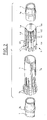
- La Figure 1 est une vue en coupe montrant le tuyau séparé de la pièce, dans un premier mode de réalisation;
- La Figure 2 est une vue en perspective de l'élément élastique s'encliquetant et de la bague de démontage;
- La Figure 3 est une vue semblable à la Figure 1, le tuyau étant monté dans la pièce;
- Les Figures 4 et 5 sont des vues semblables à la Figure 3 de deux autres modes de réalisation
- Figure 1 is a sectional view showing the pipe separated from the part, in a first embodiment;
- Figure 2 is a perspective view of the snap-in elastic member and the disassembly ring;
- Figure 3 is a view similar to Figure 1, the pipe being mounted in the room;
- Figures 4 and 5 are views similar to Figure 3 of two other embodiments
Au dessin, on voit en 1 un tuyau qui doit être fixé dans un perçage 2 d'une pièce 3.In the drawing, we see in 1 a pipe which must be fixed in a
La fixation du tuyau dans le perçage de la pièce 3 peut être assurée par un ressort circulaire 4 qui est emmanché sur le tuyau 1 et clippé sur celui-ci. A cet effet, ce ressort comporte une partie centrale cylindrique 4a qui peut présenter ou non une fente longitudinale 4b. Cette partie 4a est prolongée, du côté de l'extrémité du tuyau 1, par des pattes 4c et 4d. Les pattes 4c sont coniques, ou plates mais tangentes à un cône. Elles prennent appui derrière un bourrelet 1a du tuyau 1, ce qui empêche le retrait du ressort 4 lorsqu'il a été emmanché sur le tuyau. Les pattes 4d, qui sont au nombre de trois dans le mode de réalisation représenté, sont cylindriques avec le même diamètre que la partie centrale 4a et comportent un bord rabattu 4e prenant appui sur la face avant du bourrelet 1a. A son extrémité opposée, la partie 4a du ressort est prolongée par des pattes coniques 4f pouvant venir s'encliqueter lors du montage,dans un alésage conique 5 de la pièce 3, qui se raccorde par un alésage cylindrique 6 au perçage 2.The fixing of the pipe in the bore of the
Il est prévu une bague de démontage 7 qui présente sur toute sa longueur une fente longitudinale 7a et est emmanchée sur le tuyau 1, entre ce tuyau et les pattes coniniques 4f du ressort 4. Cette bague est prolongée vers l'arrière par des pattes fendues 7b qui arrêtent le déplacement de la bague vers l'arrière en venant buter contre un second bourrelet 1b du tuyau 1.There is provided a
Pour fixer le tuyau 1 dans la pièce 3, on emmanche sur ce tuyau la bague 7, puis le ressort 4. On dispose alors une bague d'appui 8 et un joint torique 9 sur le tuyau devant le bourrelet 1a et on emmanche le tout dans la pièce 3; en fin de mouvement, le joint se trouve dans le fond de l'alésage cylindrique 6 et les pattes coniques 4f s'encliquètent dans l'alésage conique 5 de la pièce 3 (Figure 3).To fix the pipe 1 in the
Pour démonter le tuyau, il suffit de pousser vers l'avant la bague 7 qui écarte les pattes 4c qui libèrent le bourrelet 1a du tuyau 1; celui-ci peut alors être retiré.To dismantle the pipe, it suffices to push forward the
On peut prévoir un capuchon 11 de protection anticorrosion qui recouvre la partie de la bague 7 extérieure au ressort 4, donc extérieure à la pièce 3 quand le tuyau 1 est monté. On fait coulisser ce capuchon vers l'arrière, lorsqu'on veut démonter le tuyau.An
Pour mieux assurer l'implantation du tuyau 1 dans la pièce 3, la bague de démontage 7 peut présenter un bourrelet annulaire 7c qui s'appuie sur la paroi de l'alésage 6 (voir Figure 4). Le capuchon 11 présente à sa base une lèvre mince annulaire 11a qui assure l'étanchéité en venant presser sur la pièce 3.To better ensure the establishment of the pipe 1 in the
Dans le mode de réalisation de la Figure 5, le tuyau 1 est fixé dans un perçage d'une pièce intermédiaire cylindrique 12 qui est vissée dans la pièce 3, ce qui permet d'avoir accès au joint torique 9.In the embodiment of FIG. 5, the pipe 1 is fixed in a hole in a cylindrical
Il va de soi que la présente invention ne doit pas être considérée comme limitée aux divers modes de réalisation décrits et représentés, mais en couvre, au contraire, toutes les variantes. C'est ainsi, en particulier, que le ressort 4 peut ne pas comporter la fente longitudinale 4b, auquel cas il faut prévoir un léger jeu entre ce ressort et la bague de démontage 7.It goes without saying that the present invention should not be considered as limited to the various embodiments described and shown, but on the contrary covers all variants. Thus, in particular, the
Claims (7)
caractérisé en ce que l'élément élastique (4) présente des pattes (4c) pouvant s'encliqueter derrière un bourrelet (1a) du tuyau (1),et en ce qu'il comporte une bague de démontage (7) qui présente une fente longitudinale (7a) et est montée coulissante sur le tuyau en pouvant s'engager entre celui-ci et les pattes (4c) de l'élément élastique.1. Quick coupling suitable for fixing a pipe (1) in a bore (2) of a part (3), comprising an elastic element (4) which can snap onto the pipe (1) and which can - even snap into the hole in the part (3).
characterized in that the elastic element (4) has tabs (4 c ) which can be snapped behind a bead (1 a ) of the pipe (1), and in that it comprises a dismounting ring (7) which has a longitudinal slot (7 a ) and is slidably mounted on the pipe, being able to engage between the latter and the tabs (4 c ) of the elastic element.
caractérisé en ce que la bague de démontage (7) présente une série de pattes fendues (7b) propres à coopérer avec un bourrelet (1b) du tuyau pour limiter le déplacement de la bague vers l'arrière.2. Quick coupling according to claim 1,
characterized in that the disassembly ring (7) has a series of split tabs (7 b ) capable of cooperating with a bead (1 b ) of the pipe to limit the movement of the ring backwards.
caractérisé en ce que les pattes (4c) sont coniques, ou plates et tangentes à un cône, et en ce que l'élément élastique (4) présente, entre certaines des pattes (4c), des pattes cylindriques (4d) qui comportent un bord rabattu (4e) pouvant prendre appui sur la face avant du bourrelet (1a).3. Connection according to claim 1 or 2,
characterized in that the legs (4 c ) are conical, or flat and tangent to a cone, and in that the elastic element (4) has, between some of the legs (4 c ), cylindrical legs (4 d ) which have a folded edge (4 e ) which can bear on the front face of the bead (1 a ).
caractérisé en ce que la bague de démontage (7) présente un bourrelet annulaire (7c) propre à prendre appui sur la paroi du perçage de la pièce.4. Connection according to one of the preceding claims,
characterized in that the dismantling ring (7) has an annular bead (7 c ) capable of bearing on the wall of the bore of the part.
caractérisé par un capuchon de protection (11) qui recouvre la partie de la bague (7) extérieure à l'élément élastique (4).5. Connection according to any one of the preceding claims,
characterized by a protective cap (11) which covers the part of the ring (7) external to the elastic element (4).
caractérisé en ce que le capuchon (11) présente, à sa base, une lèvre mince annulaire (11a) propre à presser sur la pièce (3).6. Connection according to claim 6,
characterized in that the cap (11) has, at its base, a thin annular lip (11 a ) suitable for pressing on the part (3).
caractérisé par une pièce intermèdiaire (12) dans un perçage de laquelle le tuyau peut être fixé et qui est vissée dans la pièce (3).7. Connection according to any one of the preceding claims,
characterized by an intermediate piece (12) in a bore of which the pipe can be fixed and which is screwed into the piece (3).
Applications Claiming Priority (2)
| Application Number | Priority Date | Filing Date | Title |
|---|---|---|---|
| FR8807134A FR2631681B1 (en) | 1988-05-20 | 1988-05-20 | QUICK CONNECTION FOR PIPE |
| FR8807134 | 1988-05-20 |
Publications (1)
| Publication Number | Publication Date |
|---|---|
| EP0343036A1 true EP0343036A1 (en) | 1989-11-23 |
Family
ID=9366710
Family Applications (1)
| Application Number | Title | Priority Date | Filing Date |
|---|---|---|---|
| EP89401291A Ceased EP0343036A1 (en) | 1988-05-20 | 1989-05-10 | Quick acting pipe coupling |
Country Status (2)
| Country | Link |
|---|---|
| EP (1) | EP0343036A1 (en) |
| FR (1) | FR2631681B1 (en) |
Cited By (3)
| Publication number | Priority date | Publication date | Assignee | Title |
|---|---|---|---|---|
| EP0451739A2 (en) * | 1990-04-11 | 1991-10-16 | Knapp Mikrohydraulik Kg | Coupling piece |
| WO1992008074A1 (en) * | 1990-10-24 | 1992-05-14 | Ford Motor Company Limited | A tube connector |
| EP0532242A2 (en) * | 1991-09-10 | 1993-03-17 | Bundy Corporation | Quick connect tubing connector and method of assembly |
Citations (7)
| Publication number | Priority date | Publication date | Assignee | Title |
|---|---|---|---|---|
| US2465197A (en) * | 1945-08-25 | 1949-03-22 | Newton L Chatham | Coupling |
| US2523770A (en) * | 1948-07-22 | 1950-09-26 | Gen Electric | Releasable hose coupling |
| US3711125A (en) * | 1971-06-29 | 1973-01-16 | Ford Motor Co | Quick connect fitting for a hydraulic conduit |
| DE2307154A1 (en) * | 1973-02-14 | 1974-08-22 | Daimler Benz Ag | HOSE OR PIPE CONNECTOR |
| DE2853281A1 (en) * | 1977-12-23 | 1979-06-28 | Ford Werke Ag | COUPLING FOR CONNECTING A PIPE TO A VESSEL |
| EP0193271A1 (en) * | 1985-02-27 | 1986-09-03 | Aeroquip AG | Push-in connect fitting |
| DE3533619A1 (en) * | 1985-04-24 | 1986-11-06 | Schmelzer Corp., Flint, Mich. | QUICK COUPLING FOR FLUID MEDIUM PIPES |
-
1988
- 1988-05-20 FR FR8807134A patent/FR2631681B1/en not_active Expired - Fee Related
-
1989
- 1989-05-10 EP EP89401291A patent/EP0343036A1/en not_active Ceased
Patent Citations (7)
| Publication number | Priority date | Publication date | Assignee | Title |
|---|---|---|---|---|
| US2465197A (en) * | 1945-08-25 | 1949-03-22 | Newton L Chatham | Coupling |
| US2523770A (en) * | 1948-07-22 | 1950-09-26 | Gen Electric | Releasable hose coupling |
| US3711125A (en) * | 1971-06-29 | 1973-01-16 | Ford Motor Co | Quick connect fitting for a hydraulic conduit |
| DE2307154A1 (en) * | 1973-02-14 | 1974-08-22 | Daimler Benz Ag | HOSE OR PIPE CONNECTOR |
| DE2853281A1 (en) * | 1977-12-23 | 1979-06-28 | Ford Werke Ag | COUPLING FOR CONNECTING A PIPE TO A VESSEL |
| EP0193271A1 (en) * | 1985-02-27 | 1986-09-03 | Aeroquip AG | Push-in connect fitting |
| DE3533619A1 (en) * | 1985-04-24 | 1986-11-06 | Schmelzer Corp., Flint, Mich. | QUICK COUPLING FOR FLUID MEDIUM PIPES |
Cited By (6)
| Publication number | Priority date | Publication date | Assignee | Title |
|---|---|---|---|---|
| EP0451739A2 (en) * | 1990-04-11 | 1991-10-16 | Knapp Mikrohydraulik Kg | Coupling piece |
| EP0451739A3 (en) * | 1990-04-11 | 1992-03-11 | Knapp Mikrohydraulik Kg | Coupling piece |
| US5197770A (en) * | 1990-04-11 | 1993-03-30 | Knapp Mikrohydraulik Kg | Coupling part |
| WO1992008074A1 (en) * | 1990-10-24 | 1992-05-14 | Ford Motor Company Limited | A tube connector |
| EP0532242A2 (en) * | 1991-09-10 | 1993-03-17 | Bundy Corporation | Quick connect tubing connector and method of assembly |
| EP0532242A3 (en) * | 1991-09-10 | 1994-05-18 | Bundy Corp | Quick connect tubing connector and method of assembly |
Also Published As
| Publication number | Publication date |
|---|---|
| FR2631681B1 (en) | 1990-08-24 |
| FR2631681A1 (en) | 1989-11-24 |
Similar Documents
| Publication | Publication Date | Title |
|---|---|---|
| EP1489327B1 (en) | Clutch release device and method of assembly | |
| EP0488844B1 (en) | Connection device, especially for assembling a hose to a car heat exchanger | |
| EP0469949B1 (en) | Quick-acting type coupling for the connection of a hose to a car heat exchanger | |
| FR2873185A1 (en) | IMPLANTATION CARTRIDGE FOR A PIPE CONNECTION INTENDED TO TAKE PLACE IN HOUSING | |
| FR2654489A1 (en) | Female pipework connection member | |
| FR2719095A1 (en) | Device for assembling bearing rings. | |
| EP1308662B1 (en) | Quick-acting disconnectable coupling for at least one tube | |
| FR2795156A1 (en) | Snap-on connector with adjustable sleeve used on motor vehicle for fuel line has rigid tubular end piece fitting into end of fuel line and sealed into end of connector piece | |
| EP0740101B1 (en) | Quick acting coupling having an autonomously loaded valve | |
| EP1056969B1 (en) | Snap-on connection for fluid conduit | |
| FR2681918A1 (en) | DEVICE FOR THE QUICK ASSEMBLY AND DISASSEMBLY OF TWO PARTS ON THE OTHER. | |
| FR2944851A1 (en) | SYSTEM FOR FASTENING A CONNECTION FOR CONDUCTING FLUID TRANSPORT TO A PARTITION. | |
| EP0396455A1 (en) | Snap-lock assembly for a motor vehicle heat exchanger | |
| WO2003025443A2 (en) | Connecting device with secure mounting | |
| EP0343036A1 (en) | Quick acting pipe coupling | |
| EP0833093A1 (en) | Device for sealingly butt-coupling two metal pipes | |
| EP0197874B1 (en) | Elastic hook element for instantaneous fluid conduits-coupling systems | |
| FR2760057A1 (en) | FREE WHEEL DEVICE WITH RETAINING FLANGE AND METHOD FOR PLACING THE FLANGE | |
| EP0327442B1 (en) | Connection between a heat exchanger and a tubular member | |
| FR2856122A1 (en) | Clutch throw-out bearing, has axial retaining strip connected directly on bead and having retaining units with control unit, at its free end, where strip traverses opening in radial flange of operating device | |
| EP1580478A1 (en) | Lock/Unlock pipe coupling | |
| FR2633353A1 (en) | ADJUSTING ASSEMBLY FOR CLUTCH STOP, ESPECIALLY FOR A MOTOR VEHICLE | |
| FR2787554A1 (en) | INTERMEDIATE FIXING ELEMENT OF A REFLECTOR ON A SUPPORT PART OF A MOTOR VEHICLE PROJECTOR, AND PROJECTOR COMPRISING SUCH AN ELEMENT | |
| EP0926375B1 (en) | Clutch release bearing with lateral guiding and connecting clips | |
| FR2810716A1 (en) | Connector for pipes forming part of car exhaust system comprises male and female connectors with conical sections which fit together at their widest part and biconical sleeve with narrower sections outwards which fits over them |
Legal Events
| Date | Code | Title | Description |
|---|---|---|---|
| PUAI | Public reference made under article 153(3) epc to a published international application that has entered the european phase |
Free format text: ORIGINAL CODE: 0009012 |
|
| AK | Designated contracting states |
Kind code of ref document: A1 Designated state(s): DE GB IT |
|
| 17P | Request for examination filed |
Effective date: 19891004 |
|
| 17Q | First examination report despatched |
Effective date: 19910103 |
|
| STAA | Information on the status of an ep patent application or granted ep patent |
Free format text: STATUS: THE APPLICATION HAS BEEN REFUSED |
|
| 18R | Application refused |
Effective date: 19920831 |
|
| APAF | Appeal reference modified |
Free format text: ORIGINAL CODE: EPIDOSCREFNE |