EP0343910B1 - Snap-lock fitting catheter for an implantable device - Google Patents
Snap-lock fitting catheter for an implantable device Download PDFInfo
- Publication number
- EP0343910B1 EP0343910B1 EP89305179A EP89305179A EP0343910B1 EP 0343910 B1 EP0343910 B1 EP 0343910B1 EP 89305179 A EP89305179 A EP 89305179A EP 89305179 A EP89305179 A EP 89305179A EP 0343910 B1 EP0343910 B1 EP 0343910B1
- Authority
- EP
- European Patent Office
- Prior art keywords
- section
- housing
- catheter
- outlet
- locking sleeve
- Prior art date
- Legal status (The legal status is an assumption and is not a legal conclusion. Google has not performed a legal analysis and makes no representation as to the accuracy of the status listed.)
- Expired - Lifetime
Links
Images

Classifications
-
- A—HUMAN NECESSITIES
- A61—MEDICAL OR VETERINARY SCIENCE; HYGIENE
- A61M—DEVICES FOR INTRODUCING MEDIA INTO, OR ONTO, THE BODY; DEVICES FOR TRANSDUCING BODY MEDIA OR FOR TAKING MEDIA FROM THE BODY; DEVICES FOR PRODUCING OR ENDING SLEEP OR STUPOR
- A61M39/00—Tubes, tube connectors, tube couplings, valves, access sites or the like, specially adapted for medical use
- A61M39/10—Tube connectors; Tube couplings
- A61M39/12—Tube connectors; Tube couplings for joining a flexible tube to a rigid attachment
-
- F—MECHANICAL ENGINEERING; LIGHTING; HEATING; WEAPONS; BLASTING
- F16—ENGINEERING ELEMENTS AND UNITS; GENERAL MEASURES FOR PRODUCING AND MAINTAINING EFFECTIVE FUNCTIONING OF MACHINES OR INSTALLATIONS; THERMAL INSULATION IN GENERAL
- F16L—PIPES; JOINTS OR FITTINGS FOR PIPES; SUPPORTS FOR PIPES, CABLES OR PROTECTIVE TUBING; MEANS FOR THERMAL INSULATION IN GENERAL
- F16L37/00—Couplings of the quick-acting type
- F16L37/08—Couplings of the quick-acting type in which the connection between abutting or axially overlapping ends is maintained by locking members
- F16L37/084—Couplings of the quick-acting type in which the connection between abutting or axially overlapping ends is maintained by locking members combined with automatic locking
-
- A—HUMAN NECESSITIES
- A61—MEDICAL OR VETERINARY SCIENCE; HYGIENE
- A61M—DEVICES FOR INTRODUCING MEDIA INTO, OR ONTO, THE BODY; DEVICES FOR TRANSDUCING BODY MEDIA OR FOR TAKING MEDIA FROM THE BODY; DEVICES FOR PRODUCING OR ENDING SLEEP OR STUPOR
- A61M39/00—Tubes, tube connectors, tube couplings, valves, access sites or the like, specially adapted for medical use
- A61M39/02—Access sites
- A61M39/0208—Subcutaneous access sites for injecting or removing fluids
- A61M2039/0211—Subcutaneous access sites for injecting or removing fluids with multiple chambers in a single site
-
- A—HUMAN NECESSITIES
- A61—MEDICAL OR VETERINARY SCIENCE; HYGIENE
- A61M—DEVICES FOR INTRODUCING MEDIA INTO, OR ONTO, THE BODY; DEVICES FOR TRANSDUCING BODY MEDIA OR FOR TAKING MEDIA FROM THE BODY; DEVICES FOR PRODUCING OR ENDING SLEEP OR STUPOR
- A61M39/00—Tubes, tube connectors, tube couplings, valves, access sites or the like, specially adapted for medical use
- A61M39/10—Tube connectors; Tube couplings
- A61M2039/1027—Quick-acting type connectors
-
- A—HUMAN NECESSITIES
- A61—MEDICAL OR VETERINARY SCIENCE; HYGIENE
- A61M—DEVICES FOR INTRODUCING MEDIA INTO, OR ONTO, THE BODY; DEVICES FOR TRANSDUCING BODY MEDIA OR FOR TAKING MEDIA FROM THE BODY; DEVICES FOR PRODUCING OR ENDING SLEEP OR STUPOR
- A61M39/00—Tubes, tube connectors, tube couplings, valves, access sites or the like, specially adapted for medical use
- A61M39/10—Tube connectors; Tube couplings
- A61M2039/1066—Tube connectors; Tube couplings having protection means, e.g. sliding sleeve to protect connector itself, shrouds to protect a needle present in the connector, protective housing, isolating sheath
-
- A—HUMAN NECESSITIES
- A61—MEDICAL OR VETERINARY SCIENCE; HYGIENE
- A61M—DEVICES FOR INTRODUCING MEDIA INTO, OR ONTO, THE BODY; DEVICES FOR TRANSDUCING BODY MEDIA OR FOR TAKING MEDIA FROM THE BODY; DEVICES FOR PRODUCING OR ENDING SLEEP OR STUPOR
- A61M39/00—Tubes, tube connectors, tube couplings, valves, access sites or the like, specially adapted for medical use
- A61M39/10—Tube connectors; Tube couplings
- A61M2039/1072—Tube connectors; Tube couplings with a septum present in the connector
-
- A—HUMAN NECESSITIES
- A61—MEDICAL OR VETERINARY SCIENCE; HYGIENE
- A61M—DEVICES FOR INTRODUCING MEDIA INTO, OR ONTO, THE BODY; DEVICES FOR TRANSDUCING BODY MEDIA OR FOR TAKING MEDIA FROM THE BODY; DEVICES FOR PRODUCING OR ENDING SLEEP OR STUPOR
- A61M39/00—Tubes, tube connectors, tube couplings, valves, access sites or the like, specially adapted for medical use
- A61M39/02—Access sites
- A61M39/0208—Subcutaneous access sites for injecting or removing fluids
-
- Y—GENERAL TAGGING OF NEW TECHNOLOGICAL DEVELOPMENTS; GENERAL TAGGING OF CROSS-SECTIONAL TECHNOLOGIES SPANNING OVER SEVERAL SECTIONS OF THE IPC; TECHNICAL SUBJECTS COVERED BY FORMER USPC CROSS-REFERENCE ART COLLECTIONS [XRACs] AND DIGESTS
- Y10—TECHNICAL SUBJECTS COVERED BY FORMER USPC
- Y10S—TECHNICAL SUBJECTS COVERED BY FORMER USPC CROSS-REFERENCE ART COLLECTIONS [XRACs] AND DIGESTS
- Y10S128/00—Surgery
- Y10S128/912—Connections and closures for tubes delivering fluids to or from the body
-
- Y—GENERAL TAGGING OF NEW TECHNOLOGICAL DEVELOPMENTS; GENERAL TAGGING OF CROSS-SECTIONAL TECHNOLOGIES SPANNING OVER SEVERAL SECTIONS OF THE IPC; TECHNICAL SUBJECTS COVERED BY FORMER USPC CROSS-REFERENCE ART COLLECTIONS [XRACs] AND DIGESTS
- Y10—TECHNICAL SUBJECTS COVERED BY FORMER USPC
- Y10S—TECHNICAL SUBJECTS COVERED BY FORMER USPC CROSS-REFERENCE ART COLLECTIONS [XRACs] AND DIGESTS
- Y10S285/00—Pipe joints or couplings
- Y10S285/921—Snap-fit
-
- Y—GENERAL TAGGING OF NEW TECHNOLOGICAL DEVELOPMENTS; GENERAL TAGGING OF CROSS-SECTIONAL TECHNOLOGIES SPANNING OVER SEVERAL SECTIONS OF THE IPC; TECHNICAL SUBJECTS COVERED BY FORMER USPC CROSS-REFERENCE ART COLLECTIONS [XRACs] AND DIGESTS
- Y10—TECHNICAL SUBJECTS COVERED BY FORMER USPC
- Y10S—TECHNICAL SUBJECTS COVERED BY FORMER USPC CROSS-REFERENCE ART COLLECTIONS [XRACs] AND DIGESTS
- Y10S604/00—Surgery
- Y10S604/905—Aseptic connectors or couplings, e.g. frangible, piercable
Definitions
- This invention relates to an implantable device and, in particular, to a vascular access device that is implanted subcutaneously.
- a variety of implantable access devices are known and have been brought to the point of commercial acceptance.
- Typical of the commercially available devices is the INFUSAID Infus-a-PortTM.
- This device comprises, in its most basic form, an implantable port having access via a septum at a perpendicular angle to the skin via a needle. It has coupled to it a percutaneous catheter extending generally at a right angle to the direction of needle access to the port's inlet.
- implantable devices use a variety of materials, typically plastic such as PVC, Teflon, polyethylene, polypropylene, polyurethane, polycarbonate, polythermalsulfane, polysulphone, polyolefin, nylon and the like. Additionally silicon and rubber may be employed, while special components can be made of stainless steel or titanium.
- plastic such as PVC, Teflon, polyethylene, polypropylene, polyurethane, polycarbonate, polythermalsulfane, polysulphone, polyolefin, nylon and the like.
- silicon and rubber may be employed, while special components can be made of stainless steel or titanium.
- an implantable drug dispensing reservoir employs a twist-lock catheter coupled to a bayonet type connection. That is, the implantable port has a T-slot into which a metallic flanged fitting is fitted and rotated into a locking arrangement.
- the '394 patent also employs a tab which is sutured into place against the base plate of the port to prevent detachment of the twist-lock connector from the port body.
- U.S. Patent 4,704,103 employs a catheter coupling using a coaxial elastomer clamping member that is deformed as a pressure sleeve is screwed into the port.
- a rigid hollow support projects from the outlet bore and the catheter slides over it. Thus fluid communication is maintained as the catheter is clamped into position.
- Such a system is difficult to assemble in situ and contains a large number of components requiring surgeon time and precision.
- French patent application FR-A-2 586 569 discloses an implantable device in which the catheter is secured to a connection nozzle by means of a U-shaped clip which is fitted outside the port housing.
- the catheter is difficult to engage to the implanted port during an implantation procedure.
- the implantation of such a drug delivery device should be as simple as possible to minimize patient trauma and the degree of skill required by the surgeon.
- the reservoir is implanted subcutaneously at a location in the body cavity of the patient to provide needle access for infusion of medication.
- the catheter is then placed having one end at the drug delivery site and having the other end attached to the port.
- devices which require twist lock fittings and the like are difficult to connect in vivo and difficult to utilize in practice.
- connection in addition to providing the above requirements, establishes a fluid-tight coupling between the catheter and the implantable reservoir.
- Yet another object of this invention is to provide an improved coupling between the catheter and an implantable port which is leak-tight and may be connected in a quick, simple manner.
- an access device for implantation comprising a housing with a reservoir therein, a self-sealing septum to provide subcutaneous access to said reservoir, an outlet in fluid communication with said reservoir and having a nipple section therein, and a catheter having one end slidably mounted over said nipple section, characterised in that there is provided a locking sleeve having a through-hole for slidably mounting onto said catheter, said locking sleeve having a series of radially expansible fingers which slide over said nipple section and engage said housing in an outlet cavity while compressing said catheter thereby locking said catheter and said sleeve to said housing and provide, upon engagement, an audible or tactile indication that locking has been achieved.
- This connection technique may be used for both single and double lumen catheters.
- the said outlet cavity comprises an opening of first cross-sectional area for receiving a first section of said outlet and an opening of second cross-sectional area greater than said first cross-sectional area for receiving a second (nipple) section of said outlet, said second cross-sectional area positioned inward from exit of said outlet cavity into said housing.
- the first section of said outlet may comprise an anchoring portion to adhere said outlet to said housing, said nipple section having a flange abutting said housing at the opening of said second area to prevent further insertion of said outlet into said housing.
- the said housing further preferably comprises a shoulder section of reduced area to engage outer portions of said fingers when said locking sleeve slides over said nipple section.
- the said outer portions of said fingers may comprise a first inner section engaging an inner portion of said housing shoulder section and an adjacent second outer section of reduced area engaging an outer portion of said shoulder section, whereby said fingers are compressed inward by said second outer portion of said shoulder section when said locking sleeve slides over said nipple section and then expand radially outward to engage said inner portion.
- the said expansible fingers are preferably disposed circumferentially around said locking sleeve.
- the locking sleeve may comprise a generally cylindrical outer section, a generally tapered conical outer section, or a saddle shaped outer section having an annular recess to permit gripping.
- the catheter comprises a pair or lumens separated by an internal wall
- the housing comprises first and second reservoirs, first and second self-sealing septums and fluid communication means coupling a respective lumen to a respective reservoir.
- the nipple section may comprise an elongated barbed member having conduits coupling respective lumens to said fluid communication means and an elongation slot engaging said internal wall of said catheter.
- the outlet comprises a conical wall section, said radially expansible fingers being compressed as said locking sleeve slides over said nipple.
- the said conical wall section may have a circumferential groove, and the locking sleeve an annular shoulder engaging said groove to lock said sleeve to said housing and provide an audible or tactile indication that locking has occurred.
- the implantable device may be similar to a commercial Infus-a-PortTM comprising a generally round shaped housing (10) having a recess forming a reservoir (12) for retaining medication.
- a septum (14) is formed utilizing a self-sealing polymer such as silicon rubber or latex and is adapted to permit access utilizing a hypodermic needle to the reservoir (12).
- the housing (10) may also be formed of a compatible polymeric material. As illustrated in Figs.
- the septum (14) is press fitted into the housing (10), the housing having a generally rounded shoulder portion (16) to provide a tactile reference for locating the septum (14). That is, during charging of the reservoir (12), the technician physically locates the housing (10) by tactilely sensing the location of the septum (14) as a function of determining the position of the annular shoulder portion (16).
- Fig. 1 illustrates an attachment hole (18) which is used to suture the housing (10) into position within a body cavity. While one such suture hole (18) is illustrated, it will be understood that a plurality of such holes may be used to adequately anchor the device (10) in place.
- An outlet (20) from the reservoir (12) is formed by placing a barbed fitting or nipple component in the outlet cavity (22) of the housing (10).
- the outlet (20) may typically have a self-tapping threaded first section (24), or another such technique, for anchoring a distal end of the fitting in fluid contact with the reservoir (12).
- the outlet cavity (22) is shaped to have a generally cylindrical section (26) with an inside diameter slightly larger than that of the anchoring portion of (24).
- a gradually tapered section (28) is used to receive the fingers, to be described herein, forming a portion of the snap-lock fitting.
- a wall (30) defines a positive stop by which a shoulder portion or flange (32) of the barbed fitting seats to prevent impingement into the reservoir.
- the second section (34) of the outlet (20) has a nipple which, as illustrated in Fig. 3, protrudes slightly beyond the outer wall of the housing (10). Further, as illustrated in Fig. 3, the housing (10) has a generally annular shoulder section (36) against which the fitting mounted on the catheter seats. It can be appreciated that the housing (10) having the various cavities can be formed by molding plastic with the septum (14) inserted during manufacture.
- the catheter (40) is made from an insert material such as a silicone and is initially supplied in a suitable length so that one end, not illustrated, can be located at the drug delivery site.
- a snap-lock fitting or locking sleeve (42) comprises a barrel section and an integral series of circumferentially disposed, radially expansible locking fingers (44). Each of the locking fingers (44) has an outwardly extending circumferential thickened portion and an inwardly positioned recessed portion. While the docking sleeve (42) is illustrated in Figs. 1-3 as generally cylindrical, other configurations may be used.
- Fig. 4A illustrates the generally cylindrical or barrel shaped locking sleeve while Fig. 4B illustrates a tapered locking sleeve.
- Fig. 4C illustrates the fitting of Fig. 4C.
- the fitting has a generally extending circumferential recess or saddle shaped outer section (43) to allow finger grip on the locking sleeve (42). That is, the surgeon may physically grip in the region (43) and have a positive holding zone defined by the rearwardly extending shoulder portion (46).
- the locking sleeve may be physically separated from the housing.
- the housing (10) is first implanted into the body cavity at a convenient site to allow for access via a hypodermic needle.
- the distal end of the catheter (40) is positioned at the infusion site and the catheter is trimmed to its desired length at the proximal end (50).
- the locking sleeve (42) is then slid onto the proximal end (50) of the catheter (40) so that the proximal end of the catheter extends about 1.3-2.5 cm (0.5-1.0 inches) beyond the fitting.
- the catheter (40) is then urged over the nipple tip of (34) of the outlet (20). The catheter then, as illustrated in Fig.
- dual reservoir port housing (100) comprises an implantable port having a pair of self-sealing septums (102) and (104).
- each of the septums (102) and (104) is a self-sealing polymer such as silicon rubber or latex and adapted to permit access utilizing a hypodermic needle to the reservoirs, not illustrated.
- Housing (100) may also be formed of a compatible polymeric material.
- the septums are press-fitted into the housing with the housing having a pair of rounded shoulder portions (106) and (108).
- the shoulder portions are used to provide a tactile reference for locating the respective septum. While illustrated in Fig. 5 as having a generally similar shape, the shoulder portions (106) and (108) may have different contours such as radius or squared-off or a point to provide the surgeon with a point of reference for determining which septum is being accessed.
- a series of suture holes (110) is provided on the periphery of the body for affixing the implantable device within a body cavity.
- Fig. 5 therefore utilizes two distinct reservoirs which are coupled to discrete infusion sites by means of a double lumen catheter (116).
- This double lumen catheter has two parallel lumens, (118) and (120), separated by means of a divider or internal wall (122).
- the nipple section of Fig. 1 must provide parallel flow channels. As illustrated in Fig. 5, this nipple section (124) has a barbed member and a pair of conduits (126) and (128) to provide fluid communication with the lumens (118) and (120) of the catheter (116). Additionally, a centrally disposed recess or elongation slot (130) is provided so that the internal wall (122) will engage the nipple section (124) so that alignment is established between the conduits (126) and (128) and the lumens (118) and (120) of the catheter.
- the nipple section (124) is anchored into the housing (100) so that fluid communication is maintained between conduits (132) and (134) which provide separate flow paths between each lumen of the catheter through (124) into a respective reservoir in the implantable device.
- the nipple is secured within the housing, and the pair of O-rings (136) and (138) are provided to isolate the flow path (126) to conduit (132) and the flow path (128) to conduit (134).
- the nipple section is anchored by means of a shoulder or flange (140) which rests against an internal wall of the housing (100).
- the snap-lock fitting (142) is different from that of the locking sleeve illustrated in the first embodiment. While it is an elongated cylindrical member which slides over the catheter (116), the fingers (144) are forced to move inward toward the catheter around the fitting, gripping to provide a leak-tight connection. To achieve this inward movement, the internal wall (148) is radiused inward so that its circumference progressively decreases.
- the sleeve or snap-lock fitting (142) has an inside diameter groove (152) which allows the fingers (144) to flex inward.
- a small annular locking tooth (154) is provided to engage the annular detent or notch (150). The tooth (154) is physically compressed by plastic deformation to snap into the annular groove (150).
- the assembly is provided in a manner generally similar to that of the first embodiment.
- a double lumen catheter is slid into engagement with the barbed member of the nipple section (124) with the internal wall (122) engaging the elongation slot (130) for purposes of alignment.
- the proximal end of the catheter (116) abuts against the shoulder (140).
- fluid communication from both lumens of the catheter is initially established through the nipple section and conduits (132) and (134) into each reservoir of the implantable device (100).
- the snap-lock fitting (142) is then slid over the catheter (116).
- the fingers are urged inward by the wall (148) as the snap-lock fitting is inserted into the opening in the housing. Inward flexing of the fingers will close the groove (152). As the fingers (144) deform inwardly, they tend to compress the outer circumferential wall of the catheter against the barbs.
Abstract
Description
- This invention relates to an implantable device and, in particular, to a vascular access device that is implanted subcutaneously. Within the prior art, a variety of implantable access devices are known and have been brought to the point of commercial acceptance. Typical of the commercially available devices is the INFUSAID Infus-a-Port™. This device comprises, in its most basic form, an implantable port having access via a septum at a perpendicular angle to the skin via a needle. It has coupled to it a percutaneous catheter extending generally at a right angle to the direction of needle access to the port's inlet. These implantable devices use a variety of materials, typically plastic such as PVC, Teflon, polyethylene, polypropylene, polyurethane, polycarbonate, polythermalsulfane, polysulphone, polyolefin, nylon and the like. Additionally silicon and rubber may be employed, while special components can be made of stainless steel or titanium.
- An example of a self-sealing implantable body utilizing an integral housing is described in U.S. Patent 4,543,088. As illustrated therein, fluid communication between the internal reservoir and catheter (not shown) is via a passageway. While the catheter is not illustrated, the '088 patent mentions the use of rigid connectors which can be incorporated in the fluid passageway to provide attachment of catheters and tubing to the implanted port.
- An example of such rigid connection is found in U.S. patent 4,673,394. As illustrated and described in that patent, an implantable drug dispensing reservoir employs a twist-lock catheter coupled to a bayonet type connection. That is, the implantable port has a T-slot into which a metallic flanged fitting is fitted and rotated into a locking arrangement. The '394 patent also employs a tab which is sutured into place against the base plate of the port to prevent detachment of the twist-lock connector from the port body.
- Examples of press couplings of catheters into implantable ports are illustrated in and described in U.S. Patents 4,645,495, 4,692,146, 4,710,167, and 4,710,174. In each, press fitting by frictional contact is used to hold the catheter in place with the port body. In the '146 patent, a metal nipple or tube may be used to prevent inadvertent puncture of the catheter itself. U.S. Patent 4,464,178 is also directed to an implantable port having an outlet catheter and employs a retainer having a pair of ears which engage matching voids in the reservoir. Such a retainer provides a positive locking and prevents the catheter from disengaging. However, problems in manufacture and replacement of the catheter are inherent in such a scheme. Another alternative of frictional yet detachable mounting of a catheter to an implantable device is found in U.S. Patent 4,581,020, which employs a tapered fluid connector which frictionally fits into an inlet to allow the catheter assembly to be detached.
- U.S. Patent 4,704,103 employs a catheter coupling using a coaxial elastomer clamping member that is deformed as a pressure sleeve is screwed into the port. To prevent the clamping member from crushing the catheter, a rigid hollow support projects from the outlet bore and the catheter slides over it. Thus fluid communication is maintained as the catheter is clamped into position. Such a system is difficult to assemble in situ and contains a large number of components requiring surgeon time and precision.
- French patent application FR-A-2 586 569 discloses an implantable device in which the catheter is secured to a connection nozzle by means of a U-shaped clip which is fitted outside the port housing.
- In U.S. patent 4,632,435 a tubing connector system is described which requires the use of a connector assembly tool to couple the ends of each tube by compressing together a connector body and each clamping ring.
- One of the difficulties with these various prior art techniques is that the catheter is difficult to engage to the implanted port during an implantation procedure. The implantation of such a drug delivery device should be as simple as possible to minimize patient trauma and the degree of skill required by the surgeon. In general, the reservoir is implanted subcutaneously at a location in the body cavity of the patient to provide needle access for infusion of medication. The catheter is then placed having one end at the drug delivery site and having the other end attached to the port. Given limited space, devices which require twist lock fittings and the like are difficult to connect in vivo and difficult to utilize in practice.
- Moreover, in many of the devices which simply fit by means of pressure fitting, friction or the like, there is no indication that a complete and positive connection has been made. That is, no audible or tactile reference occurs indicating that an acceptable connection between the catheter and the port has been achieved. During the implantation procedure the surgeon must visually check or pull to determine whether the components have been coupled. Finally, devices which utilize machined parts and the like are more expensive to manufacture, have problems of material incompatibility, and present, to varying degrees, the problems of patient discomfort.
- An overriding consideration is that the connection, in addition to providing the above requirements, establishes a fluid-tight coupling between the catheter and the implantable reservoir.
- Given the deficiencies of the prior-art, it is an object of this invention to provide an improved catheter to implantable port coupling which provides an indication of a complete and operative connection between elements.
- Yet another object of this invention is to provide an improved coupling between the catheter and an implantable port which is leak-tight and may be connected in a quick, simple manner.
- These and other objects are accomplished by the present invention. According to the present invention, there is provided an access device for implantation comprising a housing with a reservoir therein, a self-sealing septum to provide subcutaneous access to said reservoir, an outlet in fluid communication with said reservoir and having a nipple section therein, and a catheter having one end slidably mounted over said nipple section, characterised in that there is provided a locking sleeve having a through-hole for slidably mounting onto said catheter, said locking sleeve having a series of radially expansible fingers which slide over said nipple section and engage said housing in an outlet cavity while compressing said catheter thereby locking said catheter and said sleeve to said housing and provide, upon engagement, an audible or tactile indication that locking has been achieved. This connection technique may be used for both single and double lumen catheters.
- Preferably the said outlet cavity comprises an opening of first cross-sectional area for receiving a first section of said outlet and an opening of second cross-sectional area greater than said first cross-sectional area for receiving a second (nipple) section of said outlet, said second cross-sectional area positioned inward from exit of said outlet cavity into said housing. The first section of said outlet may comprise an anchoring portion to adhere said outlet to said housing, said nipple section having a flange abutting said housing at the opening of said second area to prevent further insertion of said outlet into said housing.
- In another aspect of the invention, the said housing further preferably comprises a shoulder section of reduced area to engage outer portions of said fingers when said locking sleeve slides over said nipple section. The said outer portions of said fingers may comprise a first inner section engaging an inner portion of said housing shoulder section and an adjacent second outer section of reduced area engaging an outer portion of said shoulder section, whereby said fingers are compressed inward by said second outer portion of said shoulder section when said locking sleeve slides over said nipple section and then expand radially outward to engage said inner portion. The said expansible fingers are preferably disposed circumferentially around said locking sleeve.
- The locking sleeve may comprise a generally cylindrical outer section, a generally tapered conical outer section, or a saddle shaped outer section having an annular recess to permit gripping.
- In an alternative embodiment, the catheter comprises a pair or lumens separated by an internal wall, the housing comprises first and second reservoirs, first and second self-sealing septums and fluid communication means coupling a respective lumen to a respective reservoir. The nipple section may comprise an elongated barbed member having conduits coupling respective lumens to said fluid communication means and an elongation slot engaging said internal wall of said catheter.
- In a further aspect of the present invention, the outlet comprises a conical wall section, said radially expansible fingers being compressed as said locking sleeve slides over said nipple. The said conical wall section may have a circumferential groove, and the locking sleeve an annular shoulder engaging said groove to lock said sleeve to said housing and provide an audible or tactile indication that locking has occurred.
- This invention will be described in greater detail by referring to the attached drawings and a description of the preferred embodiments that follow.
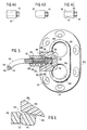
- Fig. 1 is a schematic perspective view illustrating the basic components of a first embodiment of this invention prior to attachment;
- Fig. 2 is a schematic perspective view of the components of a first embodiment of this invention during an intermediate stage of attachment;
- Fig. 3 is a schematic elevation view illustrating the components of a first embodiment of this invention in an engagement or locked position; and
- Figs. 4A, 4B, 4C illustrate in a schematic view, three configurations of the snap-lock fitting in accordance with this invention;
- Fig. 5 illustrates a second embodiment of this invention for use with a double lumen catheter; and
- Fig. 6 is a schematic view of the details of the engagement structure of the second embodiment of this invention.
- Referring now to Figs. 1-3, the construction and assembly of this invention pursuant to a first embodiment of the invention is depicted. The implantable device may be similar to a commercial Infus-a-Port™ comprising a generally round shaped housing (10) having a recess forming a reservoir (12) for retaining medication. A septum (14) is formed utilizing a self-sealing polymer such as silicon rubber or latex and is adapted to permit access utilizing a hypodermic needle to the reservoir (12). The housing (10) may also be formed of a compatible polymeric material. As illustrated in Figs. 1 and 3, the septum (14) is press fitted into the housing (10), the housing having a generally rounded shoulder portion (16) to provide a tactile reference for locating the septum (14). That is, during charging of the reservoir (12), the technician physically locates the housing (10) by tactilely sensing the location of the septum (14) as a function of determining the position of the annular shoulder portion (16).
- Fig. 1 illustrates an attachment hole (18) which is used to suture the housing (10) into position within a body cavity. While one such suture hole (18) is illustrated, it will be understood that a plurality of such holes may be used to adequately anchor the device (10) in place.
- An outlet (20) from the reservoir (12) is formed by placing a barbed fitting or nipple component in the outlet cavity (22) of the housing (10). As illustrated in Fig. 3, the outlet (20) may typically have a self-tapping threaded first section (24), or another such technique, for anchoring a distal end of the fitting in fluid contact with the reservoir (12). The outlet cavity (22) is shaped to have a generally cylindrical section (26) with an inside diameter slightly larger than that of the anchoring portion of (24). A gradually tapered section (28) is used to receive the fingers, to be described herein, forming a portion of the snap-lock fitting. A wall (30) defines a positive stop by which a shoulder portion or flange (32) of the barbed fitting seats to prevent impingement into the reservoir.
- The second section (34) of the outlet (20) has a nipple which, as illustrated in Fig. 3, protrudes slightly beyond the outer wall of the housing (10). Further, as illustrated in Fig. 3, the housing (10) has a generally annular shoulder section (36) against which the fitting mounted on the catheter seats. It can be appreciated that the housing (10) having the various cavities can be formed by molding plastic with the septum (14) inserted during manufacture.
- Referring again to Fig. 1, the catheter and the snap-lock fitting are illustrated. The catheter (40) is made from an insert material such as a silicone and is initially supplied in a suitable length so that one end, not illustrated, can be located at the drug delivery site. A snap-lock fitting or locking sleeve (42) comprises a barrel section and an integral series of circumferentially disposed, radially expansible locking fingers (44). Each of the locking fingers (44) has an outwardly extending circumferential thickened portion and an inwardly positioned recessed portion. While the docking sleeve (42) is illustrated in Figs. 1-3 as generally cylindrical, other configurations may be used.
- Referring to Figs. 4A, 4B and 4C, three alternatives are illustrated. Fig. 4A illustrates the generally cylindrical or barrel shaped locking sleeve while Fig. 4B illustrates a tapered locking sleeve. Those devices are used in a situation where the snap-lock connector will not be removed once it is coupled to the port housing (10). If removal or replacement is perceived, the fitting of Fig. 4C may be employed. As illustrated in that figure, the fitting has a generally extending circumferential recess or saddle shaped outer section (43) to allow finger grip on the locking sleeve (42). That is, the surgeon may physically grip in the region (43) and have a positive holding zone defined by the rearwardly extending shoulder portion (46). With one hand on the locking sleeve (42) and a second hand on the housing (10), the locking sleeve may be physically separated from the housing.
- For installation of this device, the housing (10) is first implanted into the body cavity at a convenient site to allow for access via a hypodermic needle. The distal end of the catheter (40) is positioned at the infusion site and the catheter is trimmed to its desired length at the proximal end (50). The locking sleeve (42) is then slid onto the proximal end (50) of the catheter (40) so that the proximal end of the catheter extends about 1.3-2.5 cm (0.5-1.0 inches) beyond the fitting. The catheter (40) is then urged over the nipple tip of (34) of the outlet (20). The catheter then, as illustrated in Fig. 2, is pushed on the fitting (whereby its outside wall deforms) and abuts against the flange (32). Thus, fluid communication is established from the reservoir (12) through the outlet (20) and into the catheter (40). Next, the locking sleeve (42) is slid up to the port body and snaps into the outlet cavity (22) of the port housing. As the fitting slides over the nipple, the fingers (44) spread and then snap into locking engagement on the rear shoulder of the nipple portion of the fitting. The audible and tactile action of the spring fingers assures a good contact and at the same time provides an indication that an affirmative connection has been made. This placement of the locking sleeve also provides for stress relief of the catheter in case of bending on the nipple section. The action of sliding the locking sleeve over the nipple causes local compression and elongation of the catheter material. This material bunches up between the flange (32) and the fingers (44) providing a degree of reserve in case the catheter is accidentally pulled.
- Referring now to Figs. 5 and 6, a second embodiment of this invention is depicted. In Fig. 5 dual reservoir port housing (100) comprises an implantable port having a pair of self-sealing septums (102) and (104). As in the case of the embodiment of Fig. 1, each of the septums (102) and (104) is a self-sealing polymer such as silicon rubber or latex and adapted to permit access utilizing a hypodermic needle to the reservoirs, not illustrated. Housing (100) may also be formed of a compatible polymeric material. The septums are press-fitted into the housing with the housing having a pair of rounded shoulder portions (106) and (108). The shoulder portions are used to provide a tactile reference for locating the respective septum. While illustrated in Fig. 5 as having a generally similar shape, the shoulder portions (106) and (108) may have different contours such as radius or squared-off or a point to provide the surgeon with a point of reference for determining which septum is being accessed.
- A series of suture holes (110) is provided on the periphery of the body for affixing the implantable device within a body cavity.
- The embodiment of Fig. 5 therefore utilizes two distinct reservoirs which are coupled to discrete infusion sites by means of a double lumen catheter (116). This double lumen catheter has two parallel lumens, (118) and (120), separated by means of a divider or internal wall (122).
- To accommodate the double lumen catheter (116), the nipple section of Fig. 1 must provide parallel flow channels. As illustrated in Fig. 5, this nipple section (124) has a barbed member and a pair of conduits (126) and (128) to provide fluid communication with the lumens (118) and (120) of the catheter (116). Additionally, a centrally disposed recess or elongation slot (130) is provided so that the internal wall (122) will engage the nipple section (124) so that alignment is established between the conduits (126) and (128) and the lumens (118) and (120) of the catheter.
- The nipple section (124) is anchored into the housing (100) so that fluid communication is maintained between conduits (132) and (134) which provide separate flow paths between each lumen of the catheter through (124) into a respective reservoir in the implantable device. The nipple is secured within the housing, and the pair of O-rings (136) and (138) are provided to isolate the flow path (126) to conduit (132) and the flow path (128) to conduit (134). As in the case of the first embodiment, the nipple section is anchored by means of a shoulder or flange (140) which rests against an internal wall of the housing (100).
- The snap-lock fitting (142) is different from that of the locking sleeve illustrated in the first embodiment. While it is an elongated cylindrical member which slides over the catheter (116), the fingers (144) are forced to move inward toward the catheter around the fitting, gripping to provide a leak-tight connection. To achieve this inward movement, the internal wall (148) is radiused inward so that its circumference progressively decreases. The sleeve or snap-lock fitting (142) has an inside diameter groove (152) which allows the fingers (144) to flex inward. At its outer periphery, as illustrated in Fig. 6, a small annular locking tooth (154) is provided to engage the annular detent or notch (150). The tooth (154) is physically compressed by plastic deformation to snap into the annular groove (150).
- In operation, the assembly is provided in a manner generally similar to that of the first embodiment. A double lumen catheter is slid into engagement with the barbed member of the nipple section (124) with the internal wall (122) engaging the elongation slot (130) for purposes of alignment. The proximal end of the catheter (116) abuts against the shoulder (140). Thus fluid communication from both lumens of the catheter is initially established through the nipple section and conduits (132) and (134) into each reservoir of the implantable device (100).
- The snap-lock fitting (142) is then slid over the catheter (116). The fingers are urged inward by the wall (148) as the snap-lock fitting is inserted into the opening in the housing. Inward flexing of the fingers will close the groove (152). As the fingers (144) deform inwardly, they tend to compress the outer circumferential wall of the catheter against the barbs.
- When the locking tooth (154) engages the notch (150), the audible and tactile clicking effect occurs locking the fitting (142) in place. Thus, snap-locking occurs. It is apparent that this snap-lock fitting opening arrangement used in Fig. 5 may also be employed relative to the single lumen catheter of Fig. 1.
- While this invention has been described relative to preferred embodiments and modifications of the snap-lock fitting, it is apparent that modifications of this invention may be practiced without departing from the essential scope thereof.
Claims (13)
- An access device for implantation comprising a housing (10) with a reservoir (12) therein, a self-sealing septum (14) to provide subcutaneous access to said reservoir, an outlet (20) in fluid communication with said reservoir and having a nipple section (34) therein, and a catheter (40) having one end (50) slidably mounted over said nipple section, characterised in that there is provided a locking sleeve (42) having a through-hole for slidably mounting onto said catheter, said locking sleeve having a series of radially expansible fingers (44) which slide over said nipple section and engage said housing in an outlet cavity (22) while compressing said catheter thereby locking said catheter and said sleeve to said housing and provide, upon engagement, an audible or tactile indication that locking has been achieved.
- The device of Claim 1, wherein said outlet cavity (22) comprises an opening of first cross-sectional area (26) for receiving a first section (24) of said outlet (20) and an opening of second cross-sectional area (28) greater than said first cross-sectional area for receiving a second section (34) of said outlet, said second cross-sectional area positioned inward from exit of said outlet cavity into said housing.
- The device of Claim 2, wherein said first section (24) of said outlet (20) comprises an anchoring portion to adhere said outlet to said housing (10), said nipple section (34) having a flange (32) abutting said housing at the opening of said second area (28) to prevent further insertion of said outlet into said housing.
- The device of Claim 2, wherein said housing (10) further comprises a shoulder section (36) of reduced area to engage outer portions of said fingers (44) when said locking sleeve (42) slides over said nipple section (34).
- The device of Claim 4, wherein said outer portions of said fingers (44) comprise a first inner section engaging an inner portion of said housing shoulder section (36) and an adjacent second outer section of reduced area engaging an outer portion of said shoulder section, whereby said fingers are compressed inward by said second outer portion of said shoulder section when said locking sleeve (42) slides over said nipple section (34) and then expand radially outward to engage said inner portion.
- The device of Claim 1, wherein said expansible fingers (44) are disposed circumferentially around said locking sleeve (42).
- The device of Claim 1, wherein said locking sleeve (42) comprises a generally cylindrical outer section.
- The device of Claim 1, wherein said locking sleeve (42) comprises a generally tapered conical outer section.
- The device of Claim 1, wherein said locking sleeve (42) comprises a saddle shaped outer section (43) having an annular recess to permit gripping.
- The device of Claim 1, wherein the catheter (116) comprises a pair of lumens (118,120) separated by an internal wall (122), and the housing (100) comprises first and second reservoirs, first and second self-sealing septums (102, 104) and fluid communication means (132, 134) coupling a respective lumen to a respective reservoir.
- The device of Claim 10 wherein the nipple section (124) comprises an elongated barbed member having conduits (126, 128) coupling respective lumens (118, 120) to said fluid communication means (132, 134) and an elongation slot (130) engaging said internal wall of said catheter.
- The device of Claim 1, wherein said outlet (20) comprises a conical wall section, said radially expansible fingers (44) being compressed as said locking sleeve (42) slides over said nipple.
- The device of Claim 12, wherein said conical wall section has a circumferential groove, and locking sleeve (42) has an annular shoulder engaging said groove to lock said sleeve to said housing and provide an audible or tactile indication that locking has occurred.
Priority Applications (1)
| Application Number | Priority Date | Filing Date | Title |
|---|---|---|---|
| AT89305179T ATE90579T1 (en) | 1988-05-26 | 1989-05-23 | SNAP CONNECTOR FOR CATHETER ON AN IMPLANTABLE DEVICE. |
Applications Claiming Priority (2)
| Application Number | Priority Date | Filing Date | Title |
|---|---|---|---|
| US200156 | 1988-05-26 | ||
| US07/200,156 US4929236A (en) | 1988-05-26 | 1988-05-26 | Snap-lock fitting catheter for an implantable device |
Publications (3)
| Publication Number | Publication Date |
|---|---|
| EP0343910A2 EP0343910A2 (en) | 1989-11-29 |
| EP0343910A3 EP0343910A3 (en) | 1990-02-14 |
| EP0343910B1 true EP0343910B1 (en) | 1993-06-16 |
Family
ID=22740564
Family Applications (1)
| Application Number | Title | Priority Date | Filing Date |
|---|---|---|---|
| EP89305179A Expired - Lifetime EP0343910B1 (en) | 1988-05-26 | 1989-05-23 | Snap-lock fitting catheter for an implantable device |
Country Status (9)
| Country | Link |
|---|---|
| US (1) | US4929236A (en) |
| EP (1) | EP0343910B1 (en) |
| JP (1) | JPH0229269A (en) |
| AT (1) | ATE90579T1 (en) |
| AU (1) | AU618093B2 (en) |
| CA (1) | CA1302822C (en) |
| DE (1) | DE68907128T2 (en) |
| DK (1) | DK253989A (en) |
| ES (1) | ES2041000T3 (en) |
Cited By (19)
| Publication number | Priority date | Publication date | Assignee | Title |
|---|---|---|---|---|
| US7678101B2 (en) | 2005-05-20 | 2010-03-16 | Medtronic, Inc. | Locking catheter connector and connection system |
| US8075536B2 (en) | 2008-09-09 | 2011-12-13 | Navilyst Medical, Inc. | Power injectable port identification |
| US8277425B2 (en) | 2004-03-24 | 2012-10-02 | Navilyst Medical, Inc. | Dual lumen port with F-shaped connector |
| US8366687B2 (en) | 2004-01-06 | 2013-02-05 | Angio Dynamics | Injection access port with chamfered top hat septum design |
| US8398654B2 (en) | 2008-04-17 | 2013-03-19 | Allergan, Inc. | Implantable access port device and attachment system |
| US8409221B2 (en) | 2008-04-17 | 2013-04-02 | Allergan, Inc. | Implantable access port device having a safety cap |
| US8506532B2 (en) | 2009-08-26 | 2013-08-13 | Allergan, Inc. | System including access port and applicator tool |
| US8512312B2 (en) | 2007-05-01 | 2013-08-20 | Medtronic, Inc. | Offset catheter connector, system and method |
| US8708979B2 (en) | 2009-08-26 | 2014-04-29 | Apollo Endosurgery, Inc. | Implantable coupling device |
| US8715158B2 (en) | 2009-08-26 | 2014-05-06 | Apollo Endosurgery, Inc. | Implantable bottom exit port |
| US8801597B2 (en) | 2011-08-25 | 2014-08-12 | Apollo Endosurgery, Inc. | Implantable access port with mesh attachment rivets |
| US8821373B2 (en) | 2011-05-10 | 2014-09-02 | Apollo Endosurgery, Inc. | Directionless (orientation independent) needle injection port |
| US8858421B2 (en) | 2011-11-15 | 2014-10-14 | Apollo Endosurgery, Inc. | Interior needle stick guard stems for tubes |
| US8882728B2 (en) | 2010-02-10 | 2014-11-11 | Apollo Endosurgery, Inc. | Implantable injection port |
| US8992415B2 (en) | 2010-04-30 | 2015-03-31 | Apollo Endosurgery, Inc. | Implantable device to protect tubing from puncture |
| US9089395B2 (en) | 2011-11-16 | 2015-07-28 | Appolo Endosurgery, Inc. | Pre-loaded septum for use with an access port |
| US9199069B2 (en) | 2011-10-20 | 2015-12-01 | Apollo Endosurgery, Inc. | Implantable injection port |
| US10010701B2 (en) | 2009-11-24 | 2018-07-03 | Cook Medical Technologies Llc | Locking assembly for a drainage catheter |
| CN109195659A (en) * | 2016-05-30 | 2019-01-11 | 费森尤斯卡比德国有限公司 | For connecting the conductive pipe to the connector of fluid delivery system |
Families Citing this family (211)
| Publication number | Priority date | Publication date | Assignee | Title |
|---|---|---|---|---|
| US5147483A (en) * | 1989-04-26 | 1992-09-15 | Therex Corporation | Implantable infusion device and method of manufacture thereof |
| US5129891A (en) * | 1989-05-19 | 1992-07-14 | Strato Medical Corporation | Catheter attachment device |
| US5167638A (en) * | 1989-10-27 | 1992-12-01 | C. R. Bard, Inc. | Subcutaneous multiple-access port |
| US5090745A (en) * | 1990-08-23 | 1992-02-25 | Itt Corporation | Quick-connect connector for plastic tubes |
| WO1992007610A1 (en) * | 1990-10-24 | 1992-05-14 | Scimed Life Systems, Inc. | Catheter exchange apparatus with removable inflation assembly |
| CA2095043A1 (en) * | 1990-10-29 | 1992-04-30 | Daniel O. Adams | Guide catheter system for angioplasty balloon catheter |
| US5527292A (en) * | 1990-10-29 | 1996-06-18 | Scimed Life Systems, Inc. | Intravascular device for coronary heart treatment |
| US5154323A (en) * | 1991-01-22 | 1992-10-13 | Query Grady W | Aerosol applicator and actuator |
| DE4102775C1 (en) * | 1991-01-31 | 1992-03-26 | B. Braun Melsungen Ag, 3508 Melsungen, De | |
| US5112303A (en) * | 1991-05-02 | 1992-05-12 | Pudenz-Schulte Medical Research Corporation | Tumor access device and method for delivering medication into a body cavity |
| US5399168A (en) * | 1991-08-29 | 1995-03-21 | C. R. Bard, Inc. | Implantable plural fluid cavity port |
| US5360407A (en) * | 1991-08-29 | 1994-11-01 | C. R. Bard, Inc. | Implantable dual access port with tactile ridge for position sensing |
| DE4129782C1 (en) * | 1991-09-07 | 1992-10-08 | Hans Dipl.-Ing. Dr.Med. 3015 Wennigsen De Haindl | |
| DE4129781C2 (en) * | 1991-09-07 | 1996-09-05 | Haindl Hans | Hose coupling, in particular for connecting a hose catheter to a port of a port catheter system |
| US5458578A (en) * | 1991-12-02 | 1995-10-17 | I-Flow Corporation | Infusion pump tube |
| US5279597A (en) * | 1992-01-13 | 1994-01-18 | Arrow International Investment Corp. | Catheter compression clamp |
| FR2692154B1 (en) * | 1992-06-15 | 1999-10-22 | Vygon | ADAPTER FOR MULTI-LIGHT TUBE. |
| DE4225524C2 (en) * | 1992-08-01 | 1994-08-04 | Fresenius Ag | Implantable infusion device |
| US5322519A (en) * | 1993-02-17 | 1994-06-21 | Ash Medical Systems, Inc. | Foldable catheter for peritoneal dialysis |
| FR2703593B1 (en) * | 1993-04-09 | 1995-05-24 | Celsa Lg | Connection device and assembly for flexible catheter. |
| US5562618A (en) * | 1994-01-21 | 1996-10-08 | Sims Deltec, Inc. | Portal assembly and catheter connector |
| US5387192A (en) * | 1994-01-24 | 1995-02-07 | Sims Deltec, Inc. | Hybrid portal and method |
| US5415642A (en) * | 1994-02-03 | 1995-05-16 | Shepherd; Brad | Catheter cover |
| US5725831A (en) * | 1994-03-14 | 1998-03-10 | Becton Dickinson And Company | Nucleic acid amplification apparatus |
| US5527307A (en) * | 1994-04-01 | 1996-06-18 | Minimed Inc. | Implantable medication infusion pump with discharge side port |
| US5833275A (en) * | 1994-11-29 | 1998-11-10 | Corpak, Inc. | Locking medical connector |
| US5704915A (en) * | 1995-02-14 | 1998-01-06 | Therex Limited Partnership | Hemodialysis access device |
| US5622394A (en) * | 1995-03-15 | 1997-04-22 | Bundy Corporation | Corrosion-resistant joint |
| JPH11514248A (en) * | 1995-03-21 | 1999-12-07 | セレックス・リミテッド・パートナーシップ | Vascular access device |
| US5685858A (en) * | 1995-05-17 | 1997-11-11 | Datascope Corp. | Slidable seal for use with a catheter gard unit |
| US6113572A (en) * | 1995-05-24 | 2000-09-05 | C. R. Bard, Inc. | Multiple-type catheter connection systems |
| US5637102A (en) * | 1995-05-24 | 1997-06-10 | C. R. Bard, Inc. | Dual-type catheter connection system |
| US5989216A (en) * | 1995-06-29 | 1999-11-23 | Sims Deltec, Inc. | Access portal and method |
| FR2736836B1 (en) * | 1995-07-19 | 1997-09-05 | Sophysa Sa | CONNECTION DEVICE FOR CATHETER |
| US6290677B1 (en) | 1996-01-24 | 2001-09-18 | Sumitomo Bakelite Company Limited | Medicinal liquid injection port |
| US5718682A (en) * | 1996-06-28 | 1998-02-17 | United States Surgical Corporation | Access port device and method of manufacture |
| US5792104A (en) * | 1996-12-10 | 1998-08-11 | Medtronic, Inc. | Dual-reservoir vascular access port |
| US5931801A (en) * | 1997-01-21 | 1999-08-03 | Vasca, Inc. | Valve port assembly with interlock |
| US6102884A (en) * | 1997-02-07 | 2000-08-15 | Squitieri; Rafael | Squitieri hemodialysis and vascular access systems |
| US6039712A (en) * | 1997-11-04 | 2000-03-21 | Terence M. Fogarty | Implantable injection port |
| US6003906A (en) * | 1997-11-04 | 1999-12-21 | Terence M. Fogarty | Connector for elastomeric conduit |
| BR9909025A (en) | 1998-03-24 | 2000-12-05 | C F Gomma Usa Inc | High pressure integral tube coupling arrangements |
| FR2778964B3 (en) * | 1998-05-20 | 2001-01-19 | Qualetude Sa | DEVICE FOR CONNECTING TWO TUBULAR ELEMENTS, CONNECTABLE TUBULAR ELEMENT AND MANUFACTURING METHOD |
| US6527754B1 (en) * | 1998-12-07 | 2003-03-04 | Std Manufacturing, Inc. | Implantable vascular access device |
| US8177762B2 (en) | 1998-12-07 | 2012-05-15 | C. R. Bard, Inc. | Septum including at least one identifiable feature, access ports including same, and related methods |
| IT1306191B1 (en) * | 1999-01-04 | 2001-05-30 | Medical Technology S P A | PERCUTANEOUS CATHETER FOR THE INFUSION OF DRUGS IN A HUMAN ORGANISM. |
| US9814869B1 (en) | 1999-06-15 | 2017-11-14 | C.R. Bard, Inc. | Graft-catheter vascular access system |
| LU90512B1 (en) * | 2000-02-02 | 2001-08-03 | Delphi Tech Inc | Device for mounting a sensor in a compartment |
| US6589262B1 (en) | 2000-03-31 | 2003-07-08 | Medamicus, Inc. | Locking catheter introducing system |
| AU2001257388B2 (en) * | 2000-04-26 | 2006-05-04 | Versago Vascular Access, Inc | Implantable hemodialysis access device |
| US6607504B2 (en) | 2001-06-29 | 2003-08-19 | Scimed Life Systems, Inc. | Percutaneous access |
| US6663596B2 (en) | 2001-08-13 | 2003-12-16 | Scimed Life Systems, Inc. | Delivering material to a patient |
| US7686781B2 (en) * | 2001-10-25 | 2010-03-30 | Emory University | Catheter for modified perfusion |
| WO2006069170A2 (en) * | 2004-12-22 | 2006-06-29 | Emory University | Therapeutic adjuncts to enhance the organ protective effects of postconditioning |
| US6971390B1 (en) * | 2002-02-05 | 2005-12-06 | C. R. Bard, Inc. | Catheter connection and repair system |
| US7452354B2 (en) * | 2002-06-26 | 2008-11-18 | Inset Technologies Incorporated | Implantable pump connector for catheter attachment |
| US20040034333A1 (en) * | 2002-08-19 | 2004-02-19 | Seese Timothy M. | Dialysis catheters with optimized user-friendly connections |
| US7163531B2 (en) * | 2002-08-19 | 2007-01-16 | Baxter International, Inc. | User-friendly catheter connection adapters for optimized connection to multiple lumen catheters |
| US20040068233A1 (en) * | 2002-10-04 | 2004-04-08 | Dimatteo Kristian | Venous access device with detachable suture wings |
| US8574204B2 (en) | 2002-10-21 | 2013-11-05 | Angiodynamics, Inc. | Implantable medical device for improved placement and adherence in the body |
| US7850660B2 (en) * | 2003-12-19 | 2010-12-14 | Ethicon Endo-Surgery, Inc. | Implantable medical device with simultaneous attachment mechanism and method |
| US7561916B2 (en) * | 2005-06-24 | 2009-07-14 | Ethicon Endo-Surgery, Inc. | Implantable medical device with indicator |
| US7862546B2 (en) * | 2003-06-16 | 2011-01-04 | Ethicon Endo-Surgery, Inc. | Subcutaneous self attaching injection port with integral moveable retention members |
| US8715243B2 (en) * | 2003-06-16 | 2014-05-06 | Ethicon Endo-Surgery, Inc. | Injection port applier with downward force actuation |
| US20050015075A1 (en) * | 2003-07-14 | 2005-01-20 | B & D Research And Development Inc. | Coupling device for medical lines |
| US7762977B2 (en) * | 2003-10-08 | 2010-07-27 | Hemosphere, Inc. | Device and method for vascular access |
| US20050137614A1 (en) * | 2003-10-08 | 2005-06-23 | Porter Christopher H. | System and method for connecting implanted conduits |
| US7351233B2 (en) * | 2003-10-14 | 2008-04-01 | Parks Robert A | Subcutaneous vascular access port, needle and kit, and methods of using same |
| US20050096688A1 (en) * | 2003-10-30 | 2005-05-05 | Robert Slazas | Gripper for catheter shaft |
| US20050124980A1 (en) * | 2003-12-03 | 2005-06-09 | Sanders Scott W. | Port stem marking for catheter placement |
| US8162897B2 (en) * | 2003-12-19 | 2012-04-24 | Ethicon Endo-Surgery, Inc. | Audible and tactile feedback |
| US7846137B2 (en) | 2003-12-26 | 2010-12-07 | Medtronic Minimed, Inc. | Modular catheter system |
| US7699821B2 (en) | 2004-03-12 | 2010-04-20 | Covance Laboratories Gmbh | Multi-functional port |
| US7094218B2 (en) | 2004-03-18 | 2006-08-22 | C. R. Bard, Inc. | Valved catheter |
| US7854731B2 (en) | 2004-03-18 | 2010-12-21 | C. R. Bard, Inc. | Valved catheter |
| US7594911B2 (en) | 2004-03-18 | 2009-09-29 | C. R. Bard, Inc. | Connector system for a proximally trimmable catheter |
| US7594910B2 (en) | 2004-03-18 | 2009-09-29 | C. R. Bard, Inc. | Catheter connector |
| US8083728B2 (en) | 2004-03-18 | 2011-12-27 | C. R. Bard, Inc. | Multifunction adaptor for an open-ended catheter |
| US7578803B2 (en) | 2004-03-18 | 2009-08-25 | C. R. Bard, Inc. | Multifunction adaptor for an open-ended catheter |
| US7377915B2 (en) * | 2004-04-01 | 2008-05-27 | C. R. Bard, Inc. | Catheter connector system |
| WO2005107843A1 (en) | 2004-04-30 | 2005-11-17 | C.R. Bard, Inc. | Valved sheath introducer for venous cannulation |
| US8177760B2 (en) | 2004-05-12 | 2012-05-15 | C. R. Bard, Inc. | Valved connector |
| US7331613B2 (en) * | 2004-05-13 | 2008-02-19 | Medtronic, Inc. | Medical tubing connector assembly incorporating strain relief sleeve |
| JP5102023B2 (en) | 2004-06-29 | 2012-12-19 | シー アール バード インコーポレイテッド | Method and system for fluid communication with a gastrostomy tube |
| US7666178B2 (en) * | 2004-06-30 | 2010-02-23 | Kimberly-Clark Worldwide, Inc. | Retention device for medical components |
| US7811266B2 (en) | 2004-07-13 | 2010-10-12 | Std Med, Inc. | Volume reducing reservoir insert for an infusion port |
| WO2006014947A2 (en) * | 2004-07-26 | 2006-02-09 | C.R. Bard, Inc. | Port design and method of assembly |
| US8926564B2 (en) | 2004-11-29 | 2015-01-06 | C. R. Bard, Inc. | Catheter introducer including a valve and valve actuator |
| US8932260B2 (en) | 2004-11-29 | 2015-01-13 | C. R. Bard, Inc. | Reduced-friction catheter introducer and method of manufacturing and using the same |
| US8403890B2 (en) * | 2004-11-29 | 2013-03-26 | C. R. Bard, Inc. | Reduced friction catheter introducer and method of manufacturing and using the same |
| US9597483B2 (en) | 2004-11-29 | 2017-03-21 | C. R. Bard, Inc. | Reduced-friction catheter introducer and method of manufacturing and using the same |
| US10207095B2 (en) * | 2004-12-14 | 2019-02-19 | C. R. Bard, Inc. | Fast clear port |
| US7976518B2 (en) | 2005-01-13 | 2011-07-12 | Corpak Medsystems, Inc. | Tubing assembly and signal generator placement control device and method for use with catheter guidance systems |
| US7850666B2 (en) * | 2005-01-21 | 2010-12-14 | Medical Components, Inc. | Catheter infusion port |
| US20060264897A1 (en) * | 2005-01-24 | 2006-11-23 | Neurosystec Corporation | Apparatus and method for delivering therapeutic and/or other agents to the inner ear and to other tissues |
| US7537245B2 (en) | 2005-02-14 | 2009-05-26 | Medtronic, Inc. | Strain relief device and connector assemblies incorporating same |
| US9474888B2 (en) | 2005-03-04 | 2016-10-25 | C. R. Bard, Inc. | Implantable access port including a sandwiched radiopaque insert |
| US7947022B2 (en) | 2005-03-04 | 2011-05-24 | C. R. Bard, Inc. | Access port identification systems and methods |
| JP5484674B2 (en) | 2005-03-04 | 2014-05-07 | シー・アール・バード・インコーポレーテッド | Access port and identification method |
| US8029482B2 (en) | 2005-03-04 | 2011-10-04 | C. R. Bard, Inc. | Systems and methods for radiographically identifying an access port |
| WO2006099306A2 (en) | 2005-03-10 | 2006-09-21 | Custom Medical Applications, Inc. | Catheter connection hub |
| US8353944B2 (en) * | 2005-03-14 | 2013-01-15 | Boston Scientific Scimed, Inc. | Bifurcation delivery system |
| EP2308547B1 (en) | 2005-04-27 | 2014-09-17 | C.R. Bard, Inc. | High pressure access port with septum |
| WO2006116613A1 (en) | 2005-04-27 | 2006-11-02 | C.R. Bard, Inc. | Infusion apparatuses |
| US10307581B2 (en) | 2005-04-27 | 2019-06-04 | C. R. Bard, Inc. | Reinforced septum for an implantable medical device |
| US20060264935A1 (en) * | 2005-05-04 | 2006-11-23 | White Patrick M | Orthopedic stabilization device |
| US7387624B2 (en) * | 2005-05-20 | 2008-06-17 | Medtronic, Inc. | Squeeze-actuated catheter connecter and method |
| US7875019B2 (en) | 2005-06-20 | 2011-01-25 | C. R. Bard, Inc. | Connection system for multi-lumen catheter |
| US7918844B2 (en) * | 2005-06-24 | 2011-04-05 | Ethicon Endo-Surgery, Inc. | Applier for implantable medical device |
| US7651483B2 (en) * | 2005-06-24 | 2010-01-26 | Ethicon Endo-Surgery, Inc. | Injection port |
| US20070078416A1 (en) * | 2005-10-04 | 2007-04-05 | Kenneth Eliasen | Two-piece inline vascular access portal |
| US20070167901A1 (en) * | 2005-11-17 | 2007-07-19 | Herrig Judson A | Self-sealing residual compressive stress graft for dialysis |
| US7601147B2 (en) * | 2005-12-29 | 2009-10-13 | Winston-Cook Medical Inc. | Catheter connector assemblies and methods for attaching a catheter and luer assembly |
| US8267905B2 (en) * | 2006-05-01 | 2012-09-18 | Neurosystec Corporation | Apparatus and method for delivery of therapeutic and other types of agents |
| US7803148B2 (en) * | 2006-06-09 | 2010-09-28 | Neurosystec Corporation | Flow-induced delivery from a drug mass |
| JP2009544355A (en) * | 2006-07-20 | 2009-12-17 | ニューロシステック コーポレイション | Devices, systems, and methods for ophthalmic drug delivery |
| WO2008016602A2 (en) * | 2006-07-31 | 2008-02-07 | Neurosystec Corporation | Free base gacyclidine nanoparticles |
| US20080065002A1 (en) * | 2006-09-07 | 2008-03-13 | Neurosystec Corporation | Catheter for Localized Drug Delivery and/or Electrical Stimulation |
| US7611170B2 (en) * | 2006-09-26 | 2009-11-03 | Chapin Manufacturing, Inc. | Hose coupling |
| US7722563B2 (en) * | 2006-10-05 | 2010-05-25 | Becton, Dickinson And Company | Vascular access device stagnant fluid displacement |
| US20080099516A1 (en) * | 2006-10-31 | 2008-05-01 | Lacoste Brian O | Extended discharge tube for total release actuators |
| US9642986B2 (en) | 2006-11-08 | 2017-05-09 | C. R. Bard, Inc. | Resource information key for an insertable medical device |
| US9265912B2 (en) | 2006-11-08 | 2016-02-23 | C. R. Bard, Inc. | Indicia informative of characteristics of insertable medical devices |
| US20080250893A1 (en) * | 2007-04-12 | 2008-10-16 | Tektro Technology Corporation | Two-piece coupling for a bicycle hydraulic disc brake |
| US20080275427A1 (en) * | 2007-05-01 | 2008-11-06 | Sage Shahn S | Threaded catheter connector, system, and method |
| US20080319398A1 (en) * | 2007-06-19 | 2008-12-25 | Medical Components, Inc. | Catheter-to-Device Locking System |
| US8696647B2 (en) * | 2007-06-19 | 2014-04-15 | Medical Components, Inc. | Catheter-to-device locking system |
| ES2651269T3 (en) | 2007-06-20 | 2018-01-25 | Medical Components, Inc. | Venous reservoir with molded indications and / or radiopacas |
| EP3311877A1 (en) | 2007-07-19 | 2018-04-25 | Medical Components, Inc. | Venous access port assembly with x-ray discernable indicia |
| WO2009012395A1 (en) | 2007-07-19 | 2009-01-22 | Innovative Medical Devices, Llc | Venous access port assembly with x-ray discernable indicia |
| WO2009052327A1 (en) * | 2007-10-19 | 2009-04-23 | C.R. Bard, Inc. | Introducer including shaped distal region |
| US20090112187A1 (en) * | 2007-10-25 | 2009-04-30 | Cook Vascuiar Incorporated | Catheter retention mechanism |
| RU2010117757A (en) * | 2007-10-30 | 2011-12-10 | Медела Холдинг Аг (Ch) | CONNECTING DEVICE FOR SUCTION TUBE |
| US9579496B2 (en) | 2007-11-07 | 2017-02-28 | C. R. Bard, Inc. | Radiopaque and septum-based indicators for a multi-lumen implantable port |
| CN101224315A (en) * | 2007-12-28 | 2008-07-23 | 李楠 | Infusion method of multiple medicine and velocity and device thereof |
| US20110295181A1 (en) | 2008-03-05 | 2011-12-01 | Hemosphere, Inc. | Implantable and removable customizable body conduit |
| JP5492792B2 (en) | 2008-03-05 | 2014-05-14 | ヘモスフィア,インコーポレイテッド | Vascular access system |
| US8256800B2 (en) * | 2008-04-17 | 2012-09-04 | Onset Pipe Products, Inc. | Apparatus and method for supporting a pipe coupling |
| US7770941B2 (en) | 2008-04-17 | 2010-08-10 | Onset Pipe Products Ii, Inc. | Apparatus and method for supporting a pipe coupling |
| US8448995B2 (en) * | 2008-04-17 | 2013-05-28 | Onset Pipe Products, Inc. | Apparatus and method for supporting a pipe coupling |
| US8034047B2 (en) * | 2008-05-21 | 2011-10-11 | Custom Medical Applications, Inc. | Catheter connection hub |
| US7985202B2 (en) * | 2008-05-22 | 2011-07-26 | Nan Li | Infusion device for infusing multiple medicaments at different speeds |
| EP2346553B1 (en) | 2008-10-31 | 2022-01-19 | C.R. Bard, Inc. | Systems and methods for identifying an access port |
| US11890443B2 (en) | 2008-11-13 | 2024-02-06 | C. R. Bard, Inc. | Implantable medical devices including septum-based indicators |
| US8152791B2 (en) | 2008-11-13 | 2012-04-10 | Cook Medical Technologies Llc | Catheter locking mechanism |
| US8932271B2 (en) | 2008-11-13 | 2015-01-13 | C. R. Bard, Inc. | Implantable medical devices including septum-based indicators |
| WO2010151825A1 (en) | 2009-06-26 | 2010-12-29 | C. R. Bard, Inc. | Proximally trimmable catheter including pre-attached bifurcation and related methods |
| US8715244B2 (en) | 2009-07-07 | 2014-05-06 | C. R. Bard, Inc. | Extensible internal bolster for a medical device |
| EP2491283B1 (en) | 2009-10-22 | 2020-09-23 | Cook Medical Technologies LLC | Locking assembly for a drainage catheter |
| JP2013510652A (en) | 2009-11-17 | 2013-03-28 | シー・アール・バード・インコーポレーテッド | Overmolded access port including locking feature and identification feature |
| US8377034B2 (en) | 2009-12-04 | 2013-02-19 | Std Med, Inc. | Vascular access port |
| JP5559524B2 (en) * | 2009-12-10 | 2014-07-23 | テルモ株式会社 | Chemical solution injector |
| EP2533849A4 (en) * | 2010-02-09 | 2013-09-04 | Bard Inc C R | Deflation indicator for a medical device bolster |
| EP2560726B1 (en) | 2010-04-23 | 2020-11-11 | Medical Components, Inc. | Implantable dual reservoir access port |
| US8738151B2 (en) * | 2010-04-28 | 2014-05-27 | Medtronic, Inc. | Body portal anchors and systems |
| US8777932B2 (en) | 2010-04-29 | 2014-07-15 | Medtronic, Inc. | Catheter connectors and systems, and methods of using same |
| US8845615B2 (en) | 2010-04-29 | 2014-09-30 | Medtronic, Inc. | Clamping catheter connectors, systems, and methods |
| US20110270021A1 (en) | 2010-04-30 | 2011-11-03 | Allergan, Inc. | Electronically enhanced access port for a fluid filled implant |
| US20110270025A1 (en) | 2010-04-30 | 2011-11-03 | Allergan, Inc. | Remotely powered remotely adjustable gastric band system |
| CA2808051C (en) * | 2010-08-10 | 2018-06-12 | Medical Components, Inc. | Collet lock |
| US20120041258A1 (en) | 2010-08-16 | 2012-02-16 | Allergan, Inc. | Implantable access port system |
| US20120065460A1 (en) | 2010-09-14 | 2012-03-15 | Greg Nitka | Implantable access port system |
| US8480560B2 (en) * | 2010-11-02 | 2013-07-09 | Ethicon Endo-Surgery, Inc. | Implantable medical port with fluid conduit retention sleeve |
| USD682416S1 (en) | 2010-12-30 | 2013-05-14 | C. R. Bard, Inc. | Implantable access port |
| USD676955S1 (en) | 2010-12-30 | 2013-02-26 | C. R. Bard, Inc. | Implantable access port |
| EP2481966A1 (en) * | 2011-02-01 | 2012-08-01 | Uponor Innovation AB | Clamping ring |
| CA2845635C (en) | 2011-09-06 | 2016-06-07 | Hemosphere, Inc. | Vascular access system with connector |
| WO2013036772A1 (en) | 2011-09-08 | 2013-03-14 | Corpak Medsystems, Inc. | Apparatus and method used with guidance system for feeding and suctioning |
| CN204337490U (en) | 2011-12-07 | 2015-05-20 | 贝克顿·迪金森公司 | Infusion device system, two-piece type fluid connector and molectron |
| US20150343192A1 (en) | 2011-12-21 | 2015-12-03 | Terumo Clinical Supply Co., Ltd. | Liquid medicine injection device of subcutaneous implant type |
| US9707339B2 (en) | 2012-03-28 | 2017-07-18 | Angiodynamics, Inc. | High flow rate dual reservoir port system |
| US9713704B2 (en) | 2012-03-29 | 2017-07-25 | Bradley D. Chartrand | Port reservoir cleaning system and method |
| US11420033B2 (en) | 2013-01-23 | 2022-08-23 | C. R. Bard, Inc. | Low-profile single and dual vascular access device |
| US11464960B2 (en) | 2013-01-23 | 2022-10-11 | C. R. Bard, Inc. | Low-profile single and dual vascular access device |
| CA2897214C (en) | 2013-01-23 | 2022-04-05 | C.R. Bard, Inc. | Low-profile access port |
| WO2015094514A1 (en) | 2013-12-20 | 2015-06-25 | Cryolife, Inc. | Vascular access system with reinforcement member |
| US10166321B2 (en) | 2014-01-09 | 2019-01-01 | Angiodynamics, Inc. | High-flow port and infusion needle systems |
| US9764124B2 (en) | 2014-03-31 | 2017-09-19 | Versago Vascular Access, Inc. | Vascular access port |
| US10369345B2 (en) | 2014-03-31 | 2019-08-06 | Versago Vascular Access, Inc. | Medical access port, systems and methods of use thereof |
| WO2015153976A1 (en) | 2014-04-03 | 2015-10-08 | Versago Vascular Access, Inc. | Devices and methods for installation and removal of a needle tip of a needle |
| US11607246B2 (en) * | 2014-06-10 | 2023-03-21 | Suremka, Llc | Surgical device deployment apparatuses |
| WO2016073954A1 (en) | 2014-11-07 | 2016-05-12 | C. R. Bard, Inc. | Connection system for tunneled catheters |
| JP6673919B2 (en) | 2014-12-18 | 2020-03-25 | ヴェルサゴ ヴァスキュラー アクセス インコーポレイテッド | Devices, systems, and methods for removal and replacement of catheters for implantable access ports |
| CA2971215A1 (en) | 2014-12-18 | 2016-06-23 | Versago Vascular Access, Inc. | Catheter patency systems and methods |
| US9770579B1 (en) | 2015-06-09 | 2017-09-26 | Luis Alberto Narciso-Martinez | Push-button operated epidural catheter connector |
| US10071235B1 (en) | 2015-06-09 | 2018-09-11 | Luis Alberto Narciso-Martinez | Slide-button catheter connector device |
| WO2017011652A1 (en) | 2015-07-14 | 2017-01-19 | Versago Vascular Access, Inc. | Medical access ports, transfer devices and methods of use thereof |
| CN116392671A (en) * | 2015-08-28 | 2023-07-07 | 克里斯医疗系统股份有限公司 | Flow sensor system including a transmission connection |
| USD816228S1 (en) | 2016-07-26 | 2018-04-24 | C. R. Bard, Inc. | Vascular access port stem |
| EP3537992B1 (en) | 2016-11-10 | 2021-08-18 | Merit Medical Systems, Inc. | Anchor device for vascular anastomosis |
| EP3568173A4 (en) | 2017-01-12 | 2020-11-25 | Merit Medical Systems, Inc. | Methods and systems for selection and use of connectors between conduits |
| US11590010B2 (en) | 2017-01-25 | 2023-02-28 | Merit Medical Systems, Inc. | Methods and systems for facilitating laminar flow between conduits |
| WO2018164945A1 (en) | 2017-03-06 | 2018-09-13 | Merit Medical Systems, Inc. | Vascular access assembly declotting systems and methods |
| EP3600150B1 (en) | 2017-03-24 | 2023-05-17 | Merit Medical Systems, Inc. | Subcutaneous vascular assemblies for improving blood flow |
| EP3630230A4 (en) | 2017-05-21 | 2020-12-30 | Oncodisc, Inc. | Low profile implantable medication infusion port with electronic localization, physiologic monitoring, and data transfer |
| US11179543B2 (en) | 2017-07-14 | 2021-11-23 | Merit Medical Systems, Inc. | Releasable conduit connectors |
| WO2019018653A1 (en) | 2017-07-20 | 2019-01-24 | Merit Medical Systems, Inc. | Methods and systems for coupling conduits |
| WO2019040801A1 (en) | 2017-08-23 | 2019-02-28 | C.R. Bard, Inc. | Catheter assemblies and methods thereof |
| USD870264S1 (en) | 2017-09-06 | 2019-12-17 | C. R. Bard, Inc. | Implantable apheresis port |
| US11331458B2 (en) | 2017-10-31 | 2022-05-17 | Merit Medical Systems, Inc. | Subcutaneous vascular assemblies for improving blood flow and related devices and methods |
| WO2019126306A1 (en) | 2017-12-21 | 2019-06-27 | Versago Vascular Access, Inc. | Medical access ports, transfer devices and methods of use thereof |
| BR112020019157A2 (en) * | 2018-04-13 | 2021-01-05 | C.R. Bard, Inc. | DOUBLE AND SINGLE LOW PROFILE VASCULAR ACCESS DEVICE |
| US10493233B1 (en) * | 2018-06-05 | 2019-12-03 | Duke University | Bi-directional access to tumors |
| WO2019241356A1 (en) * | 2018-06-12 | 2019-12-19 | Cardiacassist, Inc. | Sterile connector and cannula assembly |
| JP7379392B2 (en) * | 2018-06-20 | 2023-11-14 | シー・アール・バード・インコーポレーテッド | Inflatable ports, catheter assemblies including inflatable ports, and methods thereof |
| US10940290B2 (en) | 2018-08-27 | 2021-03-09 | Alcyone Lifesciences, Inc. | Fluid delivery systems and methods |
| CN112867529B (en) * | 2018-08-27 | 2023-06-02 | 亚克安娜医疗有限公司 | Fluid delivery systems and methods |
| US11096582B2 (en) | 2018-11-20 | 2021-08-24 | Veris Health Inc. | Vascular access devices, systems, and methods for monitoring patient health |
| WO2021010354A1 (en) * | 2019-07-12 | 2021-01-21 | ニプロ株式会社 | Subcutaneously implanted port |
| CN115955989A (en) * | 2020-08-14 | 2023-04-11 | 巴德血管外围设备公司 | Fluid connector for vascular access device |
| CN117794612A (en) * | 2021-07-27 | 2024-03-29 | 巴德血管外围设备公司 | Port-to-catheter connection system |
Family Cites Families (15)
| Publication number | Priority date | Publication date | Assignee | Title |
|---|---|---|---|---|
| US3210101A (en) * | 1963-05-10 | 1965-10-05 | Anaconda American Brass Co | Interlocking hose end fitting |
| US3262721A (en) * | 1964-05-01 | 1966-07-26 | Nelson Mfg Co Inc L R | Snap action hose fitting |
| DE2160894A1 (en) * | 1971-12-08 | 1973-06-14 | Teves Gmbh Alfred | EASILY ASSEMBLY, PRESSURE-TIGHT PLUG CONNECTION FOR PIPES, IN PARTICULAR FOR PLASTIC PIPES OF HYDRAULIC SYSTEMS |
| US4265241A (en) * | 1979-02-28 | 1981-05-05 | Andros Incorporated | Implantable infusion device |
| DE3048892A1 (en) * | 1980-12-23 | 1982-07-15 | Breitstadt, Rolf, Dr., 8000 München | Coupling system for portable peritoneal dialysis - has permanent highly polished metal component fitted by snap connection into throwaway plastics tubular component |
| US4569675A (en) * | 1983-09-12 | 1986-02-11 | Infusaid Corporation | Transcutaneous infusion system |
| US4632435A (en) * | 1984-12-27 | 1986-12-30 | American Medical Systems, Inc. | Tubing connector system |
| FR2586569A1 (en) * | 1985-09-04 | 1987-03-06 | Ahs France Laboratoires | Implantable injection site |
| US4692146A (en) * | 1985-10-24 | 1987-09-08 | Cormed, Inc. | Multiple vascular access port |
| US4704103A (en) * | 1986-08-21 | 1987-11-03 | Burron Medical Inc. | Implantable catheter means |
| US4723948A (en) * | 1986-11-12 | 1988-02-09 | Pharmacia Nu Tech | Catheter attachment system |
| FR2612784B1 (en) * | 1987-03-23 | 1989-06-30 | Ela Medical Sa | IMPROVEMENTS ON IMPLANTABLE DEVICES FOR DISSEMINATION IN THE BODY OF CHEMOTHERAPY PRODUCTS |
| US4772276A (en) * | 1987-06-18 | 1988-09-20 | Catheter Technology Corp. | Catheter tube coupling assembly and methods |
| EP0309092B1 (en) * | 1987-08-25 | 1992-12-09 | Infusaid, Inc. | Implantable device |
| EP0366814B1 (en) * | 1988-05-16 | 1993-12-22 | Terumo Kabushiki Kaisha | Subcutaneously implanted catheter assembly |
-
1988
- 1988-05-26 US US07/200,156 patent/US4929236A/en not_active Expired - Lifetime
-
1989
- 1989-05-23 AT AT89305179T patent/ATE90579T1/en active
- 1989-05-23 DE DE89305179T patent/DE68907128T2/en not_active Expired - Fee Related
- 1989-05-23 EP EP89305179A patent/EP0343910B1/en not_active Expired - Lifetime
- 1989-05-23 ES ES198989305179T patent/ES2041000T3/en not_active Expired - Lifetime
- 1989-05-24 CA CA000600475A patent/CA1302822C/en not_active Expired - Fee Related
- 1989-05-25 AU AU35195/89A patent/AU618093B2/en not_active Ceased
- 1989-05-25 DK DK253989A patent/DK253989A/en not_active Application Discontinuation
- 1989-05-26 JP JP1134457A patent/JPH0229269A/en active Granted
Cited By (22)
| Publication number | Priority date | Publication date | Assignee | Title |
|---|---|---|---|---|
| US8366687B2 (en) | 2004-01-06 | 2013-02-05 | Angio Dynamics | Injection access port with chamfered top hat septum design |
| US8277425B2 (en) | 2004-03-24 | 2012-10-02 | Navilyst Medical, Inc. | Dual lumen port with F-shaped connector |
| US7678101B2 (en) | 2005-05-20 | 2010-03-16 | Medtronic, Inc. | Locking catheter connector and connection system |
| US8512312B2 (en) | 2007-05-01 | 2013-08-20 | Medtronic, Inc. | Offset catheter connector, system and method |
| US9023063B2 (en) | 2008-04-17 | 2015-05-05 | Apollo Endosurgery, Inc. | Implantable access port device having a safety cap |
| US8409221B2 (en) | 2008-04-17 | 2013-04-02 | Allergan, Inc. | Implantable access port device having a safety cap |
| US8398654B2 (en) | 2008-04-17 | 2013-03-19 | Allergan, Inc. | Implantable access port device and attachment system |
| US9023062B2 (en) | 2008-04-17 | 2015-05-05 | Apollo Endosurgery, Inc. | Implantable access port device and attachment system |
| US8075536B2 (en) | 2008-09-09 | 2011-12-13 | Navilyst Medical, Inc. | Power injectable port identification |
| US8506532B2 (en) | 2009-08-26 | 2013-08-13 | Allergan, Inc. | System including access port and applicator tool |
| US8708979B2 (en) | 2009-08-26 | 2014-04-29 | Apollo Endosurgery, Inc. | Implantable coupling device |
| US8715158B2 (en) | 2009-08-26 | 2014-05-06 | Apollo Endosurgery, Inc. | Implantable bottom exit port |
| US10010701B2 (en) | 2009-11-24 | 2018-07-03 | Cook Medical Technologies Llc | Locking assembly for a drainage catheter |
| US8882728B2 (en) | 2010-02-10 | 2014-11-11 | Apollo Endosurgery, Inc. | Implantable injection port |
| US8992415B2 (en) | 2010-04-30 | 2015-03-31 | Apollo Endosurgery, Inc. | Implantable device to protect tubing from puncture |
| US8821373B2 (en) | 2011-05-10 | 2014-09-02 | Apollo Endosurgery, Inc. | Directionless (orientation independent) needle injection port |
| US8801597B2 (en) | 2011-08-25 | 2014-08-12 | Apollo Endosurgery, Inc. | Implantable access port with mesh attachment rivets |
| US9199069B2 (en) | 2011-10-20 | 2015-12-01 | Apollo Endosurgery, Inc. | Implantable injection port |
| US8858421B2 (en) | 2011-11-15 | 2014-10-14 | Apollo Endosurgery, Inc. | Interior needle stick guard stems for tubes |
| US9089395B2 (en) | 2011-11-16 | 2015-07-28 | Appolo Endosurgery, Inc. | Pre-loaded septum for use with an access port |
| CN109195659A (en) * | 2016-05-30 | 2019-01-11 | 费森尤斯卡比德国有限公司 | For connecting the conductive pipe to the connector of fluid delivery system |
| US11357961B2 (en) | 2016-05-30 | 2022-06-14 | Fresenius Kabl Deutschland GmbH | Connector for connecting a catheter to a fluid transfer system |
Also Published As
| Publication number | Publication date |
|---|---|
| US4929236A (en) | 1990-05-29 |
| DE68907128T2 (en) | 1993-09-30 |
| DK253989D0 (en) | 1989-05-25 |
| ES2041000T3 (en) | 1993-11-01 |
| CA1302822C (en) | 1992-06-09 |
| JPH0410832B2 (en) | 1992-02-26 |
| ATE90579T1 (en) | 1993-07-15 |
| DK253989A (en) | 1989-11-27 |
| EP0343910A3 (en) | 1990-02-14 |
| EP0343910A2 (en) | 1989-11-29 |
| AU3519589A (en) | 1989-11-30 |
| JPH0229269A (en) | 1990-01-31 |
| DE68907128D1 (en) | 1993-07-22 |
| AU618093B2 (en) | 1991-12-12 |
Similar Documents
| Publication | Publication Date | Title |
|---|---|---|
| EP0343910B1 (en) | Snap-lock fitting catheter for an implantable device | |
| US5312337A (en) | Catheter attachment device | |
| US6290676B1 (en) | Catheter anchoring system | |
| US7744572B2 (en) | Catheter anchoring system | |
| US4323065A (en) | Attachable connector for catheter | |
| US6786892B2 (en) | Catheter anchoring system | |
| US4880414A (en) | Catheter attachment system | |
| US4772276A (en) | Catheter tube coupling assembly and methods | |
| AU722401B2 (en) | Multiple-type catheter connection system | |
| US6837875B1 (en) | Catheter anchoring system | |
| EP2603253B1 (en) | Collet lock | |
| US7520867B2 (en) | Subcutaneous infusion set | |
| US4772270A (en) | Inseparable port/catheter tube assembly and methods | |
| US7678101B2 (en) | Locking catheter connector and connection system | |
| US4963133A (en) | Catheter attachment system | |
| EP0963216B1 (en) | Longitudinally aligned dual reservoir access port | |
| CN109789291B (en) | Intravenous catheter apparatus with safety function and pressure control valve element | |
| US20120041378A1 (en) | Catheter anchoring system | |
| CA1311977C (en) | Catheter attachment system | |
| AU2008229705B2 (en) | Catheter anchoring system |
Legal Events
| Date | Code | Title | Description |
|---|---|---|---|
| PUAI | Public reference made under article 153(3) epc to a published international application that has entered the european phase |
Free format text: ORIGINAL CODE: 0009012 |
|
| 17P | Request for examination filed |
Effective date: 19890529 |
|
| AK | Designated contracting states |
Kind code of ref document: A2 Designated state(s): AT BE CH DE ES FR GB GR IT LI LU NL SE |
|
| PUAL | Search report despatched |
Free format text: ORIGINAL CODE: 0009013 |
|
| AK | Designated contracting states |
Kind code of ref document: A3 Designated state(s): AT BE CH DE ES FR GB GR IT LI LU NL SE |
|
| RAP1 | Party data changed (applicant data changed or rights of an application transferred) |
Owner name: INFUSAID, INC. |
|
| 17Q | First examination report despatched |
Effective date: 19911004 |
|
| GRAA | (expected) grant |
Free format text: ORIGINAL CODE: 0009210 |
|
| AK | Designated contracting states |
Kind code of ref document: B1 Designated state(s): AT BE CH DE ES FR GB GR IT LI LU NL SE |
|
| REF | Corresponds to: |
Ref document number: 90579 Country of ref document: AT Date of ref document: 19930715 Kind code of ref document: T |
|
| REF | Corresponds to: |
Ref document number: 68907128 Country of ref document: DE Date of ref document: 19930722 |
|
| ITF | It: translation for a ep patent filed |
Owner name: MODIANO & ASSOCIATI S.R.L. |
|
| ET | Fr: translation filed | ||
| REG | Reference to a national code |
Ref country code: GR Ref legal event code: FG4A Free format text: 3008703 |
|
| PLBI | Opposition filed |
Free format text: ORIGINAL CODE: 0009260 |
|
| 26 | Opposition filed |
Opponent name: B. BRAUN CELSA Effective date: 19940315 |
|
| NLR1 | Nl: opposition has been filed with the epo |
Opponent name: B. BRAUN CELSA. |
|
| EPTA | Lu: last paid annual fee | ||
| EAL | Se: european patent in force in sweden |
Ref document number: 89305179.7 |
|
| PLBM | Termination of opposition procedure: date of legal effect published |
Free format text: ORIGINAL CODE: 0009276 |
|
| STAA | Information on the status of an ep patent application or granted ep patent |
Free format text: STATUS: OPPOSITION PROCEDURE CLOSED |
|
| 27C | Opposition proceedings terminated |
Effective date: 19950407 |
|
| NLR2 | Nl: decision of opposition | ||
| ITPR | It: changes in ownership of a european patent |
Owner name: CAMBIO RAGIONE SOCIALE;STRATO/INFUSAID INC. |
|
| REG | Reference to a national code |
Ref country code: CH Ref legal event code: PUE Owner name: INFUSAID, INC. TRANSFER- STRATO/INFUSAID INC. |
|
| REG | Reference to a national code |
Ref country code: ES Ref legal event code: PC2A Owner name: STRATO/INFUSAID INC. |
|
| REG | Reference to a national code |
Ref country code: FR Ref legal event code: CD |
|
| PGFP | Annual fee paid to national office [announced via postgrant information from national office to epo] |
Ref country code: ES Payment date: 19980520 Year of fee payment: 10 |
|
| PGFP | Annual fee paid to national office [announced via postgrant information from national office to epo] |
Ref country code: SE Payment date: 19980526 Year of fee payment: 10 |
|
| PGFP | Annual fee paid to national office [announced via postgrant information from national office to epo] |
Ref country code: AT Payment date: 19980527 Year of fee payment: 10 |
|
| PGFP | Annual fee paid to national office [announced via postgrant information from national office to epo] |
Ref country code: GR Payment date: 19980528 Year of fee payment: 10 Ref country code: DE Payment date: 19980528 Year of fee payment: 10 |
|
| PGFP | Annual fee paid to national office [announced via postgrant information from national office to epo] |
Ref country code: FR Payment date: 19980529 Year of fee payment: 10 |
|
| PGFP | Annual fee paid to national office [announced via postgrant information from national office to epo] |
Ref country code: NL Payment date: 19980531 Year of fee payment: 10 |
|
| PGFP | Annual fee paid to national office [announced via postgrant information from national office to epo] |
Ref country code: CH Payment date: 19980610 Year of fee payment: 10 |
|
| PGFP | Annual fee paid to national office [announced via postgrant information from national office to epo] |
Ref country code: LU Payment date: 19980615 Year of fee payment: 10 Ref country code: BE Payment date: 19980615 Year of fee payment: 10 |
|
| PGFP | Annual fee paid to national office [announced via postgrant information from national office to epo] |
Ref country code: GB Payment date: 19980625 Year of fee payment: 10 |
|
| PG25 | Lapsed in a contracting state [announced via postgrant information from national office to epo] |
Ref country code: LU Free format text: LAPSE BECAUSE OF NON-PAYMENT OF DUE FEES Effective date: 19990523 Ref country code: GB Free format text: LAPSE BECAUSE OF NON-PAYMENT OF DUE FEES Effective date: 19990523 Ref country code: AT Free format text: LAPSE BECAUSE OF NON-PAYMENT OF DUE FEES Effective date: 19990523 |
|
| PG25 | Lapsed in a contracting state [announced via postgrant information from national office to epo] |
Ref country code: SE Free format text: LAPSE BECAUSE OF NON-PAYMENT OF DUE FEES Effective date: 19990524 Ref country code: ES Free format text: LAPSE BECAUSE OF NON-PAYMENT OF DUE FEES Effective date: 19990524 |
|
| PG25 | Lapsed in a contracting state [announced via postgrant information from national office to epo] |
Ref country code: LI Free format text: LAPSE BECAUSE OF NON-PAYMENT OF DUE FEES Effective date: 19990531 Ref country code: GR Free format text: LAPSE BECAUSE OF NON-PAYMENT OF DUE FEES Effective date: 19990531 Ref country code: CH Free format text: LAPSE BECAUSE OF NON-PAYMENT OF DUE FEES Effective date: 19990531 Ref country code: BE Free format text: LAPSE BECAUSE OF NON-PAYMENT OF DUE FEES Effective date: 19990531 |
|
| BERE | Be: lapsed |
Owner name: STRATO/INFUSAID INC. Effective date: 19990531 |
|
| PG25 | Lapsed in a contracting state [announced via postgrant information from national office to epo] |
Ref country code: NL Free format text: LAPSE BECAUSE OF NON-PAYMENT OF DUE FEES Effective date: 19991201 |
|
| REG | Reference to a national code |
Ref country code: CH Ref legal event code: PL |
|
| GBPC | Gb: european patent ceased through non-payment of renewal fee |
Effective date: 19990523 |
|
| EUG | Se: european patent has lapsed |
Ref document number: 89305179.7 |
|
| PG25 | Lapsed in a contracting state [announced via postgrant information from national office to epo] |
Ref country code: FR Free format text: LAPSE BECAUSE OF NON-PAYMENT OF DUE FEES Effective date: 20000131 |
|
| NLV4 | Nl: lapsed or anulled due to non-payment of the annual fee |
Effective date: 19991201 |
|
| PG25 | Lapsed in a contracting state [announced via postgrant information from national office to epo] |
Ref country code: DE Free format text: LAPSE BECAUSE OF NON-PAYMENT OF DUE FEES Effective date: 20000301 |
|
| REG | Reference to a national code |
Ref country code: FR Ref legal event code: ST |
|
| REG | Reference to a national code |
Ref country code: ES Ref legal event code: FD2A Effective date: 20010503 |
|
| PG25 | Lapsed in a contracting state [announced via postgrant information from national office to epo] |
Ref country code: IT Free format text: LAPSE BECAUSE OF NON-PAYMENT OF DUE FEES Effective date: 20050523 |