EP0344003A2 - Tire leakage detection method for central tire inflation system - Google Patents
Tire leakage detection method for central tire inflation system Download PDFInfo
- Publication number
- EP0344003A2 EP0344003A2 EP89305336A EP89305336A EP0344003A2 EP 0344003 A2 EP0344003 A2 EP 0344003A2 EP 89305336 A EP89305336 A EP 89305336A EP 89305336 A EP89305336 A EP 89305336A EP 0344003 A2 EP0344003 A2 EP 0344003A2
- Authority
- EP
- European Patent Office
- Prior art keywords
- tire
- pressurization
- pressure
- ctis
- sensed
- Prior art date
- Legal status (The legal status is an assumption and is not a legal conclusion. Google has not performed a legal analysis and makes no representation as to the accuracy of the status listed.)
- Granted
Links
Images

Classifications
-
- B—PERFORMING OPERATIONS; TRANSPORTING
- B60—VEHICLES IN GENERAL
- B60C—VEHICLE TYRES; TYRE INFLATION; TYRE CHANGING; CONNECTING VALVES TO INFLATABLE ELASTIC BODIES IN GENERAL; DEVICES OR ARRANGEMENTS RELATED TO TYRES
- B60C23/00—Devices for measuring, signalling, controlling, or distributing tyre pressure or temperature, specially adapted for mounting on vehicles; Arrangement of tyre inflating devices on vehicles, e.g. of pumps or of tanks; Tyre cooling arrangements
- B60C23/02—Signalling devices actuated by tyre pressure
-
- B—PERFORMING OPERATIONS; TRANSPORTING
- B60—VEHICLES IN GENERAL
- B60C—VEHICLE TYRES; TYRE INFLATION; TYRE CHANGING; CONNECTING VALVES TO INFLATABLE ELASTIC BODIES IN GENERAL; DEVICES OR ARRANGEMENTS RELATED TO TYRES
- B60C23/00—Devices for measuring, signalling, controlling, or distributing tyre pressure or temperature, specially adapted for mounting on vehicles; Arrangement of tyre inflating devices on vehicles, e.g. of pumps or of tanks; Tyre cooling arrangements
- B60C23/001—Devices for manually or automatically controlling or distributing tyre pressure whilst the vehicle is moving
- B60C23/003—Devices for manually or automatically controlling or distributing tyre pressure whilst the vehicle is moving comprising rotational joints between vehicle-mounted pressure sources and the tyres
- B60C23/00372—Devices for manually or automatically controlling or distributing tyre pressure whilst the vehicle is moving comprising rotational joints between vehicle-mounted pressure sources and the tyres characterised by fluid diagrams
-
- B—PERFORMING OPERATIONS; TRANSPORTING
- B60—VEHICLES IN GENERAL
- B60C—VEHICLE TYRES; TYRE INFLATION; TYRE CHANGING; CONNECTING VALVES TO INFLATABLE ELASTIC BODIES IN GENERAL; DEVICES OR ARRANGEMENTS RELATED TO TYRES
- B60C23/00—Devices for measuring, signalling, controlling, or distributing tyre pressure or temperature, specially adapted for mounting on vehicles; Arrangement of tyre inflating devices on vehicles, e.g. of pumps or of tanks; Tyre cooling arrangements
- B60C23/001—Devices for manually or automatically controlling or distributing tyre pressure whilst the vehicle is moving
- B60C23/003—Devices for manually or automatically controlling or distributing tyre pressure whilst the vehicle is moving comprising rotational joints between vehicle-mounted pressure sources and the tyres
- B60C23/00354—Details of valves
-
- B—PERFORMING OPERATIONS; TRANSPORTING
- B60—VEHICLES IN GENERAL
- B60C—VEHICLE TYRES; TYRE INFLATION; TYRE CHANGING; CONNECTING VALVES TO INFLATABLE ELASTIC BODIES IN GENERAL; DEVICES OR ARRANGEMENTS RELATED TO TYRES
- B60C23/00—Devices for measuring, signalling, controlling, or distributing tyre pressure or temperature, specially adapted for mounting on vehicles; Arrangement of tyre inflating devices on vehicles, e.g. of pumps or of tanks; Tyre cooling arrangements
- B60C23/001—Devices for manually or automatically controlling or distributing tyre pressure whilst the vehicle is moving
- B60C23/003—Devices for manually or automatically controlling or distributing tyre pressure whilst the vehicle is moving comprising rotational joints between vehicle-mounted pressure sources and the tyres
- B60C23/00363—Details of sealings
Abstract
At the completion of each automatic pressure measurement operation and pressure adjustment operation, after desired tire pressurization is sensed, assuming steady-state conditions for a relatively short period of time, then performing a confirming pressure measurement to sense change in tire pressurement during said short period of time, and;
if the sensed change in tire pressurization is less than a referenced value, allowing said CTIS to assume steady-state conditions until expiration of said extended time interval; and
if the sensed change in tire pressurization is equal to or greater than said referenced value, causing said CTIS to pressurize the tire to desired pressurization and to perform continuing automatic tire pressurization measurements after shortened time intervals of steady-state condition.
Description
- This application is related to Serial No. 198,411, filed May 25, 1988 and titled "TIRE LEAK DETECTION METHOD FOR CENTRAL TIRE INFLATION SYSTEM".
- The present invention relates to a CTIS control method for detecting, after completion of a pressure measurement or pressure adjustment operation, a leaking tire (as may be caused by a malfunctioning wheel-end valve and/or a damaged tire) and, if such condition is sensed, to modified system operation to minimize the undesirable effects of such condition.
- Central tire inflation systems, also known as tire traction systems, are well known in the prior art as may be seen by reference to U.S. Patent Nos. 2,634,782; 2,976,906; 2,989,999; 3,099,309; 3,102,573; 3,276,502; 3,276,503; 4,313,483; 4,418,737; 4,421,151; 4,434,833; 4,640,331 and 4,678,017, the disclosures of all of which are hereby incorporated by reference. CTIS allow the operator to remotely manually and/or automatically vary and/or maintain the inflation pressure of one or more of the vehicle tires from the vehicle (usually a truck) air system, usually while the vehicle is in motion as well as when the vehicle is at rest.
- It is well known that the traction of vehicles on relatively soft terrain (i.e. on mud, sand or snow) may be greatly improved by decreasing the inflation pressure within the tires. By decreasing the inflation pressure, the tire supporting surface (usually called the "footprint") will increase thereby enlarging the contact area between the tires and the terrain. Additionally, it is often desirable to decrease the tire pressure from the over-the-road or highway inflation pressure to increase riding comfort on rough roads. On the other hand, higher tire pressures decrease rolling resistance and tire carcass temperatures on smooth roads thereby increasing economy and safety. Accordingly, in cross country vehicles it is desirable to change the inflation pressure in the pneumatic tires to fit the terrain and is also desirable that a system be provided for changing the inflation pressure of the tires from an on-board source, while the vehicle is at motion or at rest and that the system be controlled from the vehicles operating cab.
- In a particular type of CTIS, as illustrated and described in above-mentioned U.S. Patent No. 4,640,331, a plurality of wheel ends (each comprising one or more tires) are each fluidly connected by a separate branch conduit to common central conduit which may be connected to a source of pressurized air for inflating the tires, to a source of regulated pressurized air for deflating the tires and/or, to atmosphere for venting the conduits and relieving pressure across the rotating seals. A common central conduit may be pressurized by means of a quick release valve or the like to the average pressure of the various branch conduits. A single pressure transducer is provided in fluid communication with the common central conduit, or the second conduit, remote from the wheel ends, for sensing a value indicative of the pressure or average passage in the inflatable tires.
- Typically, periodically (about every fifteen minutes) the CTIS would automatically check tire pressures to determine if correction is necessary.
- While the on-board CTIS described above is highly advantageous as pressure venting is remote from the wheel ends and a single pressure transducer, located in a relatively well protected location remote from the wheel ends and/or the vehicle under carriage, can be utilized to sense tire inflation of the vehicle tires or groups of tires, the CTIS was not totally satisfactory as if tire leakage occurred due to tire damage and/or wheel end valve malfunction at completion of a tire check or pressure adjustment, such leakage would not be detected until the periodic check by which time an unacceptable loss of tire pressure may have occurred.
- In accordance with the present invention, the drawbacks of the prior art are minimized or eliminate by the provision of a CTIS control system having a method for detecting a leaking/damaged tire and/or a malfunctioning wheel-end valve which fails to close at completion of a tire pressure measurement operation, and for taking corrective action, if necessary.
- The above is accomplished by causing the system to take a single, confirming pressure measurement about thirty seconds after completion of a pressure measurement or adjustment operation. If a pressure decrease is sensed, a possible leakage condition is implied and corrected by means of inflation. Upon successfully reaching desired tire pressure, the period between automatic pressure sensing/adjustments is considerably shortened. The system will maintain this mode indefinitely until such condition is corrected. By way of example, the period may be shortened to thirty seconds from fifteen to thirty minutes.
- Upon detection of a leaking/damaged tire condition, the CTIS controller, preferably microprocessor based, may signal the vehicle operator of the condition and continue the shortened cycle pressure sensing/adjusting operation of the CTIS system to minimize pressure loss at the leaking wheel end.
- Accordingly, it is an object of the present invention to provide a new and improved control method for an on-board central tire inflation system.
- This and other objects and advantages of the present invention will become apparent from a reading of the following description of the preferred embodiments taken in connection with the attached drawings.
-
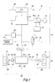
- Figure 1 is a schematic illustration of the pneumatic and electronic components of the present invention as utilized to control the inflation of groups of tires.
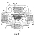
- Figure 2 is a section view of the quick release valve schematically illustrated in Figure 1.
- Figure 3 is a schematic illustration of an operator's control panel.
- In the following description of the present invention, certain terms will be utilized for purposes of reference only and are not intended to be limiting. The terms "upward", "downward", "rightward" and "leftward" refer to direction in the drawings to which reference is made. The terms "inward", and "outward", respectively, refer to directions towards and away from, respectively, the geometric center of the device described. The terms "inflation" and "deflation", respectively, refer to increased and decreased, respectively, pressurization of a tire or the like. Said terminology will include the words above specifically mentioned, derivatives thereof and words of similar import.
- The advantages of varying the inflation pressure of the pneumatic tires (especially the driven tires) of a vehicle, especially a relatively heavy duty vehicle, in accordance with the terrain over which the vehicle is traveling are well known in the prior art and may be appreciated by reference to above-mentioned U.S. Patent No. 4,640,331. Assuming, for example, the vehicle rear drive axle tires are normally inflated about about 75 psi (pounds per square inch) for highway operation, decreasing the tire inflation pressure to be 35 psi for cross country travel over rough road or to about 20-25 psi for operation in sand, mud or snow conditions or to about 10-12 psi for severe emergency conditions, will result in the tire having a greater contact area (i.e. footprint), and improved traction. In addition to improved traction at lower tire inflation pressure, the vehicle will be able to maintain a higher speed over poor ground, and reduce wear and tear on the vehicle, because of the smoother ride over "washboard" type terrain. Conversely, to reduce operating temperature and wear and tear on the tires at highway speed, a higher tire inflation pressure is desired. Of course, to increase mobility, it is highly desirable that the tire inflation pressures be controllable from the vehicle cab from an on-board source of pressurized fluid and be variable and maintainable with the vehicle in motion as well as when the vehicle is at rest.
- In an on-board CTIS system wherein the pressurization of certain tires, such as the tires on a particular axle or set of axles, is measured and controlled by periodically fluidly communicating the tire pressures with a common conduit during pressure measurement and control operations, it is desirable that the CTIS control have a method for detecting conditions indicative of one of the tires leaking or damaged beyond acceptable limits, to notify the vehicle operator of such condition and to modify the normal operating of the CTIS to prevent the tires from excessive loss of pressure. This is especially important in a CTIS wherein automatic pressure check/pressure adjustments, in the absence of a sensed leakage condition, occur only at relatively long intervals, such as once every fifteen minutes to once every thirty minutes. In such systems, it is important to verify, before the start of such extended period, that the wheel end valves are closed and that the tires are not damaged. This is especially true as, if a leakage condition exists, excessive pressure loss may occur during such extended period.
- The CTIS control method of the present invention is especially well suited for the type of
CTIS 10 schematically illustrated in Figure 1 and disclosed in above-mentioned U.S. Patent No. 4,640,331. CTIS 10 measures and controls the inflation pressure of the interior pressurizedchambers tires Tires - Each of the
inflatable chambers tires quick release valve 22 by means of a branch fluid passage, 24 and 26, respectively. The fluid passages each include a rotary seal assembly, 28 and 30, and a wheel-end valve assembly, 32 and 34. The rotary seal assemblies may be of any construction, such as seen in U.S. Patent No. 4,434, 833, the disclosure of which is incorporated by reference. - The
wheel end valves quick release valve 22 and are effective to be selectively opened to fluidly communicate the tire chambers andvalve 22.Wheel end valves conduits Wheel end valves - The structure and operational function of
valve 22 may be seen in greater detail by reference to Figure 2. Valve 22 includes avalve body 38 defining afirst port 40 connected tocommon conduit 20, asecond port 42 connected topassage 24, athird port 44 connected topassage 26 and afourth port 46 connected to avent passage 48 to atmosphere. Thevalve body 38 defines acentral cavity 50 in which a valve member such as plug-type diaphragm 52 is received. - The
outer periphery 54 ofdiaphragm 52 cooperates with anannular valve seat 56 to control the flow of fluid betweenport 40 and the fluidly communicatingports spring 58 andspring retainer 60 may be utilized to bias theouter periphery 54 into sealing contact with thevalve seat 56. Thecentral plug portion 62 cooperates with an annular valve seat 64 atport 46 to control the flow of fluid betweenports 46 and the fluidly communicatingports Diaphragm plug 62 is biased into sealing engagement with valve seat 64 by means of fluid pressure inconduit 20 acting onupper surface 66. The average pressure inpassages undersurface 68 of the diaphragm. - The operational characteristics of quick-
release valve 22 are that a fluid flow (i.e. flow of higher pressurized fluid to a conduit or chamber at a lower pressurization) may be maintained fromport 40 toports ports diaphragm 52 will lift to openports exhaust port 46. Further, thevalve 22, by establishing fluid communication fromport 40 toports conduits ports 42 and 44 (conduits 24 and 26) toexhaust port 46, is effective to equalize at the pressurization of the lower pressurized ofconduit 20 or average pressure ofconduits - It is important to note that quick-
release valve 22 through which the various valves at the wheel end assemblies are vented, is located remote from the wheel end assembly and may also be located remotely from the control valve and pressure transducer to be described below. - If a pressure differential exists between
tires conduit 20 is sealed, the pressure inconduit 20 will initially be the higher of the tire pressures and will decrease to an average of the tire pressures as the tires cross breath. - A
control valve assembly 70 is connected to a source of pressurized fluid, such as on-board compressor 72. Typically,compressor 72 will communicate with a vehicle air brakewet tank 74 which will supply theair brake system 76 with a higher priority than the CTIScontrol valve assembly 70. The control valve assembly is also connected to a vent passage 78 to atmosphere and to thecentral conduit 20. - The control valve assembly is effective to selectively vent
conduit 20 to atmosphere to ventpassages conduit 20 to a relatively high pressure for inflation of the tires, to pressurizeconduit 20 to a relatively low pressure to deflate the tires or topulse conduit 20 with a high pressure to allowconduit 20 to stabilize at the average pressure in the tire chambers. Preferably, if wheel end valves similar to those disclosed in above-mentioned U.S. Patent Nos. 4,640,331 or 4,678,017 are utilized, pressurization and venting ofconduit 20 is also effective to open and close, respectively, the wheel end valves. - A
pressure transducer 80 is provided for sensing the pressurization ofconduit 20 and for providing an output signal indicative thereof. To obtain an accurate measurement of average tire pressure,wheel end valves conduit 20 must be sealed atcontrol valve assembly 70 to allow the pressure inconduit 20 to attempt to stabilize at average tire pressure. - A second
central conduit 82 and a pair of two-way/two-position valves control valves assembly 70 andtransducer 80 to be utilized to measure and control a different set of tires. - A central processing unit (CPU) 88, preferably microprocessor based, may be provided for controlling
system 10.CPU 88 includesconditioning circuits 90 for receiving input signals, such as signals frompressure transducer 80,conditioning circuits 92 for issuing command output signals and logic (hardware or software) for defining logic rules by which the input signals are processed to generate command output signals. - At system start-up, or periodically during vehicle operation, it is desirable to have a system diagnostic routine or method to test for leakages which may require discounting the normal system operation and adopting a modified mode of operation until the condition is repaired.
- In operation,
CPU 88 is effective to cause an automatic periodic pressure check to determine if corrective action is required. Typically, in the absence of a sensed system fault or leakage condition, such pressure check operation will be commanded at a relatively long interval, such as every fifteen or thirty minutes, from the last pressure check/pressure check operation. If a tire leakage condition exists after obtaining a desired pressure and going to the steady state condition and is undetected, excessive tire deflation may occur during the steady state period between pressure checks. - Accordingly, during a pressure check/pressure modification operation, after desired pressure of the tires is verified and prior to entering into an extended steady-state operation, a verification checking routine is followed. The system is shut down (assumes period of steady-state or idle-state conditions) for a relatively short period of time, for example about thirty seconds. The system then performs a pressure measurement operation and compares the sensed inflation pressures just prior to and in the verification check. If pressure remains the same, or within prescribed limits, the lack of a leakage condition is verified, the CTIS assumes its steady-state condition and the CTIS will not automatically perform the next pressure check until expiration of the extended period of time. If a leakage condition is sensed, the operator will be informed of the condition and automatic pressure checking/pressure adjustment operations will occur at relatively short periods for example, to minimize the loss of pressure caused by the leakage condition.
- In one embodiment, the vehicle operator is provided with a
control panel 102, see Figure 3, having five illuminatable buttons, 104, 106, 108, 110 and 112, by which a desired tire pressurization may be selected. If the tire leak check indicates a leakage condition such as described above, the desired mode indication will flash indicating an inflate operation. If a leakage rate greater than can be compensated for byCTIS 10 is detected, all five buttons will flash and the system will remain shutdown. - As may be seen by reference to Figure 1,
CTIS 10 includes an at-axle portion orportions 114 and aremote portion 116 which may be located anywhere on the vehicle, preferably at a relatively protected location. Further, the at-axle portions 114 ofsystem 10 comprise astationary portion 118 androtating portions 120. - Although the preferred embodiments of the present invention have been described with a certain degree of particularity, it is understood, of course, that certain substitutions for and rearrangement of the parts may be resorted to without departing of the spirit and the scope of the present invention as hereinafter claimed.
Claims (7)
- Claim 1. A diagnostic method for sensing and reacting to conditions indicative of leakage of an inflatable tire (12/14), the pressurization of which tire is measured and controlled by an on-board CTIS (10), said CTIS automatically measuring inflation pressurization of said tire at predetermined extended time intervals and, in the absence a sensed system fault condition or pressure modification commands, assuming a steady-state condition during each of said extended intervals between automatic pressure measurements, said method characterized by:
At the completion of each automatic pressure measurement operation and pressure adjustment operation, after desired tire pressurization is sensed, assuming steady state conditions for a relatively short period of time, then performing a confirming pressure measurement to sense change in tire pressurement during said short period of time, and;
if the sensed change in tire pressurization is less than a reference value, allowing said CTIS to assume steady state conditions until expiration of said extended time interval; and
if the sensed change in tire pressurization is equal to or greater than said reference value, causing said CTIS to pressurize the tire to desired pressurization and to perform continuing automatic tire pressurization measurements after shortened time intervals of steady-state condition. - Claim 2. The method of claim 1 wherein said extended time intervals are at least ten times longer than said shortened time intervals.
- Claim 3. The method of claim 1 wherein said extended time intervals are at least twenty times greater than said shortened time intervals.
- Claim 4. The method of claim 1 wherein said extended time interval is at least ten minutes and said shortened time interval is less than thirty seconds.
- Claim 5. The method of claim 1 further characterized by signaling the pressure of a tire leakage condition if said sensed change in tire pressurization is equal to or greater than said reference value.
- Claim 6. The method of claim 1 wherein said reference value is generally equal to the expected change in pressure of said inflatable tire during said shortened period time under failure of wheel-end valve to close conditions.
- Claim 7. The method of claim 1 wherein said shortened period of time is generally equal to said shortened time interval.
Priority Applications (1)
| Application Number | Priority Date | Filing Date | Title |
|---|---|---|---|
| AT89305336T ATE93778T1 (en) | 1988-05-25 | 1989-05-25 | TIRE LEAK DETECTION PROCEDURE FOR CENTER TIRE INFLATION SYSTEMS. |
Applications Claiming Priority (2)
| Application Number | Priority Date | Filing Date | Title |
|---|---|---|---|
| US07/198,404 US4860579A (en) | 1988-05-25 | 1988-05-25 | Tire leakage detection method for central tire inflation system |
| US198404 | 1994-02-22 |
Publications (3)
| Publication Number | Publication Date |
|---|---|
| EP0344003A2 true EP0344003A2 (en) | 1989-11-29 |
| EP0344003A3 EP0344003A3 (en) | 1990-06-20 |
| EP0344003B1 EP0344003B1 (en) | 1993-09-01 |
Family
ID=22733238
Family Applications (1)
| Application Number | Title | Priority Date | Filing Date |
|---|---|---|---|
| EP89305336A Expired - Lifetime EP0344003B1 (en) | 1988-05-25 | 1989-05-25 | Tire leakage detection method for central tire inflation system |
Country Status (11)
| Country | Link |
|---|---|
| US (1) | US4860579A (en) |
| EP (1) | EP0344003B1 (en) |
| JP (1) | JPH0220410A (en) |
| KR (1) | KR900017817A (en) |
| AT (1) | ATE93778T1 (en) |
| BR (1) | BR8902874A (en) |
| CA (1) | CA1312364C (en) |
| DE (1) | DE68908772T2 (en) |
| ES (1) | ES2043014T3 (en) |
| IL (1) | IL90262A (en) |
| ZA (1) | ZA893938B (en) |
Cited By (2)
| Publication number | Priority date | Publication date | Assignee | Title |
|---|---|---|---|---|
| WO1992014620A2 (en) * | 1991-02-21 | 1992-09-03 | Ttc/Truck Tech Corp. | Tire monitoring apparatus and method |
| US5473938A (en) * | 1993-08-03 | 1995-12-12 | Mclaughlin Electronics | Method and system for monitoring a parameter of a vehicle tire |
Families Citing this family (32)
| Publication number | Priority date | Publication date | Assignee | Title |
|---|---|---|---|---|
| US5327346A (en) * | 1991-08-23 | 1994-07-05 | Harsco Corporation | Automatic control for central tire inflation system |
| US5263524A (en) * | 1992-12-28 | 1993-11-23 | Eaton Corporation | Trailer detection control for vehicle central tire inflation system |
| US5819806A (en) * | 1993-12-29 | 1998-10-13 | Daikyo Co., Ltd. | Channel housing with curving channels, and a manufacturing method therefor |
| US5540092A (en) | 1994-10-31 | 1996-07-30 | Handfield; Michael | System and method for monitoring a pneumatic tire |
| US5553647A (en) * | 1994-12-14 | 1996-09-10 | Hayes Wheels International, Inc. | Central tire inflation system |
| US6250327B1 (en) | 1999-02-25 | 2001-06-26 | Dana Corporation | Fluid flow valve with variable flow rate |
| US6894607B1 (en) * | 2001-12-03 | 2005-05-17 | Dana Corporation | Tire pressure management system valve integrity verification method |
| US6604414B1 (en) | 2001-12-04 | 2003-08-12 | Dana Corporation | Supply and tire pressure sensing apparatus and method |
| US6868719B1 (en) | 2001-12-04 | 2005-03-22 | Dana Corporation | Tire pressure monitoring method |
| US6561017B1 (en) | 2001-12-04 | 2003-05-13 | Dana Corporation | Tire inflation method |
| US6666078B1 (en) | 2001-12-04 | 2003-12-23 | Dana Corporation | Target tire pressure learning method |
| US6758088B2 (en) * | 2002-04-22 | 2004-07-06 | Dana Corporation | Active adaptation of control algorithms for a central tire inflation system |
| US20040173296A1 (en) * | 2003-03-06 | 2004-09-09 | White Jay D. | Tire inflation system apparatus and method |
| US7273082B2 (en) * | 2004-03-05 | 2007-09-25 | Hendrickson Usa, L.L.C. | Tire inflation system apparatus and method |
| US7201066B1 (en) | 2005-03-30 | 2007-04-10 | The Board Of Regents For Oklahoma State University | System for automatic tire inflation |
| US7896045B2 (en) * | 2006-11-13 | 2011-03-01 | The Board Of Regents For Oklahoma State University | Apparatus for delivering air through powered axle assemblies |
| US8931534B2 (en) * | 2010-03-10 | 2015-01-13 | Accuride Corporation | Vehicle wheel assemblies and valves for use with a central tire inflation system |
| NZ603711A (en) | 2010-07-30 | 2014-12-24 | Hendrickson Usa Llc | Tire inflation system with discrete deflation circuit |
| US9434216B2 (en) | 2010-07-30 | 2016-09-06 | Hendrickson Usa, L.L.C. | Tire inflation system with discrete deflation circuit |
| ES2686556T3 (en) | 2010-11-19 | 2018-10-18 | Equalaire Systems, Inc. | Tire management system |
| WO2014071220A2 (en) | 2012-11-01 | 2014-05-08 | FlowBelow Aero, Inc. | Aerodynamic system and adjustable fairings |
| US9493042B2 (en) * | 2013-03-15 | 2016-11-15 | Dana Heavy Vehicle Systems Group, Llc | Method of venting a tire inflation system and control unit utilized therein |
| US9597931B2 (en) | 2013-10-11 | 2017-03-21 | Arvinmeritor Technology, Llc | Tire inflation system and method of control |
| EP2851218A1 (en) * | 2013-09-18 | 2015-03-25 | ArvinMeritor Technology, LLC | Tire inflation system having a pressure equalization valve assembly |
| US9409450B2 (en) | 2013-10-11 | 2016-08-09 | Arvinmeritor Technology, Llc | Tire inflation system and method of control |
| GB2540417B (en) * | 2015-07-17 | 2019-04-10 | Jaguar Land Rover Ltd | Central tyre inflation system |
| DE102016203685A1 (en) | 2016-03-07 | 2017-09-07 | Deere & Company | System for tire pressure monitoring for a commercial vehicle |
| WO2018085791A1 (en) | 2016-11-04 | 2018-05-11 | FlowBelow Aero, Inc. | Chassis mounted energy extraction and delivery system |
| US10654529B2 (en) | 2017-06-24 | 2020-05-19 | FlowBelow Aero, Inc. | Aerodynamic systems and fairings with fairing caps |
| WO2019014503A1 (en) | 2017-07-12 | 2019-01-17 | FlowBelow Aero, Inc. | Aerodynamic toolbox assembly |
| US10882571B2 (en) | 2017-07-30 | 2021-01-05 | FlowBelow Aero, Inc. | Rotatable aerodynamic fairing system |
| US11767064B2 (en) | 2021-01-12 | 2023-09-26 | FlowBelow Aero, Inc. | Spring-biased mud flap hanger with improved pivoting motion guidance |
Citations (6)
| Publication number | Priority date | Publication date | Assignee | Title |
|---|---|---|---|---|
| DE3308080A1 (en) * | 1983-03-08 | 1984-09-20 | Robert Bosch Gmbh, 7000 Stuttgart | Device for matching tyre pressure and vehicle speed to one another |
| US4574267A (en) * | 1982-05-06 | 1986-03-04 | Trw Inc. | Tire pressure warning system |
| EP0221522A2 (en) * | 1985-11-07 | 1987-05-13 | Uniroyal Englebert Reifen GmbH | Variable air-pressure value determination method for a vehicle air tyre, as well as a pressure value indication method |
| US4763709A (en) * | 1986-07-03 | 1988-08-16 | Teledyne Industries Inc. | Tire inflation system |
| US4782878A (en) * | 1986-12-18 | 1988-11-08 | Tire Inflation Systems, Corp. | Tire inflating and deflating system and apparatus |
| EP0297837A2 (en) * | 1987-06-29 | 1989-01-04 | Eaton Corporation | Central tire inflation system |
Family Cites Families (4)
| Publication number | Priority date | Publication date | Assignee | Title |
|---|---|---|---|---|
| US3276503A (en) * | 1965-01-21 | 1966-10-04 | Scovill Manufacturing Co | Tire pressure maintenance system |
| US4487154A (en) * | 1982-10-15 | 1984-12-11 | Rockcor, Inc. | Pressure-activated low pressure warning device |
| US4678017A (en) * | 1984-06-04 | 1987-07-07 | Eaton Corporation | Wheel end valve for central tire inflation system |
| US4640331A (en) * | 1984-06-04 | 1987-02-03 | Eaton Corporation | Central tire inflation system |
-
1988
- 1988-05-25 US US07/198,404 patent/US4860579A/en not_active Expired - Lifetime
-
1989
- 1989-05-05 CA CA000598888A patent/CA1312364C/en not_active Expired - Fee Related
- 1989-05-11 IL IL90262A patent/IL90262A/en not_active IP Right Cessation
- 1989-05-24 BR BR898902874A patent/BR8902874A/en not_active IP Right Cessation
- 1989-05-24 ZA ZA893938A patent/ZA893938B/en unknown
- 1989-05-25 JP JP1132510A patent/JPH0220410A/en active Pending
- 1989-05-25 ES ES89305336T patent/ES2043014T3/en not_active Expired - Lifetime
- 1989-05-25 AT AT89305336T patent/ATE93778T1/en active
- 1989-05-25 KR KR1019890007000A patent/KR900017817A/en not_active Application Discontinuation
- 1989-05-25 EP EP89305336A patent/EP0344003B1/en not_active Expired - Lifetime
- 1989-05-25 DE DE89305336T patent/DE68908772T2/en not_active Expired - Fee Related
Patent Citations (6)
| Publication number | Priority date | Publication date | Assignee | Title |
|---|---|---|---|---|
| US4574267A (en) * | 1982-05-06 | 1986-03-04 | Trw Inc. | Tire pressure warning system |
| DE3308080A1 (en) * | 1983-03-08 | 1984-09-20 | Robert Bosch Gmbh, 7000 Stuttgart | Device for matching tyre pressure and vehicle speed to one another |
| EP0221522A2 (en) * | 1985-11-07 | 1987-05-13 | Uniroyal Englebert Reifen GmbH | Variable air-pressure value determination method for a vehicle air tyre, as well as a pressure value indication method |
| US4763709A (en) * | 1986-07-03 | 1988-08-16 | Teledyne Industries Inc. | Tire inflation system |
| US4782878A (en) * | 1986-12-18 | 1988-11-08 | Tire Inflation Systems, Corp. | Tire inflating and deflating system and apparatus |
| EP0297837A2 (en) * | 1987-06-29 | 1989-01-04 | Eaton Corporation | Central tire inflation system |
Cited By (7)
| Publication number | Priority date | Publication date | Assignee | Title |
|---|---|---|---|---|
| WO1992014620A2 (en) * | 1991-02-21 | 1992-09-03 | Ttc/Truck Tech Corp. | Tire monitoring apparatus and method |
| WO1992014620A3 (en) * | 1991-02-21 | 1992-12-10 | Tcc Truck Tech Corp | Tire monitoring apparatus and method |
| US5231872A (en) * | 1991-02-21 | 1993-08-03 | Ttc/Truck Tech Corp. | Tire monitoring apparatus and method |
| US5335540A (en) * | 1991-02-21 | 1994-08-09 | Ttc Truck Tech Corp. | Tire monitoring apparatus and method |
| US5473938A (en) * | 1993-08-03 | 1995-12-12 | Mclaughlin Electronics | Method and system for monitoring a parameter of a vehicle tire |
| US5663496A (en) * | 1993-08-03 | 1997-09-02 | The Mclaughlin Group | Tire monitoring via an electromagnetic path including the ground plan of a vehicle |
| US5741966A (en) * | 1993-08-03 | 1998-04-21 | Handfield; Michael | Method and system for monitoring a parameter of a vehicle tire |
Also Published As
| Publication number | Publication date |
|---|---|
| BR8902874A (en) | 1990-02-01 |
| ATE93778T1 (en) | 1993-09-15 |
| EP0344003B1 (en) | 1993-09-01 |
| EP0344003A3 (en) | 1990-06-20 |
| ZA893938B (en) | 1990-02-28 |
| JPH0220410A (en) | 1990-01-24 |
| DE68908772D1 (en) | 1993-10-07 |
| KR900017817A (en) | 1990-12-20 |
| IL90262A (en) | 1991-08-16 |
| US4860579A (en) | 1989-08-29 |
| DE68908772T2 (en) | 1993-12-23 |
| CA1312364C (en) | 1993-01-05 |
| ES2043014T3 (en) | 1993-12-16 |
| IL90262A0 (en) | 1989-12-15 |
Similar Documents
| Publication | Publication Date | Title |
|---|---|---|
| US4860579A (en) | Tire leakage detection method for central tire inflation system | |
| US5249609A (en) | Deflation control system and method | |
| US5121774A (en) | Fault detection method | |
| US5179981A (en) | Fault detection method for central tire inflation system | |
| CA1335830C (en) | Ctis control system and method for sensing and indication of inadequate rate of change of tire inflation pressurization | |
| US4678017A (en) | Wheel end valve for central tire inflation system | |
| US4754792A (en) | Tire valve assembly for central tire inflation system | |
| CA1333929C (en) | Deflation control system and method | |
| EP2064075B1 (en) | A tire inflation method | |
| CA1240244A (en) | Central tire inflation system | |
| US5313995A (en) | Central tire inflation system | |
| CA2483029C (en) | Active adaptation of control algorithms for a central tire inflation system | |
| EP0368365B1 (en) | Central tire inflation system | |
| EP0164916B1 (en) | Central tire inflation system | |
| EP0343990A2 (en) | Tire leak detection method for central tire inflation system | |
| CA1338384C (en) | Fault detection method for central tire inflation system |
Legal Events
| Date | Code | Title | Description |
|---|---|---|---|
| PUAI | Public reference made under article 153(3) epc to a published international application that has entered the european phase |
Free format text: ORIGINAL CODE: 0009012 |
|
| AK | Designated contracting states |
Kind code of ref document: A2 Designated state(s): AT CH DE ES FR GB IT LI NL SE |
|
| PUAL | Search report despatched |
Free format text: ORIGINAL CODE: 0009013 |
|
| AK | Designated contracting states |
Kind code of ref document: A3 Designated state(s): AT CH DE ES FR GB IT LI NL SE |
|
| 17P | Request for examination filed |
Effective date: 19900926 |
|
| 17Q | First examination report despatched |
Effective date: 19920429 |
|
| GRAA | (expected) grant |
Free format text: ORIGINAL CODE: 0009210 |
|
| AK | Designated contracting states |
Kind code of ref document: B1 Designated state(s): AT CH DE ES FR GB IT LI NL SE |
|
| REF | Corresponds to: |
Ref document number: 93778 Country of ref document: AT Date of ref document: 19930915 Kind code of ref document: T |
|
| ITF | It: translation for a ep patent filed |
Owner name: ING. C. GREGORJ S.P.A. |
|
| REF | Corresponds to: |
Ref document number: 68908772 Country of ref document: DE Date of ref document: 19931007 |
|
| ET | Fr: translation filed | ||
| REG | Reference to a national code |
Ref country code: ES Ref legal event code: FG2A Ref document number: 2043014 Country of ref document: ES Kind code of ref document: T3 |
|
| PLBE | No opposition filed within time limit |
Free format text: ORIGINAL CODE: 0009261 |
|
| STAA | Information on the status of an ep patent application or granted ep patent |
Free format text: STATUS: NO OPPOSITION FILED WITHIN TIME LIMIT |
|
| 26N | No opposition filed | ||
| EAL | Se: european patent in force in sweden |
Ref document number: 89305336.3 |
|
| PGFP | Annual fee paid to national office [announced via postgrant information from national office to epo] |
Ref country code: AT Payment date: 19950421 Year of fee payment: 7 |
|
| PGFP | Annual fee paid to national office [announced via postgrant information from national office to epo] |
Ref country code: SE Payment date: 19950424 Year of fee payment: 7 |
|
| PGFP | Annual fee paid to national office [announced via postgrant information from national office to epo] |
Ref country code: ES Payment date: 19950517 Year of fee payment: 7 |
|
| PGFP | Annual fee paid to national office [announced via postgrant information from national office to epo] |
Ref country code: NL Payment date: 19950531 Year of fee payment: 7 |
|
| PGFP | Annual fee paid to national office [announced via postgrant information from national office to epo] |
Ref country code: CH Payment date: 19950620 Year of fee payment: 7 |
|
| PG25 | Lapsed in a contracting state [announced via postgrant information from national office to epo] |
Ref country code: AT Effective date: 19960525 |
|
| PG25 | Lapsed in a contracting state [announced via postgrant information from national office to epo] |
Ref country code: SE Effective date: 19960526 |
|
| PG25 | Lapsed in a contracting state [announced via postgrant information from national office to epo] |
Ref country code: ES Free format text: LAPSE BECAUSE OF NON-PAYMENT OF DUE FEES Effective date: 19960527 |
|
| PG25 | Lapsed in a contracting state [announced via postgrant information from national office to epo] |
Ref country code: LI Effective date: 19960531 Ref country code: CH Effective date: 19960531 |
|
| PG25 | Lapsed in a contracting state [announced via postgrant information from national office to epo] |
Ref country code: NL Effective date: 19961201 |
|
| REG | Reference to a national code |
Ref country code: CH Ref legal event code: PL |
|
| EUG | Se: european patent has lapsed |
Ref document number: 89305336.3 |
|
| NLV4 | Nl: lapsed or anulled due to non-payment of the annual fee |
Effective date: 19961201 |
|
| PGFP | Annual fee paid to national office [announced via postgrant information from national office to epo] |
Ref country code: GB Payment date: 19970408 Year of fee payment: 9 |
|
| PGFP | Annual fee paid to national office [announced via postgrant information from national office to epo] |
Ref country code: FR Payment date: 19970512 Year of fee payment: 9 |
|
| PGFP | Annual fee paid to national office [announced via postgrant information from national office to epo] |
Ref country code: DE Payment date: 19970528 Year of fee payment: 9 |
|
| PG25 | Lapsed in a contracting state [announced via postgrant information from national office to epo] |
Ref country code: GB Free format text: LAPSE BECAUSE OF NON-PAYMENT OF DUE FEES Effective date: 19980525 |
|
| PG25 | Lapsed in a contracting state [announced via postgrant information from national office to epo] |
Ref country code: FR Free format text: LAPSE BECAUSE OF NON-PAYMENT OF DUE FEES Effective date: 19980531 |
|
| GBPC | Gb: european patent ceased through non-payment of renewal fee |
Effective date: 19980525 |
|
| PG25 | Lapsed in a contracting state [announced via postgrant information from national office to epo] |
Ref country code: DE Free format text: LAPSE BECAUSE OF NON-PAYMENT OF DUE FEES Effective date: 19990302 |
|
| REG | Reference to a national code |
Ref country code: FR Ref legal event code: ST |
|
| REG | Reference to a national code |
Ref country code: ES Ref legal event code: FD2A Effective date: 19990503 |
|
| PG25 | Lapsed in a contracting state [announced via postgrant information from national office to epo] |
Ref country code: IT Free format text: LAPSE BECAUSE OF NON-PAYMENT OF DUE FEES;WARNING: LAPSES OF ITALIAN PATENTS WITH EFFECTIVE DATE BEFORE 2007 MAY HAVE OCCURRED AT ANY TIME BEFORE 2007. THE CORRECT EFFECTIVE DATE MAY BE DIFFERENT FROM THE ONE RECORDED. Effective date: 20050525 |