EP0345051A2 - Balloon dilation catheter - Google Patents
Balloon dilation catheter Download PDFInfo
- Publication number
- EP0345051A2 EP0345051A2 EP89305503A EP89305503A EP0345051A2 EP 0345051 A2 EP0345051 A2 EP 0345051A2 EP 89305503 A EP89305503 A EP 89305503A EP 89305503 A EP89305503 A EP 89305503A EP 0345051 A2 EP0345051 A2 EP 0345051A2
- Authority
- EP
- European Patent Office
- Prior art keywords
- catheter
- balloon
- sheath
- shaft
- dilation
- Prior art date
- Legal status (The legal status is an assumption and is not a legal conclusion. Google has not performed a legal analysis and makes no representation as to the accuracy of the status listed.)
- Ceased
Links
Images


Classifications
-
- A—HUMAN NECESSITIES
- A61—MEDICAL OR VETERINARY SCIENCE; HYGIENE
- A61M—DEVICES FOR INTRODUCING MEDIA INTO, OR ONTO, THE BODY; DEVICES FOR TRANSDUCING BODY MEDIA OR FOR TAKING MEDIA FROM THE BODY; DEVICES FOR PRODUCING OR ENDING SLEEP OR STUPOR
- A61M29/00—Dilators with or without means for introducing media, e.g. remedies
- A61M29/02—Dilators made of swellable material
-
- A—HUMAN NECESSITIES
- A61—MEDICAL OR VETERINARY SCIENCE; HYGIENE
- A61M—DEVICES FOR INTRODUCING MEDIA INTO, OR ONTO, THE BODY; DEVICES FOR TRANSDUCING BODY MEDIA OR FOR TAKING MEDIA FROM THE BODY; DEVICES FOR PRODUCING OR ENDING SLEEP OR STUPOR
- A61M25/00—Catheters; Hollow probes
- A61M2025/0004—Catheters; Hollow probes having two or more concentrically arranged tubes for forming a concentric catheter system
-
- A—HUMAN NECESSITIES
- A61—MEDICAL OR VETERINARY SCIENCE; HYGIENE
- A61M—DEVICES FOR INTRODUCING MEDIA INTO, OR ONTO, THE BODY; DEVICES FOR TRANSDUCING BODY MEDIA OR FOR TAKING MEDIA FROM THE BODY; DEVICES FOR PRODUCING OR ENDING SLEEP OR STUPOR
- A61M25/00—Catheters; Hollow probes
- A61M25/10—Balloon catheters
- A61M2025/1043—Balloon catheters with special features or adapted for special applications
- A61M2025/1072—Balloon catheters with special features or adapted for special applications having balloons with two or more compartments
Definitions
- the present invention relates generally to the field of catheters. More specifically, the present invention relates to catheters which are adapted to be inserted into the urethral lumen to alleviate obstructive prostatism, a condition quite common in males over the age of 50.
- the prostate is a somewhat pear-shaped gland that extends around the urethral lumen from the neck of the bladder to the pelvic floor. Because of the close relationship of the prostate to the urethra, enlargement of the prostate, usually referred to as hypertrophy or hyperplasia, may fairly quickly obstruct the urethra, particularly if the hyperplasia occurs close to the lumen. Such an obstruction inhibits normal micturition, which causes an accumulation of urine in the bladder.
- the surgical treatment of hyperplasia of the prostate gland has been a routine procedure in the operating room for many years.
- One method of surgical treatment is open prostatectomy whereby an incision is made to expose the enlarged prostate gland and remove the hypertrophied tissue under direct vision.
- Another method of treating obstructive prostatism is a technique known as transurethral resection.
- an instrument called a resectoscope is placed into the external opening of the urethra and an electrosurgical loop is used to carve away sections of the prostate gland from within the prostatic urethra under endoscopic vision.
- transurethral resection offers many benefits to the patient as compared to open prostatectomy.
- the trained urologist can remove the hypertrophied prostate with less patient discomfort, a shorter hospital stay and lower rates of mortality and morbidity.
- U.S. Patent No. 4,432,757 to Davis, Jr. teaches the use of an indwelling urethral catheter assembly, having a Foley-type balloon disposed near the distal end thereof and a substantially non-compliant balloon lead shaft proximate to the Foley-type balloon.
- the device is adapted to be inserted through the urethra up into the bladder.
- the Foley-type balloon and the balloon lead shaft are then inflated, although the balloon lead shaft remains relatively non-compliant and therefore does not expand appreciably.
- Gentle traction is then applied to a catheter sleeve head to sever the sleeve from the remainder of the catheter, leaving the balloon lead shaft in position within the urethra.
- Another method of treating hypertrophy of the prostate gland without the need for surgery has been to inject medications into the prostate gland by means of a catheter.
- a catheter Such a device is disclosed in U.S. Patent No. 550,238 to Allen, wherein two balloons are disposed along two sections of a catheter, and inflated to isolate an area within the urethra prior to the injection of the medication.
- these injections are frequently ineffective as the prostate gland exhibits only a limited ability to absorb the injected antibiotics, and proper positioning and retaining of the catheter with respect to the affected area is extremely difficult.
- Klein U.S. Patent No. 4,660,560.
- a calibrating catheter is used to measure the distance between the neck of the bladder and the bottom of the prostate gland.
- a dilatation catheter having an annular balloon with a length equivalent to the measured length, and a Foley-type balloon at the distal end thereof is then inserted into the urethra until the Foley-type balloon is within the bladder.
- the Foley balloon is then inflated in the bladder and is used to position the dilatation balloon in the prostate.
- the latter balloon is then inflated, to force the prostate away from the urethral lumen.
- Use of the Klein catheter can effectively eliminate uncertainty regarding positioning of the upper (distal) end of the dilatation balloon, thereby significantly facilitating the treatment of prostatic hypertrophy.
- the calibration catheter is used to measure the length of the affected prostate, it is withdrawn from the urethra, and the dilatation catheter is then inserted.
- Proper insertion of the dilatation catheter is crucial, as stretching of the external urethral sphincter muscle, which lies just below the prostate, could cause incontinence.
- the catheter is too large to fit through a conventional cystoscope sheath.
- bleeding which is common during such a procedure, not infrequently obscures the field of view of a cystoscope lens, making it useless.
- the present invention provides a dilatation catheter and sheath of novel design for use as a non-surgical alternative to the treatment of the symptoms of obstructive prostatism.
- the sheath for the catheter of the present invention is uniquely sized and shaped so as to provide a path through which the catheter may travel, and leaves sufficient room for a standard cystoscopic lens.
- the sheath is elliptically shaped so as to minimize the circumference thereof.
- the proximal end of the dilatation balloon is marked with a heavy line which may be viewed by the urologist through the lens.
- an irrigation conduit is provided in the catheter. Saline or other irrigating solution is allowed to flow through the irrigation conduit, to an area proximate the line at the proximal end of the dilatation balloon. The saline solution flushes the blood associated with the procedure away from the lens, so that the urologist's view is no longer obstructed.
- a significant feature of the dilatation catheter of the present invention is the unique, squared-off configuration of either or both end of the dilatation balloon. This feature enables dilatation of the affected prostatic urethra, in close proximity to the bladder and/or external urethral spincter muscle without inadvertent dilatation of these structures.
- the dilatation balloon of the present invention is made from a material which has a high tensile strength, rated at between 20,000 to 50,000 psi., and although somewhat stiff, is of a sufficiently small thickness so as to provide a catheter which is of substantially the same size and shape of that of the unstretched lumen.
- the sheath is provided with a flexible tip which readily deforms to accommodate the sharp edges which may form when the dilatation balloon is deflated.
- the sheath also performs the function of evacuating the irrigation fluid from the urethral lumen during the irrigation process.
- Yet another key feature of the present invention is the ability to yield optimal dilatation of the prostate, even at the proximal and distal edges of the affected prostatic urethra. This is accomplished by subjecting the balloon material to elevated temperatures, controlled internal pressures and axial tension during the molding process, which stretch the balloon both axially and radially to form a balloon having a somewhat squared configuration at one or both ends.
- an intraurethral dilatation device for relieving the symptoms of obstructive prostatism which is adapted for easy insertion into the urethra for pressure dilatation of the prostate, so as to force the prostate away from the urethral lumen and thereby eliminate the obstruction.
- the dilatation device includes an introduction sheath, suitable for housing a catheter and a cystoscope lens; a catheter shaft having a plurality of lumen therethrough; an expansible locating balloon, disposed near the distal tip of the catheter which, when inflated within the bladder, will provide an anchor with the bladder neck; and a dilatation balloon, proximate the locating balloon which, when inflated, conforms to a preselected configuration, so as to radially outwardly dilate the obstruction away from the urethral lumen.
- the means for inflating the dilatation catheter is provided with a clipping mechanism which is adapted to receive a portion of the sheath, and enable the urologist to perform the procedure without assistance.
- the clip is situated on the inflation device such that the urologist may view the location of the dilatation balloon through the endoscopic lens with one eye and at the same time monitor the pressure gauge with the other eye.
- the sheath 12 is advantageously a substantially rigid, axially elongate hollow shaft throughout most of its length, but having a flexible distal tip 14.
- the sheath 12 exhibits an inner surface 16 which is substantially ellipsoid in cross-section, and is adapted to receive and guide an axially elongate catheter 18 and an endoscope 20 longitudinally therethrough.
- the particular endoscope used is known as a cystoscope.
- a U-shaped clip 28 is integrally connected to the top of an inflation device 30 and is adapted to removably receive and retain the cylindrical housing 22 so as to enable the device 10 to be operated by one person, without the need for assistance.
- the removable attachment of the sheath 12 to the U-shaped clip 28 is illustrated in Figure 2.
- a C-shaped clip 32 may also be provided on the body of the inflation device 30, to removably receive and retain the catheter 18 therein and provide additional support for the proximal end of the device, thus controlling the catheter so it does not interfere with the eyepiece of the endoscope.
- a drainage port 38 Situated on the underside 36 of the cylindrical housing 22 is a drainage port 38, having a cock valve 40 secured therein.
- the cock valve 40 is adapted to allow back-flowing fluids to escape the sheath 12 when positioned in the "on” position, and to prohibit the release of such fluids when in the "off" position.
- the cylindrical housing 22 includes a hub portion 42, disposed at the proximal end thereof.
- a rubberized septum 44 preferably formed from a silicon rubber compound, is detachably placed onto the hub 42 of the cylindrical housing 22 so as to provide a seal therefor.
- the septum 44 is a circular cap 46, having a pair of boot sleeves 48, 50 integrally connected to the proximal end of the cap 46.
- the septum 44 exhibits an outwardly extending boot sleeve 48 an inwardly extending boot sleeve 50.
- the boot sleeves 48, 50 are adapted to receive the cystoscope lens 20 and the dilatation catheter 18, and provide the septum 44 with elasticity at the point of contact therebetween.
- both of the boot sleeves 52, 54 extend outwardly from the septum cap 44. This embodiment is possible only when there exists sufficient room on the outside of the septum, such that a sharing of a common wall between the two sleeves is not necessitated.
- the dilatation catheter 18 of the present invention comprises an axially elongate catheter shaft 56, having a tapered guiding end 58, and a plurality of parallel conduits disposed therein. Situated near the guiding end 58 of the catheter shaft 56 is a locating balloon 60.
- the locating balloon 60 is a small latex Foley-type balloon, adapted for inflation by a source of pressurized fluid. Adjacent the locating balloon 60 is a larger dilatation balloon 62, having a proximal shoulder 64 and a distal shoulder 66.
- a feature of this invention is that the distal shoulder 66 of the dilatation balloon 62 is overlapped by a portion of the locating balloon 60, such that, when the balloons are expanded, a minimal valley is left between the two balloons.
- Both of the balloons 60, 62 are bonded to the outer perimeter of the catheter shaft 56 by suitable adhesive or thermal process.
- the dilatation balloon 62 can be molded with a steep, squared off end 74, as illustrated in Figure 13.
- a material which is well adapted to construction of the dilatation balloon 62 of the present invention is polyethylene terephthalate (PET), such as KODAK's 9921.
- PET polyethylene terephthalate
- the balloon 62 is extruded in a straight pipe configuration and then stretched and blown under high temperature and pressure to yield the desired shape 74.
- This type of technique is commonly applied in the making of angioplasty balloons.
- the PET material used to construct the dilatation balloon exhibits superior tensile strength characteristics to that of materials used in manufacturing other types of dilatation balloons, for example older angioplasty balloons.
- the PET material used to construct the dilatation balloon of the present invention has a tensile strength of between 20,000 to 50,000 psi, and is rated to withstand at least 3 atmospheres of pressure, and as much as 5 atm.
- the walls of the balloon would necessarily be much thicker in order to withstand the exceedingly high pressures required for adequate dilatation of the affected prostatic urethra.
- the PET material by virtue of its superior strength, allows a thinner balloon to be utilized.
- the thinness of the balloon thus formed makes possible a dilatation balloon 62 which, in an uninflated state, conforms to the external walls of the catheter shaft 56, thereby providing a dilatation catheter 18 having substantially the same size and shape as the unstretched lumen.
- the increased strength of the material also dictates a balloon which is somewhat stiff and substantially less pliable than a latex balloon.
- the distal tip 14 of the introduction sheath 12 is formed of a flexible material, which readily deforms to the gross contours of the deflated dilatation balloon 62, so as to coerce the balloon 62 into the introduction sheath 12 prior to the withdrawal of the catheter 18 from the urethra.
- the tip 14 is formed from a substantially malleable Poly Vinyl Chloride (PVC) compound, which is RF welded to rigid shaft portion 12 of the sheath.
- PVC Poly Vinyl Chloride
- visual indicia such as the marking 78 on the exterior shaft 56 of the catheter 18 is provided.
- the indicia 78 will be advanced out of the sheath 12.
- the catheter 18 is fully retracted within the sheath 12, and the device 10 may be withdrawn, without causing undue trauma to the urethral lumen.
- the catheter shaft 56 houses a pair of circular inflation conduits 80, 82 and an irrigation conduit 84.
- the inflation conduit 80 having an aperture 86 underlying the locating balloon 60 exhibits a tubular passageway which permits pressurized fluid to be transmitted into the chamber enclosed by the locating balloon 60 , so as to selectively inflate the balloon 60 to a suitable level.
- the inflation conduit 82 having a pair of inflation apertures 90, 92 underlying the dilatation balloon 62 allows pressurized fluid to selectively fill the balloon 62 to a desired level.
- a simple fluid valve 94 may be connected to the proximal end of the conduit 80.
- This valve 94 is integrally connected to the inflation conduit 80 and may be easily manipulated to allow quick sealing of the conduit 80 and maintain the pressurized fluid within the balloon chamber 60 and the conduit 80.
- the locating balloon 60 may be pressurized by inserting a hypodermic syringe (not shown) into the valve 94, with the valve 94 in its open condition. By forcing fluid into the conduit 80, the locating balloon 60, at the distal end of the inflation conduit will be inflated. The valve 94 may then be closed, and the hypodermic syringe removed, leaving the locating balloon 60 in an inflated state.
- the source of pressurized fluid 98 used to inflate the dilatation balloon 62 is connected to a pressure gauge 100.
- the inflation device 98 includes a syringe barrel 102 having a threaded rod and ratchet mechanism 104 which replaces the conventional plunger. This configuration allows fine tuning of the pressure amassed within the dilatation balloon 62 by screw turning the threaded rod 104. It has been determined that an intra-balloon pressure of approximately 3 atm., or 45 p.s.i.g. is sufficient to force the prostate away from the urethral lumen to relieve the obstruction and reestablish normal micturition.
- a heavy black line 106 Proximate to the proximal end of the dilatation balloon 62, and encircling the proximal shoulder 64 thereof, is a heavy black line 106.
- an important feature of this invention is the provision of an irrigation system.
- the system provides the dual features of both flushing blood away from the lens of the cystoscope to aid in the viewing of the external sphincter muscle and the black line 106 on the shoulder 64 of the dilatation balloon 62 and inhibiting coagulation of blood within the urethra.
- This flushing system includes a plurality of irrigation ports 110 disposed along the exterior shaft 56 of the catheter 18, proximate to the line 106 are provided.
- the irrigation ports 110 are adapted to continuously flush fluid, for example, saline, from the irrigation conduit 84, which extends through the center of the catheter shaft 56.
- the irrigation conduit 84 is provided with a coupling device 112 at the proximal end thereof, adapted to receive a source of flushing fluid, which, for example, can be a hanging container of saline (not shown), having a length of flexible tubing extending therefrom, for connection to the coupling device 112.
- the source of fluid is elevated and allowed to flow by gravity through the irrigation conduit 84 and out the irrigation ports 110, so as to flush blood away from the lens 20 and allow the urologist an unobstructed view of the external sphincter muscle 108 and the line 106 encircling the proximal shoulder 64 of the dilatation balloon 62.
- the flushing of blood inhibits coagulation, and therefore substantially eliminates clotting within the urethral lumen.
- Back-flowing flushing fluid and blood is drained from the urethra through introduction sheath 12 by gravity flow.
- a drainage reservoir (not shown) is connected to the cock valve 40 which, when in its open position, allows the back-flowing fluids to drain, by gravity flow, into the reservoir and subsequently disposed of.
- the flushing fluid can be supplied through the sheath 12 to flush blood away from the cystoscope lens 20.
- the irrigation ports 110 of the irrigation conduit 84 function as influent ports to drain the flushing fluid and blood out of the urethra.
- a Y-shaped plastic manifold 119 Located at the proximal end of the catheter shaft 56, and integrally connected thereto, is a Y-shaped plastic manifold 119.
- the manifold 118 is adapted to define and separate the trio of conduits 80, 82, 84 disposed within the body of the catheter shaft 56.
- the manifold 118 is preformed in the Y-shaped configuration and is adapted to connect to the catheter shaft 56 and trio of conduits at the proximal end thereof.
- the catheter shaft 56 should be bent and cut to expose the inflation conduits 80, 82 respectively.
- the irrigation conduit 84 need not be exposed in this manner, as the manifold 118 includes a substantially straight portion in which the proximal end of the irrigation conduit 84 will reside.
- the calibration catheter 128 is an axially elongate shaft 130, having an expandable balloon 132 located near the distal end 134 thereof, and an inflation conduit (not shown) which extends substantially the entire length of the shaft 130.
- the expandable balloon 132 is adapted to be inflated through an inflation aperture 136, extending from the inflation conduit by a source of pressurized fluid (not shown).
- a plurality of graduated markings 138 extend along the exterior shaft 130 of the catheter 128, commencing near the proximal end 140 of the expandable balloon 132, and are adapted to be read from the distal end 134 of the catheter 128 to the proximal end 142.
- the calibration catheter 128 is adapted to be received into the sheath of a standard cystoscope, and the cystoscope inserted into the urethra through the penile meatus.
- the expandable balloon 132 may be inflated, and the catheter 128 slowly withdrawn from the urethra until the balloon 132 becomes lodged within the bladder neck 72.
- Graduated markings 138, inscribed on the exterior shaft 130 of the catheter 128 can be used to measure the distance between the bladder neck 72 and the lower end 70 of the affected prostatic urethra 68. Once such a measurement has been determined, the expandable balloon 138 may be deflated, and the catheter 128 withdrawn.
- An introduction sheath 12, as illustrated in Figures 7 and 8 is then readied for insertion through the external urethral opening.
- An obturator 146 as shown in Figures 6, 7 and 8, having a smooth, tapered end 148 with no sharp edges is inserted into the sheath 12, and secured to the hub 42 of the cyclindrical housing 22 by chamfered clips 150.
- the flexible tip 14 of the sheath 12 tapers inwardly, so as to grip the extending portion of the obturator 146 and provide a fairly smooth surface continuation of the introduction sheath. This mild transition between the obturator 146 and sheath 12 is instrumental in reducing damage and trauma to the tender urethral lumen.
- a catheter shaft 56 having a dilatation balloon 62 with a length approximately equivalent to that measured by the calibration catheter 128, is then inserted through one 48 of two boot sleeves of the septum 44, until at least that portion of the catheter shaft 56 to which the expansible balloons 60, 62 are attached extends therethrough.
- the septum 44 is then friction fit onto the hub 42 of the cylindrical housing 22 such that the catheter 18 is in alignment with the larger diameter ellipsoid section 152 of the sheath 12.
- the cystoscope lens 20 is then inserted into the other boot sleeve 50, and is then urged through the sheath 12 and into the urethra after placement of the catheter 18.
- an elongate stylet 154 may be inserted into the irrigation conduit 84, as illustrated in Figure 11.
- the stylet 154 facilitates the ease with which the catheter 18 may be inserted into the urethra, and may remain within the irrigation conduit 84 until the locating balloon 60 is disposed within the bladder 144, at which time the stylet 154 should be removed.
- the inflation conduit 80 may be coupled to a source of pressurized fluid so as to inflate the locating balloon 60.
- the catheter 18 is then gradually withdrawn from the bladder 144 until the balloon 60 is lodged within the bladder neck 72.
- the irrigation conduit 84 may be connected to a source of flushing fluid.
- the flushing fluid is gravity fed through the irrigation conduit 84 and out the irrigation ports 110, so as to wash existent blood away from the cystoscope lens 20 and provide the urologist with an unobstructed view of the proximal shoulder 64 of the dilatation balloon 62, and adjacent organs.
- the urologist can manipulate the catheter 18 to confirm that the dilatation balloon 62 is clear of the external urethral sphincter muscle 108, so as to ensure that the sphincter 108 will not inadvertently be dilated.
- the inflation conduit 82 for the dilation balloon 62 may be connected to a source of pressurized fluid 98.
- the inflation source 98 should enable a accurate, progressive dilation under constant control of the pressure being applied within the dilatation balloon 62.
- the device remains within the affected prostatic urethra 68, until sufficient pressure dilatation has been achieved.
- the balloons 60, 62 may be deflated, releasing the pressurized fluid therefrom.
- the dilatation balloon 62 As the dilatation balloon 62 is deflated, sharp ridges may form on the outer surface thereof, due to the stiffness of the material from which it was formed. As shown in Figure 5, the flexible tip 14 of the introduction sheath 12 readily deforms and flares, so as to coerce the dilatation balloon 62 back into the sheath 12. When the marking 78, indicative of the time at which the dilatation balloon 62 is completely within the sheath 12 becomes visible, the device may be withdrawn from the urethra.
- the dilatation catheter and sheath can be cleansed and sterilized readily and easily either prior to use thereof, or packaged in this condition, available for immediate use. Further, both the catheter and sheath may be discarded after use, negating the need for recleaning and resterilization.
Abstract
Description
- The present invention relates generally to the field of catheters. More specifically, the present invention relates to catheters which are adapted to be inserted into the urethral lumen to alleviate obstructive prostatism, a condition quite common in males over the age of 50.
- The prostate is a somewhat pear-shaped gland that extends around the urethral lumen from the neck of the bladder to the pelvic floor. Because of the close relationship of the prostate to the urethra, enlargement of the prostate, usually referred to as hypertrophy or hyperplasia, may fairly quickly obstruct the urethra, particularly if the hyperplasia occurs close to the lumen. Such an obstruction inhibits normal micturition, which causes an accumulation of urine in the bladder.
- The surgical treatment of hyperplasia of the prostate gland has been a routine procedure in the operating room for many years. One method of surgical treatment is open prostatectomy whereby an incision is made to expose the enlarged prostate gland and remove the hypertrophied tissue under direct vision. Another method of treating obstructive prostatism is a technique known as transurethral resection. In this procedure, an instrument called a resectoscope is placed into the external opening of the urethra and an electrosurgical loop is used to carve away sections of the prostate gland from within the prostatic urethra under endoscopic vision.
- The technique of transurethral resection offers many benefits to the patient as compared to open prostatectomy. Using this technique, the trained urologist can remove the hypertrophied prostate with less patient discomfort, a shorter hospital stay and lower rates of mortality and morbidity. Over 333,000 patients underwent this procedure in the United States in 1985, with an average hospital stay of six days. Notwithstanding the significant improvement in patient care resulting from the widespread application of transurethral resection, there remains a need for a less invasive method of treating the symptoms of prostate disease.
- One of the earliest methods of relieving acute urinary retention, a symptom associated with prostate disease, was the placement of a catheter through the external urethral opening into the bladder, thereby allowing the outflow of urine from the bladder by way of the catheter lumen. These urinary catheters typically employ a balloon at the tip which, when inflated, prevents the expulsion of the catheter from the body. However, due to problems of infection, interference with sexual activity, and maintenance involved with such catheters, they are generally unacceptable for long term treatment of micturition problems.
- U.S. Patent No. 4,432,757 to Davis, Jr. teaches the use of an indwelling urethral catheter assembly, having a Foley-type balloon disposed near the distal end thereof and a substantially non-compliant balloon lead shaft proximate to the Foley-type balloon. The device is adapted to be inserted through the urethra up into the bladder. The Foley-type balloon and the balloon lead shaft are then inflated, although the balloon lead shaft remains relatively non-compliant and therefore does not expand appreciably. Gentle traction is then applied to a catheter sleeve head to sever the sleeve from the remainder of the catheter, leaving the balloon lead shaft in position within the urethra.
- Another method of treating hypertrophy of the prostate gland without the need for surgery has been to inject medications into the prostate gland by means of a catheter. Such a device is disclosed in U.S. Patent No. 550,238 to Allen, wherein two balloons are disposed along two sections of a catheter, and inflated to isolate an area within the urethra prior to the injection of the medication. However, these injections are frequently ineffective as the prostate gland exhibits only a limited ability to absorb the injected antibiotics, and proper positioning and retaining of the catheter with respect to the affected area is extremely difficult.
- A substantial improvement in an apparatus and corresponding method of treatment for obstructive prostatic hypertrophy is disclosed in Klein, U.S. Patent No. 4,660,560. In Klein's method, a calibrating catheter is used to measure the distance between the neck of the bladder and the bottom of the prostate gland. A dilatation catheter, having an annular balloon with a length equivalent to the measured length, and a Foley-type balloon at the distal end thereof is then inserted into the urethra until the Foley-type balloon is within the bladder. The Foley balloon is then inflated in the bladder and is used to position the dilatation balloon in the prostate. The latter balloon is then inflated, to force the prostate away from the urethral lumen. Use of the Klein catheter can effectively eliminate uncertainty regarding positioning of the upper (distal) end of the dilatation balloon, thereby significantly facilitating the treatment of prostatic hypertrophy.
- In practicing the Klein method, after the calibration catheter is used to measure the length of the affected prostate, it is withdrawn from the urethra, and the dilatation catheter is then inserted. Proper insertion of the dilatation catheter is crucial, as stretching of the external urethral sphincter muscle, which lies just below the prostate, could cause incontinence. Although some means of visualizing placement of the proximal end of the dilatation balloon is therefore desirable, the catheter is too large to fit through a conventional cystoscope sheath. Moreover, bleeding, which is common during such a procedure, not infrequently obscures the field of view of a cystoscope lens, making it useless.
- Accordingly, in practicing the method of the Klein patent, there is a need for a method and apparatus to permit effective and sure positioning of the proximal end of the dilatation balloon with respect to the external urethral sphincter. There is a particular need to permit visualization of the balloon placement in vivoduring the course of the surgical procedure.
- Briefly, the present invention provides a dilatation catheter and sheath of novel design for use as a non-surgical alternative to the treatment of the symptoms of obstructive prostatism.
- Advantageously, the sheath for the catheter of the present invention is uniquely sized and shaped so as to provide a path through which the catheter may travel, and leaves sufficient room for a standard cystoscopic lens. Preferably, the sheath is elliptically shaped so as to minimize the circumference thereof. The proximal end of the dilatation balloon is marked with a heavy line which may be viewed by the urologist through the lens. To facilitate the urologist's view within the urethra, or other bodily organ, an irrigation conduit is provided in the catheter. Saline or other irrigating solution is allowed to flow through the irrigation conduit, to an area proximate the line at the proximal end of the dilatation balloon. The saline solution flushes the blood associated with the procedure away from the lens, so that the urologist's view is no longer obstructed.
- A significant feature of the dilatation catheter of the present invention is the unique, squared-off configuration of either or both end of the dilatation balloon. This feature enables dilatation of the affected prostatic urethra, in close proximity to the bladder and/or external urethral spincter muscle without inadvertent dilatation of these structures. Due to the fact that common angioplasty balloons are, in general, not strong enough withstand the pressures necessary to properly dilate the prostate, the dilatation balloon of the present invention is made from a material which has a high tensile strength, rated at between 20,000 to 50,000 psi., and although somewhat stiff, is of a sufficiently small thickness so as to provide a catheter which is of substantially the same size and shape of that of the unstretched lumen.
- Another significant advantage of the present invention is that the sheath is provided with a flexible tip which readily deforms to accommodate the sharp edges which may form when the dilatation balloon is deflated. The sheath also performs the function of evacuating the irrigation fluid from the urethral lumen during the irrigation process.
- Yet another key feature of the present invention is the ability to yield optimal dilatation of the prostate, even at the proximal and distal edges of the affected prostatic urethra. This is accomplished by subjecting the balloon material to elevated temperatures, controlled internal pressures and axial tension during the molding process, which stretch the balloon both axially and radially to form a balloon having a somewhat squared configuration at one or both ends.
- In accordance with one aspect of the present invention, there is provided an intraurethral dilatation device for relieving the symptoms of obstructive prostatism which is adapted for easy insertion into the urethra for pressure dilatation of the prostate, so as to force the prostate away from the urethral lumen and thereby eliminate the obstruction. The dilatation device includes an introduction sheath, suitable for housing a catheter and a cystoscope lens; a catheter shaft having a plurality of lumen therethrough; an expansible locating balloon, disposed near the distal tip of the catheter which, when inflated within the bladder, will provide an anchor with the bladder neck; and a dilatation balloon, proximate the locating balloon which, when inflated, conforms to a preselected configuration, so as to radially outwardly dilate the obstruction away from the urethral lumen.
- In an alternative embodiment, the means for inflating the dilatation catheter is provided with a clipping mechanism which is adapted to receive a portion of the sheath, and enable the urologist to perform the procedure without assistance. Advantageously, the clip is situated on the inflation device such that the urologist may view the location of the dilatation balloon through the endoscopic lens with one eye and at the same time monitor the pressure gauge with the other eye.
- Further objects, features and other advantages of the present invention will become apparent from the ensuing detailed description, considered together with the appended drawings.
-
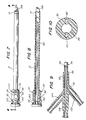
- Figure 1 is a perspective view of a dilatation catheter and sheath assembly in accordance with one embodiment of the present invention;
- Figure 2 is a partial assembly view of the clipping mechanism;
- Figure 3 is a perspective view of a septum, showing an inwardly extending boot sleeve in cut away;
- Figure 3a is a perspective view of a second type of septum, having both boot sleeves projecting outwardly;
- Figure 4 is an end view of the sheath, showing the unique ellipsoid shape of the inner walls thereof;
- Figure 5 is a perspective view of the tip of the sheath, as being deformed by a once-inflated dilatation balloon, so as to guide the balloon into the sheath before removal from the urethral lumen;
- Figure 6 is a side view of the tip of an obturator;
- Figure 7 is a side view of the sheath, having an obturator disposed therein, as ready for insertion into the urethra;
- Figure 8 is a cross-sectional view, taken along line 8-8 of Figure 7, showing in more detail the obturator removably disposed therein;
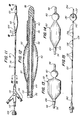
- Figure 9 is a cross-sectional view, illustrating a plastic manifold disposed at the proximal end of the dilatation catheter during the molding process;
- Figure 10 is a cross-sectional view, taken along line 10-10 of Figure 11, showing the lumen arrangement within the catheter shaft;
- Figure 11 is a side view of a dilatation catheter, having a stylet removably inserted therein;
- Figure 12 is a cross-sectional view, taken along line 12-12 of Figure 11, showing the overlap of the shoulder of the locating balloon with the shoulder of the dilatation balloon;
- Figure 13 is a side view of a dilatation balloon, in an inflated state, exhibiting a squared-off configuration at one end, and a tapered configuration at the opposite end thereof, in accordance with one embodiment of the present invention;
- Figure 14 is a side view of a dilatation balloon, having both ends in a tapered configuration, in accordance with an alternative embodiment of the present invention;
- Figure 15 is a side view of a calibration catheter, showing a partial cut away view of an inflation aperture for the expandable balloon;
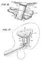
- Figure 16 is a magnified view of the marking disposed near the proximal end of the dilatation balloon showing clearance of the external sphincter muscle; and
- Figure 17 is a cross-sectional view of the urethral dilatation catheter of the present invention operatively inserted within the male urinary tract.
- Referring now to the drawings in detail, wherein like reference numerals designate like elements throughout the several views thereof, there is shown generally at 10 in Fig. 1, a dilatation catheter and sheath assembly embodying the present invention in a preferred form. The
sheath 12 is advantageously a substantially rigid, axially elongate hollow shaft throughout most of its length, but having a flexibledistal tip 14. Thesheath 12 exhibits aninner surface 16 which is substantially ellipsoid in cross-section, and is adapted to receive and guide an axiallyelongate catheter 18 and anendoscope 20 longitudinally therethrough. Advantageously, the particular endoscope used is known as a cystoscope. - In one embodiment of the invention, a
cyclindrical housing 22, disposed near the base of the sheath, exhibits a pair ofgrooves 24, formed upon two flattenedsurfaces 26 of thecylindrical housing 22, on opposite sides thereof. An end view of thecylindrical housing 22, as shown in Figure 4, illustrates the ellipsoid shape of the inner walls 15 of thesheath 12, and the flattened side surfaces 26 thereof. AU-shaped clip 28 is integrally connected to the top of aninflation device 30 and is adapted to removably receive and retain thecylindrical housing 22 so as to enable thedevice 10 to be operated by one person, without the need for assistance. The removable attachment of thesheath 12 to theU-shaped clip 28 is illustrated in Figure 2. A C-shapedclip 32 may also be provided on the body of theinflation device 30, to removably receive and retain thecatheter 18 therein and provide additional support for the proximal end of the device, thus controlling the catheter so it does not interfere with the eyepiece of the endoscope. - Situated on the
underside 36 of thecylindrical housing 22 is adrainage port 38, having acock valve 40 secured therein. Thecock valve 40 is adapted to allow back-flowing fluids to escape thesheath 12 when positioned in the "on" position, and to prohibit the release of such fluids when in the "off" position. - The
cylindrical housing 22 includes ahub portion 42, disposed at the proximal end thereof. Arubberized septum 44, preferably formed from a silicon rubber compound, is detachably placed onto thehub 42 of thecylindrical housing 22 so as to provide a seal therefor. As best seen in Figures 3 and 3a, theseptum 44 is acircular cap 46, having a pair ofboot sleeves cap 46. In one embodiment, theseptum 44 exhibits an outwardly extendingboot sleeve 48 an inwardly extendingboot sleeve 50. Theboot sleeves cystoscope lens 20 and thedilatation catheter 18, and provide theseptum 44 with elasticity at the point of contact therebetween. Without the presence of such sleeves, therubberized septum 44 would itself deform if a force were applied to either thecatheter 18 orcystoscope lens 20, thereby detracting from the septum's sealing ability. Further, theboot sleeves catheter 18 andlens 20 to yield a good seal therebetween. In an alternative embodiment, as shown in Figure 3a, both of theboot sleeves septum cap 44. This embodiment is possible only when there exists sufficient room on the outside of the septum, such that a sharing of a common wall between the two sleeves is not necessitated. - As best seen in Figures 11, the
dilatation catheter 18 of the present invention comprises an axiallyelongate catheter shaft 56, having a tapered guidingend 58, and a plurality of parallel conduits disposed therein. Situated near the guidingend 58 of thecatheter shaft 56 is a locatingballoon 60. The locatingballoon 60 is a small latex Foley-type balloon, adapted for inflation by a source of pressurized fluid. Adjacent the locatingballoon 60 is alarger dilatation balloon 62, having aproximal shoulder 64 and adistal shoulder 66. - A feature of this invention is that the
distal shoulder 66 of thedilatation balloon 62 is overlapped by a portion of the locatingballoon 60, such that, when the balloons are expanded, a minimal valley is left between the two balloons. Both of theballoons catheter shaft 56 by suitable adhesive or thermal process. - While the overlap of the locating
balloon 60 onto theshoulder 66 of thedilatation balloon 62 increases the area of dilatation by minimizing the distance between the locatingballoon 60 and thedilatation balloon 62, suboptimal dilatation of the affectedprostatic urethra 68 still exists due to the tapered nature of expandable balloons, commonly used in dilatation processes. To achieve optimal dilatation near theends prostatic urethra 68, thedilatation balloon 62 can be molded with a steep, squared offend 74, as illustrated in Figure 13. Depending on the nature of the affected area of theprostatic urethra 68, it may be desirable to enable urethral dilatation very close to thebladder neck 72 or theexternal spincter muscle 70. Accordingly, either end of thedilatation balloon 62, neither end, or both ends may be provided with a substantially vertical configuration as illustrated in Figures 13, 14 and 17. - A material which is well adapted to construction of the
dilatation balloon 62 of the present invention is polyethylene terephthalate (PET), such as KODAK's 9921. Preferably, theballoon 62 is extruded in a straight pipe configuration and then stretched and blown under high temperature and pressure to yield the desiredshape 74. This type of technique is commonly applied in the making of angioplasty balloons. It should be noted that the PET material used to construct the dilatation balloon exhibits superior tensile strength characteristics to that of materials used in manufacturing other types of dilatation balloons, for example older angioplasty balloons. The PET material used to construct the dilatation balloon of the present invention has a tensile strength of between 20,000 to 50,000 psi, and is rated to withstand at least 3 atmospheres of pressure, and as much as 5 atm. - If a rubberized latex material were used to fabricate the dilatation balloon of the present invention, the walls of the balloon would necessarily be much thicker in order to withstand the exceedingly high pressures required for adequate dilatation of the affected prostatic urethra. Thus, the PET material, by virtue of its superior strength, allows a thinner balloon to be utilized. The thinness of the balloon thus formed, makes possible a
dilatation balloon 62 which, in an uninflated state, conforms to the external walls of thecatheter shaft 56, thereby providing adilatation catheter 18 having substantially the same size and shape as the unstretched lumen. However, the increased strength of the material also dictates a balloon which is somewhat stiff and substantially less pliable than a latex balloon. - Consequently, when negative pressure is applied to collapse the
dilatation balloon 62 made of the PET material, sharp ridges may form on the exterior surface thereof. Advantageously, thedistal tip 14 of theintroduction sheath 12 is formed of a flexible material, which readily deforms to the gross contours of the deflateddilatation balloon 62, so as to coerce theballoon 62 into theintroduction sheath 12 prior to the withdrawal of thecatheter 18 from the urethra. Preferably, thetip 14 is formed from a substantially malleable Poly Vinyl Chloride (PVC) compound, which is RF welded torigid shaft portion 12 of the sheath. - To ensure that the
catheter 18 is fully within theintroduction sheath 12 prior to the withdrawal thereof, visual indicia, such as the marking 78 on theexterior shaft 56 of thecatheter 18 is provided. As thecatheter shaft 56 and deflateddilatation balloon 62 are gradually withdrawn from the urethra, theindicia 78 will be advanced out of thesheath 12. When the designatedindicia 78 becomes visible, thecatheter 18 is fully retracted within thesheath 12, and thedevice 10 may be withdrawn, without causing undue trauma to the urethral lumen. - As best seen in cross-section in Figure 10, the
catheter shaft 56 houses a pair ofcircular inflation conduits irrigation conduit 84. Theinflation conduit 80 having anaperture 86 underlying the locatingballoon 60 exhibits a tubular passageway which permits pressurized fluid to be transmitted into the chamber enclosed by the locatingballoon 60 , so as to selectively inflate theballoon 60 to a suitable level. Likewise, theinflation conduit 82 having a pair ofinflation apertures dilatation balloon 62 allows pressurized fluid to selectively fill theballoon 62 to a desired level. - To facilitate inflation of the locating
balloon 60, asimple fluid valve 94 may be connected to the proximal end of theconduit 80. Thisvalve 94 is integrally connected to theinflation conduit 80 and may be easily manipulated to allow quick sealing of theconduit 80 and maintain the pressurized fluid within theballoon chamber 60 and theconduit 80. The locatingballoon 60 may be pressurized by inserting a hypodermic syringe (not shown) into thevalve 94, with thevalve 94 in its open condition. By forcing fluid into theconduit 80, the locatingballoon 60, at the distal end of the inflation conduit will be inflated. Thevalve 94 may then be closed, and the hypodermic syringe removed, leaving the locatingballoon 60 in an inflated state. - Since inflation of the
dilatation balloon 62 is more critical, the source ofpressurized fluid 98 used to inflate thedilatation balloon 62 is connected to apressure gauge 100. Preferably, theinflation device 98 includes asyringe barrel 102 having a threaded rod andratchet mechanism 104 which replaces the conventional plunger. This configuration allows fine tuning of the pressure amassed within thedilatation balloon 62 by screw turning the threadedrod 104. It has been determined that an intra-balloon pressure of approximately 3 atm., or 45 p.s.i.g. is sufficient to force the prostate away from the urethral lumen to relieve the obstruction and reestablish normal micturition. - Proximate to the proximal end of the
dilatation balloon 62, and encircling theproximal shoulder 64 thereof, is a heavyblack line 106. Prior to inflating thedilatation balloon 62, care should be taken to ensure that theblack line 106 does not extend onto any portion of the externalurethral sphincter muscle 108. This is vitally important as accidental dilatation of thesphincter 108 may cause the patient to lose voluntary control over micturition, especially if the sphincter experiences plastic deformation, i.e., the inability to return to its original shape. - An important feature of this invention is the provision of an irrigation system. As described below, the system provides the dual features of both flushing blood away from the lens of the cystoscope to aid in the viewing of the external sphincter muscle and the
black line 106 on theshoulder 64 of thedilatation balloon 62 and inhibiting coagulation of blood within the urethra. This flushing system includes a plurality ofirrigation ports 110 disposed along theexterior shaft 56 of thecatheter 18, proximate to theline 106 are provided. Theirrigation ports 110 are adapted to continuously flush fluid, for example, saline, from theirrigation conduit 84, which extends through the center of thecatheter shaft 56. Theirrigation conduit 84 is provided with acoupling device 112 at the proximal end thereof, adapted to receive a source of flushing fluid, which, for example, can be a hanging container of saline (not shown), having a length of flexible tubing extending therefrom, for connection to thecoupling device 112. The source of fluid is elevated and allowed to flow by gravity through theirrigation conduit 84 and out theirrigation ports 110, so as to flush blood away from thelens 20 and allow the urologist an unobstructed view of theexternal sphincter muscle 108 and theline 106 encircling theproximal shoulder 64 of thedilatation balloon 62. - In addition to permitting an unobstructed view of the
proximal shoulder 64 of theballoon 62, the flushing of blood inhibits coagulation, and therefore substantially eliminates clotting within the urethral lumen. Back-flowing flushing fluid and blood is drained from the urethra throughintroduction sheath 12 by gravity flow. A drainage reservoir (not shown) is connected to thecock valve 40 which, when in its open position, allows the back-flowing fluids to drain, by gravity flow, into the reservoir and subsequently disposed of. Alternatively, the flushing fluid can be supplied through thesheath 12 to flush blood away from thecystoscope lens 20. In this embodiment, theirrigation ports 110 of theirrigation conduit 84 function as influent ports to drain the flushing fluid and blood out of the urethra. - Located at the proximal end of the
catheter shaft 56, and integrally connected thereto, is a Y-shaped plastic manifold 119. The manifold 118 is adapted to define and separate the trio ofconduits catheter shaft 56. Preferably, the manifold 118 is preformed in the Y-shaped configuration and is adapted to connect to thecatheter shaft 56 and trio of conduits at the proximal end thereof. Thecatheter shaft 56 should be bent and cut to expose theinflation conduits irrigation conduit 84 need not be exposed in this manner, as the manifold 118 includes a substantially straight portion in which the proximal end of theirrigation conduit 84 will reside. As shown in Figure 9, during the molding process flexible core pins 122, 124 are inserted into the exposedinflation conduits straight core pin 126 is inserted into theirrigation conduit 84, and thecatheter 18 is set into the preformedplastic manifold 118. Plastic is then injected into the manifold 118 to form a tight seal, and the core pins 122, 124, 126 are removed after the plastic has hardened. - Prior to dilating the obstructed urethral lumen, the length of the affected
prostatic urethra 68 should be measured. This may be accomplished by the use of acalibration catheter 128, as illustrated in Figure 15. Thecalibration catheter 128 is an axiallyelongate shaft 130, having anexpandable balloon 132 located near thedistal end 134 thereof, and an inflation conduit (not shown) which extends substantially the entire length of theshaft 130. Theexpandable balloon 132 is adapted to be inflated through aninflation aperture 136, extending from the inflation conduit by a source of pressurized fluid (not shown). A plurality of graduatedmarkings 138 extend along theexterior shaft 130 of thecatheter 128, commencing near theproximal end 140 of theexpandable balloon 132, and are adapted to be read from thedistal end 134 of thecatheter 128 to theproximal end 142. - The
calibration catheter 128 is adapted to be received into the sheath of a standard cystoscope, and the cystoscope inserted into the urethra through the penile meatus. Once thedistal end 134 andexpandable balloon 132 of thecalibration catheter 128 enters thebladder 144, theexpandable balloon 132 may be inflated, and thecatheter 128 slowly withdrawn from the urethra until theballoon 132 becomes lodged within thebladder neck 72.Graduated markings 138, inscribed on theexterior shaft 130 of thecatheter 128 can be used to measure the distance between thebladder neck 72 and thelower end 70 of the affectedprostatic urethra 68. Once such a measurement has been determined, theexpandable balloon 138 may be deflated, and thecatheter 128 withdrawn. - An
introduction sheath 12, as illustrated in Figures 7 and 8 is then readied for insertion through the external urethral opening. Anobturator 146, as shown in Figures 6, 7 and 8, having a smooth,tapered end 148 with no sharp edges is inserted into thesheath 12, and secured to thehub 42 of thecyclindrical housing 22 bychamfered clips 150. Theflexible tip 14 of thesheath 12 tapers inwardly, so as to grip the extending portion of theobturator 146 and provide a fairly smooth surface continuation of the introduction sheath. This mild transition between theobturator 146 andsheath 12 is instrumental in reducing damage and trauma to the tender urethral lumen. Once thesheath 12 has been fully inserted within the urethral lumen, the chamferedclips 150 may be released, and theobturator 146 withdrawn. - A
catheter shaft 56, having adilatation balloon 62 with a length approximately equivalent to that measured by thecalibration catheter 128, is then inserted through one 48 of two boot sleeves of theseptum 44, until at least that portion of thecatheter shaft 56 to which the expansible balloons 60, 62 are attached extends therethrough. Theseptum 44 is then friction fit onto thehub 42 of thecylindrical housing 22 such that thecatheter 18 is in alignment with the largerdiameter ellipsoid section 152 of thesheath 12. Thecystoscope lens 20 is then inserted into theother boot sleeve 50, and is then urged through thesheath 12 and into the urethra after placement of thecatheter 18. - To provide support for the
catheter 18, anelongate stylet 154 may be inserted into theirrigation conduit 84, as illustrated in Figure 11. Thestylet 154 facilitates the ease with which thecatheter 18 may be inserted into the urethra, and may remain within theirrigation conduit 84 until the locatingballoon 60 is disposed within thebladder 144, at which time thestylet 154 should be removed. Once the locatingballoon 60 is within thebladder 144, theinflation conduit 80 may be coupled to a source of pressurized fluid so as to inflate the locatingballoon 60. Thecatheter 18 is then gradually withdrawn from thebladder 144 until theballoon 60 is lodged within thebladder neck 72. When the locatingballoon 60 is properly positioned within theneck 72 of thebladder 144, a seal is formed therebetween which prohibits fluids accumulating within thebladder 144 from travelling down the urethra and also prohibits fluids from flowing into and filling up the bladder from the urethra. - Once the
catheter 18 has been properly situtated with respect to theupper end 72 of the affectedprostatic urethra 68, theirrigation conduit 84 may be connected to a source of flushing fluid. The flushing fluid is gravity fed through theirrigation conduit 84 and out theirrigation ports 110, so as to wash existent blood away from thecystoscope lens 20 and provide the urologist with an unobstructed view of theproximal shoulder 64 of thedilatation balloon 62, and adjacent organs. Looking through the cystoscope, the urologist can manipulate thecatheter 18 to confirm that thedilatation balloon 62 is clear of the externalurethral sphincter muscle 108, so as to ensure that thesphincter 108 will not inadvertently be dilated. - Upon properly positioning the
dilatation balloon 62 with respect to both thebladder neck 72 and thesphincter 108, theinflation conduit 82 for thedilation balloon 62 may be connected to a source ofpressurized fluid 98. As described above, theinflation source 98 should enable a accurate, progressive dilation under constant control of the pressure being applied within thedilatation balloon 62. The device remains within the affectedprostatic urethra 68, until sufficient pressure dilatation has been achieved. Subsequent to attaining adequate pressure dilation of the prostatic urethra, and eliminating the urinary outflow obstruction, theballoons - As the
dilatation balloon 62 is deflated, sharp ridges may form on the outer surface thereof, due to the stiffness of the material from which it was formed. As shown in Figure 5, theflexible tip 14 of theintroduction sheath 12 readily deforms and flares, so as to coerce thedilatation balloon 62 back into thesheath 12. When the marking 78, indicative of the time at which thedilatation balloon 62 is completely within thesheath 12 becomes visible, the device may be withdrawn from the urethra. - In view of the medical treatment to be administered in using the device of the present invention, it is necessary that the device be aseptically clean. Accordingly, the dilatation catheter and sheath can be cleansed and sterilized readily and easily either prior to use thereof, or packaged in this condition, available for immediate use. Further, both the catheter and sheath may be discarded after use, negating the need for recleaning and resterilization.
- It will be appreciated that certain structural variations may suggest themselves to those skilled in the art. The foregoing detailed description is to be clearly understood as given by way of illustration, the spirit and scope of this invention being limited solely by the appended claims.
Claims (11)
an elongate catheter, having a means for dilating the body lumen carried thereon; and
visualizing means associated with the catheter for visualizing the location of the dilating means with respect to the anatomical landmark.
an axially elongate introduction sheath, adapted for insertion into a body lumen;
an axially elongate dilation catheter, having a dilation means secured thereto, said catheter extending through and axially movable within said sheath, to permit positioning of said dilation means within the obstructed body lumen; and
non-radiological locating means extending substantially in parallel with the sheath for ascertaining the position of said dilating means with said body lumen.
an axially elongate introduction sheath, adapted for insertion into the urethra to receive and guide both a catheter shaft and a cystoscopic lens therethrough, so as to minimize trauma to the urethral lining during the insertion of said catheter and said lens;
a tubular, axially elongate, catheter shaft for insertion through said sheath, having a distal end to facilitate manipulation of said device within the urethra;
an expansible locating balloon, disposed near the distal tip of said catheter shaft and bonded thereto; and
a dilation balloon, on said catheter shaft situated proximally of said expansible locating balloon, said dilation balloon outwardly radially expandable to a preselected configuration in response to inflation thereof.
a first inflation lumen in said catheter shaft for transmitting pressurized fluid into and out of said locating balloon, for inflation and deflation thereof;
a second inflation lumen in said catheter shaft for transmitting pressurized fluid into and out of said dilation balloon, for inflation and deflation thereof; and
an irrigation conduit in said apparatus for providing a path through which a supply of flushing fluid may flow so as to flush blood away from the distal end of said cystoscope lens and permit an unobstructed view therethrough.
an axially elongate hollow shaft, providing a path through which said catheter and said endoscope is guided for initial insertion into a body lumen;
a cylindrical housing, mounted to and encircling one end of said shaft;
a rubberized septum, detachably attached to said housing for providing a seal for said shaft;
a pair of boot sleeves, extending outwardly of said housing, said boot sleeves adapted to grip said catheter and said endoscope; and
a flexible tip abutted against the other end of said shaft and bonded thereto, said flexible tip adapted to coerce said catheter back into said sheath prior to removal from said lumen.
an axially elongate hollow sheath;
an endoscopic lens, adapted for insertion into said sheath, providing a means for visualizing various structures within the body; and
an irrigation system for flushing blood away from said lens, said irrigation system including a tubular member for transporting irrigation fluid therethrough, said tubular member adapted for insertion into said sheath, parallel to said endoscope.
an axially elongate catheter shaft;
a dilation balloon, secured proximate to the distal end of said shaft, at shoulder portions, said balloon having a squared configuration with rounded corners at one or both ends; and
an inflation conduit extending longitudinally through said shaft, said conduit adapted to transmit pressurized fluid into and out of said dilation balloon, for selective inflation and deflation thereof. 11. An intraluminal introduction sheath for insertion into a body lumen, adapted to receive and removably retain an endoscope and catheter, said sheath comprising:
an axially elongate hollow shaft, providing a path through which said catheter and said endoscope is guided for initial insertion into a body lumen; and
a flexible tip abutted against one end of said shaft and bonded thereto, said flexible tip coercing said catheter back into said sheath prior to removal from said lumen.
an axially elongate catheter shaft; and
a dilation balloon secured to said shaft at first and second shoulder portions, said balloon having first and second end portions which are preformed such that when said balloon is inflated, at least one of said end portions is steeply inclined from the external surface of said catheter shaft.
Applications Claiming Priority (2)
| Application Number | Priority Date | Filing Date | Title |
|---|---|---|---|
| US07/201,686 US5007898A (en) | 1988-06-02 | 1988-06-02 | Balloon dilatation catheter |
| US201686 | 1988-06-02 |
Publications (2)
| Publication Number | Publication Date |
|---|---|
| EP0345051A2 true EP0345051A2 (en) | 1989-12-06 |
| EP0345051A3 EP0345051A3 (en) | 1990-11-28 |
Family
ID=22746872
Family Applications (1)
| Application Number | Title | Priority Date | Filing Date |
|---|---|---|---|
| EP19890305503 Ceased EP0345051A3 (en) | 1988-06-02 | 1989-06-01 | Balloon dilation catheter |
Country Status (4)
| Country | Link |
|---|---|
| US (1) | US5007898A (en) |
| EP (1) | EP0345051A3 (en) |
| CA (1) | CA1330187C (en) |
| ES (1) | ES2049197T1 (en) |
Cited By (14)
| Publication number | Priority date | Publication date | Assignee | Title |
|---|---|---|---|---|
| EP0442480A1 (en) * | 1990-02-14 | 1991-08-21 | Advanced Cardiovascular Systems, Inc. | Balloon catheter for dilating a prostatic urethra |
| US5090959A (en) * | 1987-04-30 | 1992-02-25 | Advanced Cardiovascular Systems, Inc. | Imaging balloon dilatation catheter |
| WO1992009327A1 (en) * | 1990-11-21 | 1992-06-11 | Johnson Medical Development Corp. | Balloon catheter |
| US5263931A (en) * | 1990-02-14 | 1993-11-23 | Advanced Cardiovascular Systems, Inc. | Balloon catheter for dilating a prostatic urethra |
| US5263962A (en) * | 1990-11-21 | 1993-11-23 | Johnson Medical Development Corp. | Balloon catheter and method of using the same |
| US5330428A (en) * | 1991-05-14 | 1994-07-19 | Scimed Life Systems, Inc. | Dilatation catheter having a random copolymer balloon |
| US5348538A (en) * | 1992-09-29 | 1994-09-20 | Scimed Life Systems, Inc. | Shrinking balloon catheter having nonlinear or hybrid compliance curve |
| EP0707864A1 (en) * | 1994-10-21 | 1996-04-24 | Cordis Europa N.V. | Balloon catheter with several balloons |
| US5632760A (en) * | 1994-10-20 | 1997-05-27 | Cordis Corporation | Balloon catheter for stent implantation |
| WO1998047557A1 (en) * | 1997-04-23 | 1998-10-29 | Pera Giuseppe | Method for the diagnosis, treatment and prophylaxis of premature ejaculation and catheter for the diagnosis, treatment and prophylaxis of premature ejaculation |
| US5846246A (en) * | 1994-10-21 | 1998-12-08 | Cordis Corporation | Dual-balloon rapid-exchange stent delivery catheter with guidewire channel |
| WO2003086524A1 (en) * | 2002-04-11 | 2003-10-23 | University Of South Florida | Dilation ballon for endoscope |
| EP1951101A2 (en) * | 2005-11-08 | 2008-08-06 | The Trustees of Columbia University in the City of New York | Apparatuses and methods for delivering one or more deliverables into a body |
| EP2861287A1 (en) * | 2012-06-13 | 2015-04-22 | Assistance Publique Hôpitaux De Paris | Balloon catheter for measuring the length of a stenosis |
Families Citing this family (108)
| Publication number | Priority date | Publication date | Assignee | Title |
|---|---|---|---|---|
| US5527336A (en) | 1986-12-09 | 1996-06-18 | Boston Scientific Corporation | Flow obstruction treatment method |
| US5312430A (en) * | 1986-12-09 | 1994-05-17 | Rosenbluth Robert F | Balloon dilation catheter |
| US5374261A (en) | 1990-07-24 | 1994-12-20 | Yoon; Inbae | Multifunctional devices for use in endoscopic surgical procedures and methods-therefor |
| US6120437A (en) * | 1988-07-22 | 2000-09-19 | Inbae Yoon | Methods for creating spaces at obstructed sites endoscopically and methods therefor |
| US5514091A (en) * | 1988-07-22 | 1996-05-07 | Yoon; Inbae | Expandable multifunctional manipulating instruments for various medical procedures |
| US5308326A (en) * | 1989-06-28 | 1994-05-03 | Zimmon David S | Balloon tamponade devices and methods for their placement |
| US5250025A (en) * | 1990-08-15 | 1993-10-05 | Intramed Laboratories | Percutaneous access catheter and method of use |
| US5071429A (en) * | 1990-08-24 | 1991-12-10 | Medical Engineering Corporation | Method for inserting a balloon catheter through an endoscope |
| US5163950A (en) * | 1990-08-24 | 1992-11-17 | Medical Engineering Corporation | Balloon catheter and endoscope kit |
| US5188596A (en) * | 1990-09-27 | 1993-02-23 | Mentor Corporation | Transparent prostate dilation balloon and scope |
| US5209725A (en) * | 1991-04-11 | 1993-05-11 | Roth Robert A | Prostatic urethra dilatation catheter system and method |
| US5728119A (en) * | 1991-05-29 | 1998-03-17 | Origin Medsystems, Inc. | Method and inflatable chamber apparatus for separating layers of tissue |
| US6361543B1 (en) | 1991-05-29 | 2002-03-26 | Sherwood Services Ag | Inflatable devices for separating layers of tissue, and methods of using |
| US5632761A (en) * | 1991-05-29 | 1997-05-27 | Origin Medsystems, Inc. | Inflatable devices for separating layers of tissue, and methods of using |
| US5865728A (en) * | 1991-05-29 | 1999-02-02 | Origin Medsystems, Inc. | Method of using an endoscopic inflatable lifting apparatus to create an anatomic working space |
| US5704372A (en) * | 1991-05-29 | 1998-01-06 | Origin Medsystems, Inc. | Endoscopic inflatable retraction devices for separating layers of tissue, and methods of using |
| US5468248A (en) * | 1991-05-29 | 1995-11-21 | Origin Medsystems, Inc. | Endoscopic inflatable retraction devices for separating layers of tissue |
| US5803901A (en) * | 1991-05-29 | 1998-09-08 | Origin Medsystems, Inc. | Inflatable devices for separating layers of tissue and methods of using |
| US5361752A (en) * | 1991-05-29 | 1994-11-08 | Origin Medsystems, Inc. | Retraction apparatus and methods for endoscopic surgery |
| US5370134A (en) * | 1991-05-29 | 1994-12-06 | Orgin Medsystems, Inc. | Method and apparatus for body structure manipulation and dissection |
| CA2109714A1 (en) * | 1991-05-29 | 1992-12-10 | Frederic H. Moll | Retraction apparatus and methods for endoscopic surgery |
| US5562603A (en) * | 1991-05-29 | 1996-10-08 | Origin Medsystems, Inc. | Endoscopic inflatable retraction device with fluid-tight elastomeric window |
| US5527264A (en) * | 1991-05-29 | 1996-06-18 | Origin Medsystem, Inc. | Methods of using endoscopic inflatable retraction devices |
| US5501653A (en) * | 1991-05-29 | 1996-03-26 | Origin Medsystems, Inc. | Abdominal wall lifting retractor with hinged cross-member |
| US5431173A (en) * | 1991-05-29 | 1995-07-11 | Origin Medsystems, Inc. | Method and apparatus for body structure manipulation and dissection |
| US5779728A (en) * | 1991-05-29 | 1998-07-14 | Origin Medsystems, Inc. | Method and inflatable chamber apparatus for separating layers of tissue |
| US7744617B2 (en) * | 1991-05-29 | 2010-06-29 | Covidien Ag | Method and inflatable chamber apparatus for separating layers of tissue |
| US5716327A (en) * | 1991-05-29 | 1998-02-10 | Origin Medsystems, Inc. | Body wall retraction system for wide cavity retraction |
| DE4220701C2 (en) * | 1991-08-02 | 2001-02-08 | Olympus Optical Co | Endoscope cleaning device |
| US5304123A (en) * | 1991-10-24 | 1994-04-19 | Children's Medical Center Corporation | Detachable balloon catheter for endoscopic treatment of vesicoureteral reflux |
| US5431662A (en) * | 1992-02-12 | 1995-07-11 | United States Surgical Corporation | Manipulator apparatus |
| US5571115A (en) * | 1992-02-12 | 1996-11-05 | United States Surgical Corporation | Manipulator apparatus |
| US5273534A (en) * | 1992-02-27 | 1993-12-28 | Knoepfler Dennis J | Laparoscopic T-tube, drain and securing instrument and method therefor |
| US5322501A (en) * | 1992-10-02 | 1994-06-21 | Mahmud Durrani Ayaz | Continent urethral stent for treating and preventing urethral stricture after surgery |
| US5578048A (en) * | 1993-09-15 | 1996-11-26 | United States Surgical Corporation | Manipulator apparatus |
| US5487377A (en) * | 1993-11-05 | 1996-01-30 | Clinical Innovation Associates, Inc. | Uterine manipulator and manipulator tip assembly |
| US5512032A (en) * | 1993-12-23 | 1996-04-30 | Hk Medical Technologies, Inc. | Nonsurgical intraurethral bladder control device |
| US5458612A (en) * | 1994-01-06 | 1995-10-17 | Origin Medsystems, Inc. | Prostatic ablation method and apparatus for perineal approach |
| US5411016A (en) | 1994-02-22 | 1995-05-02 | Scimed Life Systems, Inc. | Intravascular balloon catheter for use in combination with an angioscope |
| US6102929A (en) * | 1994-09-15 | 2000-08-15 | Mentor Urology, Inc. | Prostatic tissue expander |
| US6059734A (en) * | 1995-01-06 | 2000-05-09 | Yoon; Inbae | Methods of collecting tissue at obstructed anatomical sites |
| US6176842B1 (en) * | 1995-03-08 | 2001-01-23 | Ekos Corporation | Ultrasound assembly for use with light activated drugs |
| US6210356B1 (en) * | 1998-08-05 | 2001-04-03 | Ekos Corporation | Ultrasound assembly for use with a catheter |
| US5588965A (en) * | 1995-03-07 | 1996-12-31 | American Medical Systems, Inc. | Device for slowly dilating the prostatic urethra |
| US5980549A (en) * | 1995-07-13 | 1999-11-09 | Origin Medsystems, Inc. | Tissue separation cannula with dissection probe and method |
| US5968065A (en) * | 1995-07-13 | 1999-10-19 | Origin Medsystems, Inc. | Tissue separation cannula |
| US7384423B1 (en) | 1995-07-13 | 2008-06-10 | Origin Medsystems, Inc. | Tissue dissection method |
| US5618257A (en) | 1995-08-16 | 1997-04-08 | Hk Medical Technologies Incorporated | Bladder control insertion apparatus and method |
| US5707355A (en) * | 1995-11-15 | 1998-01-13 | Zimmon Science Corporation | Apparatus and method for the treatment of esophageal varices and mucosal neoplasms |
| US5785641A (en) * | 1996-05-08 | 1998-07-28 | Urocath Corporation | Male indwelling urethral catheter sizing system and insertion method |
| US5830228A (en) * | 1996-05-29 | 1998-11-03 | Urosurge, Inc. | Methods and systems for deployment of a detachable balloon at a target site in vivo |
| US5876426A (en) * | 1996-06-13 | 1999-03-02 | Scimed Life Systems, Inc. | System and method of providing a blood-free interface for intravascular light delivery |
| US6676626B1 (en) | 1998-05-01 | 2004-01-13 | Ekos Corporation | Ultrasound assembly with increased efficacy |
| US6582392B1 (en) * | 1998-05-01 | 2003-06-24 | Ekos Corporation | Ultrasound assembly for use with a catheter |
| US5996585A (en) * | 1997-08-21 | 1999-12-07 | Hk Medical Technologies Incorporated | Nonsurgical intraurethral bladder control device retainer |
| US6074367A (en) * | 1997-10-01 | 2000-06-13 | Scimed Life Systems, Inc. | Preinsertion measurement of catheters |
| US6893430B2 (en) | 1998-02-04 | 2005-05-17 | Wit Ip Corporation | Urethral catheter and guide |
| US6021781A (en) * | 1998-03-18 | 2000-02-08 | Medworks Corporation | Intraurethral pressure monitoring assembly and method of treating incontinence using same |
| US7695470B1 (en) | 1998-08-12 | 2010-04-13 | Maquet Cardiovascular Llc | Integrated vessel ligator and transector |
| EP0979635A2 (en) | 1998-08-12 | 2000-02-16 | Origin Medsystems, Inc. | Tissue dissector apparatus |
| JP2002525168A (en) | 1998-09-30 | 2002-08-13 | インプラ・インコーポレーテッド | Introduction mechanism of implantable stent |
| US6494879B2 (en) | 1998-10-15 | 2002-12-17 | Scimed Life Systems, Inc. | Treating urinary retention |
| US6183413B1 (en) | 1998-12-09 | 2001-02-06 | Hk Medical Technologies Incorporated | Valve for bladder control device |
| US6592602B1 (en) * | 1999-10-08 | 2003-07-15 | General Surgical Innovations, Inc. | Balloon dissection apparatus |
| US6287291B1 (en) | 1999-11-09 | 2001-09-11 | Advanced Cardiovascular Systems, Inc. | Protective sheath for catheters |
| US6685734B1 (en) | 1999-12-17 | 2004-02-03 | Linvatec Biomaterials Oy | Urethral stent delivery system |
| US7044980B2 (en) | 2000-02-03 | 2006-05-16 | Boston Scientific Scimed, Inc. | Facilitating drainage |
| US6964669B1 (en) | 2000-04-12 | 2005-11-15 | Ams Research Corporation | Linear delivery system for deployment of a detachable balloon at a target site in vivo |
| US6716252B2 (en) | 2000-06-30 | 2004-04-06 | Wit Ip Corporation | Prostatic stent with localized tissue engaging anchoring means and methods for inhibiting obstruction of the prostatic urethra |
| US6558313B1 (en) | 2000-11-17 | 2003-05-06 | Embro Corporation | Vein harvesting system and method |
| US7160325B2 (en) | 2001-05-15 | 2007-01-09 | Ams Research Corporation | Implantable medical balloon and valve |
| US6494855B2 (en) * | 2001-05-16 | 2002-12-17 | Scimed Life Systems, Inc. | Draining bodily fluid |
| US20040138702A1 (en) * | 2001-05-31 | 2004-07-15 | Kenneth Peartree | Balloon cannula with over-center clamp |
| US20030004534A1 (en) * | 2001-06-01 | 2003-01-02 | George Stephanie A. | Balloon transporter |
| US6524268B2 (en) | 2001-06-12 | 2003-02-25 | George M. Hayner | Combination ureteral infusion catheter/drainage stent |
| EP1332770A4 (en) * | 2001-09-07 | 2007-08-01 | Tsukada Medical Res Co Ltd | Catheter for treatment of prostatic hypertrophy |
| DE60209799T2 (en) | 2001-12-03 | 2007-01-25 | Ekos Corp., Bothell | CATHETER WITH SEVERAL ULTRASOUND EMITTING PARTS |
| US8506647B2 (en) * | 2002-02-14 | 2013-08-13 | Boston Scientific Scimed, Inc. | System for maintaining body canal patency |
| US7029732B2 (en) * | 2002-02-28 | 2006-04-18 | Boston Scientific Scimed, Inc. | Medical device balloons with improved strength properties and processes for producing same |
| US8226629B1 (en) | 2002-04-01 | 2012-07-24 | Ekos Corporation | Ultrasonic catheter power control |
| US6921371B2 (en) * | 2002-10-14 | 2005-07-26 | Ekos Corporation | Ultrasound radiating members for catheter |
| US7347866B2 (en) * | 2003-03-10 | 2008-03-25 | Boston Scientific Scimed, Inc. | Medical stent and related methods |
| JP2006239219A (en) * | 2005-03-04 | 2006-09-14 | Olympus Medical Systems Corp | Balloon dilator |
| US9770230B2 (en) | 2006-06-01 | 2017-09-26 | Maquet Cardiovascular Llc | Endoscopic vessel harvesting system components |
| WO2008008547A2 (en) * | 2006-07-14 | 2008-01-17 | Ams Research Corporation | Balloon dilation for implantable prosthesis |
| US10182833B2 (en) | 2007-01-08 | 2019-01-22 | Ekos Corporation | Power parameters for ultrasonic catheter |
| US9044568B2 (en) | 2007-06-22 | 2015-06-02 | Ekos Corporation | Method and apparatus for treatment of intracranial hemorrhages |
| US20090187137A1 (en) * | 2007-12-14 | 2009-07-23 | Kim Volz | Ultrasound pulse shaping |
| GB2465334B (en) * | 2008-10-31 | 2013-02-13 | Daniela Andrich | Catheterisation device |
| US20100114063A1 (en) * | 2008-11-04 | 2010-05-06 | Angiodynamics, Inc. | Catheter injection monitoring device |
| US9737195B2 (en) | 2013-03-15 | 2017-08-22 | Sanovas, Inc. | Handheld resector balloon system |
| US20140275763A1 (en) * | 2013-03-15 | 2014-09-18 | Lucent Medical Systems, Inc. | Partially disposable endoscopic device |
| US10349977B2 (en) | 2013-03-15 | 2019-07-16 | Sanovas Intellectual Property, Llc | Resector balloon catheter with multi-port hub |
| US9468365B2 (en) | 2013-03-15 | 2016-10-18 | Sanovas, Inc. | Compact light source |
| US9717578B2 (en) * | 2014-06-12 | 2017-08-01 | Coloplast A/S | Surgical tool adapted for identifying an incision site |
| US9717443B2 (en) | 2014-06-12 | 2017-08-01 | Coloplast A/S | Surgical tool and method for identifying an incision site |
| US10376363B2 (en) * | 2015-04-30 | 2019-08-13 | Edwards Lifesciences Cardiaq Llc | Replacement mitral valve, delivery system for replacement mitral valve and methods of use |
| WO2016201136A1 (en) | 2015-06-10 | 2016-12-15 | Ekos Corporation | Ultrasound catheter |
| US10639455B2 (en) | 2015-10-28 | 2020-05-05 | Becton, Dickinson And Company | Closed IV access device with paddle grip needle hub and flash chamber |
| US10525237B2 (en) | 2015-10-28 | 2020-01-07 | Becton, Dickinson And Company | Ergonomic IV systems and methods |
| JP6937775B2 (en) | 2016-03-18 | 2021-09-22 | プロセプト バイオロボティクス コーポレイション | Minimally invasive methods and systems for hemostasis in bleeding closed tissue volume |
| USD815744S1 (en) | 2016-04-28 | 2018-04-17 | Edwards Lifesciences Cardiaq Llc | Valve frame for a delivery system |
| US10238852B2 (en) * | 2016-10-05 | 2019-03-26 | Becton, Dickinson And Company | Septum housing |
| WO2018097987A1 (en) * | 2016-11-28 | 2018-05-31 | C.R. Bard, Inc. | Ultrasonically flared medical-device components and methods thereof |
| CN108392720A (en) * | 2017-02-07 | 2018-08-14 | 翎秀生物科技(上海)有限公司 | A kind of prostate high pressure dilator |
| EP3668581B1 (en) | 2017-11-28 | 2022-09-21 | St. Jude Medical, Cardiology Division, Inc. | Lumen management catheter |
| US11077288B2 (en) | 2018-11-15 | 2021-08-03 | Biosense Webster (Israel) Ltd. | Flushing balloon catheter for observation and removal of clots under vessel bifurcation conditions |
| CN113713240A (en) * | 2021-08-19 | 2021-11-30 | 重庆医科大学附属儿童医院 | Visual urethra expansion external member |
Citations (7)
| Publication number | Priority date | Publication date | Assignee | Title |
|---|---|---|---|---|
| US3411506A (en) * | 1966-04-11 | 1968-11-19 | Velasco Adolfo Guevara | Method and apparatus for hemostasis |
| FR2351634A1 (en) * | 1976-05-18 | 1977-12-16 | Leroyer Guy | Permanently fitted urinal probe - has inlets in walls for inflating bladder ring and seal for closing urethral tract against infection |
| GB1547328A (en) * | 1978-01-19 | 1979-06-13 | Celestin L R | Apparatus for insertion into a body cavity |
| US4445892A (en) * | 1982-05-06 | 1984-05-01 | Laserscope, Inc. | Dual balloon catheter device |
| DE8511340U1 (en) * | 1985-04-17 | 1985-05-30 | Willy Rüsch AG, 7053 Kernen | Vascular endoscopy instrument |
| US4660560A (en) * | 1985-05-30 | 1987-04-28 | The Beth Israel Hospital Association | Method for treating obstructive prostatism |
| US4738659A (en) * | 1986-05-19 | 1988-04-19 | Sleiman Raymond A | Catheter and its method of use with a cystoscopic lens |
Family Cites Families (18)
| Publication number | Priority date | Publication date | Assignee | Title |
|---|---|---|---|---|
| FR351634A (en) * | 1905-02-21 | 1905-07-21 | Harry Gale Nye | Bushing for threading conical screws |
| US2799273A (en) * | 1955-03-22 | 1957-07-16 | Vincent J Oddo | Haemostatic catheter |
| US2936760A (en) * | 1956-09-10 | 1960-05-17 | Davol Rubber Co | Positive pressure catheter |
| US3045677A (en) * | 1960-05-03 | 1962-07-24 | American Cystoscope Makers Inc | Inflatable balloon catheter |
| US3720199A (en) * | 1971-05-14 | 1973-03-13 | Avco Corp | Safety connector for balloon pump |
| US3848602A (en) * | 1972-04-19 | 1974-11-19 | Gutnick Morton | Abortion facilitating device and process |
| US3835842A (en) * | 1972-07-03 | 1974-09-17 | J Iglesias | Endoscope with continuous irrigation |
| US3977408A (en) * | 1974-11-01 | 1976-08-31 | Mackew Allan H | Prosthetic catheter |
| US4396021A (en) * | 1980-12-15 | 1983-08-02 | Baumgartner George C | Surgical instrument and process |
| DE3141022A1 (en) * | 1981-10-15 | 1983-04-28 | Siemens AG, 1000 Berlin und 8000 München | ULTRASONIC PROBE INSERTABLE INTO A BODY |
| US4636346A (en) * | 1984-03-08 | 1987-01-13 | Cordis Corporation | Preparing guiding catheter |
| US4838881A (en) * | 1984-05-04 | 1989-06-13 | Deseret Medical, Inc. | Multilumen catheter and associated IV tubing |
| US4587975A (en) * | 1984-07-02 | 1986-05-13 | Cardiac Pacemakers, Inc. | Dimension sensitive angioplasty catheter |
| EP0203124B1 (en) * | 1984-11-15 | 1991-06-05 | NAZARI, Stefano | Device for selective bronchial intubation and separate lung ventilation |
| US4664114A (en) * | 1985-08-12 | 1987-05-12 | Kamran Ghodsian | Dilator for cervical canal |
| US4733652A (en) * | 1985-12-31 | 1988-03-29 | Aisin Seiki Kabushiki Kaisha | Intra-aortic balloon |
| US4763654A (en) * | 1986-09-10 | 1988-08-16 | Jang G David | Tandem independently inflatable/deflatable multiple diameter balloon angioplasty catheter systems and method of use |
| US4744366A (en) * | 1986-09-10 | 1988-05-17 | Jang G David | Concentric independently inflatable/deflatable multiple diameter balloon angioplasty catheter systems and method of use |
-
1988
- 1988-06-02 US US07/201,686 patent/US5007898A/en not_active Expired - Lifetime
-
1989
- 1989-06-01 ES ES89305503T patent/ES2049197T1/en active Pending
- 1989-06-01 EP EP19890305503 patent/EP0345051A3/en not_active Ceased
- 1989-06-01 CA CA000601442A patent/CA1330187C/en not_active Expired - Fee Related
Patent Citations (7)
| Publication number | Priority date | Publication date | Assignee | Title |
|---|---|---|---|---|
| US3411506A (en) * | 1966-04-11 | 1968-11-19 | Velasco Adolfo Guevara | Method and apparatus for hemostasis |
| FR2351634A1 (en) * | 1976-05-18 | 1977-12-16 | Leroyer Guy | Permanently fitted urinal probe - has inlets in walls for inflating bladder ring and seal for closing urethral tract against infection |
| GB1547328A (en) * | 1978-01-19 | 1979-06-13 | Celestin L R | Apparatus for insertion into a body cavity |
| US4445892A (en) * | 1982-05-06 | 1984-05-01 | Laserscope, Inc. | Dual balloon catheter device |
| DE8511340U1 (en) * | 1985-04-17 | 1985-05-30 | Willy Rüsch AG, 7053 Kernen | Vascular endoscopy instrument |
| US4660560A (en) * | 1985-05-30 | 1987-04-28 | The Beth Israel Hospital Association | Method for treating obstructive prostatism |
| US4738659A (en) * | 1986-05-19 | 1988-04-19 | Sleiman Raymond A | Catheter and its method of use with a cystoscopic lens |
Cited By (21)
| Publication number | Priority date | Publication date | Assignee | Title |
|---|---|---|---|---|
| US5090959A (en) * | 1987-04-30 | 1992-02-25 | Advanced Cardiovascular Systems, Inc. | Imaging balloon dilatation catheter |
| US5263931A (en) * | 1990-02-14 | 1993-11-23 | Advanced Cardiovascular Systems, Inc. | Balloon catheter for dilating a prostatic urethra |
| EP0442480A1 (en) * | 1990-02-14 | 1991-08-21 | Advanced Cardiovascular Systems, Inc. | Balloon catheter for dilating a prostatic urethra |
| WO1992009327A1 (en) * | 1990-11-21 | 1992-06-11 | Johnson Medical Development Corp. | Balloon catheter |
| US5263962A (en) * | 1990-11-21 | 1993-11-23 | Johnson Medical Development Corp. | Balloon catheter and method of using the same |
| US5330428A (en) * | 1991-05-14 | 1994-07-19 | Scimed Life Systems, Inc. | Dilatation catheter having a random copolymer balloon |
| US5348538A (en) * | 1992-09-29 | 1994-09-20 | Scimed Life Systems, Inc. | Shrinking balloon catheter having nonlinear or hybrid compliance curve |
| US5403340A (en) * | 1992-09-29 | 1995-04-04 | Scimed Lifesystems Inc. | Shrinking balloon catheter having nonlinear compliance curve |
| US5500181A (en) * | 1992-09-29 | 1996-03-19 | Scimed Life Systems, Inc. | Shrinking balloon catheter having nonlinear compliance curve |
| US5632760A (en) * | 1994-10-20 | 1997-05-27 | Cordis Corporation | Balloon catheter for stent implantation |
| US5733299A (en) * | 1994-10-20 | 1998-03-31 | Cordis Corporation | Two balloon catheter |
| NL9401759A (en) * | 1994-10-21 | 1996-06-03 | Cordis Europ | Balloon catheter with several balloons. |
| EP0707864A1 (en) * | 1994-10-21 | 1996-04-24 | Cordis Europa N.V. | Balloon catheter with several balloons |
| US5846246A (en) * | 1994-10-21 | 1998-12-08 | Cordis Corporation | Dual-balloon rapid-exchange stent delivery catheter with guidewire channel |
| WO1998047557A1 (en) * | 1997-04-23 | 1998-10-29 | Pera Giuseppe | Method for the diagnosis, treatment and prophylaxis of premature ejaculation and catheter for the diagnosis, treatment and prophylaxis of premature ejaculation |
| WO2003086524A1 (en) * | 2002-04-11 | 2003-10-23 | University Of South Florida | Dilation ballon for endoscope |
| US6953431B2 (en) | 2002-04-11 | 2005-10-11 | University Of South Florida | Eccentric dilation balloons for use with endoscopes |
| US8298134B2 (en) | 2002-04-11 | 2012-10-30 | University Of South Florida | Eccentric dilation balloons for use with endoscopes |
| EP1951101A2 (en) * | 2005-11-08 | 2008-08-06 | The Trustees of Columbia University in the City of New York | Apparatuses and methods for delivering one or more deliverables into a body |
| EP1951101A4 (en) * | 2005-11-08 | 2011-09-28 | Univ Columbia | Apparatuses and methods for delivering one or more deliverables into a body |
| EP2861287A1 (en) * | 2012-06-13 | 2015-04-22 | Assistance Publique Hôpitaux De Paris | Balloon catheter for measuring the length of a stenosis |
Also Published As
| Publication number | Publication date |
|---|---|
| CA1330187C (en) | 1994-06-14 |
| EP0345051A3 (en) | 1990-11-28 |
| US5007898A (en) | 1991-04-16 |
| ES2049197T1 (en) | 1994-04-16 |
Similar Documents
| Publication | Publication Date | Title |
|---|---|---|
| US5007898A (en) | Balloon dilatation catheter | |
| EP0417189B1 (en) | Balloon dilation catheter | |
| US5836951A (en) | Balloon dilation catheter | |
| US5312430A (en) | Balloon dilation catheter | |
| US5314443A (en) | Prostate balloon dilatation catheter | |
| US4932958A (en) | Prostate balloon dilator | |
| US20230139854A1 (en) | Safe urinary catheter and manufacturing method | |
| US5209725A (en) | Prostatic urethra dilatation catheter system and method | |
| US5188595A (en) | Method for enhanced retention of balloon catheter in body cavity | |
| US4932956A (en) | Prostate balloon dilator | |
| US5263931A (en) | Balloon catheter for dilating a prostatic urethra | |
| US8475435B2 (en) | Partial-length indwelling urinary catheter permitting selective urine discharge | |
| US6893430B2 (en) | Urethral catheter and guide | |
| EP0935977A2 (en) | Urethral catheter and guide | |
| JPS59502134A (en) | Opening device to body cavity | |
| WO1986007267A1 (en) | Variable diameter catheter | |
| US20080033570A1 (en) | Prostatic stent placement device | |
| EP0421031B1 (en) | Prostate balloon dilator | |
| EP0442480A1 (en) | Balloon catheter for dilating a prostatic urethra | |
| IL92229A (en) | Prostate balloon dilator | |
| Carruthers et al. | Catheters | |
| IE893599A1 (en) | Prostate balloon dilator |
Legal Events
| Date | Code | Title | Description |
|---|---|---|---|
| PUAI | Public reference made under article 153(3) epc to a published international application that has entered the european phase |
Free format text: ORIGINAL CODE: 0009012 |
|
| AK | Designated contracting states |
Kind code of ref document: A2 Designated state(s): ES |
|
| PUAL | Search report despatched |
Free format text: ORIGINAL CODE: 0009013 |
|
| AK | Designated contracting states |
Kind code of ref document: A3 Designated state(s): ES |
|
| 17P | Request for examination filed |
Effective date: 19910626 |
|
| 17Q | First examination report despatched |
Effective date: 19930622 |
|
| RAP1 | Party data changed (applicant data changed or rights of an application transferred) |
Owner name: BOSTON SCIENTIFIC CORPORATION |
|
| REG | Reference to a national code |
Ref country code: ES Ref legal event code: BA2A Ref document number: 2049197 Country of ref document: ES Kind code of ref document: T1 |
|
| STAA | Information on the status of an ep patent application or granted ep patent |
Free format text: STATUS: THE APPLICATION HAS BEEN REFUSED |
|
| 18R | Application refused |
Effective date: 19940829 |