EP0345133A1 - Device to fasten a part to a support, in particular an implant to a bone - Google Patents
Device to fasten a part to a support, in particular an implant to a bone Download PDFInfo
- Publication number
- EP0345133A1 EP0345133A1 EP89401450A EP89401450A EP0345133A1 EP 0345133 A1 EP0345133 A1 EP 0345133A1 EP 89401450 A EP89401450 A EP 89401450A EP 89401450 A EP89401450 A EP 89401450A EP 0345133 A1 EP0345133 A1 EP 0345133A1
- Authority
- EP
- European Patent Office
- Prior art keywords
- head
- fixing member
- support
- screw
- counterbore
- Prior art date
- Legal status (The legal status is an assumption and is not a legal conclusion. Google has not performed a legal analysis and makes no representation as to the accuracy of the status listed.)
- Granted
Links
- 210000000988 bone and bone Anatomy 0.000 title claims abstract description 16
- 239000007943 implant Substances 0.000 title claims abstract description 9
- 239000000463 material Substances 0.000 claims abstract description 23
- 230000000295 complement effect Effects 0.000 claims abstract description 6
- 230000000903 blocking effect Effects 0.000 claims description 8
- 230000006835 compression Effects 0.000 claims description 4
- 238000007906 compression Methods 0.000 claims description 4
- 239000000126 substance Substances 0.000 abstract 1
- 239000012634 fragment Substances 0.000 description 8
- 210000000588 acetabulum Anatomy 0.000 description 4
- 230000015556 catabolic process Effects 0.000 description 3
- 238000006731 degradation reaction Methods 0.000 description 3
- 238000006073 displacement reaction Methods 0.000 description 2
- 230000000694 effects Effects 0.000 description 2
- 210000001621 ilium bone Anatomy 0.000 description 2
- 238000007789 sealing Methods 0.000 description 2
- 238000004873 anchoring Methods 0.000 description 1
- 239000004568 cement Substances 0.000 description 1
- 238000010276 construction Methods 0.000 description 1
- 230000001054 cortical effect Effects 0.000 description 1
- 230000001627 detrimental effect Effects 0.000 description 1
- 210000003275 diaphysis Anatomy 0.000 description 1
- 210000002745 epiphysis Anatomy 0.000 description 1
- 210000001624 hip Anatomy 0.000 description 1
- 238000009434 installation Methods 0.000 description 1
- 238000004519 manufacturing process Methods 0.000 description 1
- 230000000873 masking effect Effects 0.000 description 1
- 239000011505 plaster Substances 0.000 description 1
- 230000000750 progressive effect Effects 0.000 description 1
- 230000000717 retained effect Effects 0.000 description 1
- 239000003566 sealing material Substances 0.000 description 1
- 238000010008 shearing Methods 0.000 description 1
- 238000001356 surgical procedure Methods 0.000 description 1
- 210000000689 upper leg Anatomy 0.000 description 1
Images


Classifications
-
- A—HUMAN NECESSITIES
- A61—MEDICAL OR VETERINARY SCIENCE; HYGIENE
- A61B—DIAGNOSIS; SURGERY; IDENTIFICATION
- A61B17/00—Surgical instruments, devices or methods, e.g. tourniquets
- A61B17/56—Surgical instruments or methods for treatment of bones or joints; Devices specially adapted therefor
- A61B17/58—Surgical instruments or methods for treatment of bones or joints; Devices specially adapted therefor for osteosynthesis, e.g. bone plates, screws, setting implements or the like
- A61B17/68—Internal fixation devices, including fasteners and spinal fixators, even if a part thereof projects from the skin
- A61B17/80—Cortical plates, i.e. bone plates; Instruments for holding or positioning cortical plates, or for compressing bones attached to cortical plates
- A61B17/8033—Cortical plates, i.e. bone plates; Instruments for holding or positioning cortical plates, or for compressing bones attached to cortical plates having indirect contact with screw heads, or having contact with screw heads maintained with the aid of additional components, e.g. nuts, wedges or head covers
- A61B17/8042—Cortical plates, i.e. bone plates; Instruments for holding or positioning cortical plates, or for compressing bones attached to cortical plates having indirect contact with screw heads, or having contact with screw heads maintained with the aid of additional components, e.g. nuts, wedges or head covers the additional component being a cover over the screw head
-
- A—HUMAN NECESSITIES
- A61—MEDICAL OR VETERINARY SCIENCE; HYGIENE
- A61F—FILTERS IMPLANTABLE INTO BLOOD VESSELS; PROSTHESES; DEVICES PROVIDING PATENCY TO, OR PREVENTING COLLAPSING OF, TUBULAR STRUCTURES OF THE BODY, e.g. STENTS; ORTHOPAEDIC, NURSING OR CONTRACEPTIVE DEVICES; FOMENTATION; TREATMENT OR PROTECTION OF EYES OR EARS; BANDAGES, DRESSINGS OR ABSORBENT PADS; FIRST-AID KITS
- A61F2/00—Filters implantable into blood vessels; Prostheses, i.e. artificial substitutes or replacements for parts of the body; Appliances for connecting them with the body; Devices providing patency to, or preventing collapsing of, tubular structures of the body, e.g. stents
- A61F2/02—Prostheses implantable into the body
- A61F2/30—Joints
- A61F2/32—Joints for the hip
- A61F2/34—Acetabular cups
-
- F—MECHANICAL ENGINEERING; LIGHTING; HEATING; WEAPONS; BLASTING
- F16—ENGINEERING ELEMENTS AND UNITS; GENERAL MEASURES FOR PRODUCING AND MAINTAINING EFFECTIVE FUNCTIONING OF MACHINES OR INSTALLATIONS; THERMAL INSULATION IN GENERAL
- F16B—DEVICES FOR FASTENING OR SECURING CONSTRUCTIONAL ELEMENTS OR MACHINE PARTS TOGETHER, e.g. NAILS, BOLTS, CIRCLIPS, CLAMPS, CLIPS OR WEDGES; JOINTS OR JOINTING
- F16B39/00—Locking of screws, bolts or nuts
- F16B39/02—Locking of screws, bolts or nuts in which the locking takes place after screwing down
- F16B39/10—Locking of screws, bolts or nuts in which the locking takes place after screwing down by a plate, spring, wire or ring immovable with regard to the bolt or object and mainly perpendicular to the axis of the bolt
-
- A—HUMAN NECESSITIES
- A61—MEDICAL OR VETERINARY SCIENCE; HYGIENE
- A61F—FILTERS IMPLANTABLE INTO BLOOD VESSELS; PROSTHESES; DEVICES PROVIDING PATENCY TO, OR PREVENTING COLLAPSING OF, TUBULAR STRUCTURES OF THE BODY, e.g. STENTS; ORTHOPAEDIC, NURSING OR CONTRACEPTIVE DEVICES; FOMENTATION; TREATMENT OR PROTECTION OF EYES OR EARS; BANDAGES, DRESSINGS OR ABSORBENT PADS; FIRST-AID KITS
- A61F2/00—Filters implantable into blood vessels; Prostheses, i.e. artificial substitutes or replacements for parts of the body; Appliances for connecting them with the body; Devices providing patency to, or preventing collapsing of, tubular structures of the body, e.g. stents
- A61F2/02—Prostheses implantable into the body
- A61F2/30—Joints
- A61F2/32—Joints for the hip
- A61F2/34—Acetabular cups
- A61F2002/3401—Acetabular cups with radial apertures, e.g. radial bores for receiving fixation screws
Definitions
- the present invention relates to a device for securing a part to a support using at least one fixing member anchored in the support.
- the screwing of the screw in the support results in a compression force on contact between the part and the support, which is supposed to generate friction forces at the part-support interface which must avoid any relative movement of the part with respect to to support.
- the problem is even more important, especially in the case of surgery where implants must be fixed on bones.
- impaction phenomena can occur between bone fragments or between these fragments and the implant, which leads to a displacement of the implant relative to the screw, if we consider that it the screw does not move relative to the bone into which it is screwed.
- the assembly is then unstable and the initial geometry is not preserved.
- An improvement of an assembly of a part on a support using screws consists in orienting the longitudinal axes of the screws obliquely to each other.
- the degradation of the interface gives a certain freedom to the part which, when subjected to forces, tends to exert torques on the screws, since the head of the screw is free in translation and in rotation relative to the room.
- the axis of the screw previously diverging from the direction of the tearing force is gradually found parallel to it, facilitating tearing.
- the object of the present invention is to propose a device for securing a part and a support, using at least one fixing member, which remains stable when the material of the support is liable to degrade on 'part-support interface and which offers better resistance to tearing.
- This device must also be simple, inexpensive, easy to set up and dismantle.
- a device for securing a part to a support using at least one fixing member comprising a head and a rod anchored in the material of the support, the part delimiting a passage through which the rod of the fixing and a counterbore whose diameter is greater than that of the head of the fixing member so as to define a bottom constituting a bearing surface for said head, an additional blocking member being received and fixed in this counterbore, characterized in that the additional blocking member is externally threaded and cooperates with an internal thread formed in the side wall of the counterbore, this blocking member exerting on the head of the fixing member an axial compressive force which applies it against the bottom of the counterbore.
- the invention also relates to an assembly produced by means of at least one such device as well as its use in the surgical field.
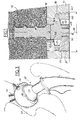
- Fig.1 a device according to the invention ensuring the attachment of a part 10 on a support 12 using a screw 14.
- This screw comprises a threaded rod 16 which penetrates into the material constituting the support and a head 18 which cooperates with the part 10.
- the head 18 comprises a non-threaded cylindrical intermediate part 20 of diameter " d ", a flange 22 of a diameter " D " greater than the diameter d whose face 24 oriented towards the rod is convex and whose opposite face 26 is preferably frustoconical, as well as a cylindrical pin 30.
- bores 32 distributed regularly. In the example shown, there are three bores arranged at 120 °.
- the part 10 comprises a passage 34 and a counterbore 36 opening respectively on the faces 38 directed towards the support, and 40 directed towards the outside.
- the passage 34 has a diameter slightly greater than the diameter d .
- the counterbore 36 it is coaxial with this passage. It further comprises a thread 37 which preferably has a pitch opposite to that of the screw.
- the bottom 42 of the counterbore is concave to cooperate by complementarity of shape with the face 24 of the flange.
- a threaded blocking member 46 which will also be designated by the term screw cooperates with the tapped part of the countersink 36.
- This screw 46 comprises a bore 48 centered so as to be coaxial with the screw and adapted to receive the pin 30 with a weak game.
- the end face 50 of the screw 46 has a profile complementary to that of the face 26 of the collar 22.
- the locking screw 46 is also provided with bores 52 similar to the bores 32 of the flange and distributed in the same way.
- the pin 30 when the flange 22 comes into contact with the bottom 42 of the counterbore 36, the pin 30 must be flush with the accessible face 40 without protruding.
- the length of the locking screw 46 must be such that when its end 50 bears on the face 26 of the flange, this screw is flush with the accessible face 40 without projecting.
- the locking screw 46 is screwed into the counterbore 36, preferably using the same tool as previously until firmly applying the flange 22 against the bottom 24 of the counterbore, therefore ensuring the fastening of the screw 14 relative to the Exhibit 10.
- the axial forces exerted on the part are transmitted to the support material via the threads of the screw 14, without intervention of the interface between the part and the support.
- the joining of the part 10 and the support 12 does not depend on a compressive force which applies them against each other, nor consequently on the friction forces at their interface, but results from a sealing effect achieved by the anchoring of the fixing member (screw 14 or other) in the support, then fixing the part 10 on this member by means of the screw 46.
- the transverse forces are taken up by the intermediate part 20 and the pin 30 which, respectively bearing on the walls of the passage 34 and on the walls of the bore 48 of the locking screw 46, oppose the rotation of the screw relative to the plate, generated by such components.
- the fixing screw is screwed into the support without the part coming directly into contact with the latter. This may correspond to the case where a layer of a material of low hardness (not shown) is interposed between the support 12 and the part 10.
- the screw 14 can be replaced by a nail or other non-threaded fixing member and simply comprising a rod anchored in the material of the support 12.
- Fig.2 shows an application of the invention in the medical field, where the support 12 of Fig.1 is constituted by a femur 54 having suffered a double fracture of the epiphysis and diaphysis. The part 10 is then a plate 60 which maintains in position the two fragments 56 and 58.
- This plate comprises several fixing screws of the type described above, the rod of which passes through the plate and the head of which is fixed in the plate by corresponding locking screws.
- the material of the su port includes the bone formed by the cortical bone material proper and the cancellous bone of low mechanical resistance placed in the central part of the bone.
- the housing of the fixing screws that is to say the passages and the counterbores, are oriented so that the axes of the screws are oriented obliquely with respect to each other, which increases the resistance to tearing.
- the fragment 58 is maintained in position relative to the plate, even in the case of degradation of the bone material at the interface with the plate. Indeed, the screws are immobilized relative to the fragment 58 and, as the screws are themselves immobilized relative to the plate, the fragment 58 retains its initial position both in translation and in rotation around one of the screw heads .
- Fig.3 shows another application of the invention in the medical field, namely the fixation of an acetabular piece 62 on the iliac bone 64 in the case of a hip prosthesis.
- the shell 66 of the acetabular piece 62 is substantially hemispherical and comprises housings distributed over its surface intended to receive fixing screws 14 and locking 46 as described above.
- the internal shape of the shell of the acetabulum is adapted to receive a jacket 68, masking the housings and the heads of screw, which is intended to cooperate with a ball joint 70 of a complementary part of the acetabulum.
- This jacket 68 must be immobilized in rotation relative to the shell and, for this purpose, they both have, respectively externally and internally, the shape of a trunk of a pyramid.
- the anchors formed by the screws can thus be transferred to a relatively large distance from the part.
- the device according to the invention is not limited only to acetabular plates and parts but applies to the fixing of all types of implants or ancillary equipment, that is to say of a material fixed temporarily and which makes it possible to position a prosthesis.
- the invention is suitable for the case of a non-metallic part 10, the material of which lends itself poorly to the production of a tapped recess of relatively small diameter.
- a metallic insert 100 comprising an external thread 102 and a recess 103 provided with an internal thread 104. This insert delimits a bearing surface 105 for the head 106a of a fixing member 106 and a passage 108 for the rod 106b of this fixing member.
- the device is completed by a blocking member 110 externally threaded as well as by a cap 112 provided with lugs 114 which come to engage in grooves 116 formed at the periphery of the part 100.
- the invention finds a particularly advantageous application in the surgical field, it can also have great advantages in other sectors, such as construction or DIY, and replace there the plug tabs or sealing tabs which require the use of plaster, cement or other sealing material and do not offer the same possibilities, in particular disassembly.
Abstract
Description
La présente invention concerne un dispositif de solidarisation d'une pièce sur un support à l'aide d'au moins un organe de fixation ancré dans le support.The present invention relates to a device for securing a part to a support using at least one fixing member anchored in the support.
Il est connu de fixer une pièce sur un support à l'aide de vis comprenant une tête et une tige filetée, cette dernière passant à travers la pièce pour se visser dans la matière constituant le support, tandis que la tête vient au contact de la pièce.It is known to fix a part on a support using screws comprising a head and a threaded rod, the latter passing through the part to be screwed into the material constituting the support, while the head comes into contact with the room.
Le vissage de la vis dans le support se traduit par un effort de compression au contact entre la pièce et le support, qui est supposé générer des forces de frottement à l'interface pièce-support qui doivent éviter tout mouvement relatif de la pièce par rapport au support.The screwing of the screw in the support results in a compression force on contact between the part and the support, which is supposed to generate friction forces at the part-support interface which must avoid any relative movement of the part with respect to to support.
Un premier problème se pose dans le cas où la matière du support s'altère à l'interface avec la pièce car les forces de frottement diminuent jusqu'à devenir nulles, ce qui rend la pièce sensible aux efforts suivant des directions perpendiculaires à son axe longitudinal, et peut provoquer l'apparition d'un jeu de la vis dans le support, puis à la longue son arrachement, et à tout le moins laisse une certaine liberté à la pièce, intolérable dans certaines applications.A first problem arises in the case where the material of the support is altered at the interface with the part because the friction forces decrease until it becomes zero, which makes the part sensitive to the forces in directions perpendicular to its axis. longitudinal, and can cause the appearance of a play of the screw in the support, then in the long run its tearing, and at the very least leaves a certain freedom to the part, intolerable in certain applications.
C'est le cas d'un mur en béton, revêtu d'une couche de finition de faible dureté, sur lequel on doit fixer une pièce à l'aide d'au moins une vis. La couche de finition peut s'altérer et bien que la vis soit fixée dans le béton et parfaitement ancrée, la pièce acquiert une certaine liberté de déplacement par rapport au mur, préjudiciable à la bonne tenue de l'assemblage. Sous l'effet de cycles répétés de chargement-déchargement qui conduisent à des déplacements relatifs de la pièce par rapport à la vis, celle-ci peut acquérir une certaine mobilité par dégradation progressive autour de ses filets de la matière du support, dans ce cas le béton.This is the case of a concrete wall, coated with a finish layer of low hardness, on which a part must be fixed using at least one screw. The finishing layer can deteriorate and although the screw is fixed in the concrete and perfectly anchored, the part acquires a certain freedom of movement relative to the wall, detrimental to the good behavior of the assembly. Under the effect of repeated loading-unloading cycles which lead to displacements relative to the part with respect to the screw, the latter can acquire a certain mobility by progressive degradation around its threads of the support material, in this case concrete.
Pour certaines utilisations, le problème s'avère plus important encore, notamment dans le cas de la chirurgie où des implants doivent être fixés sur des os. En cas de fracture par exemple, il est necessaire pour obtenir un montage stable de supprimer tout mouvement relatif des fragments ainsi que celui de ces fragments par rapport à l'implant.For certain uses, the problem is even more important, especially in the case of surgery where implants must be fixed on bones. In the event of a fracture, for example, it is necessary to obtain a stable assembly to suppress any relative movement of the fragments as well as that of these fragments relative to the implant.
Par ailleurs, des phénomènes d'impaction peuvent se produire entre les fragments d'os ou entre ces fragments et l'implant, ce qui conduit à un déplacement de l'implant par rapport à la vis, si l'on considère qu'il n y a pas déplacement de la vis par rapport à l'os dans lequel elle est vissée. Le montage est alors instable et la géométrie initiale n'est pas conservée.Furthermore, impaction phenomena can occur between bone fragments or between these fragments and the implant, which leads to a displacement of the implant relative to the screw, if we consider that it the screw does not move relative to the bone into which it is screwed. The assembly is then unstable and the initial geometry is not preserved.
Un perfectionnement d'un assemblage d'une pièce sur un support à l'aide de vis consiste à orienter les axes longitudinaux des vis de façon oblique l'un par rapport à l'autre.An improvement of an assembly of a part on a support using screws consists in orienting the longitudinal axes of the screws obliquely to each other.
Dans ce cas, la dégradation de l'interface confère une certaine liberté à la pièce qui, lorsqu'elle est soumise à des efforts, tend à exercer des couples sur les vis, puisque la tête de la vis est libre en translation et en rotation par rapport à la pièce. L'axe de la vis préalablement divergent par rapport à la direction de l'effort d'arrachement se retrouve progressivement parallèle à celui-ci, facilitant l'arrachement.In this case, the degradation of the interface gives a certain freedom to the part which, when subjected to forces, tends to exert torques on the screws, since the head of the screw is free in translation and in rotation relative to the room. The axis of the screw previously diverging from the direction of the tearing force is gradually found parallel to it, facilitating tearing.
On connaît par ailleurs (US-A-4 683 108), un dispositif utilisé dans un réacteur nucléaire et per mettant de bloquer et de remplacer des vis. Ce dispositif comprend une coupelle de blocage à expansion, qui est reçue dans un logement de la pièce dans lequel est également disposée la tête de la vis, et qui est solidaire en rotation de cette tête. De la sorte, la tête de vis est empêchée de tourner par la coupelle et elle est également retenue en cas de rupture accidentelle de la tige. Un tel dispositif offre cependant des inconvénients tels qu'il ne résout pas le problème évoqué ci-dessus. En effet:
- il n'assure pas une résistance axiale importante aux efforts axiaux tendant à éloigner la tête de la vis de sa surface d'appui adjacente car cette résistance est limitée à l'effort nécessaire pour déformer la paroi latérale de la coupelle;
- de la même manière, il ne réalise pas une solidarisation efficace de la tête de vis et de la pièce contre laquelle elle est en appui car la coupelle n'exerce pas d'effort axial sur la tête de la vis;
- il nécessite un outillage tout-à-fait spécifique pour réaliser l'expansion de la paroi latérale de la coupelle de blocage;
- il n'est pas démontable puisque la déformation de la coupelle est permanente.We also know (US-A-4 683 108), a device used in a nuclear reactor and for putting to lock and replace screws. This device comprises an expansion blocking cup, which is received in a housing of the part in which the head of the screw is also disposed, and which is integral in rotation with this head. In this way, the screw head is prevented from rotating by the cup and it is also retained in the event of accidental breakage of the rod. However, such a device has drawbacks such that it does not solve the problem mentioned above. Indeed:
- It does not provide significant axial resistance to axial forces tending to move the head of the screw away from its adjacent bearing surface because this resistance is limited to the force necessary to deform the side wall of the cup;
- in the same way, it does not effectively join the screw head and the part against which it is supported because the cup does not exert an axial force on the head of the screw;
- It requires very specific tools to achieve the expansion of the side wall of the locking cup;
- It is not removable since the deformation of the cup is permanent.
La présente invention a pour but de proposer un dispositif de solidarisation d'une pièce et d'un support, à l'aide d'au moins un organe de fixation, qui reste stable lorsque la matière du support est susceptible de se dégrader à l'interface pièce-support et qui offre une meilleure résistance à l' arrachement. Ce dispositif doit de plus être simple, peu coûteux, facile à mettre en place et à démonter.The object of the present invention is to propose a device for securing a part and a support, using at least one fixing member, which remains stable when the material of the support is liable to degrade on 'part-support interface and which offers better resistance to tearing. This device must also be simple, inexpensive, easy to set up and dismantle.
A cet effet, elle a pour objet un dispositif de solidarisation d'une pièce sur un support à l'aide d'au moins un organe de fixation comportant une tête et une tige ancrée dans le matériau du support, la pièce délimitant un passage à travers lequel passe la tige de l'organe de fixation et un lamage dont le diamètre est supérieur à celui de la tête de l'organe de fixation de façon à définir un fond constituant une surface d'appui pour ladite tête, un organe supplémentaire de blocage étant reçu et fixé dans ce lamage, caractérisé en ce que l'organe supplémentaire de blocage est fileté extérieurement et coopére avec un filetage interne ménagé dans la paroi latérale du lamage, cet organe de blocage exerçant sur la tête de l'organe de fixation un effort axial de compression qui l'applique contre le fond du lamage.To this end, it relates to a device for securing a part to a support using at least one fixing member comprising a head and a rod anchored in the material of the support, the part delimiting a passage through which the rod of the fixing and a counterbore whose diameter is greater than that of the head of the fixing member so as to define a bottom constituting a bearing surface for said head, an additional blocking member being received and fixed in this counterbore, characterized in that the additional blocking member is externally threaded and cooperates with an internal thread formed in the side wall of the counterbore, this blocking member exerting on the head of the fixing member an axial compressive force which applies it against the bottom of the counterbore.
L'invention a également pour objet un assemblage réalisé au moyen d'au moins un tel dispositif ainsi que son utilisation dans le domaine chirurgical.The invention also relates to an assembly produced by means of at least one such device as well as its use in the surgical field.
L'invention va être décrite ci-dessous, en regard des dessins annexés sur lesquels:
- - la Fig. 1 représente une vue en coupe d'un dispositif selon l'invention ;
- - la Fig. 2 représente un dispositif avec plaque et vis selon l'invention ;
- - la Fig.3 est une vue en perspective avec arrachement d'un dispositif selon l'invention appliqué à la fixation d une pièce cotyloïdienne perfectionnée à cet effet;
- - la Fig.4 est une vue éclatée d'une variante de réalisation.
- - Fig. 1 shows a sectional view of a device according to the invention;
- - Fig. 2 shows a device with plate and screw according to the invention;
- - Fig.3 is a perspective view with cutaway of a device according to the invention applied to the attachment of an acetabular piece improved for this purpose;
- - Fig.4 is an exploded view of an alternative embodiment.
A la Fig.1 est représenté un dispositif selon l'invention assurant la fixation d'une pièce 10 sur un support 12 à l'aide d'une vis 14.In Fig.1 is shown a device according to the invention ensuring the attachment of a
Cette vis comprend une tige 16 filetée qui pénètre dans la matière constituant le support et une tête 18 qui vient coopérer avec la pièce 10. La tête 18 comprend une partie intermédiaire cylindrique non filetée 20 de diamètre "d", une collerette 22 d'un diamètre "D" supérieur au diamètre d dont la face 24 orientée vers la tige est convexe et dont la face 26 opposée est de préférence tronconique, ainsi qu'un pion 30 cylindrique.This screw comprises a threaded
Par ailleurs, dans la collerette sont prévus des alésages 32 répartis régulièrement. Dans l'exemple représenté les alésages sont au nombre de trois disposés à 120°.Furthermore, in the collar are provided
La pièce 10 comprend un passage 34 et un lamage 36 débouchant respectivement sur les faces 38 dirigée vers le support, et 40 dirigée vers l'extérieur.The
Le passage 34 est d'un diamètre légèrement supérieur au diamètre d. Quant au lamage 36 il est coaxial avec ce passage. Il comprend en outre un taraudage 37 qui a de préférence un pas inverse de celui de la vis. Le fond 42 du lamage est concave pour coopérer par complémentarité de forme avec la face 24 de la collerette.The passage 34 has a diameter slightly greater than the diameter d . As for the
L'épaisseur de la zone 44 qui entoure le passage 34, comprise entre la face 38 et le fond 42 du lamage, augmente progressivement radialement vers l'extérieur de e à E.The thickness of the area 44 which surrounds the passage 34, lying between the
Une organe de blocage fileté 46 que l'on désignera également par le terme de vis coopère avec la partie taraudée du lamage 36. Cette vis 46 comprend un alésage 48 centré de façon à être coaxial avec la vis et adapté pour recevoir le pion 30 avec un faible jeu.A threaded blocking
La face d'extrémité 50 de la vis 46 a un profil complémentaire de celui de la face 26 de la collerette 22.The
La vis de blocage 46 est également munie d'alésages 52 analogues aux alésages 32 de la collerette et répartis de la même façon.The
Les dimensions des divers éléments qui viennent d'être décrits sont liées entre elles.The dimensions of the various elements which have just been described are linked together.
Ainsi, lorsque la collerette 22 vient au contact du fond 42 du lamage 36, le pion 30 doit affleurer la face accessible 40 sans faire saillie. De même la longueur de la vis de blocage 46 doit être telle que lorsque son extrémité 50 vient en appui sur la face 26 de la collerette, cette vis affleure la face accessible 40 sans faire saillie.Thus, when the
La mise en place d'un tel dispositif s'effectue de la façon suivante : la vis 14 est vissée dans le support 12 jusqu'à la profondeur souhaitée, par exemple jusqu'à ce que la pièce 10 vienne au contact du support mais sans pour autant exercer une pression notable sur ce support. Cette opération est effectuée à l'aide d'un outil, non représenté, comprenant des ergots coopérant avec les alésages 32.The installation of such a device is carried out as follows: the
La vis de blocage 46 est vissée dans le lamage 36, de préférence à l'aide du même outil que précédemment jusqu à appliquer fermement la collerette 22 contre le fond 24 du lamage, assurant par conséquent la solidarisation de la vis 14 par rapport à la pièce 10.The
Du fait de cette solidarisation efficace, les efforts axiaux exercés sur la pièce sont transmis au matériau du support par l'intermédiaire des filets de la vis 14, sans intervention de l'interface entre la pièce et le support. Contrairement aux agencements connus, la solidarisation de la pièce 10 et du support 12 ne dépend pas d'une force de compression qui les applique l'un contre l'autre, ni par conséquent des forces de frottement au niveau de leur interface, mais résulte d'un effet de scellement réalisé par l'ancrage de l'organe de fixation (vis 14 ou autre) dans le support, puis de la fixation de la pièce 10 sur cet organe au moyen de la vis 46.Due to this effective connection, the axial forces exerted on the part are transmitted to the support material via the threads of the
Les efforts transversaux sont repris par la partie intermédiaire 20 et le pion 30 qui, respectivement en appui sur les parois du passage 34 et sur les parois de l'alésage 48 de la vis de blocage 46, s'opposent à la rotation de la vis par rapport à la plaque, engendrée par de telles composantes.The transverse forces are taken up by the
En variante, la vis de fixation est vissée dans le support sans que la pièce vienne directement au contact de ce dernier. Cela peut correspondre au cas où une couche d'un matériau de faible dureté (non représentée) est interposée entre le support 12 et la pièce 10.As a variant, the fixing screw is screwed into the support without the part coming directly into contact with the latter. This may correspond to the case where a layer of a material of low hardness (not shown) is interposed between the
Selon une autre variante la vis 14 peut être remplacée par un clou ou autre organe de fixation non fileté et comportant simplement une tige ancrée dans le matériau du support 12.According to another variant, the
La Fig.2 représente une application de l'invention dans le domaine médical, où le support 12 de la Fig.1 est constitué par un fémur 54 ayant subi une double fracture de l'épiphyse et de la diaphyse. La pièce 10 est alors une plaque 60 qui maintient en position les deux fragments 56 et 58.Fig.2 shows an application of the invention in the medical field, where the
Cette plaque comprend plusieurs vis de fixation du type décrit ci-dessus, dont la tige passe à travers la plaque et dont la tête est fixée dans la plaque par des vis de blocage correspondantes.This plate comprises several fixing screws of the type described above, the rod of which passes through the plate and the head of which is fixed in the plate by corresponding locking screws.
Dans cette application, le matériau du su port comprend l'os formé par la matière osseuse corticale proprement dite et l'os spongieux de faible résistance mécanique disposé dans la partie centrale de l'os.In this application, the material of the su port includes the bone formed by the cortical bone material proper and the cancellous bone of low mechanical resistance placed in the central part of the bone.
Les logements des vis de fixation, c est-à-dire les passages et les lamages, sont orientés de façon que les axes des vis soient orientés obliquement les uns par rapport aux autres, ce qui augmente la résistance à l'arrachement.The housing of the fixing screws, that is to say the passages and the counterbores, are oriented so that the axes of the screws are oriented obliquely with respect to each other, which increases the resistance to tearing.
De même, pour améliorer la tenue des vis de fixation, celles-ci sont généralement traversantes pour coopérer avec la partie de l'os la plus résistante mécaniquement, c'est-à-dire la matière osseuse située à l'opposé de la plaqueLikewise, to improve the strength of the fixing screws, they are generally through to cooperate with the part of the bone that is the most mechanically resistant, that is to say the bone material situated opposite the plate.
Sur cette Fig.2, le fragment 58 est maintenu en position par rapport à la plaque y compris dans le cas d'une dégradation de la matière osseuse à l'interface avec la plaque. En effet, les vis sont immobilisées par rapport au fragment 58 et, comme les vis sont elles-mêmes immobilisées par rapport à la plaque, le fragment 58 conserve sa position initiale tant en translation qu'en rotation autour d'une des têtes de vis.In this Fig. 2, the
La Fig.3 représente une autre application de l'invention dans le domaine médical, à savoir la fixation d'une pièce cotyloïdienne 62 sur l'os iliaque 64 dans le cas d'une prothèse de hanche. La coquille 66 de la pièce cotyloïdienne 62 est sensiblement hémisphérique et comporte des logements répartis sur sa surface destinés à recevoir des vis de fixation 14 et de blocage 46 telles que décrites ci-dessus.Fig.3 shows another application of the invention in the medical field, namely the fixation of an
La forme intérieure de la coquille de la pièce cotyloïdienne est adaptée pour recevoir une chemise 68, masquant les logements et les têtes de vis, qui est destinée à coopérer avec une rotule 70 d'une partie complémentaire de la pièce cotyloïdienne.The internal shape of the shell of the acetabulum is adapted to receive a jacket 68, masking the housings and the heads of screw, which is intended to cooperate with a ball joint 70 of a complementary part of the acetabulum.
Cette chemise 68 doit être immobilisée en rotation par rapport à la coquille et, dans ce but, elles ont toutes deux, respectivement extérieurement et intérieurement, la forme d'un tronc de pyramide.This jacket 68 must be immobilized in rotation relative to the shell and, for this purpose, they both have, respectively externally and internally, the shape of a trunk of a pyramid.
Dans ce cas, lorsque la pièce cotyloïdienne est soumise à des efforts de compression, ceux-ci sont repris par les vis de blocage qui suppriment tout mouvement de la pièce cotyloïdienne par rapport aux vis de fixation et donc tout mouvement de la pièce cotyloïdienne par rapport à l'os puisque les vis de fixation sont ancrées dans la matière osseuse.In this case, when the acetabular part is subjected to compression forces, these are taken up by the locking screws which suppress any movement of the acetabular part relative to the fixing screws and therefore any movement of the acetabular part relative to the bone since the fixation screws are anchored in the bone material.
Il est possible d'interposer, si cela s'avère nécessaire, de la matière pour combler les cavités qui résultent du fait que le cotyle dans lequel vient se loger la pièce cotyloïdienne peut être détérioré. Cette matière ne subit pas d'efforts de compression ni de cisaillement puisque ceux-ci sont reportés par les vis directement dans la matière osseuse de l'os iliaque.It is possible to interpose, if necessary, material to fill the cavities which result from the fact that the acetabulum in which the acetabulum is housed may be damaged. This material does not undergo compression or shearing forces since these are transferred by the screws directly into the bone material of the iliac bone.
Les ancrages que constituent les vis peuvent ainsi être reportés à une distance relativement importante de la pièce.The anchors formed by the screws can thus be transferred to a relatively large distance from the part.
Dans le domaine médical, le dispositif selon l'invention n'est pas limité aux seules plaques et pièces cotyloïdiennes mais s'applique à la fixation de tous les types d'implants ou de matériel ancillaire, c'est-à-dire d'un matériel fixé de façon temporaire et qui permet de positionner une prothèse.In the medical field, the device according to the invention is not limited only to acetabular plates and parts but applies to the fixing of all types of implants or ancillary equipment, that is to say of a material fixed temporarily and which makes it possible to position a prosthesis.
Dans l'exemple de la Fig 4, l'invention est adaptée au cas d'une pièce 10 non métallique et dont le matériau se prête mal à la réalisation d'un chambrage taraudé de diamètre relativement faible. Pour résoudre cette difficulté, il est prévu une pièce rapportée métallique 100 comportant un filetage externe 102 et un chambrage 103 muni d'un filetage interne 104. Cette pièce rapportée délimite une surface d'appui 105 pour la tête 106a d'un organe de fixation 106 et un passage 108 pour la tige 106b de cet organe de fixation. Le dispositif est complété par un organe de blocage 110 fileté extérieurement ainsi que par un chapeau 112 muni de pattes 114 qui viennent s'engager dans des rainures 116 ménagées à la périphérie de la pièce 100.In the example of FIG. 4, the invention is suitable for the case of a
L' utilisation d'un tel dispositif est la suivante : on perce au moyen d'un foret un avant-trou dans les deux éléments A, B à assembler, puis au moyen d'un foret creux on ménage dans l'élément A un logement destiné à recevoir la pièce 100. On visse cette dernière dans ce logement, puis on fixe l'organe de fixation dans l'élément B, on visse l'organe de blocage dans la pièce 100 et enfin on met en place le chapeau 112 qui va assurer le blocage de la pièce rapportée par rapport à l'élément A.The use of such a device is as follows: a pilot hole is drilled in the two elements A, B to be assembled, then by means of a hollow drill bit, in element A a housing intended to receive the
Bien que l'invention trouve une application particulièrement intéressante dans le domaine chirurgical, elle peut également présenter de grands avantages dans d'autres secteurs, tels que le bâtiment ou le bricolage et y remplacer les pattes-fiches ou pattes de scellement qui nécessitent l'utilisation de plâtre, de ciment ou autre matériau de scellement et n'offrent pas les mêmes possibilités, en particulier de démontage.Although the invention finds a particularly advantageous application in the surgical field, it can also have great advantages in other sectors, such as construction or DIY, and replace there the plug tabs or sealing tabs which require the use of plaster, cement or other sealing material and do not offer the same possibilities, in particular disassembly.
Claims (15)
Priority Applications (1)
| Application Number | Priority Date | Filing Date | Title |
|---|---|---|---|
| AT89401450T ATE71192T1 (en) | 1988-05-30 | 1989-05-26 | DEVICE FOR FIXING A PART ON A SUPPORT, IN PARTICULAR AN IMPLANT ON A BONE. |
Applications Claiming Priority (2)
| Application Number | Priority Date | Filing Date | Title |
|---|---|---|---|
| FR8807170 | 1988-05-30 | ||
| FR8807170A FR2632029B1 (en) | 1988-05-30 | 1988-05-30 | DEVICE FOR FIXING A WORKPIECE ON A SUPPORT, IN PARTICULAR OF AN IMPLANT ON A BONE |
Publications (2)
| Publication Number | Publication Date |
|---|---|
| EP0345133A1 true EP0345133A1 (en) | 1989-12-06 |
| EP0345133B1 EP0345133B1 (en) | 1992-01-02 |
Family
ID=9366731
Family Applications (1)
| Application Number | Title | Priority Date | Filing Date |
|---|---|---|---|
| EP89401450A Expired - Lifetime EP0345133B1 (en) | 1988-05-30 | 1989-05-26 | Device to fasten a part to a support, in particular an implant to a bone |
Country Status (12)
| Country | Link |
|---|---|
| US (1) | US5013313A (en) |
| EP (1) | EP0345133B1 (en) |
| JP (1) | JPH0730769B2 (en) |
| AT (1) | ATE71192T1 (en) |
| AU (1) | AU623886B2 (en) |
| CA (1) | CA1319226C (en) |
| DE (1) | DE68900633D1 (en) |
| DK (1) | DK169484B1 (en) |
| ES (1) | ES2029122T3 (en) |
| FR (1) | FR2632029B1 (en) |
| GR (1) | GR3004070T3 (en) |
| IE (1) | IE61518B1 (en) |
Cited By (8)
| Publication number | Priority date | Publication date | Assignee | Title |
|---|---|---|---|---|
| FR2856119A1 (en) * | 2003-06-16 | 2004-12-17 | Surfic Technologies | Surgical implant for use in traumatology, has fixing unit with head, and ring expandable between initial configuration in which it is adjusted relative to opening hole and expanded configuration in which it is blocked relative to hole |
| WO2007093855A1 (en) * | 2006-02-14 | 2007-08-23 | Silvana Vese | Orthopedic devices and method for manufacturing the same |
| EP1847229A2 (en) * | 1997-02-11 | 2007-10-24 | Warsaw Orthopedic, Inc. | Single lock skeletal plating system |
| WO2008029032A2 (en) * | 2006-09-08 | 2008-03-13 | Alexandre Worcel | Surgical apparatus for osteosynthesis |
| US8287600B2 (en) | 2005-11-07 | 2012-10-16 | Exactech, Inc. | Mounting system and method for enhancing implant fixation to bone |
| US8870962B2 (en) | 2006-03-23 | 2014-10-28 | Exactech, Inc. | Reverse shoulder prosthesis |
| US8951291B2 (en) | 2002-10-09 | 2015-02-10 | Biotech International | Self-locking osteosynthesis device |
| US10149706B2 (en) | 2012-08-13 | 2018-12-11 | Biotech Ortho | Device for coaptation of bone fragments and methods for producing such a device |
Families Citing this family (46)
| Publication number | Priority date | Publication date | Assignee | Title |
|---|---|---|---|---|
| FR2658414B1 (en) * | 1990-02-19 | 1992-07-31 | Sofamor | IMPLANT FOR OSTEOSYNTHESIS DEVICE IN PARTICULAR OF THE RACHIS. |
| US5990382A (en) * | 1990-08-29 | 1999-11-23 | Biomedical Enterprises, Inc. | Method and implant for surgical manipulation of bone |
| DE4115959C1 (en) * | 1991-05-13 | 1993-04-15 | Eberle Medizintechnische Elemente Gmbh, 7131 Wurmberg, De | |
| US5180383A (en) * | 1991-10-09 | 1993-01-19 | Haydon Frank A | Method and device for attaching artificial joint implants to the ends of bones |
| SE510158C2 (en) * | 1992-10-29 | 1999-04-26 | Medevelop Ab | Anchorage elements for supporting prostheses and the use of such anchorage elements for fixing dentures |
| US5255838A (en) * | 1992-12-17 | 1993-10-26 | Zimmer, Inc. | Method of providing a threaded bore in a prosthetic implant |
| US5579774A (en) * | 1994-03-07 | 1996-12-03 | Camino Neurocare, Inc. | Method and apparatus for monitoring local cerebral physiology |
| US5976141A (en) * | 1995-02-23 | 1999-11-02 | Synthes (U.S.A.) | Threaded insert for bone plate screw hole |
| US5654539A (en) * | 1995-08-17 | 1997-08-05 | Vasamedics L.L.C. | Laser doppler optical sensor for use on a monitoring probe |
| JP4467647B2 (en) | 1997-02-11 | 2010-05-26 | ウォーソー・オーソペディック・インコーポレーテッド | Bone plating system |
| ES2299202T3 (en) * | 1997-02-11 | 2008-05-16 | Warsaw Orthopedic, Inc. | SCHEMETIC PLATE SYSTEM. |
| DK1211992T3 (en) * | 1999-09-13 | 2004-05-10 | Synthes Ag | Bone Plate System |
| US7857838B2 (en) | 2003-03-27 | 2010-12-28 | Depuy Products, Inc. | Anatomical distal radius fracture fixation plate |
| US6866665B2 (en) * | 2003-03-27 | 2005-03-15 | Hand Innovations, Llc | Bone fracture fixation system with subchondral and articular surface support |
| US6235033B1 (en) | 2000-04-19 | 2001-05-22 | Synthes (Usa) | Bone fixation assembly |
| US7179260B2 (en) * | 2003-09-29 | 2007-02-20 | Smith & Nephew, Inc. | Bone plates and bone plate assemblies |
| US7425213B2 (en) | 2002-12-10 | 2008-09-16 | Depuy Products, Inc. | Method of endosteal nailing |
| WO2004082493A1 (en) * | 2003-03-20 | 2004-09-30 | Stryker Trauma Sa | A bone connection device |
| US7951176B2 (en) | 2003-05-30 | 2011-05-31 | Synthes Usa, Llc | Bone plate |
| US7255700B2 (en) * | 2003-06-18 | 2007-08-14 | Biomet Sports Medicine, Inc. | Device and method of fastening a graft to a bone |
| US11259851B2 (en) | 2003-08-26 | 2022-03-01 | DePuy Synthes Products, Inc. | Bone plate |
| JP4999327B2 (en) | 2003-08-26 | 2012-08-15 | ジンテーズ ゲゼルシャフト ミト ベシュレンクテル ハフツング | Bone plate |
| US8574268B2 (en) | 2004-01-26 | 2013-11-05 | DePuy Synthes Product, LLC | Highly-versatile variable-angle bone plate system |
| US11291484B2 (en) | 2004-01-26 | 2022-04-05 | DePuy Synthes Products, Inc. | Highly-versatile variable-angle bone plate system |
| JP4518831B2 (en) * | 2004-04-19 | 2010-08-04 | 瑞穂医科工業株式会社 | Fracture fixation device |
| US7905909B2 (en) * | 2005-09-19 | 2011-03-15 | Depuy Products, Inc. | Bone stabilization system including multi-directional threaded fixation element |
| US7588386B2 (en) * | 2006-08-30 | 2009-09-15 | Silicon Valley Automation | Leveling and aligning device |
| JP2009125553A (en) * | 2007-11-28 | 2009-06-11 | Biomet Japan Inc | Implant |
| US20090248084A1 (en) * | 2008-03-27 | 2009-10-01 | Beat Hintermann | Systems and methods for performing ankle arthrodesis in a human patient |
| US8414584B2 (en) * | 2008-07-09 | 2013-04-09 | Icon Orthopaedic Concepts, Llc | Ankle arthrodesis nail and outrigger assembly |
| WO2010006195A1 (en) * | 2008-07-09 | 2010-01-14 | Amei Technologies, Inc. | Ankle arthrodesis nail and outrigger assembly |
| US8366719B2 (en) | 2009-03-18 | 2013-02-05 | Integrated Spinal Concepts, Inc. | Image-guided minimal-step placement of screw into bone |
| US9101426B2 (en) | 2012-10-11 | 2015-08-11 | Stryker Trauma Sa | Cable plug |
| US9579133B2 (en) | 2013-02-01 | 2017-02-28 | James Guthlein | Internal fixation device |
| US9468479B2 (en) | 2013-09-06 | 2016-10-18 | Cardinal Health 247, Inc. | Bone plate |
| US10499968B2 (en) | 2014-08-08 | 2019-12-10 | Stryker European Holdings I, Llc | Cable plugs for bone plates |
| US10820930B2 (en) | 2016-09-08 | 2020-11-03 | DePuy Synthes Products, Inc. | Variable angle bone plate |
| US10624686B2 (en) | 2016-09-08 | 2020-04-21 | DePuy Synthes Products, Inc. | Variable angel bone plate |
| US10905476B2 (en) | 2016-09-08 | 2021-02-02 | DePuy Synthes Products, Inc. | Variable angle bone plate |
| US10856920B2 (en) | 2017-09-13 | 2020-12-08 | Globus Medical Inc. | Bone stabilization systems |
| US11096730B2 (en) | 2017-09-13 | 2021-08-24 | Globus Medical Inc. | Bone stabilization systems |
| US11026727B2 (en) | 2018-03-20 | 2021-06-08 | DePuy Synthes Products, Inc. | Bone plate with form-fitting variable-angle locking hole |
| EP3542739B1 (en) * | 2018-03-20 | 2023-08-30 | Globus Medical, Inc. | Bone stabilization systems |
| US10772665B2 (en) | 2018-03-29 | 2020-09-15 | DePuy Synthes Products, Inc. | Locking structures for affixing bone anchors to a bone plate, and related systems and methods |
| US11013541B2 (en) | 2018-04-30 | 2021-05-25 | DePuy Synthes Products, Inc. | Threaded locking structures for affixing bone anchors to a bone plate, and related systems and methods |
| US10925651B2 (en) | 2018-12-21 | 2021-02-23 | DePuy Synthes Products, Inc. | Implant having locking holes with collection cavity for shavings |
Citations (7)
| Publication number | Priority date | Publication date | Assignee | Title |
|---|---|---|---|---|
| BE518327A (en) * | 1953-01-23 | |||
| US2526959A (en) * | 1947-07-01 | 1950-10-24 | Frank A Lorenzo | Fracture reduction apparatus |
| FR2103104A5 (en) * | 1970-07-22 | 1972-04-07 | Phillips Screw Co | |
| FR2427507A1 (en) * | 1978-05-31 | 1979-12-28 | Vassal Michel | Vehicle wheel antitheft device - has nut with cylindrical body including irregularly spaced holes for engagement by special key |
| EP0201024A1 (en) * | 1985-05-06 | 1986-11-12 | Dietmar Prof. Dr. Wolter | Bone plate arrangement |
| EP0234939A2 (en) * | 1986-02-27 | 1987-09-02 | Westinghouse Electric Corporation | Nuclear reactor incorporating locking device for threaded bolt connections |
| EP0265712A1 (en) * | 1986-10-16 | 1988-05-04 | Protek AG | Acetabular component for a total hip prosthesis |
Family Cites Families (10)
| Publication number | Priority date | Publication date | Assignee | Title |
|---|---|---|---|---|
| US2376089A (en) * | 1943-11-11 | 1945-05-15 | Frederick L Savageau | Fastening device |
| US2550867A (en) * | 1948-08-12 | 1951-05-01 | Rosan Joseph | Flush head locked-in fastening device |
| FR2254298A1 (en) * | 1973-12-18 | 1975-07-11 | Chatin Robert | Osteosynthesis plate guide device - has eccentric screw guide members in fracture clamping plate |
| US4059102A (en) * | 1974-08-01 | 1977-11-22 | National Research Development Corporation | Bone securing devices |
| CH645264A5 (en) * | 1980-05-28 | 1984-09-28 | Straumann Inst Ag | FITTING WITH A PLATE AND SCREWS THAT FIX IT TO A BONE. |
| JPS597490Y2 (en) * | 1981-09-10 | 1984-03-07 | 鎌田鞄材株式会社 | Locking device for lids on bags, cases, etc. |
| FR2519545A1 (en) * | 1982-01-13 | 1983-07-18 | Cuilleron J | Hip joint prosthesis implanted without cement or circlips - anchors acetabulum and mating femur head with bone-penetrating spikes |
| US4628923A (en) * | 1983-11-28 | 1986-12-16 | Medoff Robert J | Axial compression device |
| US4683108A (en) * | 1985-12-10 | 1987-07-28 | Westinghouse Electric Corp. | Locking screw apparatus and method for underwater remote replacement |
| CH668693A5 (en) * | 1986-01-28 | 1989-01-31 | Sulzer Ag | MEDICAL AGRAFFE. |
-
1988
- 1988-05-30 FR FR8807170A patent/FR2632029B1/en not_active Expired - Lifetime
-
1989
- 1989-05-23 IE IE166489A patent/IE61518B1/en not_active IP Right Cessation
- 1989-05-26 DE DE8989401450T patent/DE68900633D1/en not_active Expired - Lifetime
- 1989-05-26 AU AU35176/89A patent/AU623886B2/en not_active Expired
- 1989-05-26 AT AT89401450T patent/ATE71192T1/en not_active IP Right Cessation
- 1989-05-26 EP EP89401450A patent/EP0345133B1/en not_active Expired - Lifetime
- 1989-05-26 ES ES198989401450T patent/ES2029122T3/en not_active Expired - Lifetime
- 1989-05-26 US US07/357,766 patent/US5013313A/en not_active Expired - Lifetime
- 1989-05-29 DK DK262389A patent/DK169484B1/en not_active IP Right Cessation
- 1989-05-30 CA CA000601128A patent/CA1319226C/en not_active Expired - Lifetime
- 1989-05-30 JP JP1134832A patent/JPH0730769B2/en not_active Expired - Fee Related
-
1992
- 1992-03-18 GR GR920400467T patent/GR3004070T3/el unknown
Patent Citations (7)
| Publication number | Priority date | Publication date | Assignee | Title |
|---|---|---|---|---|
| US2526959A (en) * | 1947-07-01 | 1950-10-24 | Frank A Lorenzo | Fracture reduction apparatus |
| BE518327A (en) * | 1953-01-23 | |||
| FR2103104A5 (en) * | 1970-07-22 | 1972-04-07 | Phillips Screw Co | |
| FR2427507A1 (en) * | 1978-05-31 | 1979-12-28 | Vassal Michel | Vehicle wheel antitheft device - has nut with cylindrical body including irregularly spaced holes for engagement by special key |
| EP0201024A1 (en) * | 1985-05-06 | 1986-11-12 | Dietmar Prof. Dr. Wolter | Bone plate arrangement |
| EP0234939A2 (en) * | 1986-02-27 | 1987-09-02 | Westinghouse Electric Corporation | Nuclear reactor incorporating locking device for threaded bolt connections |
| EP0265712A1 (en) * | 1986-10-16 | 1988-05-04 | Protek AG | Acetabular component for a total hip prosthesis |
Cited By (16)
| Publication number | Priority date | Publication date | Assignee | Title |
|---|---|---|---|---|
| EP1847229A2 (en) * | 1997-02-11 | 2007-10-24 | Warsaw Orthopedic, Inc. | Single lock skeletal plating system |
| EP1847229A3 (en) * | 1997-02-11 | 2010-12-01 | Warsaw Orthopedic, Inc. | Single lock skeletal plating system |
| US8951291B2 (en) | 2002-10-09 | 2015-02-10 | Biotech International | Self-locking osteosynthesis device |
| US7846163B2 (en) | 2003-06-16 | 2010-12-07 | Newdeal | Device destined to be coupled to at least one support, and in particular a surgical implant destined to be coupled to a bone |
| EP1488754A1 (en) * | 2003-06-16 | 2004-12-22 | Surfix Technologies | Device to be coupled to at least one holder, in particular surgical implant to be coupled to a bone |
| FR2856119A1 (en) * | 2003-06-16 | 2004-12-17 | Surfic Technologies | Surgical implant for use in traumatology, has fixing unit with head, and ring expandable between initial configuration in which it is adjusted relative to opening hole and expanded configuration in which it is blocked relative to hole |
| US8287600B2 (en) | 2005-11-07 | 2012-10-16 | Exactech, Inc. | Mounting system and method for enhancing implant fixation to bone |
| WO2007093855A1 (en) * | 2006-02-14 | 2007-08-23 | Silvana Vese | Orthopedic devices and method for manufacturing the same |
| US9233003B2 (en) | 2006-03-23 | 2016-01-12 | Exactech Inc. | Reverse shoulder prosthesis |
| US8870962B2 (en) | 2006-03-23 | 2014-10-28 | Exactech, Inc. | Reverse shoulder prosthesis |
| WO2008029032A3 (en) * | 2006-09-08 | 2009-03-05 | Alexandre Worcel | Surgical apparatus for osteosynthesis |
| FR2905589A1 (en) * | 2006-09-08 | 2008-03-14 | Alexandre Worcel | SURGICAL APPARATUS FOR OSTEOSYNTHESIS. |
| WO2008029032A2 (en) * | 2006-09-08 | 2008-03-13 | Alexandre Worcel | Surgical apparatus for osteosynthesis |
| US10149706B2 (en) | 2012-08-13 | 2018-12-11 | Biotech Ortho | Device for coaptation of bone fragments and methods for producing such a device |
| US10799274B2 (en) | 2012-08-13 | 2020-10-13 | Tornier | Device for coaptation of bone fragments and methods for producing such a device |
| US11653959B2 (en) | 2012-08-13 | 2023-05-23 | Tornier | Device for coaptation of bone fragments and methods for producing such a device |
Also Published As
| Publication number | Publication date |
|---|---|
| DK262389D0 (en) | 1989-05-29 |
| GR3004070T3 (en) | 1993-03-31 |
| JPH0730769B2 (en) | 1995-04-10 |
| DK169484B1 (en) | 1994-11-07 |
| DK262389A (en) | 1989-12-01 |
| FR2632029B1 (en) | 1990-09-07 |
| ATE71192T1 (en) | 1992-01-15 |
| JPH02236010A (en) | 1990-09-18 |
| US5013313A (en) | 1991-05-07 |
| EP0345133B1 (en) | 1992-01-02 |
| CA1319226C (en) | 1993-06-22 |
| ES2029122T3 (en) | 1992-07-16 |
| IE61518B1 (en) | 1994-11-16 |
| IE891664L (en) | 1989-11-30 |
| DE68900633D1 (en) | 1992-02-13 |
| AU3517689A (en) | 1989-11-30 |
| FR2632029A1 (en) | 1989-12-01 |
| AU623886B2 (en) | 1992-05-28 |
Similar Documents
| Publication | Publication Date | Title |
|---|---|---|
| EP0345133B1 (en) | Device to fasten a part to a support, in particular an implant to a bone | |
| CA2393150C (en) | Connecting assembly for spinal osteosynthesis | |
| EP1558160B1 (en) | Clamping nut for osteosynthesis device | |
| EP1488754B1 (en) | Device to be coupled to at least one holder, in particular surgical implant to be coupled to a bone | |
| EP1575433B1 (en) | Plate fixing system | |
| EP0773746B1 (en) | Rod attachment device for spinal orthopaedics | |
| EP0348272B1 (en) | Implant for a spiral osteosynthesis device, especially in traumatology | |
| FR2737107A1 (en) | Assembly connection for two parts of joint prosthesis component - has connecting screw with enlarged head secured in female component by threaded locking washer and threaded shaft securing male component | |
| FR2739151A1 (en) | Fixing screw for bone implants | |
| FR2776500A1 (en) | CONNECTION DEVICE FOR OSTEOSYNTHESIS | |
| FR2857850A1 (en) | Vertebral osteosynthesis material for immobilizing vertebras, has flange located such that coupling unit coupling connection rod and pedicle screw, allows articulated movement of proximal slug with respect to base part | |
| EP0259420A1 (en) | Prosthesis cupula. | |
| FR2920963A1 (en) | JOINT PROSTHESIS COMPONENT AND ARTICULAR PROSTHESIS COMPRISING SUCH A COMPONENT | |
| FR2790198A1 (en) | Osteosynthesis plate anchor for bone has sleeve fitting around screw thread to adjustably fit in opening in plate | |
| EP0581667A1 (en) | Screw-in glene prosthesis | |
| FR2677876A1 (en) | Osteosynthesis device for reduction of a fracture of the neck of the femur | |
| FR2792185A1 (en) | Bone fixation plate fixing screw has rounded head on screw and rounded recess in bone fixing plate to accommodate angular fixing of screw | |
| FR3033692A1 (en) | TRANSFIXED PLURAL DENTAL PROSTHESIS | |
| FR2653839A1 (en) | INSERT THREADED. | |
| EP0465615A1 (en) | Centro-medullary nailing system for immobilizing a bone fracture | |
| EP1795138B1 (en) | Intramedullary nail for osteosynthesis | |
| FR2787010A1 (en) | Screw fastener for dental implant has cylindrical head of screw fitting inside cylindrical bore of slightly greater diameter than bore surrounding cylindrical top portion | |
| EP1560534B1 (en) | Device for two-part ephyseal osteosynthesis, in particular for a nail or a plate | |
| EP3534813A1 (en) | Polyaxial bone fixation assembly | |
| FR2699617A1 (en) | Stud insert with threaded element |
Legal Events
| Date | Code | Title | Description |
|---|---|---|---|
| PUAI | Public reference made under article 153(3) epc to a published international application that has entered the european phase |
Free format text: ORIGINAL CODE: 0009012 |
|
| AK | Designated contracting states |
Kind code of ref document: A1 Designated state(s): AT BE CH DE ES FR GB GR IT LI LU NL SE |
|
| 17P | Request for examination filed |
Effective date: 19891206 |
|
| 17Q | First examination report despatched |
Effective date: 19900601 |
|
| GRAA | (expected) grant |
Free format text: ORIGINAL CODE: 0009210 |
|
| AK | Designated contracting states |
Kind code of ref document: B1 Designated state(s): AT BE CH DE ES FR GB GR IT LI LU NL SE |
|
| REF | Corresponds to: |
Ref document number: 71192 Country of ref document: AT Date of ref document: 19920115 Kind code of ref document: T |
|
| REF | Corresponds to: |
Ref document number: 68900633 Country of ref document: DE Date of ref document: 19920213 |
|
| GBT | Gb: translation of ep patent filed (gb section 77(6)(a)/1977) | ||
| ITF | It: translation for a ep patent filed |
Owner name: MODIANO & ASSOCIATI S.R.L. |
|
| REG | Reference to a national code |
Ref country code: ES Ref legal event code: FG2A Ref document number: 2029122 Country of ref document: ES Kind code of ref document: T3 |
|
| PLBE | No opposition filed within time limit |
Free format text: ORIGINAL CODE: 0009261 |
|
| STAA | Information on the status of an ep patent application or granted ep patent |
Free format text: STATUS: NO OPPOSITION FILED WITHIN TIME LIMIT |
|
| 26N | No opposition filed | ||
| REG | Reference to a national code |
Ref country code: GR Ref legal event code: FG4A Free format text: 3004070 |
|
| EPTA | Lu: last paid annual fee | ||
| EAL | Se: european patent in force in sweden |
Ref document number: 89401450.5 |
|
| REG | Reference to a national code |
Ref country code: GB Ref legal event code: IF02 |
|
| REG | Reference to a national code |
Ref country code: FR Ref legal event code: CL |
|
| REG | Reference to a national code |
Ref country code: FR Ref legal event code: TP |
|
| REG | Reference to a national code |
Ref country code: FR Ref legal event code: CL |
|
| PGFP | Annual fee paid to national office [announced via postgrant information from national office to epo] |
Ref country code: SE Payment date: 20070418 Year of fee payment: 19 |
|
| PGFP | Annual fee paid to national office [announced via postgrant information from national office to epo] |
Ref country code: LU Payment date: 20070705 Year of fee payment: 19 |
|
| PGFP | Annual fee paid to national office [announced via postgrant information from national office to epo] |
Ref country code: GR Payment date: 20070430 Year of fee payment: 19 |
|
| PGFP | Annual fee paid to national office [announced via postgrant information from national office to epo] |
Ref country code: CH Payment date: 20080415 Year of fee payment: 20 Ref country code: DE Payment date: 20080514 Year of fee payment: 20 Ref country code: FR Payment date: 20080221 Year of fee payment: 20 Ref country code: ES Payment date: 20080522 Year of fee payment: 20 |
|
| PGFP | Annual fee paid to national office [announced via postgrant information from national office to epo] |
Ref country code: AT Payment date: 20080417 Year of fee payment: 20 |
|
| PGFP | Annual fee paid to national office [announced via postgrant information from national office to epo] |
Ref country code: BE Payment date: 20080617 Year of fee payment: 20 |
|
| PGFP | Annual fee paid to national office [announced via postgrant information from national office to epo] |
Ref country code: NL Payment date: 20080418 Year of fee payment: 20 |
|
| PGFP | Annual fee paid to national office [announced via postgrant information from national office to epo] |
Ref country code: GB Payment date: 20080506 Year of fee payment: 20 |
|
| BE20 | Be: patent expired |
Owner name: *SURER PATRICK Effective date: 20090526 |
|
| REG | Reference to a national code |
Ref country code: CH Ref legal event code: PL |
|
| REG | Reference to a national code |
Ref country code: GB Ref legal event code: PE20 Expiry date: 20090525 |
|
| PG25 | Lapsed in a contracting state [announced via postgrant information from national office to epo] |
Ref country code: GR Free format text: LAPSE BECAUSE OF NON-PAYMENT OF DUE FEES Effective date: 20081204 |
|
| REG | Reference to a national code |
Ref country code: ES Ref legal event code: FD2A Effective date: 20090527 |
|
| PG25 | Lapsed in a contracting state [announced via postgrant information from national office to epo] |
Ref country code: NL Free format text: LAPSE BECAUSE OF EXPIRATION OF PROTECTION Effective date: 20090526 |
|
| NLV7 | Nl: ceased due to reaching the maximum lifetime of a patent |
Effective date: 20090526 |
|
| PGFP | Annual fee paid to national office [announced via postgrant information from national office to epo] |
Ref country code: IT Payment date: 20080520 Year of fee payment: 20 |
|
| PG25 | Lapsed in a contracting state [announced via postgrant information from national office to epo] |
Ref country code: ES Free format text: LAPSE BECAUSE OF EXPIRATION OF PROTECTION Effective date: 20090527 |
|
| PG25 | Lapsed in a contracting state [announced via postgrant information from national office to epo] |
Ref country code: GB Free format text: LAPSE BECAUSE OF EXPIRATION OF PROTECTION Effective date: 20090525 |
|
| PG25 | Lapsed in a contracting state [announced via postgrant information from national office to epo] |
Ref country code: LU Free format text: LAPSE BECAUSE OF NON-PAYMENT OF DUE FEES Effective date: 20080526 |
|
| PG25 | Lapsed in a contracting state [announced via postgrant information from national office to epo] |
Ref country code: SE Free format text: LAPSE BECAUSE OF NON-PAYMENT OF DUE FEES Effective date: 20080527 |