EP0345973A2 - Inflatable air mattress - Google Patents
Inflatable air mattress Download PDFInfo
- Publication number
- EP0345973A2 EP0345973A2 EP89305314A EP89305314A EP0345973A2 EP 0345973 A2 EP0345973 A2 EP 0345973A2 EP 89305314 A EP89305314 A EP 89305314A EP 89305314 A EP89305314 A EP 89305314A EP 0345973 A2 EP0345973 A2 EP 0345973A2
- Authority
- EP
- European Patent Office
- Prior art keywords
- air
- mattress
- tunnels
- inlet end
- distribution channels
- Prior art date
- Legal status (The legal status is an assumption and is not a legal conclusion. Google has not performed a legal analysis and makes no representation as to the accuracy of the status listed.)
- Granted
Links
Images


Classifications
-
- A—HUMAN NECESSITIES
- A61—MEDICAL OR VETERINARY SCIENCE; HYGIENE
- A61G—TRANSPORT, PERSONAL CONVEYANCES, OR ACCOMMODATION SPECIALLY ADAPTED FOR PATIENTS OR DISABLED PERSONS; OPERATING TABLES OR CHAIRS; CHAIRS FOR DENTISTRY; FUNERAL DEVICES
- A61G7/00—Beds specially adapted for nursing; Devices for lifting patients or disabled persons
- A61G7/05—Parts, details or accessories of beds
- A61G7/057—Arrangements for preventing bed-sores or for supporting patients with burns, e.g. mattresses specially adapted therefor
- A61G7/05769—Arrangements for preventing bed-sores or for supporting patients with burns, e.g. mattresses specially adapted therefor with inflatable chambers
-
- A—HUMAN NECESSITIES
- A61—MEDICAL OR VETERINARY SCIENCE; HYGIENE
- A61G—TRANSPORT, PERSONAL CONVEYANCES, OR ACCOMMODATION SPECIALLY ADAPTED FOR PATIENTS OR DISABLED PERSONS; OPERATING TABLES OR CHAIRS; CHAIRS FOR DENTISTRY; FUNERAL DEVICES
- A61G7/00—Beds specially adapted for nursing; Devices for lifting patients or disabled persons
- A61G7/05—Parts, details or accessories of beds
- A61G7/057—Arrangements for preventing bed-sores or for supporting patients with burns, e.g. mattresses specially adapted therefor
- A61G7/05784—Arrangements for preventing bed-sores or for supporting patients with burns, e.g. mattresses specially adapted therefor with ventilating means, e.g. mattress or cushion with ventilating holes or ventilators
Definitions
- the present invention relates to an inflatable air mattress used to improve the comfort of patients that are immobilized over long periods of time.
- the mattress of the invention can be used as such or be placed over the mattress of a conventional hospital bed and it is independent from it.
- Patents known to the present applicants and addressing this subject are as follows: U.S. Patents 945,234 - Hinsdale 3,303,518 - Ingram 3,644,950 - Linsay 3,653,083 - Lapidus 3,674,019 - Grant 3,678,520 - Evans 3,778,851 - Howorth 3,822,425 - Scales 3,879,776 - Solen 4,193,149 - Welch 4,224,706 - Young et al 4,225,989 - Corbett et al 4,297,755 - Mollura 4,346,489 - McMullan 4,394,784 - Swenson et al 4,525,885 - Hunt et al 4,542,547 - Sato 4,617,690 - Grebe 4,638,519 - Hess 4,686,722 - Swart U.K. Patents 1,273,342 - Hopkins 1,545,806 - Hopkins
- An object of the present invention is to provide an inflatable air mattress in which air can be moved throughout its inner cavity without hindrance, in the manner of communicating vases, so that a pressure created by a particular portion of the patient's body is immediately transmitted to the complete air mass, thereby avoiding the creation of pressure spots.
- Another object is to provide a mattress having transverse air tunnel-like pillows supplied, at their ends, by lateral air distribution channels of which the cross-section decreases from the air inlet end to the terminal end of the mattress thereby providing uniform air pressure in all pillows regardless of their position with respect to the inlet end.
- Still another object of the invention lies in the provision of an inflated mattress which is directly connected to an adjustably controllable air compressor thereby avoiding the use of costly valves and/or cyclic switches or the like.
- Yet another object of the invention is that the ends of the pillows or air tunnels extend laterally outwardly of the lateral air distribution channels thereby making the patient's supporting surface wider than usual.
- the invention is an inflatable air mattress in the form of a one-piece elongated body made of flexible plastic material or air-retentative fabric and comprising, in inflated condition: - a plurality of elongated parallel pillow-like straight air tunnels extending transversely of the body and disposed adjacent one another along essentially the full length of the body; - a pair of air distribution channels located alongside the body and extending over essentially the full length thereof; each air tunnel having open ends and communicating with the distribution channels at its open ends, respectively, in order to be supplied with inflation air from the channels; - wherein the body has an air inlet end and a terminal end away from the inlet end and wherein the distribution channels taper from the inlet end to the terminal end, having a cross-section that is larger at the inlet end that at the terminal end; - an open-ended transverse plenum conduit at the inlet end, the conduit opening into the distribution channels, whereby the channels, the air tunnels and the plenum conduit communicate with one another,
- each air tunnel may be integrally formed with a small air pocket at each end, said pocket extending over and covering the adjacent distribution channel to increase the width of the mattress.
- the above air pressure source means may advantageously comprise: - a pressure-adjustable compressor assembly, and - an air inlet conduit having one end connected to the compressor assembly and another end connected to the plenum chamber; the air-inlet conduit being devoid of air-flow control devices.
- At least a major portion of the air tunnels should extend over and laterally beyond the distribution channels.
- the illustrated inflatable air mattress 1 is in the form of a one-piece elongated body 3 entirely made of flexible plastic material, preferably vinyl or an urethane coated nylon such as DERMOFLEX® or of an air-retentative fabric.
- the body 3 comprises, in inflated condition, a series of elongated parallel pillow-like straight air tunnels 5 that extend transversely of the body 1 and are disposed adjacent one another along essentially the full length of the body. In properly inflated condition, the tunnels 5 touch one another as best shown in Fig. 4. All obviously are of equal size and of constant cross-section.
- Tunnels 5 all communicate with air distribution channels 7 in order to be supplied with inflation air.
- Channels 7 extend the full length of the body 1, tapering from the air inlet end 9 of the body 3 to its terminal end 11, that is, having a greater cross-section at the inlet end 9 than at its terminal end 11, as seen in Figures 2 and 3.
- tapering of the latter ensures constant pressure throughout the mattress body 3 under the communicating vessels principle. Therefore, the above described structure allows all air pillows or tunnels 5 to be inflated at the same pressure regardless of their location with respect to the inlet end 9.
- the pressure output of the air supply unit, in this case the compressor 17, to keep the air tunnels 5 properly inflated to support a patient's body may be as low as 5.5" of water as compared to 8" to 14" in conventional systems.
- the air distribution channels 7 are interconnected, at the inlet end 9, by a transverse plenum conduit 15. In this manner, the conduit 15, the channels 7 and the air tunnels 5 all communicate with one another to form a series of closed air circulation circuits.
- the plenum conduit 15 is supplied with air under pressure by a pressure-adjustable compressor unit 17 connected to the plenum conduit 15 by a flexible hose 19.
- the plenum conduit is in direct communication with the compressor 17 and no valve assembly and/or cyclic switches or the like need be used thereby appreciably reducing the total cost of the mattress assembly, as aforesaid.
- hose 19 may be connected to the first one of the air tunnels 5 which then replaces the plenum conduit 15. The result would be the same since the first tunnel 5 interconnects the two channels 7.
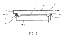
- the air tunnels may be integrally formed with small air pockets 22 (see Fig. 5) extending over and projecting laterally beyond the channels 7.
- An exception may be in the first tunnel 5 or so adjacent to the inlet end 9 where the tunnels extend over but not beyond the channels.
- the mattress body 3 may be made up of preformed top and bottom parts 23 and 25.
- the top part 23 is obtained from a plastic sheet blank 27 having a U-shaped slots 29 formed along opposite lateral edges.
- a tunnel 5 the sheet 27 is folded up along an axis 30 between two successive slots 29 until the tunnel 5 is obtained, having essentially the shape of an inverted U (see fig. 4), in cross-section, with a pair of straight spaced legs 31 and a dome-shaped bight 33.
- the opposed longitudinal edges of the blank 27 are then first bent down and then outwardly to form weld flanges 35.
- the so far shaped top part 23 is applied over the lower part 25 with the lower edges of the spaced legs 31 sitting squarely over the central portion 36 (between the air distribution channels 7) and welded thereto along weld lines 37, all of equal length across the mattress body 3.
- the central portion 36 then serves as flat bottoms for the tunnels 5.
- the unconnected edges of the ends of the tunnels 5 are then brought together, as shown by the horizontal arrows in fig. 3, and are welded to close the tunnels 5 which then communicate with the channels 7 and the plenum conduits 15 and 21.
- the two sheet parts 25, 27, are finally welded along their weld flanges 35, 35′.
- weld lines 37 across the central portion 36 of the bottom part 25 are all of equal length. Referring to fig. 2, in order then for the channels 7 to taper from the inlet end 15 to the terminal end 11, it is necessary that the lateral edges of the top and bottom parts 23, 25, more precisely the weld flanges 35, 35′, taper in between the ends 9 and 11, as shown.
- an air permeable and water imprevious sheet 37 (fig. 2) is applied over the mattress 1.
- the lower surface of sheet 37 consists of an air permeable hydrophobic urethane coating.
- the upper surface is made of a permeable woven textile material. Air necessary to reduce or prevent maceration comes from a plurality of bleed holes 39 (fig. 1) through the dome-shaped bights 33 of the tunnels 5.
- contoured end flaps 41, 43 are provided at the inlet end 9 and at the terminal end 11. They project down from the mattress bottom part 25 and extend across the ends 9, 11, as well as along a portion of the body 3 so as to tuck in the body 3 around the ends of a hospital bed mattress to firmly hold it in position thereon.
Abstract
Description
- The present invention relates to an inflatable air mattress used to improve the comfort of patients that are immobilized over long periods of time. The mattress of the invention can be used as such or be placed over the mattress of a conventional hospital bed and it is independent from it.
- For this type of patients, it is recommended to provide a mattress which is quite flexible throughout its length to prevent the creation of pressure points on parts of the patient's body that support its weight. These pressure points tend to cause occlusion of blood capillaries on the surface of the skin resulting in the development of body sores or skin rashes. The patent literature is replete with suggestions of mattress constructions intended to prevent this problem. While all of them seem to be based on the use of air inflatable mattresses, a very large number are more specifically adapting the principle of creating a ripple effect on the surface of the mattress, and consequently on the patient's body, to activate blood circulation. However, the known mattresses are quite complex in structure because of the presence of individual air circuits that are separately and alternatively supplied with pressure air and because of the complicated mechanical and electrical control system that is required to operate the mattress properly. These mattresses are consequently extremely costly.
- Patents known to the present applicants and addressing this subject are as follows:
U.S. Patents 945,234 - Hinsdale 3,303,518 - Ingram 3,644,950 - Linsay 3,653,083 - Lapidus 3,674,019 - Grant 3,678,520 - Evans 3,778,851 - Howorth 3,822,425 - Scales 3,879,776 - Solen 4,193,149 - Welch 4,224,706 - Young et al 4,225,989 - Corbett et al 4,297,755 - Mollura 4,346,489 - McMullan 4,394,784 - Swenson et al 4,525,885 - Hunt et al 4,542,547 - Sato 4,617,690 - Grebe 4,638,519 - Hess 4,686,722 - Swart U.K. Patents 1,273,342 - Hopkins 1,545,806 - Hopkins - An object of the present invention is to provide an inflatable air mattress in which air can be moved throughout its inner cavity without hindrance, in the manner of communicating vases, so that a pressure created by a particular portion of the patient's body is immediately transmitted to the complete air mass, thereby avoiding the creation of pressure spots.
- Another object is to provide a mattress having transverse air tunnel-like pillows supplied, at their ends, by lateral air distribution channels of which the cross-section decreases from the air inlet end to the terminal end of the mattress thereby providing uniform air pressure in all pillows regardless of their position with respect to the inlet end.
- Still another object of the invention lies in the provision of an inflated mattress which is directly connected to an adjustably controllable air compressor thereby avoiding the use of costly valves and/or cyclic switches or the like.
- Yet another object of the invention is that the ends of the pillows or air tunnels extend laterally outwardly of the lateral air distribution channels thereby making the patient's supporting surface wider than usual.
- More specifically and basically, the invention is an inflatable air mattress in the form of a one-piece elongated body made of flexible plastic material or air-retentative fabric and comprising, in inflated condition:
- a plurality of elongated parallel pillow-like straight air tunnels extending transversely of the body and disposed adjacent one another along essentially the full length of the body;
- a pair of air distribution channels located alongside the body and extending over essentially the full length thereof; each air tunnel having open ends and communicating with the distribution channels at its open ends, respectively, in order to be supplied with inflation air from the channels;
- wherein the body has an air inlet end and a terminal end away from the inlet end and wherein the distribution channels taper from the inlet end to the terminal end, having a cross-section that is larger at the inlet end that at the terminal end;
- an open-ended transverse plenum conduit at the inlet end, the conduit opening into the distribution channels, whereby the channels, the air tunnels and the plenum conduit communicate with one another, and
- air pressure source means operatively connected to the transverse plenum conduit to supply the conduit, the channels and the tunnels with pressure air. - Advantageously, each air tunnel may be integrally formed with a small air pocket at each end, said pocket extending over and covering the adjacent distribution channel to increase the width of the mattress.
- The above air pressure source means may advantageously comprise:
- a pressure-adjustable compressor assembly, and
- an air inlet conduit having one end connected to the compressor assembly and another end connected to the plenum chamber; the air-inlet conduit being devoid of air-flow control devices. - As mentioned above, and more specifically expressed, at least a major portion of the air tunnels should extend over and laterally beyond the distribution channels.
- Other features and advantages of the invention will be apparent from the description that follows, having reference to the appended drawings, in which
- Figure 1 is a perspective view of a mattress incorporating the features of the invention;
- Figure 2 is a top plan view of the mattress of Figure 1;
- Figure 3 is a perspective exploded view of part of the mattress; the upper section being shown in three different steps of its formation;
- Figure 4 is a longitudinal side elevation view, and
- Figure 5 is a cross-section at about mid-length of the mattress.
- The illustrated inflatable air mattress 1 is in the form of a one-piece
elongated body 3 entirely made of flexible plastic material, preferably vinyl or an urethane coated nylon such as DERMOFLEX® or of an air-retentative fabric. - The
body 3 comprises, in inflated condition, a series of elongated parallel pillow-likestraight air tunnels 5 that extend transversely of the body 1 and are disposed adjacent one another along essentially the full length of the body. In properly inflated condition, thetunnels 5 touch one another as best shown in Fig. 4. All obviously are of equal size and of constant cross-section. -
Tunnels 5 all communicate withair distribution channels 7 in order to be supplied with inflation air.Channels 7 extend the full length of the body 1, tapering from theair inlet end 9 of thebody 3 to itsterminal end 11, that is, having a greater cross-section at theinlet end 9 than at itsterminal end 11, as seen in Figures 2 and 3. With thetunnels 5 opening directly into bothchannels 7, tapering of the latter ensures constant pressure throughout themattress body 3 under the communicating vessels principle. Therefore, the above described structure allows all air pillows ortunnels 5 to be inflated at the same pressure regardless of their location with respect to theinlet end 9. Due to the excellent pressure distribution obtained with thetapering channels 7, the pressure output of the air supply unit, in this case thecompressor 17, to keep theair tunnels 5 properly inflated to support a patient's body may be as low as 5.5" of water as compared to 8" to 14" in conventional systems. - The
air distribution channels 7 are interconnected, at theinlet end 9, by atransverse plenum conduit 15. In this manner, theconduit 15, thechannels 7 and theair tunnels 5 all communicate with one another to form a series of closed air circulation circuits. - The
plenum conduit 15 is supplied with air under pressure by a pressure-adjustable compressor unit 17 connected to theplenum conduit 15 by aflexible hose 19. With this arrangement, the plenum conduit is in direct communication with thecompressor 17 and no valve assembly and/or cyclic switches or the like need be used thereby appreciably reducing the total cost of the mattress assembly, as aforesaid. - It will be appreciated that the
hose 19 may be connected to the first one of theair tunnels 5 which then replaces theplenum conduit 15. The result would be the same since thefirst tunnel 5 interconnects the twochannels 7. - The same reasoning applies at the
terminal end 11 of the mattress where aplenum conduit 21 is provided to join the relevant ends of thechannels 7. Again, thelast tunnel 5, at theterminal end 11, may be used as the plenum conduit. - As best shown in Figure 2, because of the tapering or narrowing down of the
air distribution channels 7 and to keep the mattress 1 of constant width, the air tunnels may be integrally formed with small air pockets 22 (see Fig. 5) extending over and projecting laterally beyond thechannels 7. An exception may be in thefirst tunnel 5 or so adjacent to theinlet end 9 where the tunnels extend over but not beyond the channels. - Referring now to Figures 2 and 3, the
mattress body 3 may be made up of preformed top andbottom parts - The
top part 23 is obtained from a plastic sheet blank 27 having aU-shaped slots 29 formed along opposite lateral edges. To obtain atunnel 5, thesheet 27 is folded up along anaxis 30 between twosuccessive slots 29 until thetunnel 5 is obtained, having essentially the shape of an inverted U (see fig. 4), in cross-section, with a pair of straightspaced legs 31 and a dome-shaped bight 33. With all thetunnels 5 thus shaped, the opposed longitudinal edges of the blank 27 are then first bent down and then outwardly to formweld flanges 35. Next, the so far shapedtop part 23 is applied over thelower part 25 with the lower edges of thespaced legs 31 sitting squarely over the central portion 36 (between the air distribution channels 7) and welded thereto alongweld lines 37, all of equal length across themattress body 3. Thecentral portion 36 then serves as flat bottoms for thetunnels 5. The unconnected edges of the ends of thetunnels 5 are then brought together, as shown by the horizontal arrows in fig. 3, and are welded to close thetunnels 5 which then communicate with thechannels 7 and theplenum conduits sheet parts weld flanges - As mentioned above, the
weld lines 37 across thecentral portion 36 of thebottom part 25 are all of equal length. Referring to fig. 2, in order then for thechannels 7 to taper from theinlet end 15 to theterminal end 11, it is necessary that the lateral edges of the top andbottom parts weld flanges ends - In order to avoid contamination of the mattress by the patient, an air permeable and water imprevious sheet 37 (fig. 2) is applied over the mattress 1. The lower surface of
sheet 37 consists of an air permeable hydrophobic urethane coating. The upper surface is made of a permeable woven textile material. Air necessary to reduce or prevent maceration comes from a plurality of bleed holes 39 (fig. 1) through the dome-shaped bights 33 of thetunnels 5. - Finally, and as illustrated in Figs. 4 and 5, contoured
end flaps 41, 43, are provided at theinlet end 9 and at theterminal end 11. They project down from themattress bottom part 25 and extend across theends body 3 so as to tuck in thebody 3 around the ends of a hospital bed mattress to firmly hold it in position thereon.
Claims (12)
an air inlet end (9);
a terminal end (11) longitudinally spaced from said air inlet end at the opposite end of said body;
an open-ended transverse plenum conduit (15) positioned in the interior of said body at said air inlet end;
a pair of air distribution channels (7), positioned in the interior of said body and extending longitudinally from said air inlet end to said terminal end, said air distribution channels being transversely separated from one another, located at substantially the outside perimeter of said body, being in communication with said plenum conduit, and having a configuration that tapers from a cross section that is larger at said air inlet end than at said terminal end;
a plurality of elongated parallel pillow-like straight air tunnels (5) extending transversely of said body and disposed adjacent one another along essentially the full length of said body, said air tunnels being sealed to said body along substantially all of their length and having an opening at each end thereof in communication with said respective ones of said air distribution channels in the interior of said body; and
a source (17) of air under pressure, operatively connected to said traverse plenum conduit, to thereby supply air to said distribution channels and said air tunnels.
- a pressure-adjustable compressor assembly (17), and
- an air inlet conduit (19) having one end connected to said compressor assembly and another end connected to said plenum chamber; said air-inlet conduit being devoid of air-flow control devices.
Applications Claiming Priority (2)
| Application Number | Priority Date | Filing Date | Title |
|---|---|---|---|
| CA569264 | 1988-06-10 | ||
| CA000569264A CA1328314C (en) | 1988-06-10 | 1988-06-10 | Inflatable air mattress |
Publications (3)
| Publication Number | Publication Date |
|---|---|
| EP0345973A2 true EP0345973A2 (en) | 1989-12-13 |
| EP0345973A3 EP0345973A3 (en) | 1990-05-02 |
| EP0345973B1 EP0345973B1 (en) | 1992-08-19 |
Family
ID=4138184
Family Applications (1)
| Application Number | Title | Priority Date | Filing Date |
|---|---|---|---|
| EP89305314A Expired - Lifetime EP0345973B1 (en) | 1988-06-10 | 1989-05-25 | Inflatable air mattress |
Country Status (6)
| Country | Link |
|---|---|
| US (1) | US4896389A (en) |
| EP (1) | EP0345973B1 (en) |
| JP (1) | JP2740549B2 (en) |
| CA (1) | CA1328314C (en) |
| DE (1) | DE68902510T2 (en) |
| ES (1) | ES2034632T3 (en) |
Cited By (3)
| Publication number | Priority date | Publication date | Assignee | Title |
|---|---|---|---|---|
| WO1990007891A1 (en) * | 1989-01-23 | 1990-07-26 | Afeyan Industries Inc. | Air mattress |
| WO2001012019A1 (en) * | 1999-08-13 | 2001-02-22 | Raoul Parienti | Retractable bed assembly with inflatable mattress |
| EP2500004A1 (en) * | 2008-11-06 | 2012-09-19 | Thaddée Mulliez | Inflatable cell of an anti-bedsore mattress |
Families Citing this family (74)
| Publication number | Priority date | Publication date | Assignee | Title |
|---|---|---|---|---|
| US5606754A (en) | 1989-03-09 | 1997-03-04 | Ssi Medical Services, Inc. | Vibratory patient support system |
| US5267363A (en) * | 1989-07-25 | 1993-12-07 | Chaffee Robert B | Pneumatic support system |
| US5584085A (en) * | 1989-08-24 | 1996-12-17 | Surgical Design Corporation | Support structure with motion |
| US6374436B1 (en) | 1994-01-25 | 2002-04-23 | Hill-Rom Services, Inc. | Hospital bed |
| US5680661A (en) * | 1990-05-16 | 1997-10-28 | Hill-Rom, Inc. | Hospital bed with user care apparatus |
| US5337845A (en) * | 1990-05-16 | 1994-08-16 | Hill-Rom Company, Inc. | Ventilator, care cart and motorized transport each capable of nesting within and docking with a hospital bed base |
| US5577279A (en) * | 1990-05-16 | 1996-11-26 | Hill-Rom Company, Inc. | Hospital bed |
| US5513406A (en) * | 1994-04-21 | 1996-05-07 | Hill-Rom Company, Inc. | Modular hospital bed and method of patient handling |
| US5483709A (en) * | 1994-04-01 | 1996-01-16 | Hill-Rom Company, Inc. | Low air loss mattress with rigid internal bladder and lower air pallet |
| US5561875A (en) * | 1992-02-20 | 1996-10-08 | Crown Therapeutics, Inc. | Vacuum/heat formed cushion supported on a fluid permeable manifold |
| US5594963A (en) * | 1992-08-20 | 1997-01-21 | Kinetic Concepts, Inc. | Pressure relief air mattress and related system |
| US5373595A (en) * | 1993-03-12 | 1994-12-20 | Irvin Industries Canada Ltd. | Air support device |
| US5539942A (en) * | 1993-12-17 | 1996-07-30 | Melou; Yves | Continuous airflow patient support with automatic pressure adjustment |
| US5586346A (en) | 1994-02-15 | 1996-12-24 | Support Systems, International | Method and apparatus for supporting and for supplying therapy to a patient |
| FR2718347B1 (en) * | 1994-04-06 | 1996-06-28 | Support Systems International | Method and apparatus for supporting an element to be supported, in particular the body of a patient allowing support at a controlled depth of penetration. |
| US5787531A (en) * | 1994-07-08 | 1998-08-04 | Pepe; Michael Francis | Inflatable pad or mattress |
| US5598593A (en) * | 1995-02-10 | 1997-02-04 | Aqua-Leisure Industries, Inc. | Inflatable air bed |
| US5647078A (en) | 1995-05-23 | 1997-07-15 | Dielectrics Industries | Control panel for an inflatable structure |
| US5906019A (en) * | 1995-10-31 | 1999-05-25 | Mccarthy; Kevin | Air mattress with oval beams |
| US5815865A (en) | 1995-11-30 | 1998-10-06 | Sleep Options, Inc. | Mattress structure |
| US5802646A (en) * | 1995-11-30 | 1998-09-08 | Hill-Rom, Inc. | Mattress structure having a foam mattress core |
| US6115861A (en) * | 1997-10-09 | 2000-09-12 | Patmark Company, Inc. | Mattress structure |
| US5794288A (en) * | 1996-06-14 | 1998-08-18 | Hill-Rom, Inc. | Pressure control assembly for an air mattress |
| US6012186A (en) | 1997-04-29 | 2000-01-11 | Hill-Rom Compnay, Inc. | Mattress articulation structure |
| WO1999049761A1 (en) | 1998-03-31 | 1999-10-07 | Hill-Rom, Inc. | Air-over-foam mattress |
| US6269504B1 (en) | 1998-05-06 | 2001-08-07 | Hill-Rom Services, Inc. | Mattress or cushion structure |
| US7191482B2 (en) | 1998-05-06 | 2007-03-20 | Hill Rom Services, Inc. | Patient support |
| US9462893B2 (en) | 1998-05-06 | 2016-10-11 | Hill-Rom Services, Inc. | Cover system for a patient support surface |
| US7174589B2 (en) * | 2000-05-03 | 2007-02-13 | Trlby Innovative Llc | Inflatable cushion systems and method of manufacture thereof |
| US6775868B1 (en) * | 2000-05-03 | 2004-08-17 | Trlby Innovative Llc | Inflatable mattress systems and method of manufacture thereof |
| US7025576B2 (en) | 2001-03-30 | 2006-04-11 | Chaffee Robert B | Pump with axial conduit |
| US6457192B2 (en) | 2000-10-04 | 2002-10-01 | Harrison Choi | Air bed with elevated and self-expanding support structure |
| ATE454120T1 (en) | 2000-11-07 | 2010-01-15 | Tempur World Llc | THERAPEUTIC MATTRESS ARRANGEMENT |
| US7152264B2 (en) * | 2001-03-30 | 2006-12-26 | Dennis Boyd | Air mattress with pillow top |
| US7610642B2 (en) * | 2001-03-30 | 2009-11-03 | Dennis Boyd | Air mattress with pillow top |
| RU2271129C2 (en) * | 2001-03-30 | 2006-03-10 | Роберт Б. ШАФФЕ | Inflatable apparatus with deepened fluid control means and control panel |
| US6983502B2 (en) | 2001-03-30 | 2006-01-10 | Boyd Flotation, Inc. | Air mattress with pillow top |
| US6665893B2 (en) * | 2001-04-06 | 2003-12-23 | L & P Property Management Company | Sofa sleeper with integral air mattress and valve |
| CA2453240C (en) | 2001-07-10 | 2011-08-30 | Robert Chaffee | Configurable inflatable support devices |
| US6701559B2 (en) | 2001-08-01 | 2004-03-09 | Aero Products International, Inc. | Increased height inflatable support system |
| US7478448B2 (en) * | 2001-08-01 | 2009-01-20 | Aero Products International, Inc. | Inflatable reinforcing chamber |
| US6855158B2 (en) | 2001-09-11 | 2005-02-15 | Hill-Rom Services, Inc. | Thermo-regulating patient support structure |
| DE10151984C5 (en) * | 2001-10-22 | 2008-07-17 | Map Medizin-Technologie Gmbh | Application device for a breathing mask arrangement |
| US6839929B2 (en) | 2001-12-13 | 2005-01-11 | Hill-Rom Services, Inc. | Self-sealing mattress structure |
| CA2482164C (en) * | 2002-04-11 | 2012-03-06 | Robert B. Chaffee | Body support surface comfort device |
| US7000276B2 (en) * | 2002-04-11 | 2006-02-21 | Chaffee Robert B | Body support surface comfort device |
| CN101254053A (en) * | 2002-04-25 | 2008-09-03 | 罗伯特·B·查飞 | Inflatable chambers fluidly connected by one way valve and method for use |
| CN1329684C (en) | 2002-05-03 | 2007-08-01 | 罗伯特·B·查飞 | Self-sealing valve with electromechanical device for actuating the valve |
| AU2003252032A1 (en) * | 2002-07-18 | 2004-02-09 | George Matthews | Universal earth suit |
| MXPA05005493A (en) | 2002-11-18 | 2005-09-08 | B Chaffee Robert | Inflatable device. |
| US20040128772A1 (en) * | 2002-12-19 | 2004-07-08 | Branson Gregory W. | Patient support surface |
| WO2005000074A1 (en) * | 2003-06-09 | 2005-01-06 | Aero International Products, Inc. | Reversible inflation system |
| GB0503159D0 (en) * | 2005-02-16 | 2005-03-23 | Teasdale Hospital Equipment Lt | An inflatable component for an alternating pressure mattress |
| US7588425B2 (en) * | 2005-03-18 | 2009-09-15 | Aero Products International, Inc. | Reversible inflation system |
| US7469437B2 (en) | 2005-06-24 | 2008-12-30 | Tempur-Pedic Management, Inc. | Reticulated material body support and method |
| US20070033739A1 (en) * | 2005-08-12 | 2007-02-15 | Austen Timothy F | Inflatable support system having thermoplastic polyurethane construction |
| US20070056114A1 (en) * | 2005-09-09 | 2007-03-15 | Corey Lewison | Multi-zone coil construction airbed |
| FR2907646B1 (en) * | 2006-10-26 | 2009-02-06 | Hill Rom Ind S A Sa | DEVICE AND METHOD FOR CONTROLLING MOISTURE AT THE SURFACE OF A MATTRESS TYPE SUPPORT ELEMENT. |
| US7849545B2 (en) | 2006-11-14 | 2010-12-14 | Hill-Rom Industries Sa | Control system for hospital bed mattress |
| US7653954B2 (en) * | 2006-12-20 | 2010-02-02 | Hill-Rom Services, Inc. | Lift system for a patient-support apparatus |
| US8108957B2 (en) * | 2007-05-31 | 2012-02-07 | Hill-Rom Services, Inc. | Pulmonary mattress |
| FR2922427B1 (en) | 2007-10-18 | 2013-03-29 | Hill Rom Ind Sa | INFLATABLE CELL, MANUFACTURING METHOD AND SUPPORTING DEVICE HAVING THE SAME |
| US8051516B2 (en) | 2008-07-30 | 2011-11-08 | Micropulse, Inc. | Clinical support pad |
| US8490226B2 (en) | 2008-09-19 | 2013-07-23 | Diacor, Inc. | Systems for patient transfer, devices for movement of a patient, and methods for transferring a patient for treatment |
| US8151391B2 (en) * | 2008-09-23 | 2012-04-10 | Jacobo Frias | Inflatable temperature control system |
| US7694372B1 (en) | 2009-04-07 | 2010-04-13 | Dennis Boyd | Air mattress |
| FR2949320B1 (en) * | 2009-08-31 | 2012-11-16 | Hill Rom Ind Sa | LATERAL TILT DEVICE |
| US9381127B2 (en) * | 2010-02-26 | 2016-07-05 | Matthew T. Scholz | Patient support systems and methods for transferring patients and controlling patient temperature |
| GB201114081D0 (en) * | 2011-08-16 | 2011-09-28 | Invacare Uk Operations Ltd | Pressure relieving mattress |
| US10166160B2 (en) * | 2012-02-21 | 2019-01-01 | Qfix Systems, Llc | Air bearing device and method for transferring patients |
| US9504620B2 (en) | 2014-07-23 | 2016-11-29 | American Sterilizer Company | Method of controlling a pressurized mattress system for a support structure |
| US10413464B2 (en) | 2015-05-05 | 2019-09-17 | Hill-Rom Services, Inc. | Multi-mode sacral unloading pressure relief in a patient support surface |
| US9919229B1 (en) * | 2017-05-10 | 2018-03-20 | Sarmen Bagumyan | Inflatable landing pad for use with an inflatable play structure |
| US11071393B2 (en) | 2017-10-04 | 2021-07-27 | Hill-Rom Services, Inc. | Apparatus for adding hospital bed functionality to an at-home bed |
Citations (4)
| Publication number | Priority date | Publication date | Assignee | Title |
|---|---|---|---|---|
| FR774679A (en) * | 1933-06-08 | 1934-12-11 | Air mattress for camping | |
| FR2127928A5 (en) * | 1971-03-02 | 1972-10-13 | Howorth Air Conditioning Ltd | |
| US4391009A (en) * | 1980-10-17 | 1983-07-05 | Huntleigh Medical Ltd. | Ventilated body support |
| DE3320771A1 (en) * | 1983-06-09 | 1984-12-13 | Fritz 8942 Ottobeuren Noack | Pneumatic mattress |
Family Cites Families (33)
| Publication number | Priority date | Publication date | Assignee | Title |
|---|---|---|---|---|
| CA608979A (en) * | 1960-11-22 | J. Edwards Orley | Self-inflating articles | |
| US945234A (en) * | 1908-12-12 | 1910-01-04 | Hinsdale Pneumatic Cushion And Mattress Company | Pneumatic mattress. |
| US1830570A (en) * | 1929-09-09 | 1931-11-03 | Smith William Henry | Pneumatic upholstery |
| FR841703A (en) * | 1937-11-16 | 1939-05-25 | Wetzell Gummiwerke Ag | Inflatable mattress |
| US2816299A (en) * | 1954-07-12 | 1957-12-17 | Holladay Tool Res | Surf float |
| US3056980A (en) * | 1958-04-23 | 1962-10-09 | Forrest E Holladay | Plastic sheeting articles and manufacture |
| GB969367A (en) * | 1962-03-05 | 1964-09-09 | George Ingram | Improvements in inflatable mattresses, pillows and cushions |
| FR1442492A (en) * | 1965-05-06 | 1966-06-17 | Advanced air mattress | |
| GB1273342A (en) * | 1968-01-31 | 1972-05-10 | Nat Res Dev | Improvements relating to fluid mattresses |
| US3644950A (en) * | 1969-08-01 | 1972-02-29 | Milton Roy Co | Patient support system |
| GB1286197A (en) * | 1970-03-13 | 1972-08-23 | Ronald James Peter Evans | Improvements in or relating to alternating pressure pads for bed patients |
| US3653083A (en) * | 1970-05-11 | 1972-04-04 | Roy Lapidus | Bed pad |
| US3672354A (en) * | 1970-09-04 | 1972-06-27 | Scovill Manufacturing Co | Rest-inducing device |
| US3674019A (en) * | 1970-10-23 | 1972-07-04 | Grant Airmass Corp | Dual layer cellular inflatable pad |
| GB1341325A (en) * | 1971-07-09 | 1973-12-19 | Scales J T | Inflatable support appliance |
| US3879776A (en) * | 1974-01-10 | 1975-04-29 | Morris Solen | Variable tension fluid mattress |
| GB1545806A (en) * | 1976-09-23 | 1979-05-16 | Hopkins L | Fluid mattresses |
| FR2373996A1 (en) * | 1976-12-14 | 1978-07-13 | Roger Tallon | Fluid filled bed or chair - has flexible envelopes connected to tubular frame which forms manifold |
| GB1595417A (en) * | 1977-03-29 | 1981-08-12 | Welch H G | Beds and mattresses |
| US4225989A (en) * | 1978-10-05 | 1980-10-07 | Glynwed Group Services Limited | Inflatable supports |
| US4224706A (en) * | 1978-10-16 | 1980-09-30 | Dial-A-Firm, Inc. | Pneumatic bed |
| US4297755A (en) * | 1980-02-15 | 1981-11-03 | Mollura Carlos A | Non-planar waterbed |
| GB2070174A (en) * | 1980-02-26 | 1981-09-03 | Watkins & Watson Ltd | Conduit connector |
| US4346489A (en) * | 1980-06-03 | 1982-08-31 | Mcmullan James P | Foldable waterbed |
| US4394784A (en) * | 1981-07-08 | 1983-07-26 | Dial-A-Firm International, Inc. | Air bed with firmness control |
| JPS5993524U (en) * | 1982-12-15 | 1984-06-25 | 狩野 千世子 | Air mat type bed operated by computer |
| NL8301197A (en) * | 1983-04-06 | 1984-11-01 | Stichting Revalidatie Inst | LY SUPPORT COMPRISING A COMBINATION OF MULTIPLE PILLOWS, NOT LIGHT OR LEAKS, WITH A SPECIFIC PRESSURE MEASUREMENT AND CONTROL SYSTEM. |
| US4644597A (en) * | 1983-05-09 | 1987-02-24 | Dynatech, Inc. | Air mattress with pressure relief valve |
| GB8315448D0 (en) * | 1983-06-06 | 1983-07-13 | Mediscus Prod Ltd | Low air loss support applications |
| US4617690A (en) * | 1985-01-07 | 1986-10-21 | Whittaker Corporation | Inflatable bed patient mattress |
| US4638519A (en) * | 1985-04-04 | 1987-01-27 | Air Plus, Inc. | Fluidized hospital bed |
| US4745647A (en) * | 1985-12-30 | 1988-05-24 | Ssi Medical Services, Inc. | Patient support structure |
| US4694520A (en) * | 1986-01-15 | 1987-09-22 | Ssi Medical Services, Inc. | Patient support apparatus |
-
1988
- 1988-06-10 US US07/204,732 patent/US4896389A/en not_active Expired - Lifetime
- 1988-06-10 CA CA000569264A patent/CA1328314C/en not_active Expired - Fee Related
-
1989
- 1989-05-25 ES ES198989305314T patent/ES2034632T3/en not_active Expired - Lifetime
- 1989-05-25 EP EP89305314A patent/EP0345973B1/en not_active Expired - Lifetime
- 1989-05-25 DE DE8989305314T patent/DE68902510T2/en not_active Expired - Fee Related
- 1989-06-09 JP JP1145531A patent/JP2740549B2/en not_active Expired - Fee Related
Patent Citations (4)
| Publication number | Priority date | Publication date | Assignee | Title |
|---|---|---|---|---|
| FR774679A (en) * | 1933-06-08 | 1934-12-11 | Air mattress for camping | |
| FR2127928A5 (en) * | 1971-03-02 | 1972-10-13 | Howorth Air Conditioning Ltd | |
| US4391009A (en) * | 1980-10-17 | 1983-07-05 | Huntleigh Medical Ltd. | Ventilated body support |
| DE3320771A1 (en) * | 1983-06-09 | 1984-12-13 | Fritz 8942 Ottobeuren Noack | Pneumatic mattress |
Cited By (4)
| Publication number | Priority date | Publication date | Assignee | Title |
|---|---|---|---|---|
| WO1990007891A1 (en) * | 1989-01-23 | 1990-07-26 | Afeyan Industries Inc. | Air mattress |
| WO2001012019A1 (en) * | 1999-08-13 | 2001-02-22 | Raoul Parienti | Retractable bed assembly with inflatable mattress |
| FR2798050A1 (en) * | 1999-08-13 | 2001-03-09 | Raoul Parienti | RETRACTABLE BED SET (S) WITH INFLATABLE MATTRESS |
| EP2500004A1 (en) * | 2008-11-06 | 2012-09-19 | Thaddée Mulliez | Inflatable cell of an anti-bedsore mattress |
Also Published As
| Publication number | Publication date |
|---|---|
| DE68902510T2 (en) | 1993-03-11 |
| ES2034632T3 (en) | 1993-04-01 |
| JPH02237563A (en) | 1990-09-20 |
| JP2740549B2 (en) | 1998-04-15 |
| EP0345973A3 (en) | 1990-05-02 |
| DE68902510D1 (en) | 1992-09-24 |
| US4896389A (en) | 1990-01-30 |
| CA1328314C (en) | 1994-04-05 |
| EP0345973B1 (en) | 1992-08-19 |
Similar Documents
| Publication | Publication Date | Title |
|---|---|---|
| EP0345973A2 (en) | Inflatable air mattress | |
| US4391009A (en) | Ventilated body support | |
| US5109560A (en) | Ventilated air mattress with alternately inflatable air cells having communicating upper and lower air chambers | |
| US5956787A (en) | Anti-decubitus pneumatic mattress | |
| EP0897684B1 (en) | Inflatable support | |
| US4999867A (en) | Air mattress and method for adjusting it | |
| US10722041B2 (en) | Air-powered low interface pressure overlay | |
| US5367728A (en) | Adjustable ventilation mattress | |
| US6367106B1 (en) | Therapeutic support for the reduction of decubitus ulcers | |
| US6085372A (en) | Anti-decubitus pneumatic mattress | |
| CA1304838C (en) | Fluid pressurized cushion | |
| EP0025701A2 (en) | Support | |
| US4864671A (en) | Controllably inflatable cushion | |
| US5373595A (en) | Air support device | |
| US5634225A (en) | Modular air bed | |
| US5113539A (en) | Adjustable firmness coil spring mattress with inflatable tubes | |
| US4777679A (en) | Inflatable cushion with central opening | |
| US9717638B2 (en) | Self-powered microclimate controlled mattress | |
| US5586348A (en) | Air mattress and method for adjusting it | |
| GB1576641A (en) | Pressure point pads | |
| US6122786A (en) | Inflatable mattresses | |
| JP4131522B2 (en) | Patient support | |
| EP0993818A2 (en) | Inflatable patient supports | |
| JPH0451787Y2 (en) | ||
| JPS62181044A (en) | Therapeutic air mat |
Legal Events
| Date | Code | Title | Description |
|---|---|---|---|
| PUAI | Public reference made under article 153(3) epc to a published international application that has entered the european phase |
Free format text: ORIGINAL CODE: 0009012 |
|
| AK | Designated contracting states |
Kind code of ref document: A2 Designated state(s): BE CH DE ES FR GB IT LI LU NL |
|
| PUAL | Search report despatched |
Free format text: ORIGINAL CODE: 0009013 |
|
| AK | Designated contracting states |
Kind code of ref document: A3 Designated state(s): BE CH DE ES FR GB IT LI LU NL |
|
| 17P | Request for examination filed |
Effective date: 19900619 |
|
| 17Q | First examination report despatched |
Effective date: 19910716 |
|
| GRAA | (expected) grant |
Free format text: ORIGINAL CODE: 0009210 |
|
| AK | Designated contracting states |
Kind code of ref document: B1 Designated state(s): BE CH DE ES FR GB IT LI LU NL |
|
| ITF | It: translation for a ep patent filed |
Owner name: AVV. SALVATORE LA CIURA |
|
| REF | Corresponds to: |
Ref document number: 68902510 Country of ref document: DE Date of ref document: 19920924 |
|
| RAP2 | Party data changed (patent owner data changed or rights of a patent transferred) |
Owner name: HILLENBRAND INDUSTRIES CANADA LIMITED |
|
| REG | Reference to a national code |
Ref country code: CH Ref legal event code: PUE Owner name: HILLENBRAND INDUSTRIES CANADA LIMITED |
|
| ET | Fr: translation filed | ||
| REG | Reference to a national code |
Ref country code: ES Ref legal event code: FG2A Ref document number: 2034632 Country of ref document: ES Kind code of ref document: T3 |
|
| PLBE | No opposition filed within time limit |
Free format text: ORIGINAL CODE: 0009261 |
|
| STAA | Information on the status of an ep patent application or granted ep patent |
Free format text: STATUS: NO OPPOSITION FILED WITHIN TIME LIMIT |
|
| 26N | No opposition filed | ||
| EPTA | Lu: last paid annual fee | ||
| REG | Reference to a national code |
Ref country code: GB Ref legal event code: IF02 |
|
| PGFP | Annual fee paid to national office [announced via postgrant information from national office to epo] |
Ref country code: CH Payment date: 20020503 Year of fee payment: 14 |
|
| PGFP | Annual fee paid to national office [announced via postgrant information from national office to epo] |
Ref country code: ES Payment date: 20020606 Year of fee payment: 14 |
|
| PG25 | Lapsed in a contracting state [announced via postgrant information from national office to epo] |
Ref country code: ES Free format text: LAPSE BECAUSE OF NON-PAYMENT OF DUE FEES Effective date: 20030526 |
|
| PG25 | Lapsed in a contracting state [announced via postgrant information from national office to epo] |
Ref country code: LI Free format text: LAPSE BECAUSE OF NON-PAYMENT OF DUE FEES Effective date: 20030531 Ref country code: CH Free format text: LAPSE BECAUSE OF NON-PAYMENT OF DUE FEES Effective date: 20030531 |
|
| PGFP | Annual fee paid to national office [announced via postgrant information from national office to epo] |
Ref country code: LU Payment date: 20030605 Year of fee payment: 15 |
|
| PGFP | Annual fee paid to national office [announced via postgrant information from national office to epo] |
Ref country code: BE Payment date: 20030613 Year of fee payment: 15 |
|
| REG | Reference to a national code |
Ref country code: CH Ref legal event code: PL |
|
| PGFP | Annual fee paid to national office [announced via postgrant information from national office to epo] |
Ref country code: NL Payment date: 20040429 Year of fee payment: 16 |
|
| PGFP | Annual fee paid to national office [announced via postgrant information from national office to epo] |
Ref country code: GB Payment date: 20040519 Year of fee payment: 16 Ref country code: FR Payment date: 20040519 Year of fee payment: 16 |
|
| PG25 | Lapsed in a contracting state [announced via postgrant information from national office to epo] |
Ref country code: LU Free format text: LAPSE BECAUSE OF NON-PAYMENT OF DUE FEES Effective date: 20040525 |
|
| PG25 | Lapsed in a contracting state [announced via postgrant information from national office to epo] |
Ref country code: BE Free format text: LAPSE BECAUSE OF NON-PAYMENT OF DUE FEES Effective date: 20040531 |
|
| PGFP | Annual fee paid to national office [announced via postgrant information from national office to epo] |
Ref country code: DE Payment date: 20040630 Year of fee payment: 16 |
|
| REG | Reference to a national code |
Ref country code: ES Ref legal event code: FD2A Effective date: 20030526 |
|
| BERE | Be: lapsed |
Owner name: *HILLENBRAND INDUSTRIES CANADA LTD Effective date: 20040531 |
|
| PG25 | Lapsed in a contracting state [announced via postgrant information from national office to epo] |
Ref country code: IT Free format text: LAPSE BECAUSE OF NON-PAYMENT OF DUE FEES;WARNING: LAPSES OF ITALIAN PATENTS WITH EFFECTIVE DATE BEFORE 2007 MAY HAVE OCCURRED AT ANY TIME BEFORE 2007. THE CORRECT EFFECTIVE DATE MAY BE DIFFERENT FROM THE ONE RECORDED. Effective date: 20050525 Ref country code: GB Free format text: LAPSE BECAUSE OF NON-PAYMENT OF DUE FEES Effective date: 20050525 |
|
| PG25 | Lapsed in a contracting state [announced via postgrant information from national office to epo] |
Ref country code: NL Free format text: LAPSE BECAUSE OF NON-PAYMENT OF DUE FEES Effective date: 20051201 Ref country code: DE Free format text: LAPSE BECAUSE OF NON-PAYMENT OF DUE FEES Effective date: 20051201 |
|
| GBPC | Gb: european patent ceased through non-payment of renewal fee |
Effective date: 20050525 |
|
| PG25 | Lapsed in a contracting state [announced via postgrant information from national office to epo] |
Ref country code: FR Free format text: LAPSE BECAUSE OF NON-PAYMENT OF DUE FEES Effective date: 20060131 |
|
| NLV4 | Nl: lapsed or anulled due to non-payment of the annual fee |
Effective date: 20051201 |
|
| REG | Reference to a national code |
Ref country code: FR Ref legal event code: ST Effective date: 20060131 |