EP0346631B1 - Detergent dispensing device for dishwashing machines - Google Patents
Detergent dispensing device for dishwashing machines Download PDFInfo
- Publication number
- EP0346631B1 EP0346631B1 EP89108821A EP89108821A EP0346631B1 EP 0346631 B1 EP0346631 B1 EP 0346631B1 EP 89108821 A EP89108821 A EP 89108821A EP 89108821 A EP89108821 A EP 89108821A EP 0346631 B1 EP0346631 B1 EP 0346631B1
- Authority
- EP
- European Patent Office
- Prior art keywords
- fact
- wall
- tongues
- fastening frame
- dispensing device
- Prior art date
- Legal status (The legal status is an assumption and is not a legal conclusion. Google has not performed a legal analysis and makes no representation as to the accuracy of the status listed.)
- Expired - Lifetime
Links
- 239000003599 detergent Substances 0.000 title claims description 11
- 238000004851 dishwashing Methods 0.000 title description 7
- 210000002105 tongue Anatomy 0.000 claims description 18
- 230000002093 peripheral effect Effects 0.000 claims description 13
- 230000000284 resting effect Effects 0.000 claims 1
- 238000005406 washing Methods 0.000 description 3
- 238000007789 sealing Methods 0.000 description 2
- 230000006978 adaptation Effects 0.000 description 1
- 238000005452 bending Methods 0.000 description 1
- 238000001816 cooling Methods 0.000 description 1
- 238000013016 damping Methods 0.000 description 1
- 238000006073 displacement reaction Methods 0.000 description 1
- 230000000694 effects Effects 0.000 description 1
- 238000010438 heat treatment Methods 0.000 description 1
- 238000003780 insertion Methods 0.000 description 1
- 230000037431 insertion Effects 0.000 description 1
- 239000007788 liquid Substances 0.000 description 1
- 239000000463 material Substances 0.000 description 1
- 239000000843 powder Substances 0.000 description 1
- 230000002787 reinforcement Effects 0.000 description 1
Images
Classifications
-
- A—HUMAN NECESSITIES
- A47—FURNITURE; DOMESTIC ARTICLES OR APPLIANCES; COFFEE MILLS; SPICE MILLS; SUCTION CLEANERS IN GENERAL
- A47L—DOMESTIC WASHING OR CLEANING; SUCTION CLEANERS IN GENERAL
- A47L15/00—Washing or rinsing machines for crockery or tableware
- A47L15/42—Details
- A47L15/44—Devices for adding cleaning agents; Devices for dispensing cleaning agents, rinsing aids or deodorants
Definitions
- the invention concerns a dispensing device for liquid or powder detergents, which is apt to be fitted in an aperture provided in an internal wall of a wash chamber, in particular in the internal wall of the loading door of a dishwasher or similar machine, the device having the features defined in the preamble of Claim 1.
- a detergent dispensing device in which reversaly oriented and elastically yielding tongue means are provided on the outer walls of the detergent container, which engage the turned down edge of an aperture in a wall portion of the washing machine and cooperate with an oppositely oriented peripheral edge of the same container to retain the same in the aperture of the wall of said machine.
- no means are provided to prevent the yielding of the retaining tongues and their deformation caused during the use of the washing machine, therefore no firm fastening of the device is allowed.
- a fastening device for fastening an apparatus to an aperture of a wall, preventing axial displacement of the apparatus; rearwar oriented hooking tongues are formed on the front face of the apparatus to cooperate with cam means are provided on a shoulder of the same apparatus and a rotatable annular member to lock said apparatus against the wall.
- the fastening device according to FR-A-2.541.738 does not allow automatic fitting of the apparatus and therefore could not be used in combination with different snap-hooking device.
- an object of the invention is to provide a detergent dispensing device for dishwashing machines, which is provided with snap-fitting means allowing a firm and reliable fitting in an aperture of a wall of the washing chamber of the machine.
- a further object of this invention is to provide a dispensing device, as defined above, which is provided with fastening means allowing a fully automatic fitting of the device that can withstand to stress or deformations of plastic material, caused by repeated thermal cycles during use of the machine.
- a detergent dispensing device for dishwashers or similar machines comprising fastening means for its fitting in an aperture of an internal wall of a wash chamber, in particular in the wall of the loading and unloading door of a dishwasher, according to claim 1.
- reference 10 indicates a general type of detergent dispensing device fitted in an aperture provided in an internal wall 11 of the wash chamber of a dishwashing machine; as shown in figure 2, the aperture in the wall 11 of the chamber, has inwardly bent peripheral edges 12 to which the dispensing de vice 10 is attached, though the bent edges 12 may be omitted.
- the device 10 usually comprises a body defining the trays for the detergent, said body being delimited by lateral walls 13 provided with a laterally which extend from an outwardly protruding outer peripheral edge 14 on the body of the dispensing device 10.
- the body 10 of the dispensing device comprises a plurality of elastically flexible damping tongues 15 which are arranged parallel to the lateral walls 13 and positioned at a short distance from the peripheral edge 14 of the body.
- Each tongue 15 is rearwardly directed and protruding towards inside from the peripheral edge 14 and comprises an enlarged head 16 having a step-shaped front portion 17 and an inclined surface 18 to facilitate and enable the automatic insertion of the device through the aperture in the wall 11 by partially elastically bending tougues 15 towards the wall 13 of the body 10.
- reference number 19 indicates a sealing gasket which is disposed between the wall 11 of the dishwashing machine and the flange 14 of the dispensing device.
- the fastening means of the device also comprise a peripheral frame 20, or equivalent element, which partly or totally surrounds the body of the dispensing device.
- the frame 20 has a flat base portion 21 which come into contact with the internal face of the wall 11 which is opposite the one in contact with the sealing gasket 19, as well as comprises one or more elastically flexible lugs 22 which will come into contact with the step-shaped front surface 17, of the enlarged head 16 of the flexible tongues 15 attaching the dispensing device to the aperture of the wash chamber wall 11.
- each flexible lug 22 of the fastening frame has a protruding edge portion 23, of triangular shape, which will engage of be brought into contact with the corresponding opposing flexible tongue 15 of the dispensing device.
- the fastening frame 20 comprises a clamping strip 24 suitably spaced from the lugs 22, which is wedged with a certain pressure into the gap 25 between the opposing faces of a lateral wall 13 of the body 10 of the dispensing device and the aforesaid clamping tongues 15.
- the fastening frame 20 is prevented from being displaced, thereby guaranteeing a fastening arrangement that is practical and secure in use and which remains such even when the whole device is subject to repeated heating and cooling cycles, as normally happens during use of the relevant dishwashing machines.
- the particular staggered positioning of the clamping strip 24 and the fastening frame 20 has the effect that any force or action tending to make the frame 20 rotate will always cause the latter to adhere still more both against the tongues 15 of the dispensing device and against the wall 11 of the wash chamber of the machine.
- a preferred embodiment of the fastening frame 20 is shown in the views in figures 3 to 5.
- the frame 20 takes the form of a rectangular frame, in two separate parts 20a and 20b that will fit around the entire body of the dispensing device, on four sides.
- Each half 20a and 20b of the frame essentially comprises one channel-shaped element 26 having inner wall provided with a plurality of elastically flexible lugs 22 and a strip or strip portions 24 having reinforcement bridging web member to give the channel the requisite rigidity.
- Each clamping lug 22, as previously described, has an triangular-shaped edge 23 which will engage with the steps 17 of the enlarged head 16 of a matching tongue of the dispensing device.
- the design of the clamping frame in two parts is advantageous because it facilitates easy adaptation to any practical needs that may be encountered in fitting the dispensing devices in question.
- the frame part 20b illustrated by dashed lines in figure 3 is identical in shape to the frame part 20a shown by a continuous lines.
- the frame 20 surrounds the whole periphery of the body 10 of the dispensing device although the clamping frame could be limited so as to attach only onto two opposing sides or walls of the device, or only along a part of them, without however thereby departing from the innovative principles claimed for this invention.
Description
- The invention concerns a dispensing device for liquid or powder detergents, which is apt to be fitted in an aperture provided in an internal wall of a wash chamber, in particular in the internal wall of the loading door of a dishwasher or similar machine, the device having the features defined in the preamble of
Claim 1. - Currently used detergent dispensing devices for dishwashing machines are fitted into an aperture formed in an internal wall of the wash chamber by means, for example, of screws or similar fasteners, or by using attachment systems which have proved to be mostly unreliable and ill-suited to the various conditions of use and which, in addition, make no provision for a totally automatic fitting.
- From EP-A-0207520 a detergent dispensing device is known, in which reversaly oriented and elastically yielding tongue means are provided on the outer walls of the detergent container, which engage the turned down edge of an aperture in a wall portion of the washing machine and cooperate with an oppositely oriented peripheral edge of the same container to retain the same in the aperture of the wall of said machine. In said device no means are provided to prevent the yielding of the retaining tongues and their deformation caused during the use of the washing machine, therefore no firm fastening of the device is allowed. From FR-A-2.541.738 a fastening device is known for fastening an apparatus to an aperture of a wall, preventing axial displacement of the apparatus; rearwar oriented hooking tongues are formed on the front face of the apparatus to cooperate with cam means are provided on a shoulder of the same apparatus and a rotatable annular member to lock said apparatus against the wall. The fastening device according to FR-A-2.541.738 does not allow automatic fitting of the apparatus and therefore could not be used in combination with different snap-hooking device.
- Accordingly, an object of the invention is to provide a detergent dispensing device for dishwashing machines, which is provided with snap-fitting means allowing a firm and reliable fitting in an aperture of a wall of the washing chamber of the machine.
- A further object of this invention is to provide a dispensing device, as defined above, which is provided with fastening means allowing a fully automatic fitting of the device that can withstand to stress or deformations of plastic material, caused by repeated thermal cycles during use of the machine.
- The above-stated requirements can be obtained by means of a detergent dispensing device for dishwashers or similar machines, comprising fastening means for its fitting in an aperture of an internal wall of a wash chamber, in particular in the wall of the loading and unloading door of a dishwasher, according to
claim 1. - The invention will be described hereunder with reference to the example shown in the appended drawings, in which:
- Fig. 1
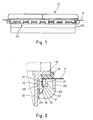
- is a front view of a detergent dispensing device fitted in a wall of a wash chamber of a dishwashing machine, according to the invention;
- Fig. 2
- is a sectional view of an enlarged detail of figure 1;
- Fig. 3
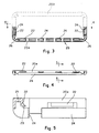
- is a top view of a particular embodiment of a peripheral fastening frame for the dispensing device of figure 1;
- Fig. 4
- is a view along the line 4-4 of figure 3;
- Fig. 5
- is an enlarged sectional view along the line 5-5 of figure 4.
- In figure 1
reference 10 indicates a general type of detergent dispensing device fitted in an aperture provided in aninternal wall 11 of the wash chamber of a dishwashing machine; as shown in figure 2, the aperture in thewall 11 of the chamber, has inwardly bentperipheral edges 12 to which the dispensing device 10 is attached, though thebent edges 12 may be omitted. - The
device 10 usually comprises a body defining the trays for the detergent, said body being delimited bylateral walls 13 provided with a laterally which extend from an outwardly protruding outerperipheral edge 14 on the body of thedispensing device 10. - Along at least two opposite
lateral walls 13, on the outside and from aperipheral edge 14, thebody 10 of the dispensing device comprises a plurality of elasticallyflexible damping tongues 15 which are arranged parallel to thelateral walls 13 and positioned at a short distance from theperipheral edge 14 of the body. Eachtongue 15 is rearwardly directed and protruding towards inside from theperipheral edge 14 and comprises an enlargedhead 16 having a step-shaped front portion 17 and aninclined surface 18 to facilitate and enable the automatic insertion of the device through the aperture in thewall 11 by partially elastically bendingtougues 15 towards thewall 13 of thebody 10. Additionally,reference number 19 indicates a sealing gasket which is disposed between thewall 11 of the dishwashing machine and theflange 14 of the dispensing device. - The fastening means of the device, as shown in figure 1 and in the detail in figure 2, also comprise a
peripheral frame 20, or equivalent element, which partly or totally surrounds the body of the dispensing device. As may be seen in the enlarged detail of figure 2, theframe 20 has aflat base portion 21 which come into contact with the internal face of thewall 11 which is opposite the one in contact with the sealinggasket 19, as well as comprises one or more elasticallyflexible lugs 22 which will come into contact with the step-shaped front surface 17, of the enlargedhead 16 of theflexible tongues 15 attaching the dispensing device to the aperture of thewash chamber wall 11. - In particular each
flexible lug 22 of the fastening frame, has aprotruding edge portion 23, of triangular shape, which will engage of be brought into contact with the corresponding opposingflexible tongue 15 of the dispensing device. - In addition, located so as to correspond with each
flexible lug 22, the fasteningframe 20 comprises aclamping strip 24 suitably spaced from thelugs 22, which is wedged with a certain pressure into thegap 25 between the opposing faces of alateral wall 13 of thebody 10 of the dispensing device and theaforesaid clamping tongues 15. - As a result of the opposing actions of the
flexible lugs 22 andstrip 24 of the clamping frame, which are positioned on the two opposing sides of each clampingtongue 15 and given the inclination of the step-shaped edge 17, the fasteningframe 20 is prevented from being displaced, thereby guaranteeing a fastening arrangement that is practical and secure in use and which remains such even when the whole device is subject to repeated heating and cooling cycles, as normally happens during use of the relevant dishwashing machines. - The particular staggered positioning of the
clamping strip 24 and the fasteningframe 20 has the effect that any force or action tending to make theframe 20 rotate will always cause the latter to adhere still more both against thetongues 15 of the dispensing device and against thewall 11 of the wash chamber of the machine. - A preferred embodiment of the
fastening frame 20 is shown in the views in figures 3 to 5. - In the case described, the
frame 20 takes the form of a rectangular frame, in twoseparate parts 20a and 20b that will fit around the entire body of the dispensing device, on four sides. Eachhalf 20a and 20b of the frame essentially comprises one channel-shaped element 26 having inner wall provided with a plurality of elasticallyflexible lugs 22 and a strip orstrip portions 24 having reinforcement bridging web member to give the channel the requisite rigidity. Eachclamping lug 22, as previously described, has an triangular-shaped edge 23 which will engage with thesteps 17 of the enlargedhead 16 of a matching tongue of the dispensing device. The design of the clamping frame in two parts is advantageous because it facilitates easy adaptation to any practical needs that may be encountered in fitting the dispensing devices in question. The frame part 20b illustrated by dashed lines in figure 3 is identical in shape to theframe part 20a shown by a continuous lines. - In the case shown the
frame 20, as previously stated, surrounds the whole periphery of thebody 10 of the dispensing device although the clamping frame could be limited so as to attach only onto two opposing sides or walls of the device, or only along a part of them, without however thereby departing from the innovative principles claimed for this invention.
Claims (8)
- A detergent dispensing device for fitting into an aperture of an internal wall (11) of the wash chamber of a dishwasher or similar machine, in particular of the wall (11) of a loading door, the device comprising a body (10) with lateral walls (13) provided with a laterally protruding outer peripheral edge (14), at least two opposing lateral walls (13) of the body (10) comprising elastically flexible clamping tongues (15) for attachment of the body (10) to the edges (12) of the aperture in said internal wall (11) of the machine, said clamping tongues (15) being arranged parallel to the lateral walls (13), and positioned at a short distance from the peripheral edge (14) of said body (10), said tongues (15) comprising a head portion (16) having a step-shaped front face, (17) to engage the edge (12) of said wall (11) characterized in that said clamping tongues (15) are protruding towards the inside from said outer peripheral edge (14) of the body (10), That fastening means are provided in the form of a peripheral frame (20) surrounding at least a part of the body (10) of the dispensing device, said fastening frame (20) having a base portion (21) resting against the internal surface of the wall (11) and elastically flexible lug members (22) protruding from said base portion (21), said lug members (22) engaging said tongues (15), and That a clamping strip (24) is provided on said fastening frame (20) wedging into the gap (25) between opposing faces of a peripheral wall (13) of the dispensing device (10) and said clamping tongues (15).
- A device as claimed in claim 1, characterized by the fact that each flexible tongues (15) of the body (10) of the device comprises an enlarged head portion (16) having a steps shaped front surface (17).
- A device as claimed in claim 1, characterized by the fact that each flexible lug member (22) of the fastening frame (20) has a laterally protruding edge (23).
- A device as claimed in claim 3, characterized by the fact that said lug members (22) of the fastening frame (20) have a protruding edge (23) of triangular shape.
- A device as claimed in any of the previous claims, characterized by the fact that the clamping strip (24) is laterally staggered with respect to the clamping lug members (22) of the fastening frame (20).
- A device as claimed in any of the previous claims, characterized by the fact that the fastening frame (20) is in the form of a channel-shaped element.
- A device as claimed in claim 1, characterized by the fact that the fastening frame (20) surrounds the entire body (10) of the dispensing device.
- A device as claimed in claim 7, characterized by the fact that the fastening frame (20) comprises two separate halve frame members (20a, 20b).
Applications Claiming Priority (2)
| Application Number | Priority Date | Filing Date | Title |
|---|---|---|---|
| IT2096788 | 1988-06-14 | ||
| IT20967/88A IT1219720B (en) | 1988-06-14 | 1988-06-14 | DETERGENT DISPENSER DEVICE FOR WASHING MACHINES |
Publications (2)
| Publication Number | Publication Date |
|---|---|
| EP0346631A1 EP0346631A1 (en) | 1989-12-20 |
| EP0346631B1 true EP0346631B1 (en) | 1993-08-04 |
Family
ID=11174746
Family Applications (1)
| Application Number | Title | Priority Date | Filing Date |
|---|---|---|---|
| EP89108821A Expired - Lifetime EP0346631B1 (en) | 1988-06-14 | 1989-05-17 | Detergent dispensing device for dishwashing machines |
Country Status (4)
| Country | Link |
|---|---|
| EP (1) | EP0346631B1 (en) |
| DE (1) | DE68908026T2 (en) |
| ES (1) | ES2045250T3 (en) |
| IT (1) | IT1219720B (en) |
Cited By (2)
| Publication number | Priority date | Publication date | Assignee | Title |
|---|---|---|---|---|
| US7754025B1 (en) | 2000-06-08 | 2010-07-13 | Beverage Works, Inc. | Dishwasher having a door supply housing which holds dish washing supply for multiple wash cycles |
| US8190290B2 (en) | 2000-06-08 | 2012-05-29 | Beverage Works, Inc. | Appliance with dispenser |
Families Citing this family (3)
| Publication number | Priority date | Publication date | Assignee | Title |
|---|---|---|---|---|
| IT225650Y1 (en) * | 1991-06-04 | 1997-01-13 | Gianni Sandrin | DISPENSERS OF SUBSTANCE WITH QUICK FIXING DEVICE |
| DE59207054D1 (en) * | 1992-04-08 | 1996-10-10 | Aweco Kunststofftech Geraete | Dosing device for dishwashers |
| DE102018214631A1 (en) * | 2018-08-29 | 2020-03-05 | BSH Hausgeräte GmbH | Dishwasher with an automatic dosing device |
Family Cites Families (3)
| Publication number | Priority date | Publication date | Assignee | Title |
|---|---|---|---|---|
| DE2156033A1 (en) * | 1971-11-11 | 1973-05-17 | Rau Swf Autozubehoer | DEVICE FOR FASTENING AND RELEASING A SWITCH THAT CAN BE FIXED IN A RECESSION OF A CARRIER PLATE |
| FR2541738B1 (en) * | 1983-02-28 | 1985-06-07 | Alsthom Cgee | DEVICE FOR FIXING AN OBJECT ON A WALL |
| DE8519556U1 (en) * | 1985-07-05 | 1990-01-25 | Aweco Kunststofftechnik Geraetebau Gmbh & Co Kg, 7995 Neukirch, De |
-
1988
- 1988-06-14 IT IT20967/88A patent/IT1219720B/en active
-
1989
- 1989-05-17 DE DE89108821T patent/DE68908026T2/en not_active Expired - Fee Related
- 1989-05-17 EP EP89108821A patent/EP0346631B1/en not_active Expired - Lifetime
- 1989-05-17 ES ES89108821T patent/ES2045250T3/en not_active Expired - Lifetime
Cited By (12)
| Publication number | Priority date | Publication date | Assignee | Title |
|---|---|---|---|---|
| US7754025B1 (en) | 2000-06-08 | 2010-07-13 | Beverage Works, Inc. | Dishwasher having a door supply housing which holds dish washing supply for multiple wash cycles |
| US8103378B2 (en) | 2000-06-08 | 2012-01-24 | Beverage Works, Inc. | Appliance having a user interface panel and a beverage dispenser |
| US8190290B2 (en) | 2000-06-08 | 2012-05-29 | Beverage Works, Inc. | Appliance with dispenser |
| US8290615B2 (en) | 2000-06-08 | 2012-10-16 | Beverage Works, Inc. | Appliance with dispenser |
| US8290616B2 (en) | 2000-06-08 | 2012-10-16 | Beverage Works, Inc. | Appliance having a user interface panel and a beverage dispenser |
| US8548624B2 (en) | 2000-06-08 | 2013-10-01 | Beverage Works, Inc. | Appliance having a user interface panel and a beverage dispenser |
| US8565917B2 (en) | 2000-06-08 | 2013-10-22 | Beverage Works, Inc. | Appliance with dispenser |
| US8606395B2 (en) | 2000-06-08 | 2013-12-10 | Beverage Works, Inc. | Appliance having a user interface panel and a beverage dispenser |
| US9090446B2 (en) | 2000-06-08 | 2015-07-28 | Beverage Works, Inc. | Appliance with dispenser |
| US9090447B2 (en) | 2000-06-08 | 2015-07-28 | Beverage Works, Inc. | Appliance having a user interface panel and a beverage dispenser |
| US9090448B2 (en) | 2000-06-08 | 2015-07-28 | Beverage Works, Inc. | Appliance having a user interface panel and a beverage dispenser |
| US9090449B2 (en) | 2000-06-08 | 2015-07-28 | Beverage Works, Inc. | Appliance having a user interface panel and a beverage dispenser |
Also Published As
| Publication number | Publication date |
|---|---|
| DE68908026D1 (en) | 1993-09-09 |
| IT1219720B (en) | 1990-05-24 |
| DE68908026T2 (en) | 1994-03-03 |
| ES2045250T3 (en) | 1994-01-16 |
| IT8820967A0 (en) | 1988-06-14 |
| EP0346631A1 (en) | 1989-12-20 |
Similar Documents
| Publication | Publication Date | Title |
|---|---|---|
| US4708895A (en) | Plastic fastener | |
| US4579257A (en) | Closure for beverage cans or the like | |
| EP0346631B1 (en) | Detergent dispensing device for dishwashing machines | |
| US5267667A (en) | Plug adapted to be fixed by means of hot melt adhesive into an opening in a plate such as an automobile body | |
| US4319792A (en) | Shelf structure | |
| US4331247A (en) | One piece child-resistant closure | |
| KR19990081824A (en) | Demountable connection between two housing sections | |
| CA1067259A (en) | Carpet retainers | |
| US5058232A (en) | Scraping arrangement for telescopic steel covers | |
| CA2095904A1 (en) | Console with snap fit end caps | |
| JPH0311373B2 (en) | ||
| EP0855765B1 (en) | Water-proof connector | |
| US5852942A (en) | Automatic washer and tub therefor | |
| US4523789A (en) | Wheel cover and retention clip | |
| CA1060507A (en) | Adjustable molding end cap | |
| US4535524A (en) | Method of assembling a rack-supporting channel and stop | |
| US3196466A (en) | Drop-in water station | |
| US4096872A (en) | Heat shielding structure for dishwashers | |
| GB1565619A (en) | Mounting for glazing | |
| US2807837A (en) | Refrigerator cabinet door | |
| US3555577A (en) | Sealing and trim ring for sink | |
| US3804483A (en) | Unit-handled roller assembly for plastic tubs | |
| EP0207520A1 (en) | Dishwasher or washing machine with dispenser for detergents and/or rinsing agents | |
| RU2003524C1 (en) | Car windscreen wiper connecting part | |
| US4606563A (en) | Conduit fixture for tank wall |
Legal Events
| Date | Code | Title | Description |
|---|---|---|---|
| PUAI | Public reference made under article 153(3) epc to a published international application that has entered the european phase |
Free format text: ORIGINAL CODE: 0009012 |
|
| AK | Designated contracting states |
Kind code of ref document: A1 Designated state(s): DE ES FR SE |
|
| 17P | Request for examination filed |
Effective date: 19900330 |
|
| 17Q | First examination report despatched |
Effective date: 19920220 |
|
| GRAA | (expected) grant |
Free format text: ORIGINAL CODE: 0009210 |
|
| AK | Designated contracting states |
Kind code of ref document: B1 Designated state(s): DE ES FR SE |
|
| REF | Corresponds to: |
Ref document number: 68908026 Country of ref document: DE Date of ref document: 19930909 |
|
| ET | Fr: translation filed | ||
| REG | Reference to a national code |
Ref country code: ES Ref legal event code: FG2A Ref document number: 2045250 Country of ref document: ES Kind code of ref document: T3 |
|
| PLBE | No opposition filed within time limit |
Free format text: ORIGINAL CODE: 0009261 |
|
| STAA | Information on the status of an ep patent application or granted ep patent |
Free format text: STATUS: NO OPPOSITION FILED WITHIN TIME LIMIT |
|
| 26N | No opposition filed | ||
| EAL | Se: european patent in force in sweden |
Ref document number: 89108821.3 |
|
| PGFP | Annual fee paid to national office [announced via postgrant information from national office to epo] |
Ref country code: SE Payment date: 19980511 Year of fee payment: 10 |
|
| PGFP | Annual fee paid to national office [announced via postgrant information from national office to epo] |
Ref country code: FR Payment date: 19980515 Year of fee payment: 10 |
|
| PGFP | Annual fee paid to national office [announced via postgrant information from national office to epo] |
Ref country code: DE Payment date: 19980518 Year of fee payment: 10 |
|
| PGFP | Annual fee paid to national office [announced via postgrant information from national office to epo] |
Ref country code: ES Payment date: 19980527 Year of fee payment: 10 |
|
| PG25 | Lapsed in a contracting state [announced via postgrant information from national office to epo] |
Ref country code: SE Free format text: LAPSE BECAUSE OF NON-PAYMENT OF DUE FEES Effective date: 19990518 Ref country code: ES Free format text: LAPSE BECAUSE OF EXPIRATION OF PROTECTION Effective date: 19990518 |
|
| EUG | Se: european patent has lapsed |
Ref document number: 89108821.3 |
|
| PG25 | Lapsed in a contracting state [announced via postgrant information from national office to epo] |
Ref country code: FR Free format text: LAPSE BECAUSE OF NON-PAYMENT OF DUE FEES Effective date: 20000131 |
|
| PG25 | Lapsed in a contracting state [announced via postgrant information from national office to epo] |
Ref country code: DE Free format text: LAPSE BECAUSE OF NON-PAYMENT OF DUE FEES Effective date: 20000301 |
|
| REG | Reference to a national code |
Ref country code: FR Ref legal event code: ST |
|
| REG | Reference to a national code |
Ref country code: ES Ref legal event code: FD2A Effective date: 20010601 |